1
MELSECNET, MELSECNET/B
Local Station Data Link Module
User's Manual
(Hardware)
A1SJ71AP23Q, A1SJ71AR23Q
A1SJ71AT23BQ
Thank you for purchasing the Mitsubishi programmable controller
MELSEC-A series.
Prior to use, please read this and relevant manuals thoroughly to
fully understand the product.
MODEL A1SJ71AP23Q-U-HW
MODEL
13JY19
CODE
IB(NA)-0800372-D(1411)MEE
© 2007 MITSUBISHI ELECTRIC CORPORATION
SAFETY PRECAUTIONS
(Read these precautions before using this product.)
Before using this product, please read this manual and the relevant manuals
introduced in this manual carefully and pay full attention to safety to handle the
product correctly.
The precautions given in this manual are concerned with this product only. For the
safety precautions of the programmable controller system, please read the User's
Manual for the CPU module used.
In this manual, the safety instructions are ranked as "
WARNING" and
"
CAUTION".
WARNING
Indicates that incorrect handling may cause
hazardous conditions, resulting in death or severe
injury.
CAUTION
Indicates that incorrect handling may cause
hazardous conditions, resulting in minor or moderate
injury or property damage.
Note that the
CAUTION level may lead to a serious consequence according to
the circumstances.
Always follow the instructions of both levels because they are important to
personal safety.
Please save this manual to make it accessible when required and always forward
it to the end user.
[DESIGN PRECAUTIONS]
WARNING
● For each station's operating status in the case of a communication error in the
network, refer to the MELSECNET, MELSECNET/B Local Station Data Link
Module User's Manual. A malfunction due to a communication error may
result in an accident.
A-1
[DESIGN PRECAUTIONS]
WARNING
● To control a running programmable controller (data modification) by
connecting GX Developer to a CPU module or connecting a personal
computer to an intelligent function module (special function module), create
an interlock circuit on the sequence program so that the entire system will
function safely all the time.
Also, before performing any other controls (e.g. program modification,
operating status change (status control)) to the programmable controller, read
the manual carefully and ensure the safety.
Especially, in the case of controlling a remotely-located programmable
controller from an external device, a programmable controller side problem
could not be resolved immediately due to data communication failure.
To prevent this, establish corrective procedures for communication failure
between the external device and the programmable controller CPU, as well as
creating an interlock circuit on the program.
CAUTION
● Do not install the control lines and/or communication cables together with the
main circuit or power cables, and also do not bring them close to each other.
Keep a distance of 100mm (3.94 inch) or more between them.
Failure to do so may cause a malfunction due to noise.
A-2
[INSTALLATION PRECAUTIONS]
CAUTION
● Use the programmable controller in the environment conditions given in the
general specifications of the User's Manual for the CPU module used.
Failure to do so may cause an electric shock, fire, malfunction, or damage to
or deterioration of the product.
● Insert the module fixing projection into the module fixing hole in the base unit
to mount the module. (For the AnS series module, fix it to the base unit with
screws within the specified torque.)
Incorrect module mounting may cause a malfunction, failure, or drop of the
module.
● Be sure to shut off all phases of the external power supply used by the system
before mounting or removing the module.
Failure to do so may damage the module.
● Do not directly touch any conductive part or electronic component of the
module. Doing so may cause a malfunction or failure of the module.
A-3
[WIRING PRECAUTIONS]
WARNING
● Be sure to shut off all phases of the external power supply before installation
or wiring.
Failure to do so may result in an electric shock or damage to the product.
CAUTION
● Properly solder a connector for coaxial cable.
Failure to do so may cause malfunction.
● Be careful to prevent foreign matter such as dust or wire chips from entering
the module.
Failure to do so may cause a fire, failure or malfunction.
● Be sure to place the communication cables or power cables in a duct or clamp
them.
If not, dangling cables may swing or inadvertently be pulled, resulting in
damage to the module or cables, or malfunctions due to poor cable contact.
● When disconnecting a communication cable or power cable, do not pull it by
holding the cable part.
To disconnect the cable, hold its connector that is plugged into the module.
Loosen screws for a terminal block before disconnecting a cable for
connecting terminal block.
Pulling the cable part with the cable still connected to the module may
damage the module and/or cable, or cause malfunctions due to poor cable
contact.
A-4
[START-UP AND MAINTENANCE PRECAUTIONS]
CAUTION
● Do not disassemble or remodel each of the modules.
Doing so may cause failure, malfunctions, personal injuries and/or a fire.
● When using a wireless communication device such as a mobile phone, keep a
distance of 25cm (9.84inch) or more from the programmable controller in all
directions.
Failure to do so may cause malfunctions.
● Be sure to shut off all phases of the external power supply used by the system
before mounting or removing the module.
Not doing so may damage the product.
● Do not touch terminals during power-on.
Doing so may cause malfunctions.
● Be sure to shut off all phases of the external power supply used by the system
before cleaning or retightening the terminal screw or module mounting screw.
Not doing so may cause a failure or malfunction of the module.
If the screw is too loose, it may cause a drop, short circuit or malfunction.
Excessive tightening may cause damage to the screw and/or module,
resulting in a drop, short circuit or malfunction.
● Before handling the module, touch a grounded metal object to discharge the
static electricity from the human body.
Not doing so may cause a failure or malfunction of the module.
[DISPOSAL PRECAUTIONS]
CAUTION
● When disposing of the product, treat it as industrial waste.
A-5
PRÉCAUTIONS DE SÉCURITÉ
(Lire ces précautions avant toute utilisation du produit.)
Avant d'utiliser ce produit, lire attentivement ce manuel ainsi que les manuels
auxquels il renvoie, et toujours considérer la sécurité comme de la plus haute
importance en manipulant le produit correctement.
Les précautions à observer figurant dans ce manuel ne concernent que ce
produit. Pour les précautions de sécurité concernant le système d'automate
programmable, prière de se reporter au Manuel de l'utilisateur du module CPU
utilisé.
Dans ce manuel, les instructions de sécurité sont classées
"
AVERTISSEMENT" ou "
ATTENTION".
AVERTISSEMENT
ATTENTION
Attire l'attention sur le fait qu'une négligence peut
créer une situation de danger avec risque de mort
ou de blessures graves.
Attire l'attention sur le fait qu'une négligence peut
créer une situation de danger avec risque de
blessures légères ou de gravité moyennes ou
risque de dégâts matériels.
On remarquera que même au niveau
ATTENTION, les conséquences peuvent
être graves dans certaines circonstances.
Toujours appliquer les consignes sur les deux niveaux car elles sont importantes
pour la sécurité des personnes.
Prière de garder se manuel à portée de main de veiller à ce que l'utilisateur final
l'ait aussi à sa disposition.
[PRÉCAUTIONS DE CONCEPTION]
AVERTISSEMENT
● Quant à l'état opérationnel de chacune des stations en cas d'erreur de
communication sur le réseau, voir MELSECNET, MELSECNET/B Local
Station Data Link Module User's Manual (Manuel de l'utilisateur
MELSECNET, Module de liaison de données pour station locale
MELSECNET/B). Un dysfonctionnement causé par une erreur de
communication peut être à l'origine d'un accident.
A-6
[PRÉCAUTIONS DE CONCEPTION]
AVERTISSEMENT
● Pour intervenir sur un automate programmable pendant la marche (pour une
modification de données) en raccordant l'outil GX Developer à un module
CPU ou en raccordant un ordinateur individuel à un module fonctionnel
intelligent (module des fonctions spéciales), configurer dans le programme
séquentiel un circuit de verrouillage permettant de garantir en tous temps la
sécurité de fonctionnement de l'ensemble du système.
De plus, avant d'exécuter toute autre commande (comme une modification de
programme, un changement d'état opération (commande d'état)), consulter
attentivement les manuels correspondants pour pouvoir garantir la sécurité.
En particulier, s'agissant de commander un automate programmable distant à
partir d'un dispositif externe, il ne serait pas possible de régler immédiatement
un problème côté automate programmable du fait de l'interruption de la
communication des données.
Pour éviter une telle situation, établir les procédures correctives en cas
d'interruption de la communication des données entre le dispositif externe et
la CPU d'automate programmable, en plus du circuit de verrouillage incorporé
au programme.
ATTENTION
● Ne pas installer les lignes de commande et/ou les câbles de communication
en les groupant avec les câbles du circuit principal et ou de l'alimentation, et
ne pas les placer non plus à proximité les uns des autres.
Les installer en maintenant entre eux une distance minimum de 100mm (3,94
pouces).
Faute de quoi, des interférences pourrait causer des dysfonctionnements.
A-7
[PRÉCAUTIONS D'INSTALLATION]
ATTENTION
● Utiliser l'automate programmable dans dans les conditions
environnementales prescrites en section Spécifications générales du Manuel
de l'utilisateur du module CPU utilisé.
Faute de quoi, il y aurait risque de choc électrique, de départ de feu, de
dysfonctionnement, d'endommagement ou de détérioration du produit.
● À la mise en place du module, introduire l'ergot de maintien du module dans
le trou de fixation contre l'unité de base. (Pour un module de la série Ans, fixer
le module par ses vis en serrant au couple prescrit.)
S'il est mal fixé, le module risque de mal fonctionner ou de tomber.
● Avant la mise en place ou le retrait du module, vérifier que l'alimentation
externe utilisée par le système a bien été coupée sur toutes les phases.
Faute de quoi, il y aurait risque d'endommagement du module.
● Éviter tout contact direct avec les parties conductrices ou les composants
électroniques du module. Cela pourrait être à l'origine d'un dysfonctionnement
ou d'une panne du module.
A-8
[PRÉCAUTIONS DE CABLAGE]
AVERTISSEMENT
● Toujours couper l'alimentation externe sur toutes les phases avant
l'installation et le câblage.
Faute de quoi, il y aurait risque de chocs électriques ou d'endommagement
du produit.
ATTENTION
● Souder correctement un connecteur pour câble coaxial.
Le non-respect de cette précaution expose à des dysfonctionnements.
● Veiller à éviter toute pénétration de corps étrangers, poussière, copeaux
métalliques ou autres, dans le module.
Cela pourrait être à l'origine d'un départ de feu, d'un dysfonctionnements ou
d'une panne.
● Les câbles de communications ou câbles d'alimentation doivent être placés
dans une gaine ou il doivent être attachés.
Faute de quoi, tout mouvement ou effort de traction sur les câbles mal fixés
pourrait endommager le module ou les câbles ou être à l'origine de
dysfonctionnements par mauvais contact.
● Pour débrancher un câble de communication ou un câble d'alimentation, ne
jamais tirer sur le câble proprement dit.
Pour débrancher un câble, le saisir par son connecteur enfiché dans le
module.
Avant de débrancher un câble raccordé sur une bornier, desserrer les vis du
bornier.
Tout effort de traction sur un câble encore raccordé au module risque
d'endommager le module et/ou le câble et peut être à l'origine de
dysfonctionnement par suite de mauvais contact.
A-9
[PRÉCAUTIONS DE MISE EN SERVICE ET DE MAINTENANCE]
ATTENTION
● Ne pas tenter de démonter ou de modifier les modules.
Cela pourrait être à l'origine de pannes, dysfonctionnements, blessures et/ou
d'un départ de feu.
● Pour utiliser un appareil de communication sans fil, comme un téléphone
portable, le tenir éloigné de l'automate programmable d'une distance d'au
moins 25cm (9,84 pouces), dans tous les sens.
Faute de quoi, il y aurait risque de dysfonctionnements.
● Avant la mise en place ou le retrait du module, vérifier que l'alimentation
externe utilisée par le système a bien été coupée sur toutes les phases.
Faute de quoi, il y a risque d'endommagement du produit.
● Ne pas toucher aux bornes quand l'appareil est sous tension.
Il y aurait risque de dysfonctionnements.
● Toujours couper l'alimentation externe utilisée par le système sur toutes les
phases avant d'entreprendre le nettoyage ou avant de resserrer les vis de
borne ou vis de fixation de module.
Faute de quoi, il y aurait risque de panne ou de dysfonctionnement du
module.
Une vis trop peu serrée pourrait en cas de chute causer un court-circuit ou
des dysfonctionnements.
Un serrage excessif pourrait endommager la vis et/ou le module, avec risque
de chute, de court-circuit ou de dysfonctionnement.
● Avant de manipuler un module, se débarrasser de la charge électrostatique
qu'accumule le corps humain en touchant un objet métallique raccordé à la
terre.
Faute de quoi, il y aurait risque de panne ou de dysfonctionnement du
module.
[PRÉCAUTIONS DE MISE AU REBUT]
ATTENTION
● Pour le mettre au rebut, ce produit doit être traité comme un déchet industriel.
A-10
CONDITIONS OF USE FOR THE PRODUCT
(1) Mitsubishi programmable controller ("the PRODUCT") shall be used in
conditions;
i) where any problem, fault or failure occurring in the PRODUCT, if any,
shall not lead to any major or serious accident; and
ii) where the backup and fail-safe function are systematically or
automatically provided outside of the PRODUCT for the case of any
problem, fault or failure occurring in the PRODUCT.
(2) The PRODUCT has been designed and manufactured for the purpose of
being used in general industries.
MITSUBISHI SHALL HAVE NO RESPONSIBILITY OR LIABILITY
(INCLUDING, BUT NOT LIMITED TO ANY AND ALL RESPONSIBILITY
OR LIABILITY BASED ON CONTRACT, WARRANTY, TORT, PRODUCT
LIABILITY) FOR ANY INJURY OR DEATH TO PERSONS OR LOSS OR
DAMAGE TO PROPERTY CAUSED BY the PRODUCT THAT ARE
OPERATED OR USED IN APPLICATION NOT INTENDED OR
EXCLUDED BY INSTRUCTIONS, PRECAUTIONS, OR WARNING
CONTAINED IN MITSUBISHI'S USER, INSTRUCTION AND/OR SAFETY
MANUALS, TECHNICAL BULLETINS AND GUIDELINES FOR the
PRODUCT.
("Prohibited Application")
Prohibited Applications include, but not limited to, the use of the PRODUCT
in;
• Nuclear Power Plants and any other power plants operated by Power
companies, and/or any other cases in which the public could be
affected if any problem or fault occurs in the PRODUCT.
• Railway companies or Public service purposes, and/or any other cases
in which establishment of a special quality assurance system is
required by the Purchaser or End User.
• Aircraft or Aerospace, Medical applications, Train equipment, transport
equipment such as Elevator and Escalator, Incineration and Fuel
devices, Vehicles, Manned transportation, Equipment for Recreation
and Amusement, and Safety devices, handling of Nuclear or
Hazardous Materials or Chemicals, Mining and Drilling, and/or other
applications where there is a significant risk of injury to the public or
property.
A-11
Notwithstanding the above, restrictions Mitsubishi may in its sole discretion,
authorize use of the PRODUCT in one or more of the Prohibited
Applications, provided that the usage of the PRODUCT is limited only for
the specific applications agreed to by Mitsubishi and provided further that
no special quality assurance or fail-safe, redundant or other safety features
which exceed the general specifications of the PRODUCTs are required.
For details, please contact the Mitsubishi representative in your region.
A-12
REVISIONS
* The manual number is given on the bottom right of the cover.
Print Date
*Manual Number
Mar., 2007
IB(NA)-0800372-A
Oct., 2007
IB(NA)-0800372-B
Revision
First edition
Correction
Chapter 2
Oct., 2011
IB(NA)-0800372-C
Correction
SAFETY PRECAUTIONS, Compliance with the
EMC and low voltage directives, Chapter 1, 3, 5,
Section 5.2
Addition
SAFETY PRECAUTIONS (Chinese),
CONDITIONS OF USE FOR THE PRODUCT
Nov., 2014
IB(NA)-0800372-D
Correction
ABOUT MANUALS, COMPLIANCE WITH THE
EMC AND LOW VOLTAGE DIRECTIVES,
Chapter 1, 2, 4, 6
Addition
SAFETY PRECAUTIONS (French), HOW TO
READ THIS MANUAL
This manual confers no industrial property rights or any rights of any other kind,
nor does it confer any patent licenses. Mitsubishi Electric Corporation cannot be
held responsible for any problems involving industrial property rights which may
occur as a result of using the contents noted in this manual.
© 2007 MITSUBISHI ELECTRIC CORPORATION
A-13
CONTENTS
1. OVERVIEW .................................................................................................... 1
2. PERFORMANCE SPECIFICATIONS............................................................. 3
3. HANDLING ..................................................................................................... 9
3.1
Handling Precautions ............................................................................ 9
4. PART NAMES AND SETTINGS................................................................... 10
5. WIRING ........................................................................................................ 13
5.1
Optical Fiber Cable ............................................................................. 13
5.2
Coaxial Cable...................................................................................... 14
5.3
Shielded Twisted Pair Cable ............................................................... 17
6. EXTERNAL DIMENSIONS........................................................................... 18
6.1
A1SJ71AP23Q .................................................................................... 18
6.2
A1SJ71AR23Q.................................................................................... 19
6.3
A1SJ71AT23BQ.................................................................................. 20
A-14
ABOUT MANUALS
The following manuals are also related to this product.
Order them by referring to the table below as necessary.
Related Manuals
Manual number
(Model code)
Manual name
MELSECNET, MELSECNET/B Local Station Data Link
Module User's Manual
SH-080670ENG
(13JR98)
Type MELSECNET, MELSECNET/B Data Link System
Reference Manual
IB-66350
(13JF70)
For the use of this module, read MELSECNET, MELSECNET/B Local Station
Data Link Module User's Manual and Type MELSECNET, MELSECNET/B Data
Link System Reference Manual.
Support tool
A/QnA to Q conversion support tool (Version 1.02 or later)
This is a tool to support the creation of a program for link data
refresh and program for receiving the LRDP/LWTP instruction.
For details on the A/QnA to Q conversion support tool, please
consult your local Mitsubishi representative.
To create a program used for L series by means of the A/QnA to Q
conversion support tool, refer to the MELSECNET,
MELSECNET/B Local Station Data Link Module User's Manual.
A-15
COMPLIANCE WITH THE EMC AND LOW VOLTAGE DIRECTIVES
(1)
Method of ensuring compliance
To ensure that Mitsubishi programmable controllers maintain EMC
and Low Voltage Directives when incorporated into other
machinery or equipment, certain measures may be necessary.
Please refer to one of the following manuals.
• User's manual for the CPU module used
• Safety Guidelines
(This manual is included with the CPU module or base unit.)
The CE mark on the side of the programmable controller indicates
compliance with EMC and Low Voltage Directives.
(2)
Additional measures
To ensure that this product maintains EMC and Low Voltage
Directives, please refer to one of the manuals listed under (1).
HOW TO READ THIS MANUAL
When the module is used in the L series system
This manual describes the Q series only, when there is no
differences between the Q series and L series. Replace “Q” with
“L” in this manual as shown below.
Description in this manual (Q)
QA1S5 B
QA1S6 B
QCPU
After replacement
LA1S5 B
LA1S6 B
LCPU
A-16
1. OVERVIEW
This manual describes the specifications and part names of the data link
module shown below used in the MELSECNET or MELSECNET/B data
link system (hereinafter referred to as a local module).
• A1SJ71AP23Q type MELSECNET local station data link module
• A1SJ71AR23Q type MELSECNET local station data link
module
• A1SJ71AT23BQ type MELSECNET/B local station data link
module
(1) The following shows the application, applicable cable, and
mounting position of the local module.
Table 1.1 Application, applicable cable, and mounting position
Model name
Application
A1SJ71AP23Q
For local
A1SJ71AR23Q
station
A1SJ71AT23BQ
*1
Applicable cable
Optical fiber cable
Coaxial cable
Shielded twisted pair cable
Mounting position
I/O slot of extension
base unit *1
A local module can be mounted to the following extension base unit.
• QA1S5 B type extension base unit
• QA1S6 B type extension base unit
• QA6 B type extension base unit + A1ADP-SP type A-A1S
module conversion adapter
(2) After unpacking, make sure that the following products are
included.
Table 1.2 Products
Model name
A1SJ71AP23Q
A1SJ71AR23Q
Product name
A1SJ71AP23Q type MELSECNET local station data link module
A1SJ71AR23Q type MELSECNET local station data link module
A1SJ71AT23BQ type MELSECNET/B local station data link
A1SJ71AT23BQ module
Terminating resistor (110 , 1/2W)
1
Quantity
1
1
1
1
(3) The following shows the applicable modules and maximum number
of mounted modules for the local module.
(a) For the Q series
• Applicable modules
High Performance model QCPU
Universal model QCPU whose serial number (first five
digits) is "13102" or later
QA1S5 B, QA1S6 B, and QA6 B+A-A1S module
conversion adapter
• Maximum number of mounted modules
Refer to the QCPU User's Manual (Hardware Design,
Maintenance and Inspection).
(b) For the L series
• Applicable modules
LCPU whose serial number (first five digits) is "16112" or
later
LA1S extension base unit
• Maximum number of mounted modules
Refer to the MELSEC-L LA1S Extension Base Unit User's
Manual.
2
2. PERFORMANCE SPECIFICATIONS
This chapter describes the performance specifications of the
MELSECNET or MELSECNET/B data link system and the local module.
For the general specifications, refer to the User's Manual (Hardware
Design, Maintenance and Inspection) for the CPU module used.
(1) Performance specifications of MELSECNET data link system and
A1SJ71AP23Q
Table 2.1 Performance specifications of MELSECNET data link system and A1SJ71AP23
Specifications
Item
MELSECNET data link system
MELSECNET
mode
MELSECNET II
mode
MELSECNET II
composite mode
Maximum
applicable link
points per
station
Input (X)
Maximum link
points in a
system
B
1024 points
(128 byte)
4096 points (512 byte)
W
1024 points
(2048 byte)
4096 points (8192 byte)
1024 byte
1024 byte (First half of link parameters)
1024 byte (Latter half of link parameters)
512 byte
Number of I/O
points: 512 points
-
Maximum link
points per
station
Output (Y)
Master
station
Up to the maximum number of I/O points for the CPU module
used in the master station is applicable.
(The total number of link points for slave station is equal to the
number of link using points for the master station)
Local station
Remote I/O
station
Communication speed
1.25Mbps
Communication method
Half duplex bit serial method
Synchronization method
Frame synchronization method
Transmission path
Duplex loop
512 byte
Number of I/O
points: 512 points
Overall cable distance
Up to 10km (Station-to-station 1km)
Number of connected
stations
Up to 65 (Master station: 1, The total number of local stations
and remote I/O stations: 64)
Modulation method
CMI method
Transmission format
Conforming to HDLC (Frame format)
Error control system
Retries due to CRC (generating polynomial X16+X12+X5+1) and
time out
RAS function
• Loopback function due to error detection and cable break
• Diagnostic function including link line check of host station
etc.
3
Table 2.1 Performance specifications of MELSECNET data link system and A1SJ71AP23
(Continued)
Specifications
Item
MELSECNET data link system
MELSECNET
mode
MELSECNET II
mode
MELSECNET II
composite mode
Connector
Connecteur
2-core optical connector plug (User prepared*1)
Prise de connecteur optique 2 conducteurs (À préparer par
l'utilisateur*1)
Applicable cable
Câbles à utiliser
Optical fiber cable (User prepared*1)
Câble à fibre optique (À préparer par l'utilisateur*1)
Number of I/O occupied
points
32 points (Intelli: 32 points)
Internal current consumption
(5VDC)
0.33A
Weight
0.30kg
*1
Connecting an optical fiber cable with a connector requires professional skills
and special tools. Also, a connector dedicated to an optical fiber cable is
required.
For purchase, contact your local Mitsubishi Electric System Service or
representative.
*1 Le raccordement d'un câble à fibres optiques à un connecteur ne peut être effectué que par
un professionnel disposant de l'outillage spécial. De plus, il faut employer un connecteur
spécial pour câble à fibres optiques.
Pour s'approvisionner, contacter Mitsubishi Electric System ou son représentant local.
4
(2) Performance specifications of MELSECNET data link system and
A1SJ71AR23Q
Table 2.2 Performance specifications of MELSECNET data link system and A1SJ71AR23Q
Specifications
Item
MELSECNET data link system
MELSECNET
mode
MELSECNET II
mode
MELSECNET II
composite mode
Maximum
applicable link
points per
station
Input (X)
Maximum link
points in a
system
B
1024 points
(128 byte)
4096 points (512 byte)
W
1024 points
(2048 byte)
4096 points (8192 byte)
1024 byte
1024 byte (First half of link parameters)
1024 byte (Latter half of link parameters)
512 byte
Number of I/O
points: 512 points
-
Maximum link
points per
station
Output (Y)
Master
station
Up to the maximum number of I/O points for the CPU module
used in the master station is applicable.
(The total number of link points for slave station is equal to the
number of link using points for the master station)
Local station
Remote I/O
station
Communication speed
1.25Mbps
Communication method
Half duplex bit serial method
Synchronization method
Frame synchronization method
Transmission path
Duplex loop
512 byte
Number of I/O
points: 512 points
Overall cable distance
Up to 10km (Station-to-station 500m)
Number of connected
stations
Up to 65 (Master station: 1, The total number of local stations
and remote I/O stations: 64)
Modulation method
CMI method
Transmission format
Conforming to HDLC (Frame format)
Error control system
Retries due to CRC (generating polynomial X16+X12+X5+1) and
time out
RAS function
• Loopback function due to error detection and cable break
• Diagnostic function including link line check of host station
etc.
5
Table 2.2 Performance specifications of MELSECNET data link system and A1SJ71AR23Q
(Continued)
Specifications
Item
MELSECNET data link system
MELSECNET
mode
MELSECNET II
mode
MELSECNET II
composite mode
Connector
Connecteur
Connector plug for 3C-2V (User prepared):
• BNC-P-3-NiCAu-CF (DDK Ltd.)
Connector plug for 5C-2V (User prepared):
• BNC-P-5-NiCAu-CF (DDK Ltd.)
• BNC-P-5DV SA(41) (HIROSE ELECTRIC CO., LTD.)
Connecteur 3C-2V (À préparer par l'utilisateur):
• BNC-P-3-NiCAu-CF (DDK Ltd.)
Connecteur 5C-2V (À préparer par l'utilisateur):
• BNC-P-5-NiCAu-CF (DDK Ltd.)
• BNC-P-5DV SA(41) (HIROSE ELECTRIC CO., LTD.)
Applicable cable
Câbles à utiliser
Cables equivalent to 3C-2V or 5C-2V (User prepared)
Câbles équivalents pour 3C-2V ou 5C-2V (À préparer par
l'utilisateur)
Number of I/O occupied
points
32 points (Intelli: 32 points)
Internal current consumption
(5VDC)
0.80A
Weight
0.33kg
6
(3) Performance specifications of MELSECNET/B data link system
and A1SJ71AT23BQ
Table 2.3 Performance specifications of MELSECNET/B data link system and A1SJ71AT23BQ
Item
Maximum
applicable link
points per
station
Maximum link
points in a
system
Input (X)
Output (Y)
B
W
Specifications
MELSECNET/B data link system
MELSECNET
MELSECNET II
MELSECNET II
mode
mode
composite mode
Up to the maximum number of I/O points for the CPU module
used in the master station is applicable.
(The total number of link points for slave station is equal to the
number of link using points for the master station)
1024 points
4096 points (512 byte)
(128 byte)
1024 points
4096 points (8192 byte)
(2048 byte)
Master
1024 byte (First half of link parameters)
station
1024 byte
1024 byte (Latter half of link parameters)
Local station
512 byte
512 byte
Remte I/O
Number of I/O
Number of I/O
station
points: 512 points
points: 512 points
Communication speed
125kbps/250kbps/500kbps/1Mbps
Communication method
Half duplex bit serial method
Synchronization method
Frame synchronization method
Transmission path
Bus method
Changed due to communication speed (125kbps: 1200m,
Overall cable distance
250kbps: 600m, 500kbps: 400m, 1Mbps: 200m)
Number of connected
Up to 32 (Master station: 1, The total number of local stations
stations
and remote I/O stations: 31)
Modulation method
NRZI method
Transmission format
Conforming to HDLC (Frame format)
Retries due to CRC (generating polynomial X16+X12+X5+1) and
Error control system
time out
RAS function
Diagnostic function including link line check of host station etc.
Connector
Terminal block
Connecteur
Plaque à bornes
Applicable cable
Shielded twisted pair cable (User prepared)
Câbles à utiliser
Paire torsadée blindée (À préparer par l'utilisateur)
Number of I/O occupied
32 points (Intelli: 32 points)
points
Internal current consumption
0.66A
(5VDC)
Maximum link
points per
station
Weight
0.22kg
7
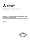
Remarks
Overall cable distance
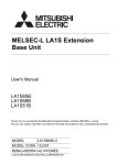
(1) MELSECNET data link system
The overall cable distance refers to a distance from OUT of the
master station to IN of the master station via a slave station.
Overall cable distance
of MELSECNET
M
L1
L6 MELSECNET R2
R5
L3
R4
Figure 2.1 Overall cable distance of MELSECNET
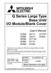
(2) MELSECNET/B data link system
The overall cable distance refers to a distance between stations at
both ends.
The overall cable distance of the MELSECNET/B data link system
is determined depending on communication speed.
The communiation speed is set by the communication speed
setting switch of each link module.
Table 2.4 Communication speed and overall cable distance
Communication speed
125kbps
250kbps
500kbps
1Mbps
Overall cable distance
1200m
600m
400m
200m
Overall cable distance of MELSECNET/B
M
L1
L2
L3
Figure 2.2 Overall cable distance of MELSECNET/B
8
3. HANDLING
3.1 Handling Precautions
(1) Do not drop or give strong impact on the module, since its case is
made of resin.
(2) Do not remove a printed-circuit board of the module from a case.
Doing so may cause failure.
(3) Be careful to prevent foreign matter such as wire chips from
entering the module top at the time of wiring.
(4) Tighten a module mounting screw or a terminal screw within the
following range.
Table 3.1 Screw tightening torque
Screw
Terminal screw for cable terminal block (M3.5 screw)
Mounting screw for cable terminal block (M3.5 screw)
Module mounting screw (M4 screw)
(4)
Tightening torque range
59 to 88N•cm
59 to 88N•cm
78 to 118N•cm
Serrer chaque vis de fixation du module ou vis de borne dans les
limites prescrites ci-après.
Vis
Plage de couple de serrage
Vis de borne sur bornier de câble (Vis M3,5)
59 à 88 N•cm
Vis de fixation de bornier de câble (Vis M3,5)
59 à 88 N•cm
Vis de fixation du module (Vis M4)
78 à 118 N•cm
9
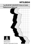
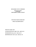
4. PART NAMES AND SETTINGS
This chapter describes the part names and settings of the local module.
1)
1)
1)
2)
2)
3)
3)
3)
4)
2)
7)
5)
6)
Figure 4.1 Outside drawing of local module
Table 4.1 Part names and settings
No.
Name
LED
Name
RUN
SD
RD
F.LOOP
Status
ON
CPU
1)
125k
250k
500k
1M
CRC
OVER
AB.IF
Description
Description
Data link normal
Data sending
Data receiving
Forward loop side receives data (OFF:
Reverse loop side receives data)
Communication with CPU module in
execution
Setting status of communication speed
(A1SJ71AT23BQ)
ON
Code check error for receive data
The processing of receive data has been
delayed.
ON (OFF
if normal) • "1" has been received consecutively
more than stipulated times.
• Receive data length is shorter than
stipulated length.
10
Table 4.1 Part names and settings (Continued)
No.
1)
Name
LED (Continued)
TIME
DATA
UNDER ON (OFF
if normal)
UND.
F.LOOP
R.LOOP
Description
Data link monitoring time is over.
The data of error code has been received.
Internal processing of send data is not
executed constantly.
Receive error at forward loop side
Receive error at reverse loop side
Station No. setting
switch
2)
(A1SJ71AP23Q/
A1SJ71AR23Q)
Tens
place
Ones
place
(A1SJ71AT23BQ)
Tens
place
Ones
place
Mode setting switch
(A1SJ71AP23Q/
A1SJ71AR23Q)
(A1SJ71AT23BQ)
Sets station No. of the local module. (Factory default setting: 1)
• A1SJ71AP23Q/A1SJ71AR23Q
1 to 64: Station No.
(If other than above is set, the local module goes into offline
status (X0=ON).)
• A1SJ71AT23BQ
1 to 31: Station No.
(If other than above is set, the local module goes into offline
status (X0=ON).)
Sets operation mode. (Factory default setting: 0)
No.
Item
Description
Data link (with automatic return
0
Online
function)
Data link (without automatic
1
Online
return function)
2
Offline
Disconnects host station.
3
-
4
-
3)
5
6
7
8 to F
Unusable (If set, the local
module goes into offline status
(X0=ON).)
Station-to-station
test (Executing
station)
Station-to-station
test (Other station)
Self-loopback test
-
11
Checks a line between two
adjacent stations.
Checks the hardware including
transmission circuit in a single
local module.
Unusable (If set, the local
module goes into offline status
(X0=ON).)
Table 4.1 Part names and settings (Continued)
No.
Name
4)
Communication
speed setting switch
(A1SJ71AT23BQ)
5)
Connector
(A1SJ71AP23Q)
Connecteur
(A1SJ71AP23Q)
Description
Sets communication speed.
No.
Communication speed
0
125kbps
1
250kbps
2
500kbps
3
1Mbps
Unusable (If set, the local module goes into offline
4 to F
status (X0=ON).)
Connects an optical fiber cable.
Raccordement par câble à fibres optiques
IN
Reverse loop send
IN
Foward loop receive
OUT Foward loop send
OUT Reverse loop receive
Connects a coaxial cable.
Raccordement par câble coaxial
6)
Connector
(A1SJ71AR23Q)
Connecteur
(A1SJ71AR23Q)
Reverse loop receive OUT R-RD
IN R-SD Reverse loop send
Foward loop send
IN F-RD Foward loop receive
OUT F-SD
Connects a shielded twisted pair cable.
Raccordement par câble à paire torsadée avec blindage
7)
Terminal block
(A1SJ71AT23BQ)
Plaque à bornes
(A1SJ71AT23BQ)
English
French
Foward loop receive
Réception boucle avant
Foward loop send
Émission boucle avant
Reverse loop receive
Réception boucle retour
Reverse loop send
Émission boucle retour
12
5. WIRING
5.1 Optical Fiber Cable
This section describes how to connect an optical fiber cable with the
local module.
(1) Precautions for wiring
(a) Securing of wiring space
When an optical fiber cable is connected with the local module,
a cable bend radius is restricted.
For details, check the specifications of the cable to be used.
(b) Laying an optical fiber cable
When laying an optical fiber cable, do not directly touch an
optical fiber core of a plug or jack, and prevent dirt or dust from
attaching it.
If oil from hand, dirt, or dust is attached, transmission loss may
increase, resulting in failure at data link.
In addition, do not remove the cover from a connector of the
module before installing an optical fiber cable.
(c) Installing/removing an optical fiber cable
Be sure to shut off all phases of the external power supply
used by the system.
(2) Connection of cable
An optical fiber cable connects OUT and IN as shown below. (OUT
of the last station is connected to IN of the master station.)
Slave station Slave station
Master station
No.2
No.1
Station
No. 02
OUT
IN
Front
Station
No. 01
OUT
IN
Front
Station
No. 00
OUT
Figure 5.1 Connection method
13
IN
Front
5.2 Coaxial Cable
This section describes how to connect a coaxial cable with the local
module.
(1) Precautions for wiring
(a) Securing of wiring space
When a coaxial cable is connected with the local module, a
cable bend radius is restricted.
Local
module
A
r
Figure 5.2 Allowable bend radius of coaxial cable
Table 5.1 Allowable bend radius of coaxial cable
Applicable cable
3C-2V
5C-2V
Connector part A
Coaxial cable
Allowable bend radius r
23mm
30mm
30mm
(b) Laying a coaxial cable
When laying a coaxial cable, keep a distance of 100mm (3.94
inch) or more from other power cables or control cables.
In addition, connecting FGs of the power supply module of the
base unit where the local module is mounted strengthens
measures against noise.
(c) Installing/removing a coaxial cable
Be sure to shut off all phases of the external power supply
used by the system.
(2) Connection of cable
A coaxial cable connects OUT(F-SD, R-RD) and IN (F-RD, R-SD)
as shown below. (OUT(F-SD, R-RD) of the last station is connected
to IN (F-RD, R-SD) of the master station.)
Slave station No.2
Slave station No.1
Master station
Station No. 02
Station No. 01
Station No. 00
Front
Figure 5.3 Connection method
14
IN
F-SD
F-RD
R-SD
OUT
R-RD
Front
IN
F-SD
F-RD
R-SD
OUT
R-RD
IN
F-SD
F-RD
R-SD
R-RD
OUT
Front
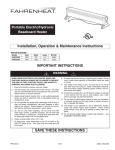
(3) Connection of cable for coaxial cable
The following shows how to connect a BNC connector (connector
plug for coaxial cable) and a cable.
(a) Components of BNC connector and coaxial cable
Components of coaxial cable
Components of BNC connector
Nut
Washer
Gasket
External conductor
External sheath Insulator
Plug shell
Clamp
Contact
Internal conductor
Figure 5.4 Components of BNC connector and coaxial cable
(b) How to connect BNC connector and coaxial cable
1) Remove external sheath of a coaxial cable as shown
below.
Be careful not to damage an external conductor.r.
A
Applicable cable
A
3C-2V
15mm (0.59 in.)
5C-2V
10mm (0.4 in.)
Measures for removing external sheath
2) Put a nut, washer, gasket, and clamp through the coaxial
cable and unravel the external conductor.
Clamp
Nut
Washer
Gasket
3) Cut the external conductor, insulator, and internal
conductor in the following dimensions.
As for the external conductor, cut it in the same dimensions
as taper part of the clamp, and smooth it down to the
clamp.
15
Internal conductor
Insulator
B
Clamp and external conductor
C
Applicable cable
3C-2V
5C-2V
B
6mm (0.24 in. )
7mm (0.28 in.)
C
3mm (0.12 in.)
5mm (0.2 in.)
4) Solder a contact to the internal conductor.
Solderd
5) Insert a contact assembly in 4) to a plug shell and screw a
nut into the plug shell.
POINT
(1)
(2)
When soldering an internal conductor and a contact, pay attention to the
following points.
• Do not swell up the soldered part.
• Properly solder a contact and an insulator of the cable without
making space between them or soldering them too tight.
• Perform soldering immediately so as not to modify the insulator.
Before removing/mounting the coaxial cable connector, be sure to touch
a grounded metal object to discharge the static electricity from the
human body.
Not doing so may cause failure of the module.
16
5.3 Shielded Twisted Pair Cable
This section describes how to connect a shielded twisted pair cable with
the local module.
(1) Precautions for wiring
(a) Laying shielded twisted pair cable
When laying a shielded twisted pair cable, pay attention to the
following points so that it will not be affected by noise or surge
induction.
1) Do not install a shielded twisted pair cable together with
the main circuit, high-voltage cable, or load line, and also
do not bring them closer to each other. (Keep a distance of
100mm (3.94 inch) or more between them.)
2) Do not use a part of shielded twisted pair cable (for
example, one pair among three pairs) as a cable for power
supply.
(b) Connection of terminating resistor
For the stations at both ends of the MELSECNET/B data link
system, connect SDA/RDA and SDB/RDB with an attahced
terminating resistor (110 , 1/2W).
(c) Installing/removing shielded twisted pair cable
Be sure to shut off all phases of the external power supply
used by the system.
(2) Connection of cable
A shielded twisted pair cable is connected as shown below.
In addition, use a terminating resistor for stations at both ends.
Terminating
resistor
(110 1/2W)
SDA/RDA
SDA/RDA
SDA/RDA
SDA/RDA
SDB/RDB
SDB/RDB
SDB/RDB
SDB/RDB
SG(L)
SG(L)
SG(L)
SG(L)
FG
FG
FG
FG
Shielded twisted pair cable
Figure 5.5 Connection method
17
Terminating
resistor
(110 1/2W)
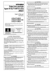
6. EXTERNAL DIMENSIONS
4.5
Printed-circuit board
6.5
93.6
*1
130
6.1 A1SJ71AP23Q
34.5
Figure 6.1 A1SJ71AP23Q
*1
For details, contact your local Mitsubishi Electric System Service or
representative.
18
Unit: mm
130
6.2 A1SJ71AR23Q
30
7
Printed-circuit board
6.5
93.6
34.5
Figure 6.2 A1SJ71AR23Q
19
Unit: mm
130
6.3 A1SJ71AT23BQ
Printed-circuit board
71.6
6.5
14
34.5
93.6
Figure 6.3 A1SJ71AT23BQ
20
Unit: mm
Memo
21
WARRANTY
Mitsubishi will not be held liable for damage caused by factors found not to be the cause of
Mitsubishi; machine damage or lost profits caused by faults in the Mitsubishi products; damage,
secondary damage, accident compensation caused by special factors unpredictable by
Mitsubishi; damages to products other than Mitsubishi products; and to other duties.
Country/Region Sales office/Tel
Country/Region Sales office/Tel
USA
Mitsubishi Electric Automation lnc.
500 Corporate Woods Parkway, Vernon
Hills, IL 60061, USA
Tel : +1-847-478-2100
South Africa
CBI-Electric.
Private Bag 2016, ZA-1600 Isando,
South Africa
Tel : +27-11-977-0770
Brazil
MELCO-TEC Representacao Comercial
e Assessoria Tecnica Ltda.
Av. Paulista, 1439, cj74, Bela Vista,
Sao Paulo CEP: 01311-200-SP Brazil
Tel : +55-11-3146-2200
China
Mitsubishi Electric Automation (China) Ltd.
No.1386 Hongqiao Road, Mitsubishi
Electric Automation Center, Changning
District, Shanghai, China
Tel : +86-21-2322-3030
Germany
Mitsubishi Electric Europe B.V. German
Branch
Gothaer Strasse 8, D-40880 Ratingen,
Germany
Tel : +49-2102-486-0
Taiwan
Setsuyo Enterprise Co., Ltd.
6F., No.105, Wugong 3rd Road, Wugu
District, New Taipei City 24889, Taiwan,
R.O.C.
Tel : +886-2-2299-2499
UK
Mitsubishi Electric Europe B.V. UK Branch
Travellers Lane, Hatfield, Hertfordshire,
AL10 8XB, UK.
Tel : +44-1707-27-6100
Korea
Italy
Mitsubishi Electric Europe B.V. Italian
Branch
Viale Colleoni 7-20864 Agrate Brianza
(Milano), Italy
Tel : +39-039-60531
Mitsubishi Electric Automation
Korea Co., Ltd.
3F, 1480-6, Gayang-Dong, Gangseo-Gu,
Seoul, 157-200, Korea
Tel : +82-2-3660-9530
Singapore
Mitsubishi Electric Europe B.V. Spanish
Branch
Carretera de Rubi 76-80.AC.420, E-08190
Sant Cugat del Valles (Barcelona), Spain
Tel : +34-93-565-3131
Mitsubishi Electric Asia Pte, Ltd. Industrial
Division
307, Alexandra Road, Mitsubishi Electric
Building, Singapore, 159943
Tel : +65-6470-2308
Thailand
Mitsubishi Electric Automation (Thailand)
Co., Ltd.
Bang-Chan Industrial Estate No.111
Soi Serithai 54,
T.Kannayao, A.Kannayao, Bangkok
10230 Thailand
Tel : +66-2906-3238
Indonesia
P. T. Autoteknindo Sumber Makmur
Muara Karang Selatan, Block A / Utara
No.1 Kav. No. 11,
Kawasan Industri Pergudangan,
Jakarta-Utara 14440, P.O, Box 5045,
Indonesia
Tel : +62-21-663-0833
India
Mitsubishi Electric India Pvt. Ltd.
2nd Floor, Tower A & B, Cyber Greens,
DLF Cyber City, DLF Phase-III,
Gurgaon-122002 Haryana, India
Tel : +91-124-463-0300
Australia
Mitsubishi Electric Australia Pty. Ltd.
348 Victoria Road PO BOX11,
Rydalmere, N.S.W 2116, Australia
Tel : +61-2-9684-7777
Spain
France
Mitsubishi Electric Europe B.V. French
Branch
25, Boulevard des Bouvets, F-92741
Nanterre Cedex, France
Tel : +33-1-5568-5568
Czech Republic Mitsubishi Electric Europe B.V.-o.s.Czech
office
Avenir Business Park, Radicka 751/113e,
158 00 Praha5, Czech Republic
Tel : +420-251-551-470
Poland
Mitsubishi Electric Europe B.V. Polish
Branch
ul. Krakowska 50, 32-083 Balice, Poland
Tel : +48-12-630-47-00
Russia
Mitsubishi Electric Europe B.V. Russian
Branch St.Petersburg office
Piskarevsky pr. 2, bld 2, lit "Sch", BC
"Benua", office 720; 195027,
St. Petersburg, Russia
Tel : +7-812-633-3497
HEAD OFFICE : TOKYO BUILDING, 2-7-3 MARUNOUCHI, CHIYODA-KU, TOKYO 100-8310, JAPAN
NAGOYA WORKS : 1-14, YADA-MINAMI 5-CHOME, HIGASHI-KU, NAGOYA, JAPAN
When exported from Japan, this manual does not require application to the Ministry
of Economy, Trade and Industry for service transaction permission.
Specifications subject to change without notice.