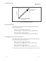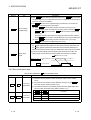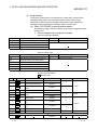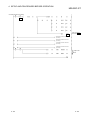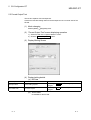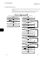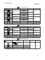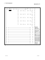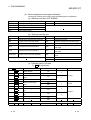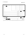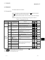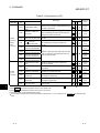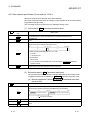
1
MITSUBISHI ELECTRIC MELSEC ST Series Programmable Logic Controllers User's Manual Analog-Digital Converter Modules ST1AD2-V ST1AD2-I Art. no.: 157182 01 01 2004 SH(NA)-080442ENG Version A MITSUBISHI ELECTRIC INDUSTRIAL AUTOMATION SAFETY PRECAUTIONS (Read these precautions before using.) When using Mitsubishi equipment, thoroughly read this manual and the associated manuals introduced in this manual. Also pay careful attention to safety and handle the module properly. The precautions given in this manual are concerned with this product. Refer to the user's manual of the network system to use for a description of the network system safety precautions. These SAFETY PRECAUTIONS classify the safety precautions into two categories: "DANGER" and "CAUTION". DANGER Indicates that incorrect handling may cause hazardous conditions, resulting in death or severe injury. ! CAUTION Indicates that incorrect handling may cause hazardous conditions, resulting in medium or slight personal injury or physical damage. ! Depending on circumstances, procedures indicated by ! CAUTION may also be linked to serious results. In any case, it is important to follow the directions for usage. Store this manual in a safe place so that you can take it out and read it whenever necessary. Always forward it to the end user. [DESIGN PRECAUTIONS] ! DANGER If a communication error occurs in the network, the error station (MELSEC-ST system) shows the following behavior.All outputs turn OFF. (In the MELSEC-ST system, the output status at the time of error can be set to clear/hold/preset by using user parameters of each slice module. As “clear” is set by default, the outputs turn OFF when an error occurs. In the case where the system operates safely with the output set to “hold” or “preset”, change the parameter settings.)Create in the program an interlock circuit that will ensure the system operates safely based on the communication status information.Failure to do so may cause an accident due to mis-output or malfunction. Create an external fail safe circuit that will ensure the MELSEC-ST system operates safely, even when the external power supply or the system fails. Accident may occur due to output error or malfunctioning. (1) The status of output changes depending on the setting of various functions that control the output. Take sufficient caution when setting for those functions. (2) Normal output may not be obtained due to malfunctions of output elements or the internal circuits.Configure a circuit to monitor signals which may lead to a serious accident. A-1 A-1 [DESIGN PRECAUTIONS] ! CAUTION Make sure to initialize the network system after changing parameters of the MELSEC-ST system or the network system. If unchanged data remain in the network system, this may cause malfunctions. Do not install the control wires or communication cables together with the main circuit or power wires. Keep a distance of 100 mm (3.94 inch) or more between them. Not doing so could result in malfunctions due to noise. [INSTALLATION PRECAUTIONS] ! CAUTION Use the MELSEC-ST system in the general environment specified in the MELSEC-ST system users manual. Using this MELSEC-ST system in an environment outside the range of the general specifications could result in electric shock, fire, erroneous operation, and damage to or deterioration of the product. Mount the head module and base module on the DIN rail securely (one rail for one module) referring to the MELSEC-ST system users manual and then fix them with stoppers. Incorrect mounting may result in a fall of the module, short circuits or malfunctions. Secure the module with several stoppers when using it in an environment of frequent vibration. Tighten the screws of the stoppers within the specified torque range. Undertightening can cause a drop, short circuit or malfunction. Overtightening can cause a drop, short circuit or malfunction due to damage to the screw or module. Make sure to externally shut off all phases of the power supply for the whole system before mounting or removing a module. Failure to do so may damage the module. (1) Online replacement of the power distribution module and/or the base module is not available. When replacing either of the modules, shut off all phases of the external power supply. Failure to do so may result in damage to all devices of the MELSEC-ST system. (2) The I/O modules and the intelligent function modules can be replaced online. Since online replacement procedures differ depending on the module type, be sure to make replacement as instructed. For details, refer to the chapter of online module change in this manual. Do not directly touch the module's conductive parts or electronic components. Doing so may cause malfunctions or failure of the module. Make sure to securely connect each cable connector. Failure to do so may cause malfunctions due to poor contact. A-2 A-2 [INSTALLATION PRECAUTIONS] ! CAUTION DIN rail must be conductive; make sure to ground it prior to use. Failure to do so may cause electric shocks or malfunctions. Undertightening can cause a drop, short circuit or malfunction. Overtightening can cause a drop, short circuit or malfunction due to damage to the screw or module. [WIRING PRECAUTIONS] ! DANGER Completely turn off the external power supply when installing or placing wiring. Not completely turning off all power could result in electric shock or damage to the product. ! CAUTION Make sure to ground the control panel where the MELSEC-ST system is installed in the manner specified for the MELSEC-ST system. Failure to do so may cause electric shocks or malfunctions. Check the rated voltage and the terminal layout and wire the system correctly. Connecting an inappropriate power supply or incorrect wiring could result in fire or damage. Tighten the terminal screws within the specified torque. If the terminal screws are loose, it could result in short circuits, fire, or erroneous operation. Overtightening may cause damages to the screws and/or the module, resulting in short circuits or malfunction. Prevent foreign matter such as chips or wiring debris from entering the module. Failure to do so may cause fires, damage, or erroneous operation. When connecting the communication and power supply cables to the module, always run them in conduits or clamp them. Not doing so can damage the module and cables by pulling a dangling cable accidentally or can cause a malfunction due to a cable connection fault. When disconnecting the communication and power supply cables from the module, do not hold and pull the cable part. Disconnect the cables after loosening the screws in the portions connected to the module. Pulling the cables connected to the module can damage the module and cables or can cause a malfunction due to a cable connection fault. A-3 A-3 [STARTUP AND MAINTENANCE PRECAUTIONS] ! DANGER Do not touch the terminals while power is on. Doing so could cause shock or erroneous operation. Make sure to shut off all phases of the external power supply for the system before cleaning the module or tightening screws. Not doing so can cause the module to fail or malfunction. [STARTUP AND MAINTENANCE PRECAUTIONS] ! CAUTION Do not disassemble or modify the modules. Doing so could cause failure, erroneous operation, injury, or fire. Do not drop or give a strong impact to the module since its case is made of resin. Doing so can damage the module. Make sure to shut off all phases of the external power supply for the system before mounting/removing the module onto/from the control panel. Not doing so can cause the module to fail or malfunction. Before handling the module, make sure to touch a grounded metal object to discharge the static electricity from the human body. Failure to do say cause a failure or malfunctions of the module. When using any radio communication device such as a cellular phone, keep a distance of at least 25cm (9.85 inch) away from the MELSEC-ST system. Not doing so can cause a malfunction. [DISPOSAL PRECAUTIONS] ! CAUTION When disposing of this product, treat it as industrial waste. A-4 A-4 REVISIONS The manual number is given on the bottom left of the back cover. Print Date Jan., 2004 Manual Number SH(NA)-080442ENG-A First edition Revision Japanese Manual Version SH-080441-A This manual confers no industrial property rights or any rights of any other kind, nor does it confer any patent licenses. Mitsubishi Electric Corporation cannot be held responsible for any problems involving industrial property rights which may occur as a result of using the contents noted in this manual. 2004 MITSUBISHI ELECTRIC CORPORATION A-5 A-5 INTRODUCTION Thank you for choosing the ST1AD2-V/ST1AD2-I type MELSEC-ST analog-digital conversion module. Before using the module, please read this manual carefully to fully understand the functions and performance of the ST1AD2-V/ST1AD2-I type MELSEC-ST analog-digital conversion module and use it correctly. CONTENTS SAFETY PRECAUTIONS..............................................................................................................................A- 1 REVISIONS ....................................................................................................................................................A- 5 INTRODUCTION............................................................................................................................................A- 6 About Manuals ...............................................................................................................................................A- 9 Compliance with the EMC Directive and the Low Voltage Directive ............................................................A- 9 How to Read Manual......................................................................................................................................A-10 About the Generic Terms and Abbreviations ................................................................................................A-12 Term definition................................................................................................................................................A-13 1 OVERVIEW 1- 1 to 1- 2 1.1 Features ................................................................................................................................................... 1- 1 2 SYSTEM CONFIGURATION 2- 1 to 2- 2 2.1 Overall Configuration ............................................................................................................................... 22.2 Applicable System.................................................................................................................................... 22.2.1 Applicable head module.................................................................................................................... 22.2.2 Applicable base module.................................................................................................................... 22.2.3 Applicable coding element................................................................................................................ 22.2.4 Applicable software package ............................................................................................................ 22.3 Precautions for System Configuration..................................................................................................... 23 SPECIFICATIONS 1 2 2 2 2 2 2 3- 1 to 3-21 3.1 Performance Specifications ..................................................................................................................... 3- 1 3.2 I/O Conversion Characteristics................................................................................................................ 3- 2 3.2.1 Input characteristics of ST1AD2-V ................................................................................................... 3- 2 3.2.2 Input characteristics of ST1AD2-I..................................................................................................... 3- 4 3.2.3 Relation between the offset/gain setting and digital output value ................................................... 3- 6 3.2.4 Accuracy............................................................................................................................................ 3- 6 3.2.5 Conversion speed ............................................................................................................................. 3- 7 3.2.6 Intelligent function module processing time ..................................................................................... 3- 7 3.3 Function.................................................................................................................................................... 3- 8 3.3.1 Function list........................................................................................................................................ 3- 8 3.3.2 A/D conversion method..................................................................................................................... 3-10 3.3.3 Alarm output function ........................................................................................................................ 3-12 3.3.4 Disconnection detection function...................................................................................................... 3-13 3.4 I/O Data .................................................................................................................................................... 3-14 3.4.1 Bit input area ..................................................................................................................................... 3-15 3.4.2 Error information area ....................................................................................................................... 3-16 A-6 A-6 3.4.3 Module status area............................................................................................................................ 3-17 3.4.4 Word input area................................................................................................................................. 3-17 3.4.5 Bit output area ................................................................................................................................... 3-18 3.4.6 Error clear area.................................................................................................................................. 3-19 3.4.7 Word output area............................................................................................................................... 3-19 3.5 Memory and Parameters ......................................................................................................................... 3-20 3.5.1 Memory.............................................................................................................................................. 3-20 3.5.2 Parameters ........................................................................................................................................ 3-21 4 SETUP AND PROCEDURES BEFORE OPERATION 4- 1 to 4-24 4.1 Handling Precautions............................................................................................................................... 44.2 Setup and Procedure before Operation .................................................................................................. 44.3 Part Names .............................................................................................................................................. 44.3.1 Status confirmation by LED .............................................................................................................. 44.4 Wiring........................................................................................................................................................ 44.4.1 Wiring precautions............................................................................................................................. 44.4.2 External wiring ................................................................................................................................... 44.5 Offset/Gain Settings ................................................................................................................................. 45 GX Configurator-ST 5- 1 to 5-10 5.1 GX Configurator-ST Functions ................................................................................................................ 55.2 Project Creation........................................................................................................................................ 55.3 Parameter Setting .................................................................................................................................... 55.4 Input/Output Monitor ................................................................................................................................ 55.5 Forced Output Test .................................................................................................................................. 55.6 Offset/Gain Setting................................................................................................................................... 56 PROGRAMMING 1 2 3 4 5 5 6 8 1 2 3 6 7 9 6- 1 to 6-29 6.1 Programming Procedure.......................................................................................................................... 6- 2 6.2 When QJ71PB92D is Used as Master Station ....................................................................................... 6- 4 6.2.1 Program example available when auto refresh is used in QJ71PB92D ......................................... 6-12 6.3 When AJ71PB92D/A1SJ71PB92D is Used as Master Station .............................................................. 6-19 7 ONLINE MODULE CHANGE 7- 1 to 7-11 7.1 Precautions for Online Module Change .................................................................................................. 77.2 Preparations for Online Module Change................................................................................................. 77.3 Disconnecting/connecting the External Device for Online Module Change .......................................... 77.4 Online Module Change Procedure .......................................................................................................... 77.4.1 When parameter setting or offset/gain setting is performed using GX Configurator-ST during online module change.......................................................................... 78 COMMAND 1 3 3 4 4 8- 1 to 8-45 8.1 Command List .......................................................................................................................................... 8- 1 A-7 A-7 8.2 Common Command................................................................................................................................. 8- 3 8.2.1 Operating status read request (Command No.: 0100H)................................................................... 8- 3 8.2.2 Error code read request (Command No.: 0101H) ............................................................................ 8- 5 8.3 ST1AD Parameter Setting Read Command ........................................................................................... 8- 7 8.3.1 A/D conversion enable/disable setting read (Command No.: 1100H) ............................................. 8- 7 8.3.2 A/D conversion completion channel read (Command No.: 1101H) ................................................. 8- 9 8.3.3 Operation condition set value read (Command No.: 1102H) ........................................................... 8-11 8.3.4 Notch filter set value read (Command No.: 1103H).......................................................................... 8-13 8.3.5 CH time/count averaging setting read (Command No.: 1104H).................................................... 8-14 8.3.6 CH upper upper/upper lower limit set value read (Command No.: 1108H, 110AH)...................... 8-16 8.3.7 CH lower upper/lower lower limit set value read (Command No.: 1109H, 110BH)....................... 8-18 8.3.8 Input range set value read (Command No.: 1118H)......................................................................... 8-20 8.4 ST1AD Parameter Setting Write Command ........................................................................................... 8-23 8.4.1 A/D conversion enable/disable setting write (Command No.: 2100H)............................................. 8-23 8.4.2 Operation condition set value write (Command No.: 2102H)........................................................... 8-25 8.4.3 Notch filter set value write (Command No.: 2103H) ......................................................................... 8-27 8.4.4 CH time/count averaging setting write (Command No.: 2104H) ................................................... 8-28 8.4.5 CH upper upper/upper lower limit set value write (Command No.: 2108H, 210AH) ..................... 8-30 8.4.6 CH lower upper/ lower lower limit set value write (Command No.: 2109H, 210BH)...................... 8-32 8.5 ST1AD Control Command....................................................................................................................... 8-34 8.5.1 Parameter setting ROM read (Command No.: 3100H) .................................................................... 8-34 8.5.2 Parameter setting ROM write (Command No.: 3101H).................................................................... 8-35 8.5.3 Operation mode setting (Command No.: 3102H) ............................................................................. 8-37 8.5.4 Offset channel specification (Command No.: 3103H) ...................................................................... 8-39 8.5.5 Gain channel specification (Command No.: 3104H) ........................................................................ 8-41 8.5.6 User range write (Command No.: 3105H) ........................................................................................ 8-43 8.6 Values Stored into Command Execution Result..................................................................................... 8-44 9 TROUBLESHOOTING 9- 1 to 9- 5 9.1 Error Code List ......................................................................................................................................... 99.2 Troubleshooting ....................................................................................................................................... 99.2.1 When the RUN LED is flashing or turned off.................................................................................... 99.2.2 When the RUN LED turned on and the ERR. LED turned on ......................................................... 99.2.3 When an digital output values can not be read................................................................................ 9APPENDIX 1 4 4 4 5 App- 1 to App- 3 Appendix 1 Accessories.............................................................................................................................App- 1 Appendix 2 External Dimensions...............................................................................................................App- 2 INDEX A-8 Index- 1 to Index- 2 A-8 About Manuals The following manuals are related to this product. Referring to this list, please request the necessary manuals. Relevant Manuals Manual Name MELSEC-ST System User's Manual Explains the system configuration of the MELSEC-ST system and the performance specifications, functions, handling, wiring and troubleshooting of the power distribution modules, base modules and I/O modules. (Sold separately) MELSEC-ST PRFIBUS-DP Head Module User's Manual Explains the system configuration, specifications, functions, handling, wiring and troubleshooting of the ST1H-PB. (Sold separately) GX Configurator-ST Version 1 Operating Manual Explains how to operate GX Configurator-ST, how to set the intelligent function module parameters, and how to monitor the MELSEC-ST system. (Sold separately) Manual Number (Model Code) SH-080456ENG (13JR72) SH-080436ENG (13JR68) SH-080439ENG (13JU47) Compliance with the EMC Directive and the Low Voltage Directive When incorporating the Mitsubishi MELSEC-ST system that is compliant with the EMC directive and the low voltage directive into other machine or equipment and making it comply with the EMC directive and the low voltage directive, refer to "EMC Directive and Low Voltage Directive" of the MELSEC-ST System User's Manual. The CE logo is printed on the rating plate of the EMC Directive and the Low Voltage Directive. By making this product conform to the EMC directive and low voltage instruction, it is not necessary to make those steps individually. A-9 A-9 How to Read Manual This manual explains each area for input data and output data using the following symbols. (1) Data symbol <Example: Cr Command result area> Cr. 0 (7-0) Range In the case of 1-word (16 bit) data, this shows the corresponding range. (0) : Shows 0 bit position (7-0): Shows 0-7 bit range Detail data No. Abbreviated data symbol For details of detail data No. and abbreviated data symbol, refer to (2) and (3) (2) Input data Br Data symbol Br.00 to Br.FF Er Er.00 to Er.FF Error Information Area Mr Mr.0 to Mr.127 Module Status Area Cr Wr 1 Wr.00 to Wr.33 Area Bit Input Area Unit 1 bit/1 signal Detail data No. notation Hexadecimal 1 bit/1 signal Hexadecimal Command Result Area Word Input Area 1 bit/1 signal Decimal 1 word/1 signal Decimal 1 word/1 signal Hexadecimal 1: Following shows the data symbols and the corresponding detail areas within the command result area. Data symbol Cr.0 (15-8) Cr.0 Cr.0 (7-0) A - 10 Area Command Execution Area Start Slice No. of Execution Target Cr.1 Executed Command No. Cr.2 Response Data 1 Cr.3 Response Data 2 A - 10 (3) Output data Bw Data symbol Bw.00 to Bw.FF Ew Ew.00 to Ew.FF Sw Sw.0 to Sw.7 Cw Ww 1 Ww.00 to Ww.33 Area Bit Output Area Unit 1 bit/1 signal Detail data No. notation Hexadecimal Error Clear Area 1 bit/1 signal Hexadecimal System Area 1 word/1 signal Decimal Command Execution Area 1 word/1 signal Decimal Word Output Area 1 word/1 signal Hexadecimal 1: Following shows the data symbols and the corresponding detail areas within the command execution area. Data symbol Cw.0 A - 11 Area Start Slice No. of Execution Target Cw.1 Command No. to be Executed Cw.2 Argument 1 Cw.3 Argument 2 A - 11 About the Generic Terms and Abbreviations This manual uses the following generic terms and abbreviations to describe the ST1AD, unless otherwise specified. Description Generic Term/Abbreviation ST1AD2-V Abbreviation for ST1AD2-V type MELSEC-ST analog-digital conversion module. ST1AD2-I Abbreviation for ST1AD2-I type MELSEC-ST analog-digital conversion module. ST1AD Generic term for ST1AD2-V and ST1AD2-I. Head module ST1H-PB, MELSEC-ST PROFIBUS-DP compatible head module. PROFIBUS-DP PROFIBUS-DP network. Bus refreshing module Module that distributes the external SYS. power supply and external AUX. power supply among the head module and slice modules. Power feeding module Module that distributes external AUX. power supply among slice modules. Power distribution module Bus refreshing module and Power feeding module. Base module Module that transfers data/connects between the head module and slice modules, and between slice modules and external devices. Input module Module that handles input data in bit units. Output module Module that handles output data in bit units. Intelligent function module Module that handles input/output data in word units. I/O module Input module and output module. Slice module Module that can be mounted to the base module: power distribution module, I/O module and intelligent function module. MELSEC-ST system System that consists of head module, slice modules, end plates and end brackets. GX Configurator-ST SWnD5C-STPB-E type products. (n: 1 or later) Configuration software Software used to set slave parameters for head module and slice modules.(e.g., GX Configurator-DP) Industrial shipment setting Generic term for input ranges 1 to 5V, 0 to 5V, 0 to 10V, -10 to 10V, 4 to 20mA and 0 to 20mA. User parameter Generic term for setting items (Input range setting) set by the configuration software of the master station. Command parameter Generic term for setting items (A/D Conversion enable/disable setting, Averaging process specification, Time/count averaging specification, Alarm output setting, Upper upper limit value/Upper lower limit value/Lower upper limit value/Lower lower limit value setting, Disconnection detection setting, Notch filter setting) set by commands. They can also be set by GX Configurator-ST. Parameter Generic term for user parameters and command parameters. A - 12 A - 12 Term definition The following explains the meanings and definitions of the terms used in this manual. Term Definition Master station Class 1 master station that communicates I/O data with slave stations. Slave station Device that communicates I/O data with the master station. Repeater Device that connects PROFIBUS-DP segments. Bus terminator Terminator that is connected to both ends of each PROFIBUS-DP segment GSD file The electronic file that includes description of the slave station parameter. The file is used to set slave parameters by the master station. Data sent from the head module to the master station. The data consists of the following areas. Br Bit Input Area Input data Information Area Er Error Information Area Mr Module Status Area Cr Command Result Area Wr Word Input Area Data that the head module receives from the master station. The data consists of the following areas. Bw Bit Output Area Output data I/O data Br.n bit input Request Area Ew Error Clear Area Sw System Area Cw Command Execution Area Ww Word Output Area Data (input data, output data) transferred between the head module and the master station. Bit input data of each module. Bw.n bit output Bit output data of each module Wr.n word input Word (16-bit) input data of an intelligent function module. In the case of analog input module, the digital output data value is stored. Ww.n word output Word (16-bit) output data of an intelligent function module. In the case of analog output module, the digital setting data value is stored. Information area Bit/Word input data for checking each module status and command execution results. Request area Bit/Word output data for requesting each module to clear errors/to execute commands. The area, that is equivalent to the occupied I/O points, is occupied in Br bit input area/ Bw bit output area. Number of occupied I/O points Slice No. No. assigned to every 2 occupied I/O points of each module. This numbering starts by assigning "0" to the head module and then proceeds in ascending order. (The maximum value No. is 127). The No. is used for specifying the execution target. Command Requesting from the master station in order to read the module status, to set/control the intelligent function module command parameters. A - 13 A - 13 1 OVERVIEW MELSEC-ST 1 OVERVIEW 1 This User's Manual provides the specifications, handling, programming methods, etc. for the ST1AD2-V type MELSEC-ST analog-digital converter module (hereinafter referred to as the ST1AD2-V) and ST1AD2-I type MELSEC-ST analog-digital converter module (hereinafter referred to as the ST1AD2-I). In this manual, the ST1AD2-V and ST1AD2-I are collectively referred to as the ST1AD. This manual describes only the ST1AD. For information on the MELSEC-ST system, refer to the MELSEC-ST System User's Manual. 1.1 Features (1) Available models • ST1AD2-V...... 2-channel voltage input type. • ST1AD2-I........ 2-channel current input type. (2) Up to 26 modules can be mounted For one head module, up to 26 ST1AD modules (52 channels) can be mounted. (3) Input range can be changed for each channel The analog input range*1 can be changed for each channel to change the I/O conversion characteristic. 1 The input range refers to the type of offset/gain settings. The most frequently used range is set as the default, but the user can make offset/gain settings according to the purpose. (4) Alarm output function If a digital output value falls outside a setting range, an alarm is output for each channel. (5) Disconnection detection function Cable disconnection is detected for each channel. (6) Notch filter processing Notch filter processing removes the power supply noise (50Hz/60Hz) of external devices. (Within -60dB) (7) Command function By writing command parameters to the ROM using a command, A/D conversion can be made without setting the command parameters at module start (poweron). 1-1 1-1 1 OVERVIEW MELSEC-ST (8) High-speed conversion processing Conversion speed is as high as 0.1ms/channel when notch filter processing is not performed, or 0.2ms/channel when notch filter processing is performed. (9) High degree of accuracy This module performs A/D conversion at the accuracy of maximum digital output value. 0.8% relative to the (10) Online module change The module can be changed without the system being stopped. (11) Easy settings using the GX Configurator-ST The optional software package (GX Configurator-ST) is available. GX Configurator-ST is not necessarily required for the system. However, we recommend using GX Configurator-ST, as it enables parameter setting and offset/gain setting to be made on the screen, which reduces programs of master station and makes the setting/operating status check easier. 1-2 1-2 1 2 SYSTEM CONFIGURATION MELSEC-ST 2 SYSTEM CONFIGURATION This chapter describes the system configuration for use of the ST1AD. 2.1 Overall Configuration 2 The overall configuration for use of the ST1AD is shown below. <The system which used QJ71PB92D> GSD file Class 1 master station (QJ71PB92D) GX Configurator-DP Bus terminator Slave station Slave station ST1AD Slave station (MELSEC-ST system) GX Configurator-ST ST1PSD ST1H-PB RUN ERR SYS ST1PDD RUN 11 ERR 21 RUN 11 ERR 21 RUN 11 ERR 21 RUN 31 41 51 61 71 81 91 101 111 121 131 141 151 AUX. ERR RUN ERR RUN ERR 161 AUX RELEASE RESET PROFIBUS I/F Sensor etc. Slave station Slave station (MELSEC-ST system) ST1PSD ST1H-PB RUN SYS AUX. ERR ST1PDD RUN 11 ERR 21 RUN 11 ERR RUN ERR RUN ERR RUN ERR 21 AUX RELEASE RESET PROFIBUS I/F Bus terminator Slave station 2-1 2-1 2 SYSTEM CONFIGURATION MELSEC-ST 2.2 Applicable System This section explains the applicable system. 2.2.1 Applicable head module 2 The head module applicable to the ST1AD is indicated below. Product name Model name MELSECT-ST PROFIBUS-DP Head Module ST1H-PB 2.2.2 Applicable base module The base modules applicable to the ST1AD are indicated below. Type Model name Spring Clamp Type ST1B-S4IR2 Screw Clamp Type ST1B-E4IR2 2.2.3 Applicable coding element The coding elements applicable for the ST1AD are indicated below. The coding element is fitted before shipment. It is also available as an option in case it is lost. Description Model name ST1AD2-V coding element ST1A-CKY-13 ST1AD2-I coding element ST1A-CKY-14 2.2.4 Applicable software package The software package applicable to the ST1AD is indicated below. Product name Model name GX Configurator-ST SW1D5C-STPB-E 2.3 Precautions for System Configuration For precautions for ST1AD system configuration, refer to Section 3.4 "Precautions for System Configuration" in MELSEC-ST system user's manual. 2-2 2-2 3 SPECIFICATIONS MELSEC-ST 3 SPECIFICATIONS This chapter provides the specifications of the ST1AD. For the general specifications of the ST1AD, refer to the MELSEC-ST System User's Manual. 3.1 Performance Specifications Table 3.1 indicates the general specifications of the ST1AD. Table 3.1 Performance specifications list 3 Model name Item ST1AD2-V ST1AD2-I Analog input points 2 points (2 channels/module) Voltage DC–10 to 10V (Input resistance value: 1M ) Current — Analog input Analog input range 0 to 10 V 0 to 5 V ST1AD2-V 1 to 5 V (Voltage) -10 to 10V User range setting 0 to 20 mA ST1AD2-I 4 to 20 mA (Current) User range setting I/O characteristics, Maximum resolution Digital output value -4000 to 4000 0 to 4000 Within ± 0.8 % ( 32digit) When notch filter processing is not performed: 0.1 ms/channel When notch filter processing is performed: 0.2 ms/channel Conversion speed Absolute maximum input Voltage 15 V Current — ROM write count — 30 mA ROM write count by user range write or parameter setting: Maximum 10,000 times Number of occupied I/O points Number of Occupied Slices Input data Output data Isolation specifications Applicable base module Applicable coding element External AUX. power supply 4 points for each of input and output 2 Br.n : Number of occupancy 4, Er.n : Number of occupancy 4, Mr.n : Number of occupancy 2, Wr.n : Number of occupancy 2 Bw.n : Number of occupancy 4, Ew.n : Number of occupancy 4, Ww.n : Number of occupancy 2 Specific isolated area Isolation method Dielectric with stand Between analog input terminals and internal bus Between analog input channels Photo coupler insulation No insulation 560V AC rms/3 cycles (elevation 2000m) — Insulation resistance 500V DC 10M more — or Spring clamp type: ST1B-S4IR2, Screw clamp type: ST1B-E4IR2 ST1A-CKY-13(green) ST1A-CKY-14(green) 24V DC (+20/-15%, ripple ratio within 5%) 24V DC current: 0.030A 5V DC internal current consumption Weight Maximum resolution 2.5 mV 1.25 mV 1.0 mV 2.5 mV 1.0 mV 5 A 4 A 4 A 0 to 4000 Accuracy Ambient (Accuracy in respect temperature to maximum digital 0 to 55 °C output value) External dimensions DC0 to 20mA (Input resistance value: 250 ) 16-bit signed binaly (-96 to 4095) 16-bit signed binaly (-4096 to 4095) Digital output Information amount — 0.110 A 77.6 (3.06in.) (H) 12.6 (0.50in.) (w) 55.4 (2.18in.) (D) [mm] 0.04 kg ST1AD needs to be powered on 5 minutes prior to operation for compliance to the specification (accuracy). 3-1 3-1 3 SPECIFICATIONS MELSEC-ST 3.2 I/O Conversion Characteristics An I/O conversion characteristic indicates an inclination of a straight line that connects an offset value and a gain value at the time when an analog value (voltage or current input) from an external device is converted into a digital value. The offset value is an analog input value (voltage or current) at which the digital output value is 0. The gain value is an analog input value (voltage or current) at which the digital output value is 4000. 3.2.1 Input characteristics of ST1AD2-V 3 A graph of the ST1AD2-V input characteristic is shown below. Analog input parcitcal value 4095 4000 1), 2) 2000 3) 4) 0 -96 1 -2000 -4000 -4096 -15 -10 -5 0 5 Analog input voltage (V) 10 No. Analog Input Range Setting Offset Value Gain Value Digital Output Value*2 1) -10 to +10V 0V 10V -4000 to +4000 2) 0 to 10V 0V 10V 3) 0 to 5V 0V 5V 4) 1 to 5V 1V 5V — User range setting *1 *1 0 to 4000 15 Maximum Resolution 2.5mV 1.25mV 1.0mV -4000 to +4000 1.0mV Fig. 3.1 Input characteristics of ST1AD2-V 3-2 3-2 3 SPECIFICATIONS MELSEC-ST POINT (1) Within the analog input and digital output scopes of each input range, the maximum resolution and accuracy are within the performance specification range. Outside those scopes, however, they may not fall within the performance specification range. (Avoid using the dotted line part in Fig. 3.1.) (2) Do not input more than ±15V. The element may be damaged. (3) Set the offset/gain values for the user setting range 1 within a range in which the following conditions are satisfied. (a) (Setting range):-10 to 10V (b) (Gain value) > (Offset value) (c) (Gain value) – (Offset value) 4V If condition (b) is not satisfied, ERR.LED turns on, the value will not be written to the module. When the setting is outside the condition in (c), conversion is made but the resolution is within the maximum resolution range of the performance specifications. (4) When an analog value that exceeds the range for the digital output value 2 is entered, the digital output value will be fixed at the maximum or minimum value. • For 0 to 4000, the digital output value is within the range -96 to 4095. • For -4000 to +4000, the digital output value is within the range -4096 to 4095. 3-3 3-3 3 SPECIFICATIONS MELSEC-ST 3.2.2 Input characteristics of ST1AD2-I A graph of the ST1AD2-I input characteristic is shown below. Analog input parcitcal value 4095 4000 2) 2000 1) 0 -96 4 -2000 -4000 -30 -20 -10 0 10 Analog input current (mA) No. Analog Input Range Setting Offset Value Gain Value 1) 0 to 20mA 0mA 20mA 2) 4 to 20mA 4mA 20mA — User range setting *1 *1 20 Digital Output Value*2 30 Maximum Resolution 5 A 0 to 4000 4 A 4 A Fig. 3.2 Input characteristics of ST1AD2-I 3-4 3-4 3 SPECIFICATIONS MELSEC-ST POINT (1) Within the analog input and digital output scopes of each input range, the maximum resolution and accuracy are within the performance specification range. Outside those scopes, however, they may not fall within the performance specification range. (Avoid using the dotted line part in Fig. 3.1.) (2) Do not input more than ±30mA. The element may be damaged. (3) Set the offset/gain values for the user setting range 1 within a range in which the following conditions are satisfied. (a) (Setting range): 0 to 20mA (b) (Gain value) > (Offset value) (c) (Gain value) – (Offset value) 16mA If condition (b) is not satisfied, ERR.LED turns on, the value will not be written to the module. When the setting is outside the condition in (c), conversion is made but the resolution is within the maximum resolution range of the performance specification. (4) When an analog value that exceeds the range for the digital output value 2 is entered, the digital output value will be fixed at the maximum or minimum value. • For 0 to 4000, the digital output value is within the range -96 to 4095. 3-5 3-5 3 SPECIFICATIONS MELSEC-ST 3.2.3 Relation between the offset/gain setting and digital output value The relation between the offset/gain setting and digital output value is described. (1) Resolution The resolution is obtained by the following formula: Resolution = (Gain value) - (Offset value) 4000 (2) Relation between the maximum resolution and digital output value The maximum resolution of the ST1AD is as indicated in the performance specification. If the following is satisfied from the offset/gain setting, the digital output value does not increases /decreases by one. (Gain value) - (Offset value) 4000 < Maximum resolution 3.2.4 Accuracy Accuracy is relative to the maximum value of the digital output value (4000). If you change the offset/gain setting or input range to change the input characteristic, accuracy does not change and is held within the range indicated in the performance specifications. Accuracy is within ±0.8% (±32 digit). Digital output value 4000 Varies within the range of 0.8% ( 32 digit). 0 -4000 -10V 0V Analog input value 10V Fig. 3.3 Accuracy of ST1AD2-V 3-6 3-6 3 SPECIFICATIONS MELSEC-ST 4000 Digital output value Varies within the range of 0.8% ( 32 digit). 0 0mA 20mA Analog input value Fig. 3.4 Accuracy of ST1AD2-I 3.2.5 Conversion speed The conversion speed of the ST1AD changes depending on whether notch filter processing is performed or not. [When notch filter processing is not performed] (Conversion speed) = 0.1ms number of conversion enabled channels [When notch filter processing is performed] (Conversion speed) = 0.2ms number of conversion enabled channels 3.2.6 Intelligent function module processing time The intelligent function module processing time of the ST1AD changes depending on whether notch filter processing is performed or not. [When notch filter processing is not performed] (Processing time) = 0.1ms number of conversion enabled channels [When notch filter processing is performed] (Processing time) = 0.2ms number of conversion enabled channels For the input transmission delay time, refer to the used head module user's manual. 3-7 3-7 3 SPECIFICATIONS MELSEC-ST 3.3 Function This section explains the functions of ST1AD. 3.3.1 Function list Table 3.2 lists the functions of ST1AD. Table 3.2 ST1AD Function List (1/2) Item A/D conversion enable/disable function A/D conversion method Description Reference section (1) Specifies whether to enable or disable the A/D conversion for each channel. (2) By default, the A/D conversion for all channel is disabled. [Setting method] • A/D conversion enable/disable setting write (Command number: 2100H, see Section 8.4.1) • GX Configurator-ST (see Section 5.3) (1) Sampling process The input analog value is converted to digital value for each channel and the digital value is output. (2) Averaging process The A/D conversion is performed for the specified channel as many times as the setting or for the set time. Then the sum of the values other than the maximum and minimum ones is averaged and output to the digital value. (3) Averaging process setting defaults to Sampling process performed on all channels. (4) Time averaging defaults to 4ms, and number of times averaging defaults to 4 times. [Averaging process specifying method] • Operation condition specification value write (Command number: 2102H, see Section 8.4.2) • GX Configurator-ST (see Section 5.3) [Average time/average number of times setting method] • CH average time/average number of times setting write (Command number: —— Section 3.3.2 2104H, see Section 8.4.4) • GX Configurator-ST (see Section 5.3) (1) The analog input range can be set for each channel to change the I/O conversion characteristics. (2) The input range is selectable from the following. Model Input range -10 to 10V (default) 0 to 10V Input range changing function ST1AD2-V 0 to 5V 1 to 5V —— User range setting 4 to 20mA (default) ST1AD1-I 0 to 20 mA User range setting [Setting method] • Master station configuration software • GX Configurator-ST (see Section 5.3) 3-8 3-8 3 SPECIFICATIONS MELSEC-ST Table 3.2 ST1AD Function List (2/2) Item Alarm output function Disconnection detection function Notch filter processing Command Offset/gain settings Online module change 3-9 Description (1) If a digital output value falls outside a setting range, an alarm is output for each channel. (2) Alarm output setting defaults to No alarm output processing performed on all channels. (3) Set the alarm output in 4 steps: upper upper limit value, upper lower limit value, lower upper limit value and lower lower limit value. The upper upper limit value and upper lower limit value default to 4000. The lower upper limit value and lower lower limit value default to -4000 for the ST1AD2-V 0 for the ST1AD2-I, respectively. [Alarm output setting method] • Operation condition specification value write (Command number: 2102H, see Section 8.4.2) • GX Configurator-ST (see Section 5.3) [Upper upper limit value, upper lower limit value, lower upper limit value and lower lower limit value setting method] • CH upper upper limit value/upper lower limit value setting write (Command number: 2108H, 210AH, see Section 8.4.5) • CH lower upper limit value/lower lower limit value setting write (Command number: 2109H, 210BH, see Section 8.4.6) • GX Configurator- ST (see Section 5.3) (1) For the range of 1 to 5V or 4 to 20mA, cable disconnection is detected for each channel. (2) Defaults to No disconnection detection processing performed on all channels. [Setting method] • Operation condition specification value write (Command number: 2102H, see Section 8.4.2) • GX Configurator- ST (see Section 5.3) (1) Notch filter processing removes the power supply noise (50Hz/60Hz) of external devices. (Within -60dB) Use this function when the module seems to be affected by power supply noise. (2) Notch filter processing is batch-performed for all channels. (3) Notch filter processing can be used independently of sampling processing and averaging processing. (4) Select notch filter processing from among the following types. • No notch filter processing performed on all channels • Notch filter processing performed on all channels (50 3Hz) • Notch filter processing performed on all channels (60 3Hz) (5) Defaults to No notch filter processing performed on all channels. [Setting method] • Notch filter setting write (Command number: 2103H, see Section 8.4.3) • GX Configurator- ST (see Section 5.3) (1) By using commands, command parameters can be set, and the parameter settings can be written from RAM to ROM and read from ROM to RAM. (1) Setting of any offset value/gain value optimizes the I/O conversion characteristic according to the system. [Setting method] • Master station program • GX Configurator-ST (1) A module change is made without the system being stopped. [Execution procedure] • Button operation of head module • GX Configurator-ST Reference section Section 3.3.3 Section 3.3.4 —— Chapter 8 Section 4.5 Section 5.6 Chapter 7 3-9 3 SPECIFICATIONS MELSEC-ST 3.3.2 A/D conversion method There are two conversion methods, sampling process and averaging process. (1) Sampling process The input analog value is converted to a digital value and the digital value is output. Then, the output value is stored in Wr.n , Wr.n+1 CH digital output value. Sampling processing time changes depending on the number of channels used (number of channels set to A/D conversion enable) and whether notch filter processing is performed or not. [When notch filter processing is not performed] (Processing time) = (Number of channels used) 0.1 (ms/1channel) [When notch filter processing is performed] (Processing time) = (Number of channels used) 0.2 (ms/1channel) [Example] When notch filter processing is not performed and channels 1, 2 are used, sampling processing time is 0.2ms. 2 0.1 = 0.2(ms) (2) Averaging process The A/D conversion is performed for the specified channel as many times as the setting or for the set time. Then the sum of the values other than the maximum and minimum ones is averaged and the result is stored in Wr.n , Wr.n+1 CH digital output value. The applicable setting ranges for the time and number of times are given below. When the setting is outside the applicable range, the ERR. LED turns on and the A/D conversion of the corresponding channel stops. • Averaging processing by time: 2 to 5000ms • Averaging processing by the number of times: 4 to 62500 a) When averaging process is set to be performed for the set time The number of processing times within the set time changes depending on the number of channels used (number of channels set to A/D conversion enable) and whether notch filter processing is performed or not. [When notch filter processing is not performed] (Number of processing repetitions) = (set time) (Number of channels used) 0.1 (ms/1channel) [When notch filter processing is performed] (Number of processing repetitions) = 3 - 10 (set time) (Number of channels used) 0.2 (ms/1channel) 3 - 10 3 SPECIFICATIONS MELSEC-ST [Example] When notch filter processing is performed, channels 1, 2 are used, and the set time is 55ms, measurement is made 137 times and an average value is output. 2 b) 55 0.2 = 137.5(times)...Round down the number When the averaging process is set to be performed as many times as the setting The result (average value) of averaging process that is performed as many times as the setting is stored in Wr.n , Wr.n+1 CH digital output value at certain intervals. The storage interval changes depending on the number of channels used (number of channels set to A/D conversion enable) and whether notch filter processing is performed or not. [When notch filter processing is not performed] (Processing time) = (Set number of times) (Number of channels used) 0.1 (ms/1channel) (Unit:ms) [When notch filter processing is performed] (Processing time) = (Set number of times) (Number of channels used) 0.2 (ms/1channel) (Unit:ms) [Example] When notch filter processing is not performed, channels 1, 2 are used, and the set number of times is 500, the average value is output at 100ms intervals. 500 3 - 11 2 0.1 = 100(ms) 3 - 11 3 SPECIFICATIONS MELSEC-ST 3.3.3 Alarm output function (1) If the detected digital value rises to or above the upper upper limit value or falls to or below the lower lower limit value and enters into the alarm output range, Br.n+1 alarm output signal turns on (1) and the error information is stored into Er.n+3 to Er.n CH error information. (2) When the digital value falls below the upper lower limit value or rises above the lower upper limit value and returns to within the setting range after the alarm output, Er.n+3 to Er.n CH error information of the corresponding channel is automatically cleared. Br.n+1 alarm output signal turns off (0) only when digital values return to within the setting range on all channels. (3) Alarm output processing can be set to be performed or not for each channel. Alarm output setting defaults to No alarm output processing performed on all channels. (4) Set the alarm output in 4 steps: upper upper limit value, upper lower limit value, lower upper limit value and lower lower limit value. The setting range is -4096 to 4095 for the ST1AD2-V or -96 to 4095 for the ST1AD2-I, respectively. If a set value is outside the above setting range or the condition of lower lower limit value ( lower upper limit value ( upper lower limit value ( upper upper limit value is not satisfied, that channel will result in an error and the ERR. LED will turn on. The upper upper limit value and upper lower limit value default to 4000. The lower upper limit value and lower lower limit value default to -4000 for the ST1AD2-V, 0 for the ST1AD2-I, respectively. (5) An alarm is output for only the channel for which A/D conversion. Digital output value Upper upper limit value Alarm output range zone Alarm output range outside zone Included Alarm occurrence Alarm occurrence Upper lower limit value Alarm cancel Alarm cancel CH1 digital output value Alarm cancel Lower upper limit value CH2 digital output value Lower lower limit value Alarm occurrence Time Er.n+1 , Er.n CH1 error information Alarm occurrence (01) 00 Er.n+3 , Er.n+2 CH2 error information 00 00 Alarm occurrence (01) Alarm occurrence (01) 00 00 ON(1) Br.n+3 Alarm output signal 3 - 12 OFF(0) 3 - 12 3 SPECIFICATIONS MELSEC-ST 3.3.4 Disconnection detection function (1) The disconnection detection function is usable in the range of 1 to 5V or 4 to 20mA only. (2) If the analog input value falls to or below 0.5V in the 1 to 5V range, or to or below 2mA in the 4 to 20mA range, the ERR. LED turns on and the error information is stored into Er.n+3 to Er.n CH error information. (3) Er.n+3 to Er.n CH error information is cleared by Ew.n error clear request. (Refer to Section 3.4.6.) (4) Disconnection detection processing can be set to be performed or not for each channel. Disconnection detection setting defaults to No disconnection detection processing performed on all channels.[Setting method] (5) Disconnection is detected on only the channel for which A/D conversion is enabled. (6) The accuracy of disconnection detection is the same as that of this module. (Refer to Section 3.2.4.) (7) If a disconnection is detected during digital output, the digital output value prior to the disconnection detection is held. 5V/20mA Analog input value (V/mA) 0.5V/2mA Disconnection assumed range 0 Er.n+3 to 3 - 13 Er.n CH error information 00 Disconnection detection (11) 3 - 13 3 SPECIFICATIONS MELSEC-ST 3.4 I/O Data The ST1AD has the areas for data transfer with the head module as indicated in Table 3.3. This section explains the composition of each area. Table 3.3 I/O Data List Transfer direction Item Br Bit Input Area ST1AD Head module ST1AD (Output Data) 3 - 14 Default value Reference section 4 0 Section 3.4.1 Er Error Information Area 4 0 Section 3.4.2 Mr Module Status Area 2 0 Section 3.4.3 Wr Word Input Area 2 0 Section 3.4.4 Bw Bit Output Area 4 0 Section 3.4.5 4 0 Section 3.4.6 2 0 Section 3.4.7 Head module (Input Data) Number of Occupancy Information Area Request Area Ew Error Clear Area Ww Word Output Area 3 - 14 3 SPECIFICATIONS MELSEC-ST 3.4.1 Bit input area This section explains the Br bit input area. Bit input Item Description (1) Turns on (1) when A/D conversion is ready after the MELSEC-ST system (ST1AD) is powered on or the head module is reset. (2) When the Br.n Module ready signal is off (0), A/D conversion processing is not performed. Br.n Module ready Br.n Module ready turns off (0) in the following situations: • In offset/gain setting mode • When the ST1AD has a watchdog timer error • In module change enabled status during online module change (refer to Chapter 7) (1) After Bw.n+1 convert setting request has turned on (1), this turns on (1) when user parameter and command parameter setting check is completed. (Turns on (1) if a setting error is detected.) [When parameter setting check result is normal] Performed by the ST1AD Performed by the master station program Br.n Br.n+1 Convert setting completed flag Wr.n Module ready Bw.n+1 Convert setting request Br.n+1 Convert setting completed flag Br.n+2 A/D conversion completed flag , Wr.n+1 CH Digital setting value 0 Digital value 0 [When parameter setting check result is abnormal] Performed by the ST1AD Performed by the master station program Br.n Wr.n Bw.n+1 Convert setting request Br.n+1 Convert setting completed flag Br.n+2 A/D conversion completed flag , Wr.n+1 CH Digital value Er.n+3 to 3 - 15 Module ready Er.n CH error information OFF(0) 0 00 Error detection 3 - 15 3 SPECIFICATIONS Bit input MELSEC-ST Item Description (1) After Bw.n+1 convert setting request has turned on (1), Br.n+2 A/D conversion completed flag turns on (1) when A/D conversion is completed on all channels for which A/D conversion is enabled. (2) The Br.n+2 A/D conversion completed flag is processed only once when the Bw.n+1 convert setting request is changed. Br.n+2 A/D conversion (a) When Bw.n+1 convert setting request is turned from off (0) to on (1) When the digital value converted from an analog value is stored into Wr.n , completed flag Wr.n+1 CH digital output value, Br.n+2 A/D conversion completed flag turns on (1). Specifying notch filter processing or averaging process will cause a delay in turning Br.n+2 A/D conversion completed flag on (1) by the processing time. (b) When Bw.n+1 convert setting request is turned from on (1) to off (0) Br.n+2 A/D conversion completed flag turns off (0). (1) Turns on (1) when the digital output value falls outside the setting range for the CH upper upper limit value/upper lower limit value (command parameter) and CH lower upper limit value/lower lower limit value (command parameter) on either channel where the alarm output is validated and A/D conversion is enabled. (2) Turns off (0) automatically when the digital output value returns to within the Br.n+3 Alarm output setting range on all channels for which enabled A/D conversion is enabled. signal Performed by the ST1AD Er.n+3 to Er.n CH error information 00 Alarm occurrence (01) 00 Br.n+3 Error clear request 3.4.2 Error information area This section explains the Er error information area. Error information Item Description (1) Stores the error information or alarm information when an error or alarm occurs. (2) The stored error information can be cleared by turning on (1) the Ew.n Er.n+1 Er.n CH1 error information error clear request. (Refer to Section 3.4.6) (3) The alarm information is automatically cleared when the digital output value returns to within the setting range. (Refer to Section 3.4.1.) Er.n+3 3 - 16 Er.n+2 CH2 error information Er.n+1 Er.n Er.n+3 Er.n+2 0 0 Normal 0 1 Alarm has occurred 1 1 System error has occurred Information 3 - 16 3 SPECIFICATIONS MELSEC-ST 3.4.3 Module status area This section explains the Mr module status area. Module status Item Description (1) The operating status of the ST1AD is stored. Mr.n+1 Mr.n Mr.n+1 Mr.n 0 0 Online module change in progress or internal bus error occurred 1 1 Normal Module status Information 3.4.4 Word input area This section explains the Wr word input area. Word input Wr.n Wr.n+1 3 - 17 Item CH1 digital output value CH2 digital output Description (1) The digital value converted from an analog value is stored into Wr.n , Wr.n+1 CH digital output value for each channel. (2) The digital value is stored in 16-bit, signed binary. value 3 - 17 3 SPECIFICATIONS MELSEC-ST 3.4.5 Bit output area This section explains the Bw bit output area. Bit output Item Bw.n System area Description Use prohibited (fixed to 0) (1) Turn this item from off (0) to on (1) to validate the settings of the user parameters and command parameters. (a) When writing the command parameters, make sure to turn the Bw.n+1 convert setting request off (0) to stop the conversion. When it is on (1), the command parameters cannot be written. (b) Regardless of whether the Bw.n+1 convert setting request is on (1) or off Bw.n+1 Convert setting request (0), the user parameters are written but not validated. (Turn the Bw.n+1 convert setting request from off (0) to on (1).) (2) Turn this on (1) to start A/D conversion for the channel for which conversion set to be enabled in the A/D conversion enable/disable setting (command parameter). (3) For the on (1)/off (0) timing, refer to the Br.n+1 column in Section 3.4.1. OFF (0): A/D Conversion stop (Default) ON (1): A/D Conversion start Bw.n+2 Bw.n+3 3 - 18 System area Use prohibited (fixed to 0) 3 - 18 3 SPECIFICATIONS MELSEC-ST 3.4.6 Error clear area This section explains the Ew error clear area. Error clear area Item Description (1) Turn this request on (1) to clear the Er.n+3 to Er.n CH (2) After confirming that the Er.n+3 to Er.n CH error information. error information has been cleared, turn off (0) the Ew.n error clear request. OFF (0): No error clear requested (Default) ON (1): Error clear requested Ew.n Error clear request Performed by the ST1AD Performed by the master station program Er.n+3 to Ew.n error clear request Er.n CH error information 00 Error detection 00 Ew.n+1 Ew.n+2 System area Use prohibited (fixed to 0) Ew.n+3 3.4.7 Word output area The ST1AD does not use the Ww word output area. The ST1AD can operate the Ww word output area is secured for it. To make effective use of the Ww word output area, select "ST1AD2-V (without Ww)" or "ST1AD2-I (without Ww)" using the configuration software of the master station or GX Configurator-ST. The number of occupancy of the Ww word output area in the ST1AD is 0. 3 - 19 3 - 19 3 SPECIFICATIONS MELSEC-ST 3.5 Memory and Parameters This section explains the memory and parameters of the ST1AD. 3.5.1 Memory RAM and ROM are available as the parameter storage memory of the ST1AD. (1) RAM (a) The ST1AD operates based on the parameter settings stored in the RAM. (b) The parameter settings stored in the RAM become valid when the Bw.n+1 convert setting request turns from OFF to ON. (2) ROM 3 - 20 (a) The ROM stores the parameters. The stored parameters are not erased at power-off. (b) The parameters stored in the ROM are transferred to the RAM when: • The MELSEC-ST system (ST1AD) is powered off, then on. • The head module is reset. • Parameter setting ROM read (command number: 3100H) is executed. 3 - 20 3 SPECIFICATIONS MELSEC-ST 3.5.2 Parameters The ST1AD has user parameters and command parameters. (1) User parameters (a) Setting item • Input range setting (b) Setting method Set the parameters using the configuration software of the master station. When the MELSEC-ST system is tested alone, set the parameters using GX Configurator-ST. (2) Command parameters (a) Setting item • A/D conversion enable/disable setting • Averaging process setting • Average time/average number of times setting • Alarm output setting • Upper upper limit value/upper lower limit value/lower upper limit value/lower lower limit value setting • Disconnection detection setting • Notch filter setting (b) Setting method 1) Command Execute a command from the master station to write the settings to the RAM of the ST1AD. When the command parameters are written in advance using Parameter setting ROM write (command number: 3101H), master station programs can be reduced. 2) GX Configurator-ST Use of GX Configurator-ST allows the parameters to be easily set onscreen, reducing master station programs. Write and save the settings, which are used for a MELSEC-ST system startup, to the ROM. (Use write to RAM when conducting a test temporarily.) 3 - 21 3 - 21 4 SETUP AND PROCEDURES BEFORE OPERATION MELSEC-ST 4 SETUP AND PROCEDURES BEFORE OPERATION 4.1 Handling Precautions (1) Do not drop the module or give it hard impact since its case is made of resin. Doing so can damage the module. (2) Do not disassemble or modify the modules. Doing so could cause failure, malfunction injury or fire. (3) Be careful not to let foreign particles such as swarf or wire chips enter the module. They may cause a fire, mechanical failure or malfunction. 4 4-1 4-1 4 SETUP AND PROCEDURES BEFORE OPERATION MELSEC-ST 4.2 Setup and Procedure before Operation Start Module mounting Mount the ST1AD onto the base module. Wiring Wire external devices to the ST1AD (see Section 4.4). User parameter setting Set the user parameters using the configuration software of the master station. 4 When not using GX Configurator-ST When using GX Configurator-ST Use industrial shipment settings. Use user range settings? Use user range settings Offset/gain setting When using the user range setting, make offset/gain setting with GX Configurator-ST (see Section 5.6). Use industrial shipment settings. Use user range settings? Use user range settings Offset/gain setting When using the user range setting, make offset/gain setting with the master station program (see Section 4.5). Command parameter setting Set the command parameters using GX Configurator-ST (see Section 5.3). Programming and debbugging Create a program and check it (see Chapter 6). Command parameter setting, programming, debugging Create a program and check it (including command parameter setting with the command) (see Chapter 6). POINT Refer to Section 3.5 for details of the user parameters and command parameters. 4-2 4-2 4 SETUP AND PROCEDURES BEFORE OPERATION MELSEC-ST 4.3 Part Names The name of each part in the ST1AD is listed below. The following shows the ST1AD mounted on the spring clamp type base module. 4) 1) ST1AD2 -V RUN 2) ERR. 4) 1) ST1AD2 -I RUN CH. 12 11 [Rear view of ST1AD2-V/ST1AD2-I] 2) ERR. CH. 12 11 V+ I+ 5) COM COM 12 12 SLD 13 SE 2CH SLD 13 SE 2CH A/D -10 10V 0 A/D 20mA 4) 11 21 12 4) 11 21 22 12 22 13 23 13 23 14 24 14 24 3) No. 4-3 Name and appearance 3) Description RUN LED and ERR. LED (on/flashing/off) indicate various statuses of the ST1AD (see section 4.3.1). 1) RUN LED 2) ERR. LED 3) Terminal block The input signals of the ST1AD are wired to the terminal block of the base module. [Applicable base modules] Spring Clamp Type : ST1B-S4IR2 Screw Clamp Type : ST1B-E4IR2 4) Slice module fixing hooks (at both ends) Used for mounting/dismounting the ST1AD to/from the base module. While the hooks at both ends are pressed, mount/dismount the ST1AD. 5) Coding element Prevents the module from being mounted incorrectly. The coding element consists of two pieces, and its shape changes depending on the model name. When the ST1AD is mounted on the base module and then dismounted, one piece of the coding element remains on the base module, and the other remains on the ST1AD. The ST1AD can be mounted onto the base module that matches the ST1AD coding element. [Applicable coding element] ST1AD2-V : ST1A-CKY-13 ST1AD2-I : ST1A-CKY-14 4-3 4 SETUP AND PROCEDURES BEFORE OPERATION MELSEC-ST POINT In order to ensure safety, make sure to attach the coding element to the base module and ST1AD. Signal name Terminal No. ST1AD2-V 11 ST1AD2-I V+ 12 CH1 13 COM SLD I+ CH1 COM SLD 14 Vacancy Vacancy 21 V+ I+ 22 CH2 23 24 COM SLD CH2 Vacancy COM SLD Vacancy 4.3.1 Status confirmation by LED Table 4.1 explains the LED indications. Table 4.1 LED Indications LED indication RUN LED On Operating status ERR.LED Off Normal On System error is occurring The data communication has stopped and the parameter communication is faulty Off Flashing between the master module and head module, other slice module is faulty and an internal bus error is occurring. (1s interval) System error is occurring when the data communication has stopped and the parameter On communication is faulty between the master module and head module, other slice module is faulty and an internal bus error has occurred. Flashing Off Module is in offset/gain setting mode (0.5s interval) On System error is occurring in offset/gain setting mode Flashing Off Module is selected as the target of online module change (0.25s interval) On System error is occurring when module is selected as the target of online module change Off Power is off or online module change is being made On System error is occurring during online module change Off 4-4 4-4 4 SETUP AND PROCEDURES BEFORE OPERATION MELSEC-ST 4.4 Wiring The wiring precautions and examples of module connection are provided below. 4.4.1 Wiring precautions In order to optimize the functions of the ST1AD and ensure system reliability, external wiring, that is protected from noise, is required. Please observe the following precautions for external wiring: (1) Use separate cables for the AC control circuit and the external input signals of the ST1AD to avoid the influence of the AC side surges and inductions. (2) Do not bring/install the cables closer to/together with the main circuit line, a highvoltage cable or a load cable from other than the MELSEC-ST system. This may increase the effects of noise, surges and induction. (3) Ground the shield of the shielded wire or shielded cable at one point on the ST1AD side. Depending on noise conditions, however, it is recommended to ground the shield on the external device side. 4-5 4-5 4 SETUP AND PROCEDURES BEFORE OPERATION MELSEC-ST 4.4.2 External wiring Wire the cables to the base module (option). (a) ST1AD2-V +5V 2 CH1 1M 11 V+ 12 COM 1 -5V GND 13 SLD 3 +5V 2 1M 21 V+ 22 COM 1 -5V GND 23 SLD 3 1 Use a twisted two core shielded wire for the power wire. 2 Shows input resistance of ST1AD2-V 3 Connect the shield to the SLD terminal of base module, and then ground it using a cable clamp or terminal block. The SLD terminal is not grounded to the FG of power distribution module inside the module. Depending on noise conditions, however, it is recommended to ground the shield on the external device side. CH1 CH1 CH2 COM COM CH2 COM COM SLD SLD SLD SLD Connect to the control panel When using a cable clamp 4-6 When using a terminal block 4-6 4 SETUP AND PROCEDURES BEFORE OPERATION MELSEC-ST (b) ST1AD2-I 2 +5V CH1 11 1M I+ 250 12 COM 1 -5V GND 13 SLD 3 +5V 2 CH2 21 1M I+ 250 22 COM 1 -5V GND 23 SLD 3 1 Use a twisted two core shielded wire for the power wire. 2 Shows input resistance of ST1AD2-I 3 Connect the shield to the SLD terminal of base module, and then ground it using a cable clamp or terminal block. The SLD terminal is not grounded to the FG of power distribution module inside the module. Depending on noise conditions, however, it is recommended to ground the shield on the external device side. CH1 CH1 CH2 COM COM CH2 COM COM SLD SLD SLD SLD Connect to the control panel When using a cable clamp When using a terminal block POINT ST1AD needs to be powered on 5 minutes prior to operation for compliance to the specification (accuracy). Therefore, power on 5 minutes prior to offset/gain setting or after online module replacement. 4-7 4-7 4 SETUP AND PROCEDURES BEFORE OPERATION MELSEC-ST 4.5 Offset/Gain Settings When the user range setting is used, perform the offset and gain settings according to the following procedure. When the industrial shipment setting is used, offset/gain setting is not necessary. If the GX Configurator-ST is installed, perform the offset/gain settings according to the procedure described in Section 5.6. (1) Offset/gain setting procedure Start 1) Execute Operation mode setting (command no.: 3102H) to shift to the offset/gain setting mode. Confirm that the command execution is completed. Adjust other channels? YES 2) NO Confirm that the ST1AD is in the offset/gain setting mode. (In this mode, the ST1AD RUN LED is flashing at 0.5s intervals.) 2) Execute User range write (command no.: 3105H). Confirm that the command execution is completed. Add the voltage or current that will be the offset value. Is the ST1AD ERR. LED on? Execute Offset channel specification (command no.: 3103H). Confirm that the command execution is completed. Add the voltage or current that will be the gain value. Execute Gain channel specification (command no.: 3104H). YES 2) NO Execute Operation mode setting (command no.: 3102H) to shift to the normal mode. Confirm that the command execution is completed. Confirm that the ST1AD is in the normal mode. (In this mode, the ST1AD RUN LED is on.) Confirm that the command execution is completed. End 1) 4-8 4-8 4 SETUP AND PROCEDURES BEFORE OPERATION MELSEC-ST POINT (1) Make the offset/gain setting in the ranges that satisfy the conditions indicated in POINT (3) of Section 3.2.1 or POINT (3) of Section 3.2.2. When the setting exceeds this range, the maximum resolution or total accuracy may not be within the range indicated in the performance specification. (2) Set the offset value and gain value in the status of actual use. After the setting is completed, make sure that the offset value and gain value are set correctly in the status of actual use. (3) The offset and gain values are stored into the ROM and are not erased at power-off. (4) When making the offset/gain setting, write the values to the ROM using User range write (command number: 3105H). Data can be written to the ROM up to 10,000 times. To prevent accidental write to the ROM, write to ROM is counted, starting at power-on. (5) If an error occurs during offset/gain setting, the offset and gain values are not written to the ST1AD. Set the correct offset and gain values again. 4-9 4-9 4 SETUP AND PROCEDURES BEFORE OPERATION MELSEC-ST (2) Programming The program example given here switches the modes (from normal mode to offset/gain setting mode, from offset/gain setting mode to normal mode), specifies the channel on which offset/gain setting will be made, adjusts the offset/gain values, and writes the offset/gain values to the ST1AD. (a) When QJ71PB92D is used as master station The following program example is based on the system configuration given in Section 6.2. 1) Device assignment to program examples Devices used by QJ71PB92D Device Application Device X0 Exchange start end signal Y0 X1B Communication READY signal X1D Module READY signal X1F Watchdog timer error signal Application Exchange start request signal Devices used by user Device Application Device X20 PROFIBUS-DP exchange start command X25 Offset/gain setting mode select signal X26 Offset channel specification signal X27 Gain channel specification signal X28 User range write signal X29 Normal mode select signal M0 Application Refresh start request Devices used in I/O data Br Bit input area Br.n Bit input Information Master station side device Br.00 Module READY D1000.0 Br.01 Forced output test mode D1000.1 Br.02 D1000.2 online Command execution D1000.3 Br.04 External power supply D1000.4 Br.05 status D1000.5 Br.06 Module ready D1000.6 Br.08 Br.09 Module name 0 ST1H-PB Module being changed Br.03 Br.07 Slice No. Convert setting completed D1000.7 flag 1 2 ST1PSD 3 ST1AD2-V A/D conversion completed D1000.8 flag Alarm output signal 4 D1000.9 Br.0A D1000.A to Br.1F 4 - 10 D1001.F 4 - 10 4 SETUP AND PROCEDURES BEFORE OPERATION MELSEC-ST Er Error information area Er.n Error information Information Master station side device Er.00 D1002.0 Er.01 Head module error D1002.1 Er.02 information D1002.2 Er.03 Bus refreshing module D1002.4 Er.05 error information D1002.5 Er.07 Er.08 Er.09 ST1H-PB 1 2 D1002.6 CH1 error information ST1AD2-V D1002.8 4 D1002.9 Er.0A ST1PSD 3 D1002.7 CH2 error information Module name 0 D1002.3 Er.04 Er.06 Slice No. D1002.A to Er.1F D1003.F Mr Module status area Mr.n Module status Information Master station side device Slice No. Mr. 0 Head module existence D1004.0 0 Mr. 1 information D1004.1 1 D1004.2 2 D1004.3 3 D1004.4 4 Mr.2 Mr.3 Mr.4 Bus refreshing module existence information Module status Mr.5 Module name ST1H-PB ST1PSD ST1AD2-V D1004.5 to Mr.15 D1004.F Cr Command result area Cr Command result area Information Master station side device Slice No. Module name Cr.0(15-8) Command Execution Cr.0 Result, Cr.0(7-0) Start Slice No. of D1005 Execution Target 4 - 11 Cr.1 Executed Command No. D1006 Cr.2 Response Data 1 D1007 Cr.3 Response Data 2 D1008 4 - 11 4 SETUP AND PROCEDURES BEFORE OPERATION MELSEC-ST Bw Bit output area Bw.n Bit output Information Master station side device Bw.00 System area (0 fixed) D2000.0 Bw.01 System area (0 fixed) D2000.1 Bw.02 System area (0 fixed) D2000.2 Bw.03 Command request D2000.3 Bw.04 System area (0 fixed) D2000.4 Bw.05 System area (0 fixed) D2000.5 Bw.06 System area (0 fixed) D2000.6 Bw.07 Convert setting request D2000.7 Bw.08 System area (0 fixed) D2000.8 Bw.09 System area (0 fixed) D2000.9 Bw.0A Slice No. Module name 0 ST1H-PB 1 2 ST1PSD 3 ST1AD2-V 4 D2000.A to Bw.1F D2001.F Ew Error clear area Ew.n Error clear Information Master station side device Ew.00 Error clear request D2002.0 Ew.01 System area (0 fixed) D2002.1 Ew.02 System area (0 fixed) D2002.2 Ew.03 System area (0 fixed) D2002.3 Ew.04 Error clear request D2002.4 Ew.05 System area (0 fixed) D2002.5 Ew.06 Error clear request D2002.6 Ew.07 System area (0 fixed) D2002.7 Ew.08 System area (0 fixed) D2002.8 Ew.09 System area (0 fixed) D2002.9 Ew.0A Slice No. Module name 0 ST1H-PB 1 2 ST1PSD 3 ST1AD2-V 4 D2002.A to Ew.1F 4 - 12 D2003.F 4 - 12 4 SETUP AND PROCEDURES BEFORE OPERATION MELSEC-ST Sw System area Sw System area Sw.0 Information System area (0 fixed) Master station side device Slice No. Module name Slice No. Module name D2004 Cw Command execution area Cw Command execution area Cw.0 Cw.1 4 - 13 Information Start Slice No. of Execution Target Command No. to be Executed Master station side device D2005 D2006 Cw.2 Argument 1 D2007 Cw.3 Argument 2 D2008 4 - 13 4 SETUP AND PROCEDURES BEFORE OPERATION MELSEC-ST 2) Programming example FDL address 1 initial data write PROFIBUS-DP communication start processing Switching to offset/gain setting mode Br.00 Br.06 Br.03 Bw.06 Bw.03 Turns on Bw.03 command request Cw.0 start slice no. of execution target Cw.1 command no. to be executed(3102H) Cw.2 argument 1 Cw.3 argument 2 Offset Channel Specification Br.00 Br.06 Br.03 Bw.03 Bw.03 Turns on Bw.03 command request Cw.0 start slice no. of execution target Cw.1 command no. to be executed(3103H) Cw.2 argument 1 Cw.3 argument 2 4 - 14 4 - 14 4 SETUP AND PROCEDURES BEFORE OPERATION MELSEC-ST Gain Channel Specification Br.00 Br.06 Br.03 Bw.03 Bw.03 Turns on Bw.03 command request Cw.0 start slice no. of execution target Cw.1 command no. to be executed(3104H) Cw.2 argument 1 Cw.3 argument 2 User Range Write Br.00 Br.06 Br.03 Bw.03 Bw.03 Turns on Bw.03 command request Cw.0 start slice no. of execution target Cw.1 command no. to be executed(3105H) Cw.2 argument 1 Cw.3 argument 2 4 - 15 4 - 15 4 SETUP AND PROCEDURES BEFORE OPERATION MELSEC-ST Switching to normal mode Br.00 Br.06 Br.03 Bw.03 Bw.03 Turns on Bw.03 command request Cw.0 start slice no. of execution target Cw.1 command no. to be executed(3102H) Cw.2 argument 1 Cw.3 argument 2 Command execution processing Br.03 Bw.03 Turns on Bw.03 command request Command execution result error processing Command execution result error processing Command execution result error processing Command execution result error processing 4 - 16 4 - 16 4 SETUP AND PROCEDURES BEFORE OPERATION MELSEC-ST (b) When AJ71PB92D/A1SJ71PB92D is used as master station The following program example is based on the system configuration given in Section 6.3. 1) Device assignment to program examples Devices used by A1SJ71PB92D Device Application Device X0 Exchange start end signal Y0 X0D Watchdog timer error signal X1B Communication READY signal X1D Module READY signal Application Exchange start request signal Devices used by user Device Application Device X20 PROFIBUS-DP exchange start command M0 X25 Offset/gain setting mode select signal M225 X26 Offset channel specification signal M226 X27 Gain channel specification signal M227 X28 User range write signal M228 X29 Normal mode select signal M229 Application Refresh start request Conversion of offset/gain setting mode select signal into pulse Conversion of offset channel specification signal into pulse Conversion of gain channel specification signal into pulse Conversion of user range write signal into pulse Conversion of normal mode select signal into pulse Devices used in I/O data Br Bit input area Br.n Bit input Information Master station side device Br.00 Module READY B0 Br.01 Forced output test mode B1 Br.02 B2 online Command execution B3 Br.04 External power supply B4 Br.05 status B5 Br.06 Module ready B6 Br.08 Br.09 Module name 0 ST1H-PB Module being changed Br.03 Br.07 Slice No. Convert setting completed B7 flag 1 2 ST1PSD 3 ST1AD2-V A/D conversion completed B8 flag Alarm output signal 4 B9 Br.0A BA to Br.1F 4 - 17 B1F 4 - 17 4 SETUP AND PROCEDURES BEFORE OPERATION MELSEC-ST Er Error information area Er.n Error information Information Master station side device Er.00 B20 Er.01 Head module error B21 Er.02 information B22 Er.03 Bus refreshing module B24 Er.05 error information B25 Er.07 Er.08 Er.09 ST1H-PB 1 2 B26 CH1 error information ST1AD2-V B28 4 B29 Er.0A ST1PSD 3 B27 CH2 error information Module name 0 B23 Er.04 Er.06 Slice No. B2A to Er.1F B3F Mr Module status area Mr.n Module status Information Master station side device Slice No. Mr. 0 Head module existence B40 0 Mr. 1 information B41 1 B42 2 B43 3 B44 4 Mr.2 Mr.3 Mr.4 Bus refreshing module existence information Module status Mr.5 Module name ST1H-PB ST1PSD ST1AD2-V B45 to Mr.15 B5F Cr Command result area Cr Command result area Information Master station side device Slice No. Module name Cr.0(15-8) Command Execution Cr.0 Result, Cr.0(7-0) Start Slice No. of W0 Execution Target 4 - 18 Cr.1 Executed Command No. W1 Cr.2 Response Data 1 W2 Cr.3 Response Data 2 W3 4 - 18 4 SETUP AND PROCEDURES BEFORE OPERATION MELSEC-ST Bw Bit output area Bw.n Bit output Information Master station side device Bw.00 System area (0 fixed) B1000 Bw.01 System area (0 fixed) B1001 Bw.02 System area (0 fixed) B1002 Bw.03 Command request B1003 Bw.04 System area (0 fixed) B1004 Bw.05 System area (0 fixed) B1005 Bw.06 System area (0 fixed) B1006 Bw.07 Convert setting request B1007 Bw.08 System area (0 fixed) B1008 Bw.09 System area (0 fixed) B1009 Bw.0A Slice No. Module name 0 ST1H-PB 1 2 ST1PSD 3 ST1AD2-V 4 B100A to Bw.1F B101F Ew Error clear area Ew.n Error clear Information Master station side device Ew.00 Error clear request B1020 Ew.01 System area (0 fixed) B1021 Ew.02 System area (0 fixed) B1022 Ew.03 System area (0 fixed) B1023 Ew.04 Error clear request B1024 Ew.05 System area (0 fixed) B1025 Ew.06 Error clear request B1026 Ew.07 System area (0 fixed) B1027 Ew.08 System area (0 fixed) B1028 Ew.09 System area (0 fixed) B1029 Ew.0A Slice No. Module name 0 ST1H-PB 1 2 ST1PSD 3 ST1AD2-V 4 B102A to Ew.1F 4 - 19 B103F 4 - 19 4 SETUP AND PROCEDURES BEFORE OPERATION MELSEC-ST Sw System area Sw System area Sw.0 Information System area (0 fixed) Master station side device Slice No. Module name Slice No. Module name B1040 to B104F Cw Command execution area Cw Command execution area Cw.0 Cw.1 4 - 20 Information Start Slice No. of Execution Target Command No. to be Executed Master station side device W1000 W1001 Cw.2 Argument 1 W1002 Cw.3 Argument 2 W1003 4 - 20 4 SETUP AND PROCEDURES BEFORE OPERATION MELSEC-ST 2) Program example FDL address 1 initial data write PROFIBUS-DP communication start processing Input area read Switching to offset/gain setting mode Turns on Bw.03 command request Cw.0 start slice no. of execution target Cw.1 command no. to be executed(3102H) Cw.2 argument 1 Cw.3 argument 2 4 - 21 4 - 21 4 SETUP AND PROCEDURES BEFORE OPERATION MELSEC-ST Offset Channel Specification Turns on Bw.03 command request Cw.0 start slice no. of execution target Cw.1 command no. to be executed(3103H) Cw.2 argument 1 Cw.3 argument 2 Gain Channel Specification Turns on Bw.03 command request Cw.0 start slice no. of execution target Cw.1 command no. to be executed(3104H) Cw.2 argument 1 Cw.3 argument 2 4 - 22 4 - 22 4 SETUP AND PROCEDURES BEFORE OPERATION MELSEC-ST User Range Write Br.00 Br.06 Br.03 Bw.03 Turns on Bw.03 command request Cw.0 start slice no. of execution target Cw.1 command no. to be executed(3105H) Cw.2 argument 1 Cw.3 argument 2 Switching to offset/gain setting mode Br.00 Br.06 Br.03 Bw.03 Bw.03 Turns on Bw.03 command request Cw.0 start slice no. of execution target Cw.1 command no. to be executed(3102H) Cw.2 argument 1 Cw.3 argument 2 4 - 23 4 - 23 4 SETUP AND PROCEDURES BEFORE OPERATION MELSEC-ST Command execution processing Br.03 Bw.03 Turns off Bw.03 command request Command execution result error processing Command execution result error processing Command execution result error processing Command execution result error processing Output area write 4 - 24 4 - 24 5 GX Configurator-ST MELSEC-ST 5 GX Configurator-ST This chapter explains the functions of GX Configurator-ST used with the ST1AD. For details of GX Configurator-ST, refer to the GX Configurator-ST Operating Manual. 5.1 GX Configurator-ST Functions Table 5.1 lists the GX Configurator-ST functions used with the ST1AD. Table 5.1 List of GX Configurator-ST Functions Used with ST1AD Item Parameter Setting Description (1) The following parameter items can be set on GX Configurator-ST. • CH input range setting • CH time/number of times specification • CH sampling process/averaging process setting • CH alarm output setting • CH disconnection detection setting • CH A/D conversion enable/disable setting • 50/60Hz notch filter specification • CH average time/average number of times setting • CH upper upper limit value/upper lower limit value/lower upper limit value/lower lower limit value Reference section Section 5.3 5 (2) Specify the area (RAM or ROM) where parameter setting will be registered. (3) Using GX Configurator-ST, parameter setting can be made while online module change is performed. Input/output monitor (1) The I/O data of the ST1AD can be monitored. Section 5.4 (1) Test can be conducted with the values set in the Bw bit output Forced output test area, Ew error clear area and Ww word output area of the Section 5.5 ST1AD. (1) The offset and gain values of the user range can be easily set onOffset/gain setting screen. (2) Using GX Configurator-ST, gain/offset setting can be made while Section 5.6 online module change is performed. Online module change 5-1 (1) A module change is made without the system being stopped. Chapter 7 5-1 5 GX Configurator-ST MELSEC-ST 5.2 Project Creation When the MELSEC-ST system can be connected with the personal computer preinstalled with GX Configurator-ST, select [get system] to create a project. When there is no MELSEC-ST system, a project can be created. For project creation and get system, refer to the GX Configurator-ST Operating Manual. 5 5-2 5-2 5 GX Configurator-ST MELSEC-ST 5.3 Parameter Setting This section explains how to set the parameters. (1) Mode changing The mode need not be changed. Either the edit mode or diagnosis mode can be set. (2) "Parameter Setting" screen displaying operation 1) 2) Select ST1AD on the "Module Information List" screen or "System Monitor" screen. Click the [Edit] [Parameter Setting] menu. (3) Display/Setting Screen 5-3 5-3 5 GX Configurator-ST MELSEC-ST (4) Display/setting details When setting the parameters of multiple channels, make the following setting for each channel. (a) User parameters Set the user parameters using the configuration software of the master station. When the MELSEC-ST system is tested alone, set the parameters using GX Configurator-ST. 1) Input range setting Set the input range. Select the input range from among the following types. Corresponding module Input range -10 to 10V 0 to 10V ST1AD2-V 0 to 5V 1 to 5V User range setting 4 to 20mA ST1AD2-I 0 to 20mA User range setting 2) Setting range The input range setting currently valid is stored. Setting cannot be made. (b) Command parameters By setting the command parameters using GX Configurator-ST, master station programs can be reduced. Write and save the settings, which are used for a MELSEC-ST system startup, to the ROM. (Use write to RAM when conducting a test temporarily.) 1) Time/number of times specification Specify the time/number of times when the averaging processing is selected. 2) Sampling process/averaging process setting Specify the sampling processing/averaging processing. 3) Alarm output setting Set whether alarm output processing is performed or not. Disable : Alarm output processing not performed Enable : Alarm output processing performed 4) Disconnection detection setting Set whether disconnection detection processing is performed or not. Disable : Disconnection detection processing not performed Enable : Disconnection detection processing performed 5-4 5-4 5 GX Configurator-ST MELSEC-ST 5) A/D conversion enable/disable setting Set whether A/D conversion is enabled or disabled. Disable : A/D conversion enable Enable : A/D conversion disable 6) 50/60Hz notch filter specification Set the notch filter processing. Notch filter processing is batch-performed on all channels. Set the notch filter to channel 1. Disable : No notch filter processing performed on all channels Enable (50Hz) : Notch filter processing performed on all channels (50 3Hz) Enable (60Hz) : Notch filter processing performed on all channels (60 3Hz) 7) Average time/average number of times setting Set the average time or average number of times. Their setting ranges area indicated below. Average number of times : 4 to 62500 times Average time : 2 to 5000ms 8) Upper upper limit value/Upper lower limit value/Lower upper limit value/Lower lower limit value Set the upper upper limit value, upper lower limit value, lower upper limit value and lower lower limit value of the alarm output. The setting range of the ST1AD2-V is -4096 to 4095. The setting range of the ST1AD2-I is -96 to 4095. (5) Parameter writing operation 1) From the "Channel:" pull-down menu, select the channel where the parameters will be set. 2) Select the parameter items to be written to the ST1AD by checking the corresponding "select" check box. 3) Make setting in the "Setting Value" field. 4) Select the target memory (RAM or ROM) of parameter write from the pulldown menu of "Target Memory". 5) Click the Download button. When writing the parameters of multiple channels to the ST1AD, perform the operations in steps 1) to 5) for each channel. 5-5 5-5 5 GX Configurator-ST MELSEC-ST 5.4 Input/Output Monitor This section explains how to monitor the I/O data of the ST1AD. (1) Mode changing Click the [Mode] [Diagnosis] menu. (2) "Input/Output Monitor" screen displaying operation 1) Select ST1AD on the "System Monitor" screen. 2) Click the Input/Output Monitor button. Monitor starts as soon as the "Input/Output Monitor" screen is displayed. (3) Display/Setting Screen (4) Display/setting details (a) Bit Data Input/Output Data Item Description Bit Output Area Convert setting request The status of Bw.n+1 convert setting request is displayed. Error Clear Area Error clear request The status of Ew.n error clear request is displayed. Module ready The status of Br.n module ready is displayed. Convert setting completed flag Bit Input Area A/D conversion completed flag Alarm output signal Error Information Area CH error information The status of Br.n+1 convert setting completed flag is displayed. The status of Br.n+2 A/D conversion completed flag is displayed. The status of Br.n+3 alarm output signal is displated. The status of Er.n+3 to Er.n CH displayed. error information is (b) Word Data The display format (decimal/hexadecimal) can be changed. Input/Output Data Word Input Area 5-6 Item CH digital output value Description The value of Wr.n , Wr.n+1 CH displayed. digital output value is 5-6 5 GX Configurator-ST MELSEC-ST 5.5 Forced Output Test This section explains a forced output test. Conduct the test after setting values to the bit output area or error clear area of the ST1AD. (1) Mode changing Click the [Mode] [Diagnosis] menu. (2) "Forced Output Test" screen displaying operation 1) Select ST1AD on the "System Monitor" screen. 2) Click the Forced Output Test button. (3) Display/Setting Screen (4) Display/setting details (a) Bit Data Output Data Item Bit Output Area Convert setting request Error Clear Area Error clear request Description The setting of Bw.n+1 convert setting request can be changed. The setting of Ew.n error clear request can be changed. (b) Word Data Unavailable for the ST1AD. 5-7 5-7 5 GX Configurator-ST MELSEC-ST (5) Test operation 1) Select the test item by checking the corresponding "Select" check box. 2) Make setting in the "Value" filed. 3) Click the Settings button. Clicking the Settings button executes the test. : When the module is not in the forced output test mode, the screen for confirmation of switching to the forced output test mode is displayed. Click the OK button to switch to the forced output test mode. When the module is switched to the forced output test mode, the RUN LED of the head module flashes. POINT When the forced output test mode has been cancelled, make sure that the RUN LED of the head module is on. 5-8 5-8 5 GX Configurator-ST MELSEC-ST 5.6 Offset/Gain Setting This section explains how to make offset/gain setting. (1) Mode changing Click the [Mode] [Diagnosis] menu. (2) "Offset/Gain Setting" screen displaying operation 1) Select ST1AD on the "System Monitor" screen. 2) Click the Offset/Gain Setting button. : When the module is not in the forced output test mode, a screen appears asking whether to switch to the forced output test mode. Click the OK button to switch to the forced output test mode. When the module is switched to the forced output test mode, the RUN LED of the head module flashes. 3) As a screen appears asking whether to switch to the offset/gain setting mode, click the OK button to switch to the offset/gain setting mode. After switched to the offset/gain setting mode, the RUN LED of ST1AD flashes (0.5s interval) and the ST1AD stops. (3) Display/Setting Screen 5-9 5-9 5 GX Configurator-ST MELSEC-ST (4) Offset/gain setting operation When setting different offset and gain values for different channels, perform the operations in (a), (b) for each channel. Perform the operation in (c) only once at the last since it writes the offset/gain settings of all channels to the ST1AD. (a) Offset value setting operation 1) 2) 3) Select the channel where the offset value will be set by checking the corresponding "Select channel" check box. By checking multiple check boxes, values can be set to multiple channels at the same time. Specify "Offset". Set the voltage or current as an offset value, and click the Set button. (b) Gain value setting operation 1) 2) 3) Select the channel where the gain value will be set by checking the corresponding "Select channel" check box. By checking multiple check boxes, values can be set to multiple channels at the same time. Specify "Gain". Set the voltage or current as an gain value, and click the Set button. (c) Offset/gain setting writing operation Click the Save button. The offset/gain settings of all channels are written to the ST1AD. POINT (1) An error occurs if the Save button is clicked when the offset value is equal to/greater than the gain value. In this case, click the Error Clear button to clear the error, and make setting again. (2) When the offset/gain setting screen is closed, the screen displays a message that asks if you are sure to change to the normal mode. Click the OK button to change to the normal mode. When the module is put in the normal mode, the RUN LED of the ST1AD turns on. (3) When the forced output test mode has been released, make sure that the RUN LED of the head module is on. 5 - 10 5 - 10 6 PROGRAMMING MELSEC-ST 6 PROGRAMMING This chapter explains program examples available when the QJ71PB92D and AJ71PB92D/A2SJ71PB92D are used as the master station. REMARK Refer to the following manuals for details of the QJ71PB92D and AJ71PB92D/A1SJ71PB92D. <QJ71PB92D> PROFIBUS-DP Interface Module User's Manual SH-080127 (13JR22) <AJ71PB92D/A1SJ71PB92D> PROFIBUS-DP Interface Module type AJ71PB92D/A1SJ71PB92D User's Manual IB-66773 (13JL20) 6 6-1 6-1 6 PROGRAMMING MELSEC-ST 6.1 Programming Procedure In the following procedure, create a program that will execute the D/A conversion of the ST1AD. When utilizing the program example introduced in this chapter for an actual system, fully verify that there are no problems in controllability in the target system. Start When using GX Configurator-ST Set the command parameters using GX Configurator-ST.(see Section 5.3) Bw.n+1 Convert setting request Read digital output value End When not using GX Configurator-ST A/D conversion enable/disable setting (see Section 8.4.1) NO Is averaging process performed? YES Averaging processing specification (see Section 8.4.2) Time/count averaging setting (see Section 8.4.4) Is alarm output? NO 6 YES Alarm output setting (see Section 8.4.2) Upper upper limit value/upper lower limit value/lower upper limit value/lower lower limit value setting (see Section 8.4.5, 8.4.6) Is disconnection detected? NO YES Disconnection detection setting (see Section 8.4.2) NO Is notch filter process performed? YES Notch filter setting (see Section 8.4.3) Bw.n+1 Convert setting request Read digital output value End 6-2 6-2 6 PROGRAMMING MELSEC-ST POINT (1) While a command is being executed, other command is not executable. Also, a command can be executed for only one module. When executing the same command for multiple modules or executing several kinds of commands, provide an interlock in the program using Br.03 Command execution and Bw.03 Command request as shown below. <Example> Executing 2 commands (Commands 1 and 2) consecutively 1) Confirm that Br.03 Command execution and Bw.03 Command request are off. (Interlock for other commands) 2) Write the command information of Command 1 to Cw Command execution area. 3) Turn on Bw.03 Command request. Processing of Command 1 4) After Br.03 Command execution turns on, read the result of Command 1 from Cr Command result area. 5) Turn off Bw.03 Command request. 6) Confirm that Br.03 Command execution and Bw.03 Command request are off. (Interlock for other commands) 7) Write the command information of Command 2 to Cw Command execution area. 8) Turn on Bw.03 Command request. Processing of Command 2 9) After Br.03 Command execution turns on, read the result of Command 2 from Cr Command result area. 10)Turn off Bw.03 Command request. If a command is executed without any interlock, the following status will be generated. 1) When turning off Bw.03 Command request before completion of the command: • Br.03 Command execution does not turn on. • The command result is not stored in Cr Command result area. • The command requested once may be executed. 2) When executing a command inadvertently during execution of other command: The command is executed based on the information written in Cw Command execution area at the time that Bw.03 Command request turns on. (2) Performing online module change may require a previous arrangement, depending on the use condition. For details, refer to Section 7.2. 6-3 6-3 6 PROGRAMMING MELSEC-ST 6.2 When QJ71PB92D is Used as Master Station This section explains program examples available when the QJ71PB92D is used as the master station. Section 6.2.1 uses the following system configuration example for explanation. (1) System configuration of master station (QJ71PB92D) The system configuration of the master station (QJ71PB92D) used in this section is shown below. (a) System configuration of master station (QJ71PB92D) Q25HCPU QJ71PB92D QX42 (b) Settings of master station (QJ71PB92D) Item I/O signals Operation mode I/O data area (buffer memory) for FDL address 1 (MELSEC-ST system) Input data Output data Setting X/Y000 to X/Y01F Extended service mode (MODE E) 0(0H) to 10(0AH) 960(3C0H) to 970(3CAH) REMARK The MELSEC-ST system changes in I/O data size depending on the maximum input/output points and the number of mounted intelligent function modules. Hence, the master station operation mode is set to the extended service mode (MODE E) variable in data size. 6-4 6-4 6 PROGRAMMING MELSEC-ST (2) System configuration of MELSEC-ST system The following system configuration is used as the MELSEC-ST system for explanation. (a) System configuration of slave station (MELSEC-ST system) 1) FD address: 1 2) Maximum input/output points: 32-point mode No.0 No.1 ST1PSD RUN ST1H-PB ERR No.2 ST1AD2 -V RUN ERR SYS AUX RELEASE RESET PROFIBUS I/F The following table uses the maximum input/output points setting sheet given in the Head Module User's Manual. No. Module Name Number of Occupied I/O Points Start Slice No. (Number of occupied slices) 0 ST1H-PB 4 0(2) 1 ST1PSD 2 2(1) 2 ST1AD2-V 4 3(2) Total 10 Wr.n Ww.n 5V DC Internal Current Consumption (Total) 24V DC Current (Total) 0.530A(0.530A) 0A(0A) System Length (Total) 25.2mm(25.2mm) 2 2 2 2 0.110A(0.640A) 1 12.6mm(37.8mm) 1: The 24V DC current changes depending on the external device connected to each slice module. Confirm the current consumption of the external device connected to each slice module, and calculate the total value. Refer to the MELSEC-ST System User's Manual for details of current consumption calculation. 6-5 6-5 6 PROGRAMMING MELSEC-ST (b) GX Configurator-DP setting (c) ST1AD2-V setting The input range is set by GX Configurator-DP. Convert enable channel................................. CH1, CH2 CH1 Input range setting................................. 1 to 5V CH2 Input range setting................................. -10 to 10V Sampling process channel ............................ CH1 Count-based averaging process channel ............................................................... CH1 (average number of times: 50) Alarm output channel ........................ CH1 (upper upper limit value, upper lower limit value: 3000) (lower upper limit value, lower lower limit value: 100) Disconnection detection channel................... CH1 6-6 6-6 6 PROGRAMMING MELSEC-ST (3) I/O data assignment The following shows the I/O data assignment result in the system configuration example given in (2) in this section. (a) Input data Buffer memory address Decimal (Hexadecimal) b15 Br.0F Br.0E Br.0D Br.1F Br.1E Er.0F b8 b7 Br.07 Br.0C Br.0B Br.0A Br.09 Br.08 Br.1D Br.1C Br.1B Br.1A Br.19 Br.18 Er.0E Er.0D Er.0C Er.0B Er.0A Er.09 Er.08 Er.1F Er.1E Er.1D Er.1C Er.1B Er.1A Er.19 Er.18 Mr.15 Mr.14 Mr.13 Mr.12 Mr.11 Mr.10 Mr.9 Mr.8 b0 Br.06 Br.05 Br.17 Br.16 Br.15 Er.07 Er.06 Er.05 Er.17 Er.16 Er.15 Mr.7 Mr.6 Mr.5 Br.04 Br.03 Br.02 Br.01 Br.00 Br.14 Br.13 Br.12 Br.11 Br.10 Er.04 Er.03 Er.02 Er.01 Er.00 Er.14 Er.13 Er.12 Er.11 Er.10 Mr.4 Mr.3 Mr.2 Mr.1 Mr.0 0 (0H) 0 No.2 No.1 No.0 1 (1H) Br Bit input area 0 2 (2H) 0 No.2 No.1 No.0 3 (3H) Er Error information area 0 4 (4H) No.2 0 Cr.0(15-8) Command execution result 5 (5H) No.1 No.0 Cr.0(7-0) Start slice No. of execution target Cr.1 Executed command No. 6 (6H) Cr Command result area Cr.2 Response data 1 7 (7H) 8 (8H) Mr Module status area Cr.3 Response data 2 9 (9H) Wr.00 CH1 digital output value (Wr.n) Wr Word input area Wr.01 CH2 digital output value (Wr.n+1) 10 (AH) No. 0: Head module (ST1H-PB) No. 1: Bus refreshing module (ST1PSD) No. 2: Intelligent Function Module (ST1AD2-V) (b) Output data Buffer memory address Decimal (Hexadecimal) b15 b8 b7 Bw.0F Bw.0E Bw.0D Bw.0C Bw.0B Bw.0A Bw.09 Bw.08 Bw.07 Bw.06 b0 Bw.05 Bw.04 Bw.03 Bw.02 Bw.01 Bw.00 960(3C0H) 0 No.2 Bw.1F Bw.1E Bw.1D Bw.1C Bw.1B Bw.1A Bw.19 Bw.18 Bw.17 Bw.16 No.1 No.0 Bw.15 Bw.14 Bw.13 Bw.12 Bw.11 Bw.10 Ew.05 Ew.04 Ew.03 Ew.02 Ew.01 Ew.00 Bw Bit output area 961(3C1H) 0 Ew.0F Ew.0E Ew.0D Ew.0C Ew.0B Ew.0A Ew.09 Ew.08 Ew.07 Ew.06 962(3C2H) 0 No.2 Ew.1F Ew.1E Ew.1D Ew.1C Ew.1B Ew.1A Ew.19 Ew.18 Ew.17 Ew.16 No.1 No.0 Ew.15 Ew.14 Ew.13 Ew.12 Ew.11 Ew.10 Ew Error clear area 963(3C3H) 0 964(3C4H) Sw.0 System Area 965(3C5H) Cw.0 Start Slice No. of Execution Target 966(3C6H) Cw.1 Command No. to be Executed 967(3C7H) Cw.2 Argument 1 968(3C8H) Cw.3 Argument 2 969(3C9H) Ww.00 System Area (Ww.n) 970(3CAH) Ww.01 System Area (Ww.n+1) Sw System Area Cw Command execution area Ww Word output area No.0: Head Module(ST1H-PB) No.1: Bus refreshing module (ST1PSD) No.2: Intelligent Function Module (ST1AD2-V) 6-7 6-7 6 PROGRAMMING MELSEC-ST (4) Device assignment to program examples The program example in this section uses the following device assignment. (a) Devices used by QJ71PB92D Device X0 Application Device Exchange start end signal X1B Communication READY signal X1D Module READY signal X1F Watchdog timer error signal Y0 Application Exchange start request signal (b) Devices used by user Device Application Device Application X20 PROFIBUS-DP exchange start command M0 Refresh start request X30 ST1AD2-V error code read request M200 Operation condition set value write signal X31 ST1AD2-V error clear request M201 Time/count averaging setting write signal D500 CH1 digital output read destination M202 D501 CH2 digital output read destination M203 D600, D601 ST1AD2-V error code read destination M204 CH1 upper upper/upper lower limit set value write signal CH1 lower upper/lower lower limit set value write signal A/D conversion enable/disable setting write signal M210 A/D conversion start signal M230 ST1AD2-V error clear request signal (c) Devices used in I/O data 1) Br Bit input area Br.n Bit input Information Master station side device Br.00 Module READY D1000.0 Br.01 Forced output test mode D1000.1 Br.02 D1000.2 online Command execution D1000.3 Br.04 External power supply D1000.4 Br.05 status D1000.5 Br.06 Module ready D1000.6 Br.08 Br.09 Module name 0 ST1H-PB Module being changed Br.03 Br.07 Slice No. Convert setting completed D1000.7 flag 1 2 ST1PSD 3 ST1AD2-V A/D conversion completed D1000.8 flag Alarm output signal 4 D1000.9 Br.0A D1000.A to Br.1F 6-8 D1001.F 6-8 6 PROGRAMMING MELSEC-ST 2) Er.n Error information Er Error information area Information Master station side device Er.00 D1002.0 Er.01 Head module error D1002.1 Er.02 information D1002.2 Er.03 Bus refreshing module D1002.4 Er.05 error information D1002.5 Er.07 Er.08 Er.09 Module name 0 ST1H-PB 1 D1002.3 Er.04 Er.06 Slice No. 2 D1002.6 CH1 error information ST1PSD 3 D1002.7 ST1AD2-V D1002.8 CH2 error information 4 D1002.9 Er.0A D1002.A to Er.1F D1003.F 3) Mr.n Module status Mr Module status area Information Master station side device Slice No. Mr. 0 Head module existence D1004.0 0 Mr. 1 information D1004.1 1 D1004.2 2 D1004.3 3 D1004.4 4 Mr.2 Mr.3 Mr.4 Bus refreshing module existence information Module status Mr.5 Module name ST1H-PB ST1PSD ST1AD2-V D1004.5 to Mr.15 D1004.F 4) Cr Command result area Cr Command result area Information Master station side device Slice No. Module name Cr.0(15-8) Command Execution Cr.0 Result, Cr.0(7-0) Start Slice No. of D1005 Execution Target 6-9 Cr.1 Executed Command No. D1006 Cr.2 Response Data 1 D1007 Cr.3 Response Data 2 D1008 6-9 6 PROGRAMMING MELSEC-ST 5) Wr.n Word input Wr.00 Wr.01 Information Master station side device CH1 digital output value Slice No. Module name D1009 ( Wr.n ) 3 CH2 digital output value ST1AD2-V D1010 ( Wr.n+1 ) 6) Bw.n Bit output Wr Word input area Bw Bit output area Information Master station side device Bw.00 System area (0 fixed) D2000.0 Bw.01 System area (0 fixed) D2000.1 Bw.02 System area (0 fixed) D2000.2 Bw.03 Command request D2000.3 Bw.04 System area (0 fixed) D2000.4 Bw.05 System area (0 fixed) D2000.5 Bw.06 System area (0 fixed) D2000.6 Bw.07 Convert setting request D2000.7 Bw.08 System area (0 fixed) D2000.8 Bw.09 System area (0 fixed) D2000.9 Bw.0A Slice No. Module name 0 ST1H-PB 1 2 ST1PSD 3 ST1AD2-V 4 D2000.A to Bw.1F D2001.F 7) Ew.n Error clear Ew Error clear area Information Master station side device Ew.00 Error clear request D2002.0 Ew.01 System area (0 fixed) D2002.1 Ew.02 System area (0 fixed) D2002.2 Ew.03 System area (0 fixed) D2002.3 Ew.04 Error clear request D2002.4 Ew.05 System area (0 fixed) D2002.5 Ew.06 Error clear request D2002.6 Ew.07 System area (0 fixed) D2002.7 Ew.08 System area (0 fixed) D2002.8 Ew.09 System area (0 fixed) D2002.9 Ew.0A Slice No. Module name 0 ST1H-PB 1 2 ST1PSD 3 ST1AD2-V 4 D2002.A to Ew.1F 6 - 10 D2003.F 6 - 10 6 PROGRAMMING MELSEC-ST 8) Sw System area Sw.0 Information System area (0 fixed) 9) Cw Command execution area Cw.0 Cw.1 Sw System area Master station side device Slice No. Module name D2004 Cw Command execution area Information Start Slice No. of Execution Target Command No. to be Executed Master station side device Slice No. Module name Slice No. Module name D2005 D2006 Cw.2 Argument 1 D2007 Cw.3 Argument 2 D2008 10) Ww Word output area Ww Word output Ww.00 Ww.01 6 - 11 Information System area (0 fixed) ( Ww.n ) System area (0 fixed) ( Ww.n+1 ) Master station side device D2009 3 ST1AD2-V D2010 6 - 11 6 PROGRAMMING MELSEC-ST 6.2.1 Program example available when auto refresh is used in QJ71PB92D This section explains a program example available when auto refresh is used in the QJ71PB92D to communicate with the MELSEC-ST system. The program example in this section is based on the system configuration in Section 6.2. (1) Auto refresh setting To use auto refresh, setting must be made on GX Configurator-DP. Refer to the GX Configurator-DP Manual for details. 6 - 12 6 - 12 6 PROGRAMMING MELSEC-ST (2) Programming example FDL address 1 initial data write PROFIBUS-DP communication start processing Command parameter setting Br.00 Br.06 Br.03 Bw.03 Bw.07 Cw.0 start slice no. of execution target Cw.1 command no. to be executed (2102H) Cw.2 argument 1 Cw.3 argument 2 Bw.03 Br.00 Br.06 Br.03 Bw.03 Turns on Bw.03 command request Bw.07 The program area enclosed by the dotted line is not required when GX Configurator-ST is used to set the command parameters. 6 - 13 6 - 13 6 PROGRAMMING MELSEC-ST Cw.0 start slice no. of execution target Cw.1 command no. to be executed (2104H) Cw.2 argument 1 Cw.3 argument 2 Bw.03 Br.00 Br.06 Br.03 Bw.03 Turns on Bw.03 command request Bw.07 Cw.0 start slice no. of execution target Cw.1 command no. to be executed (2108H) Cw.2 argument 1 Cw.3 argument 2 Bw.03 Br.00 Br.06 Br.03 Bw.03 Turns on Bw.03 command request Bw.07 Cw.0 start slice no. of execution target Cw.1 command no. to be executed (2109H) Cw.2 argument 1 Cw.3 argument 2 Turns on Bw.03 command request Bw.03 The program area enclosed by the dotted line is not required when GX Configurator-ST is used to set the command parameters. 6 - 14 6 - 14 6 PROGRAMMING Br.00 Br.06 MELSEC-ST Br.03 Bw.03 Bw.07 Cw.0 start slice no. of execution target Cw.1 command no. to be executed (2100H) Cw.2 argument 1 Cw.3 argument 2 Turns on Bw.03 command request Bw.03 The program area enclosed by the dotted line is not required when GX Configurator-ST is used to set the command parameters. 6 - 15 6 - 15 6 PROGRAMMING MELSEC-ST Command execution processing Br.03 Turns off A/D conversion enable/disable setting write signal Turns on A/D conversion start signal Turns off operation condition set value write signal Turns on time/count averaging setting write signal Turns off time/count averaging setting write signal Turns on CH1 upper upper/upper lower limit set value write signal Turns off CH1 upper upper/upper lower limit set value write signal Turns on CH1 lower upper/lower lower limit set value write signal Turns off CH1 lower upper/lower lower limit set value write signal Turns on A/D conversion enable/disable setting write signal The program area enclosed by the dotted line is not required when GX Configurator-ST is used to set the command parameters. 6 - 16 6 - 16 6 PROGRAMMING MELSEC-ST Br.03 Turns off Bw.03 command request Bw.03 Command execution result error processing Command execution result error processing Command execution result error processing Command execution result error processing Command execution result error processing Turns on convert setting request Br.06 Digital output value read Bw.07 Turns on Bw.07 convert setting request CH1 digital output value read Br.06 Br.08 Er.07 CH2 digital output value read The program area enclosed by the dotted line is not required when GX Configurator-ST is used to set the command parameters. 6 - 17 6 - 17 6 PROGRAMMING MELSEC-ST Warning, error handling CH1 alarm output processing Br.00 Br.06 Er.07 Er.06 Er.07 Er.06 Er.09 Er.08 CH1 system error processing CH2 system error processing Error code read Cw.0 start slice no. of execution target Br.00 Br.06 Br.03 Bw.03 Cw.1 command no. to be executed (0101H) Cw.2 argument 1 Cw.3 argument 2 Bw.03 Turns on Bw.03 command request Error code read Br.03 Bw.03 Turns off Bw.03 command request Error code read Command execution result error processing Error clear Er.07 Er.09 Turns on Ew.06 error clear request Er.07 Ew.06 Er.09 Er.07 6 - 18 Er.09 Turns off Ew.06 error clear request Ew.06 6 - 18 6 PROGRAMMING MELSEC-ST 6.3 When AJ71PB92D/A1SJ71PB92D is Used as Master Station This section explains a program example available when the AJ71PB92D/A1SJ71PB92D is used as the master station. This section provides the program example available when the A1SJ71PB92D is used as the master station. (1) System configuration of master station (A1SJ71PB92D) The system configuration of the master station (A1SJ71PB92D) used in this section is shown below. (a) System configuration of master station (A1SJ71PB92D) A2USHCPU-S1 A1SJ71PB92D A1SX42 (b) Settings of master station (A1SJ71PB92D) Item I/O signals Operation mode I/O data area (buffer memory) for FDL address 1 (MELSEC-ST system) Setting Input data Output data X/Y000 to X/Y01F Extended service mode (MODE E) 0(0H) to 10(0AH) 960(3C0H) to 970(3CAH) REMARK The MELSEC-ST system changes in I/O data size depending on the maximum input/output points and the number of mounted intelligent function modules. Hence, the master station operation mode is set to the extended service mode (MODE E) variable in data size. (2) System configuration of MELSEC-ST system The MELSEC-ST system has the system configuration as described in Section 6.2 (2). (3) I/O data assignment The I/O data assignment result is the same as that described in Section 6.2 (3). 6 - 19 6 - 19 6 PROGRAMMING MELSEC-ST (4) Device assignment to program examples The program example in this section uses the following device assignment. (a) Devices used by A1SJ71PB92D Device Application X0 Exchange start end signal X0D Watchdog timer error signal X1B Communication READY signal X1D Module READY signal Device Y0 Application Exchange start request signal (b) Devices used by user Device Application Device Application X20 PROFIBUS-DP exchange start command M0 Refresh start request X30 ST1AD2-V error code read request M200 Operation condition set value write signal X31 ST1AD2-V error clear request M201 Time/count averaging setting write signal D500 CH1 digital output read destination M202 D501 CH2 digital output read destination M203 D600, D601 ST1AD2-V error code read destination M204 CH1 upper upper/upper lower limit set value write signal CH1 lower upper/lower lower limit set value write signal A/D conversion enable/disable setting write signal M210 A/D conversion start signal M230 ST1AD2-V error clear request signal (c) Devices used in I/O data 1) Br Bit input area Br.n Bit input Information Master station side device Br.00 Module READY B0 Br.01 Forced output test mode B1 Br.02 B2 online Command execution B3 Br.04 External power supply B4 Br.05 status B5 Br.06 Module ready B6 Br.08 Br.09 Module name 0 ST1H-PB Module being changed Br.03 Br.07 Slice No. Convert setting completed B7 flag 1 2 ST1PSD 3 ST1AD2-V A/D conversion completed B8 flag Alarm output signal 4 B9 Br.0A BA to Br.1F 6 - 20 B1F 6 - 20 6 PROGRAMMING MELSEC-ST 2) Er.n Error information Er Error information area Information Master station side device Er.00 B20 Er.01 Head module error B21 Er.02 information B22 Er.03 Bus refreshing module B24 Er.05 error information B25 Er.07 Er.08 Er.09 Module name 0 ST1H-PB 1 B23 Er.04 Er.06 Slice No. 2 B26 CH1 error information ST1PSD 3 B27 ST1AD2-V B28 CH2 error information 4 B29 Er.0A B2A to Er.1F B3F 3) Mr.n Module status Mr Module status area Information Master station side device Slice No. Mr. 0 Head module existence B40 0 Mr. 1 information B41 1 B42 2 B43 3 B44 4 Mr.2 Mr.3 Mr.4 Bus refreshing module existence information Module status Mr.5 Module name ST1H-PB ST1PSD ST1AD2-V B45 to Mr.15 B5F 4) Cr Command result area Cr Command result area Information Master station side device Slice No. Module name Cr.0(15-8) Command Execution Cr.0 Result, Cr.0(7-0) Start Slice No. of W0 Execution Target 6 - 21 Cr.1 Executed Command No. W1 Cr.2 Response Data 1 W2 Cr.3 Response Data 2 W3 6 - 21 6 PROGRAMMING MELSEC-ST 5) Wr.n Word input Wr.00 Wr.01 Information Master station side device CH1 digital output value Slice No. Module name W4 ( Wr.n ) 3 CH2 digital output value ST1AD2-V W5 ( Wr.n+1 ) 6) Bw.n Bit output Wr Word input area Bw Bit output area Information Master station side device Bw.00 System area (0 fixed) B1000 Bw.01 System area (0 fixed) B1001 Bw.02 System area (0 fixed) B1002 Bw.03 Command request B1003 Bw.04 System area (0 fixed) B1004 Bw.05 System area (0 fixed) B1005 Bw.06 System area (0 fixed) B1006 Bw.07 Convert setting request B1007 Bw.08 System area (0 fixed) B1008 Bw.09 System area (0 fixed) B1009 Bw.0A Slice No. Module name 0 ST1H-PB 1 2 ST1PSD 3 ST1AD2-V 4 B100A to Bw.1F B101F 7) Ew.n Error clear Ew Error clear area Information Master station side device Ew.00 Error clear request B1020 Ew.01 System area (0 fixed) B1021 Ew.02 System area (0 fixed) B1022 Ew.03 System area (0 fixed) B1023 Ew.04 Error clear request B1024 Ew.05 System area (0 fixed) B1025 Ew.06 Error clear request B1026 Ew.07 System area (0 fixed) B1027 Ew.08 System area (0 fixed) B1028 Ew.09 System area (0 fixed) B1029 Ew.0A Slice No. Module name 0 ST1H-PB 1 2 ST1PSD 3 ST1AD2-V 4 B102A to Ew.1F 6 - 22 B103F 6 - 22 6 PROGRAMMING MELSEC-ST 8) Sw System area Sw.0 Information System area (0 fixed) 9) Cw Command execution area Cw.0 Cw.1 Sw System area Master station side device Slice No. Module name B1040 to B104F Cw Command execution area Information Start Slice No. of Execution Target Command No. to be Executed Master station side device Slice No. Module name Slice No. Module name W1000 W1001 Cw.2 Argument 1 W1002 Cw.3 Argument 2 W1003 10) Ww Word output area Ww Word output Ww.00 Ww.01 6 - 23 Information System area (0 fixed) ( Ww.n ) System area (0 fixed) ( Ww.n+1 ) Master station side device W1004 3 ST1AD2-V W1005 6 - 23 6 PROGRAMMING MELSEC-ST (5) Program example FDL address 1 initial data write PROFIBUS-DP communication start processing Input area read Command parameter setting Br.00 Br.06 Br.03 Bw.03 Bw.07 Cw.0 start slice no of execution target Cw.1 command no. to be executed (2102H) Cw.2 argument 1 Cw.3 argument 2 Turns on Bw.03 command request Bw.03 Br.00 Br.06 Br.03 Bw.03 Bw.07 The program area enclosed by the dotted line is not required when GX Configurator-ST is used to set the command parameters. 6 - 24 6 - 24 6 PROGRAMMING MELSEC-ST Cw.0 start slice no. of execution target Cw.1 command no. to be executed (2104H) Cw.2 argument 1 Cw.3 argument 2 Turns on Bw.03 command request Bw.03 Br.00 Br.06 Br.03 Bw.03 Bw.07 Cw.0 start slice no. of execution target Cw.1 command no. to be executed (2108H) Cw.2 argument 1 Cw.3 argument 2 Turns on Bw.03 command request Bw.03 Br.00 Br.06 Br.03 Bw.03 Bw.07 Cw.0 start slice no. of execution target Cw.1 command no. to be executed (2109H) Cw.2 argument 1 Cw.3 argument 2 Turns on Bw.03 command request Bw.03 The program area enclosed by the dotted line is not required when GX Configurator-ST is used to set the command parameters. 6 - 25 6 - 25 6 PROGRAMMING Br.00 Br.06 MELSEC-ST Br.03 Bw.03 Bw.07 Cw.0 start slice no. of execution target Cw.1 command no. to be executed (2100H) Cw.2 argument 1 Cw.3 argument 2 Turns on Bw.03 command request Bw.03 The program area enclosed by the dotted line is not required when GX Configurator-ST is used to set the command parameters. 6 - 26 6 - 26 6 PROGRAMMING MELSEC-ST Command execution processing Br.03 Turns off A/D conversion enable/disable setting write signal Turns on A/D conversion start signal Turns off operation condition set value write signal Turns on time/count averaging setting write signal Turns off time/count averaging setting write signal Turns on CH1 upper upper/upper lower limit set value write signal Turns off CH1 upper upper/upper lower limit set value write signal Turns on CH1 lower upper/lower lower limit set value write signal Turns off CH1 lower upper/lower lower limit set value write signal Turns on A/D conversion enable/disable setting write signal The program area enclosed by the dotted line is not required when GX Configurator-ST is used to set the command parameters. 6 - 27 6 - 27 6 PROGRAMMING MELSEC-ST Br.03 Bw.03 Turns off Bw.03 command request Command execution result error processing Command execution result error processing Command execution result error processing Command execution result error processing Command execution result error processing Turns on convert setting request Bw.07 Br.06 Digital output value read Turns on Bw.07 convert setting request CH1 digital output value read Br.06 Br.08 Er.04 CH2 digital output value read The program area enclosed by the dotted line is not required when GX Configurator-ST is used to set the command parameters. 6 - 28 6 - 28 6 PROGRAMMING MELSEC-ST Warning, error handling CH1 alarm output processing Br.00 Br.06 Er.07 Er.06 Er.07 Er.06 Er.09 Er.08 CH1 system error processing CH2 system error processing Error code read Br.00 Br.06 Br.03 Cw.0 start slice no. of execution target Bw.03 Cw.1 command no. to be executed (0101H) Cw.2 argument 1 Cw.3 argument 2 Bw.03 Turns on Bw.03 command request Br.03 Bw.03 Turns off Bw.03 command request Error code read Command execution result error processing Error clear Er.07 Er.09 Ew.06 Er.07 Turns on Ew.06 error clear request Er.09 Er.07 Br.00 6 - 29 Er.09 Ew.06 Turns off Ew.06 error clear request Output area write 6 - 29 7 ONLINE MODULE CHANGE MELSEC-ST 7 ONLINE MODULE CHANGE When performing online module change, make sure to read through the Section 4.4 "Online module change" in the head module user's manual. This chapter describes the specifications of an online module change. (1) Perform an online module change by operating the head module buttons or using GX Configurator-ST. (2) The user parameters, command parameters and user range setting's offset/gain setting values are automatically handed down to the new module. (3) Using GX Configurator-ST, offset/gain setting can be made during an online module change. When higher accuracy is required, perform offset/gain setting during an online module change using GX Configurator-ST. 7.1 Precautions for Online Module Change The following are the precautions for online module change. (1) To perform the online module change, the system configuration must be appropriate for execution of the online module change. For details, refer to the MELSEC-ST System User's Manual, "3.4 Precautions for System Configuration". Executing the online module change in an inappropriate system configuration may result in malfunction or failure. In such a system configuration, shut off all phases of the external power supply for the MELSEC-ST system to replace a slice module. 7 (2) Be sure to perform an online module change in the "online module change procedure" in the user's manual of the used head module and in the procedure given in Section 7.4.1 of this manual. Failure to do so can cause a malfunction or failure. (3) Before starting an online module change, confirm that the external device connected with the slice module to be removed will not malfunction. (4) Only the slice modules of the same model name can be replaced online. It is not possible to replace with/add the slice module of different model name. (5) Only one slice module can be replaced in a single online module change. To replace multiple slice modules, perform an online module change for each module. (6) While an online module change is being executed (while the REL. LED of the head module is on), no command can be executed from the master station to the slice module being replaced online. To do so will cause an error. 7-1 7-1 7 ONLINE MODULE CHANGE MELSEC-ST (7) While the slice module is being changed online (while the head module's REL. LED is on), change its user parameter setting from the master station after the online module change is completed. If the user parameter setting is changed from the master station during the online module change, the new setting is not validated since the user parameters saved in the head module are overwritten by the new user parameter values when the online module change is finished. (8) During an online module change, the ERR. LED of the head module turns on only when an error related to the online module change occurs. It will not turn on or flicker when any other error occurs. (9) While an online module change is being executed (while the REL. LED of the head module is on), the following data of the slice module being replaced online all turn to 0 (OFF). • Br.n Bit input • Er.n Error information • Mr.n Module status • Wr.n Word input (10) After an online module change, the accuracy of the user range setting is about three times lower than that before the online module change. When the user range setting is used, set the offset and gain values again as necessary. (11) Make sure to perform online module change in the normal mode. (12) Except the error clear request, the forced output test of GX Configurator-ST cannot be used for the module being changed online. If it is used, the module will not operate. It will not display an error, either. 7 7-2 7-2 7 ONLINE MODULE CHANGE MELSEC-ST 7.2 Preparations for Online Module Change Prepare GX Configurator-ST when changing the ST1AD online. Depending on the module failure status, the user parameters, command parameters and user range setting's offset/gain setting values may not be saved into the head module. Refer to Section 7.4.1 for the procedure used in parameter setting or offset/gain setting during an online module change. When GX Configurator-ST is unavailable, make the following preparations. Failure to do so may not import the offset/gain setting value of user range setting and others to the new module, if these settings cannot be transferred to the head module. (1) Command parameters When GX Configurator-ST is unavailable, the command parameters must be set by the commands after an online module change is finished. Provide a command parameter setting program in the master station program. Refer to Section 6.2.1 and Section 6.3 for the command parameter setting program. (2) Offset/gain setting values When the user range setting is used and GX Configurator-ST is unavailable, offset/gain setting must be made by the commands after an online module change is finished. Provide an offset/gain setting program in the master station program. Refer to Section 4.5 for the offset/gain setting program. POINT When GX Configurator-ST is unavailable, set the command parameters and offset/gain setting values after the module has operated once by default. REMARK The above preparations are not necessary since the user parameter values set by the configuration software of the master station are written from the head module. 7.3 Disconnecting/connecting the External Device for Online Module Change Disconnect and connect the ST1AD external device according to the following procedure. (1) Disconnection Power off the external device. (2) Connection Power on the external device. 7-3 7-3 7 ONLINE MODULE CHANGE MELSEC-ST 7.4 Online Module Change Procedure This section explains the parameter setting or offset/gain setting procedure used during an online module change when the user parameters, command parameters and user range setting's offset/gain setting values could not be saved in the head module or when the user range setting is used and high accuracy is required. For the other online module change procedure, refer to the user's manual of the used head module. 7.4.1 When parameter setting or offset/gain setting is performed using GX Configurator-ST during online module change POINT If a slice module different from the target one is selected by mistake, restart the operation as instructed below. (1) To restart the operation at step 3) Click the Cancel button on the screen to terminate online module change. (2) When you noticed while the screen in 4) was being displayed Do not change the slice module, click the Next button, and perform the operations in steps 7), 12), 13) to complete the online module change once. (3) To restart the operation at step 7) Mount the removed slice module again, click the Next button, and perform the operations in steps 12), 13) to complete the online module change once. 7-4 7-4 7 ONLINE MODULE CHANGE MELSEC-ST Preparation for replacing ST1AD 1) Select the ST1AD to be replaced online on the "System Monitor" screen. Select ST1AD 2) Click the Online Module Change button on the "System Monitor" screen. Then, confirm that the RUN LED of the selected ST1AD is flashing at 0.25s intervals. REMARK In addition to above, the following operations are also available. • Select [Diagnostics] [Online Module Change]. • Right-click the ST1AD selected at step 1), and click [Online Module change] on the menu. (Continued to next page.) 7-5 7-5 7 ONLINE MODULE CHANGE MELSEC-ST (From the previous page.) 3) Confirm that the ST1AD displayed as "Target Module" is the ST1AD to be replaced and click the Next button. (a) Clicking the Next button validates the settings and the following will be performed. • Puts the head module into the online module change mode. • Save the user parameters, command parameters and user range setting's offset/gain setting values of the ST1AD to be changed into the head module. (b) After clicking the Next button, confirm the following module statuses. • The REL. LED of the head module is on. • The RUN LED of the target ST1AD is off. • The "Module Status" indicator of the target module has turned purple. This applies only when monitoring from the "System Monitor" screen. (c) If the user parameters, command parameters and user range setting's offset/gain setting values could not be read from the ST1AD, the REL. LED and ERR. LED of the head module turn on and the corresponding error message is displayed on the screen by the operation in step 7). Confirm the error definition. For details of the error code reading operation and error code of the head module, refer to the user's manual of the used head module. When making parameter setting and offset/gain setting to the new ST1AD, perform the operations in step 4 and later. When not executing online module change, click the Cancel button. (a) Clicking the Cancel button causes the screen to show that online module change is cancelled. Clicking the Exit button returns to the step 1). (Continued to next page.) 7-6 7-6 7 ONLINE MODULE CHANGE MELSEC-ST (From the previous page.) Disconnection from external device 4) As the left screen appears, power off the external device connected with the ST1AD to be removed. POINT If the external device cannot be powered off, shut off all phases of the external power for the MELSEC-ST system and replace the ST1AD. Replacing ST1AD 5) Remove the ST1AD and replace with new one. Change Connection to external device after replacement 6) Mount a new ST1AD. And then, power on the external device. (Continued to next page.) 7-7 7-7 7 ONLINE MODULE CHANGE MELSEC-ST (From the previous page.) Operations after external device connection 7) After connecting to the external device, click the Next button on the screen at step 4). (a) Clicking the Next button performs the following. • Checks whether the module name of the newly mounted slice module is the same as that of the removed one. • Write the user parameters, command parameters and user range setting's offset/gain setting values, which were saved in the head module in step 3), to the mounted ST1AD. (b) After clicking the Next button, confirm the following module statuses. • The REL. LED of the head module is flashing. • The RUN LED of the newly mounted ST1AD is flashing (at 0.25s intervals). Clicking the Cancel button, i.e., interrupting online module change returns to step 1) In this case, select the same slice module as selected before, and complete online module change. Note that selecting different one causes an error. If the parameter setting or user range setting's offset/gain setting values could not be written to the ST1AD, the REL. LED and ERR. LED of the head module turn on and the screen shown on the left appears. Confirm the error definition. For details of the error code reading operation and error code of the head module, refer to the user's manual of the used head module. (Continued to next page.) 7-8 7-8 7 ONLINE MODULE CHANGE MELSEC-ST (From the previous page.) Parameter setting/offset/gain setting 8) Click the Cancel button to stop the online module change. 9) Click the OK button. 10) Make parameter setting or offset/gain setting. Follow the procedure in Section 5.3 for the parameter setting, or the procedure in Section 5.6 for the offset/gain setting. The following describes the POINT of parameter setting and offset/gain setting to be noted during the online module change. POINT (1) As the system is already in the diagnostic mode, the mode need not be changed. (2) When setting the parameters during an online module change, write them to both the RAM and ROM. After the control resumes, the module will operates with the setting written on the RAM. (3) If the parameter setting or user range setting's offset/gain setting values could not be read from the old ST1AD, the user parameters have been written when the operation in step 7 was performed. Using GX Configurator-ST, check whether the user parameters have been written. (4) When offset/gain setting was made during an online module change, the RUN LED of the ST1AD flickers at 0.25s intervals even in the offset/gain setting mode. (Continued to next page.) 7-9 7-9 7 ONLINE MODULE CHANGE MELSEC-ST (From the previous page.) Processing after parameter setting or offset/gain setting 11) After parameter setting or offset/gain setting, execute the operations in steps 1), 2) to resume the online module change. * Select the same ST1AD as before the online module change was stopped. If the selected ST1AD is different, an error will occur. 12) Clicking the Next button releases the head module from the online module change mode. (a) Clicking the Next button performs the following. • Releases the head module from the online module change mode. • Restarts refreshing the I/O data, etc. (b) After clicking the Next button, confirm the following module statuses. • The REL. LED of the head module is off. • The RUN LED of the newly mounted ST1AD is on. • The "Module Status" indicator of the target ST1AD has turned white. This applies only when monitoring from the "System Monitor" screen. (c) If the head module cannot be released from the online module change mode, both REL. LED and ERR. LED of the head module turn on. Confirm the error definition. For details of the error code reading operation and error code of the head module, refer to the user's manual of the used head module. When interrupting online module exchange, click the Cancel button. (a) Clicking the Cancel button, i.e., interrupting online module change returns to step 1). In this case, select the same slice module as selected before, and complete online module change. Note that selecting different one causes an error. (Continued to next page.) 7 - 10 7 - 10 7 ONLINE MODULE CHANGE MELSEC-ST (From the previous page.) 13) The left screen appears showing that online module change has been completed. Click the Finish button. (Completed) 7 - 11 7 - 11 8 COMMAND MELSEC-ST 8 COMMAND This chapter explains the commands. 8.1 Command List The ST1AD supports command execution that uses the Cw Command execution area/ Cr Command result area of the head module. For the command execution procedure, refer to the user's manual of the used head module. A list of commands that can be executed by the ST1AD is given in Table 8.1. Table 8.1 Command List (1/2) Command Command classification Common command ST1AD parameter setting read command Command No. Executability Description Command name 1) 2) 3) Reference section 0100H Operating status read request Reads the operating status of the ST1AD. Section 8.2.1 0101H Error code read request Reads the error code of the ST1AD. Section 8.2.2 1100H A/D conversion enable/disable setting read Reads the A/D conversion enable/disable setting from the RAM of the ST1AD. Section 8.3.1 1101H A/D conversion completion channel read Reads the currently valid A/D conversion enable/disable setting and A/D conversion completed status. Section 8.3.2 1102H Operation condition set value read Reads the averaging process specification, alarm output setting and disconnection detection setting from the RAM of the ST1AD. Section 8.3.3 1103H Notch filter set value read Reads the notch filter setting from the RAM of the ST1AD. Section 8.3.4 1104H CH time/count averaging setting read Reads the set number of times or time amount of the averaging process from the RAM of the ST1AD. Section 8.3.5 1108H CH1 upper upper/upper lower limit set value read 1109H CH1 lower upper/lower lower limit set value read 110AH CH2 upper upper/upper lower limit set value read 110BH CH2 lower upper/lower lower limit set value read 1118H Input range set value read Section 8.3.6 Reads the upper upper limit value/upper lower limit value/lower upper limit value/lower lower limit value of the alarm output. Section 8.3.7 Section 8.3.6 Section 8.3.7 Reads the Input range setting from the RAM of the ST1AD. : Can be executed Section 8.3.8 : Cannot be executed 1) When Bw.n+1 convert setting request is OFF (0) in the normal mode 2) When Bw.n+1 convert setting request is ON (1) in the normal mode 3) When the module is in the offset/gain setting mode 8-1 8-1 8 8 COMMAND MELSEC-ST Table 8.1 Command List (2/2) Command Command classification ST1AD parameter setting write command ST1AD control command Command No. Executability Description Command name 1) 2) 3) Reference section 2100H A/D conversion enable/disable setting write Writes the A/D conversion enable/disable setting to the RAM of the ST1AD. Section 8.4.1 2102H Operation condition set value write Writes the averaging processing specification, alarm output setting and disconnection detection setting to the RAM of the ST1AD. Section 8.4.2 2103H Notch filter set value write Writes the notch filter setting to the RAM of the ST1AD. Section 8.4.3 2104H CH time/count averaging setting write Writes the set number of times or time amount of the averaging processing to the RAM of the ST1AD. Section 8.4.4 2108H CH1 upper upper/upper lower limit set value write 2109H CH1 lower upper/lower lower limit set value write 210AH CH2 upper upper/upper lower limit set value write 210BH CH2 lower upper/lower lower limit set value write 3100H Parameter setting ROM read Reads the parameters from the ROM of the ST1AD to the RAM. Section 8.5.1 3101H Parameter setting ROM write Writes the parameters from the RAM of the ST1AD to the ROM. Section 8.5.2 3102H Operation mode setting Changes the mode of the ST1AD. Section 8.5.3 3103H Offset channel specification Specifies the offset channel of offset/gain setting and adjusts the offset value. Section 8.5.4 3104H Gain channel specification Specifies the gain channel of offset/gain setting and adjusts the gain value. Section 8.5.5 3105H User range write Writes the adjusted offset/gain settings to the ROM of the ST1AD Section 8.5.6 Section 8.4.5 Writes the upper upper limit value/upper lower limit value or lower upper limit value/lower lower limit value of the alarm output. Section 8.4.6 Section 8.4.5 Section 8.4.6 8 : Can be executed : Cannot be executed 1) When Bw.n+1 convert setting request is OFF (0) in the normal mode 2) When Bw.n+1 convert setting request is ON (1) in the normal mode 3) When the module is in the offset/gain setting mode If a command is executed when it cannot be executed, it fails and "06H" or "13H" is stored into the Cr.0(15-8) Command execution result. 8-2 8-2 8 COMMAND MELSEC-ST 8.2 Common Command 8.2.1 Operating status read request (Command No.: 0100H) Reads the operating status of the ST1AD. (1) Values set to Cw Command execution area Cw Command execution Setting value area Set the start slice no. of the ST1AD where the command will be executed. Cw.0 (Hexadecimal) Cw.1 0100H Cw.2 Fixed to 0000H (Any value other than 0000H is ignored.) Cw.3 (2) Execution result in Cr Command result area The execution result of the command changes depending on the result (normal completion or abnormal completion) in Cr.0(15-8) Command execution result. (a) Normal completion (When Cr.0(15-8) Command execution result is 00H) Cr Command result area Result details The command execution result is stored into the higher byte, and the start slice No. of execution target into the lower byte in hexadecimal as shown below. b15 Cr.0 to b8 b7 Cr.0(15-8) Command Execution Result to b0 Cr.0(7-0) Start Slice No. of Execution Target 00H: Normal completion Cr.1 The executed command no. is stored. (Hexadecimal) The operating status of the ST1AD is stored. b15 to b1 b0 0 Cr.2 1) 1) 0: Normal 1: System error The current operation mode of the ST1AD is stored. b15 to 0 Cr.3 b2 b1 b0 1) 1) 01: Normal mode 10: Offset/gain setting mode 8-3 8-3 8 COMMAND MELSEC-ST (b) Abnormal completion (When Cr.0(15-8) Command execution result is other than 00H) Cr Command result area Result details The command execution result is stored into the higher byte, and the start slice No. of execution target into the lower byte in hexadecimal as shown below. b15 to b8 b7 Cr.0(15-8) Command Execution Result to Cr.0(7-0) Start Slice No. of Execution Target b0 1 Cr.0 Other than 00H: Abnormal completion (see Section 8.6) 1: When 0FH is stored into the Cr.0(15-8) Command Execution Result, 00H (start slice No. of head module) is stored into the Cr.0(7-0) Start Slice No. of Execution Target. 8-4 Cr.1 The executed command no. is stored. (Hexadecimal) Cr.2 Cw.2 Argument 1 at command execution is stored. Cr.3 Cw.3 Argument 2 at command execution is stored. 8-4 8 COMMAND MELSEC-ST 8.2.2 Error code read request (Command No.: 0101H) Reads the error code of the ST1AD. (1) Values set to Cw Command execution area Cw Command execution Setting value area Set the start slice no. of the ST1AD where the command will be executed. Cw.0 (Hexadecimal) Cw.1 0101H Cw.2 Fixed to 0000H (Any value other than 0000H is ignored.) Cw.3 (2) Execution result in Cr Command result area The execution result of the command changes depending on the result (normal completion or abnormal completion) in Cr.0(15-8) Command execution result. (a) Normal completion (When Cr.0(15-8) Command execution result is 00H) Cr Command result area Result details The command execution result is stored into the higher byte, and the start slice No. of execution target into the lower byte in hexadecimal as shown below. b15 Cr.0 to b8 b7 Cr.0(15-8) Command Execution Result to b0 Cr.0(7-0) Start Slice No. of Execution Target 00H: Normal completion Cr.1 Cr.2 The executed command no. is stored. (Hexadecimal) The error code currently occurring in the ST1AD is stored. (Hexadecimal) Refer to Section 9.1 for details of the error code. The alarm information is stored for each channel. b15 to 0 Cr.3 1) CH b4 b3 to b0 1) alarm status (b0: CH1 upper limit value, b1: CH1 lower limit value, b2: CH2 upper limit value, b3: CH2 lower limit value) 0: Normal 1: Alarm occurrence 8-5 8-5 8 COMMAND MELSEC-ST (b) Abnormal completion (When Cr.0(15-8) Command execution result is other than 00H) Cr Command result area Result details The command execution result is stored into the higher byte, and the start slice No. of execution target into the lower byte in hexadecimal as shown below. b15 to b8 b7 Cr.0(15-8) Command Execution Result to Cr.0(7-0) Start Slice No. of Execution Target b0 1 Cr.0 Other than 00H: Abnormal completion (see Section 8.6) 1: When 0FH is stored into the Cr.0(15-8) Command Execution Result, 00H (start slice No. of head module) is stored into the Cr.0(7-0) Start Slice No. of Execution Target. 8-6 Cr.1 The executed command no. is stored. (Hexadecimal) Cr.2 Cw.2 Argument 1 at command execution is stored. Cr.3 Cw.3 Argument 2 at command execution is stored. 8-6 8 COMMAND MELSEC-ST 8.3 ST1AD Parameter Setting Read Command 8.3.1 A/D conversion enable/disable setting read (Command No.: 1100H) Reads the A/D conversion enable/disable setting from the RAM of the ST1AD. (1) Values set to Cw Command execution area Cw Command execution Setting value area Set the start slice no. of the ST1AD where the command will be executed. Cw.0 (Hexadecimal) Cw.1 1100H Cw.2 Fixed to 0000H (Any value other than 0000H is ignored.) Cw.3 (2) Execution result in Cr Command result area The execution result of the command changes depending on the result (normal completion or abnormal completion) in Cr.0(15-8) Command execution result. (a) Normal completion (When Cr.0(15-8) Command execution result is 00H) Cr Command result area Result details The command execution result is stored into the higher byte, and the start slice No. of execution target into the lower byte in hexadecimal as shown below. b15 Cr.0 to b8 b7 Cr.0(15-8) Command Execution Result to b0 Cr.0(7-0) Start Slice No. of Execution Target 00H: Normal completion Cr.1 The executed command no. is stored. (Hexadecimal) The A/D conversion enable/disable setting written to the RAM is stored for each channel. b15 to 0 Cr.2 1) CH b2 b1 b0 1) A/D Conversion enable/disable setting (b0: CH1, b1: CH2) 0: A/D Conversion enable 1: A/D Conversion disable Cr.3 8-7 0000H 8-7 8 COMMAND MELSEC-ST (b) Abnormal completion (When Cr.0(15-8) Command execution result is other than 00H) Cr Command result area Result details The command execution result is stored into the higher byte, and the start slice No. of execution target into the lower byte in hexadecimal as shown below. b15 to b8 b7 Cr.0(15-8) Command Execution Result to Cr.0(7-0) Start Slice No. of Execution Target b0 1 Cr.0 Other than 00H: Abnormal completion (see Section 8.6) 1: When 0FH is stored into the Cr.0(15-8) Command Execution Result, 00H (start slice No. of head module) is stored into the Cr.0(7-0) Start Slice No. of Execution Target. 8-8 Cr.1 The executed command no. is stored. (Hexadecimal) Cr.2 Cw.2 Argument 1 at command execution is stored. Cr.3 Cw.3 Argument 2 at command execution is stored. 8-8 8 COMMAND MELSEC-ST 8.3.2 A/D conversion completion channel read (Command No.: 1101H) Reads the currently valid A/D conversion enable/disable setting and A/D conversion completed status. (1) Values set to Cw Command execution area Cw Command execution Setting value area Set the start slice no. of the ST1AD where the command will be executed. Cw.0 (Hexadecimal) Cw.1 1101H Cw.2 Fixed to 0000H (Any value other than 0000H is ignored.) Cw.3 (2) Execution result in Cr Command result area The execution result of the command changes depending on the result (normal completion or abnormal completion) in Cr.0(15-8) Command execution result. (a) Normal completion (When Cr.0(15-8) Command execution result is 00H) Cr Command result area Result details The command execution result is stored into the higher byte, and the start slice No. of execution target into the lower byte in hexadecimal as shown below. b15 Cr.0 to b8 b7 Cr.0(15-8) Command Execution Result to b0 Cr.0(7-0) Start Slice No. of Execution Target 00H: Normal completion Cr.1 The executed command no. is stored. (Hexadecimal) The currently valid A/D conversion enable/disable setting is stored for each channel. b15 to b2 b1 0 Cr.2 b0 1) 1) CH A/D conversion enable/disable status (b0: CH1, b1: CH2) 0: A/D conversion enable 1: A/D conversion disable The A/D conversion completed status is stored for each channel. b15 to b2 0 b1 b0 1) Cr.3 1) CH A/D conversion completed status (b0: CH1, b1: CH2) 0: A/D conversion being executed or not used 1: A/D conversion completed 8-9 8-9 8 COMMAND MELSEC-ST (b) Abnormal completion (When Cr.0(15-8) Command execution result is other than 00H) Cr Command result area Result details The command execution result is stored into the higher byte, and the start slice No. of execution target into the lower byte in hexadecimal as shown below. b15 to b8 b7 Cr.0(15-8) Command Execution Result to Cr.0(7-0) Start Slice No. of Execution Target b0 1 Cr.0 Other than 00H: Abnormal completion (see Section 8.6) 1: When 0FH is stored into the Cr.0(15-8) Command Execution Result, 00H (start slice No. of head module) is stored into the Cr.0(7-0) Start Slice No. of Execution Target. 8 - 10 Cr.1 The executed command no. is stored. (Hexadecimal) Cr.2 Cw.2 Argument 1 at command execution is stored. Cr.3 Cw.3 Argument 2 at command execution is stored. 8 - 10 8 COMMAND MELSEC-ST 8.3.3 Operation condition set value read (Command No.: 1102H) Reads the averaging process specification, alarm output setting and disconnection detection setting from the RAM of the ST1AD. (1) Values set to Cw Command execution area Cw Command execution Setting value area Set the start slice no. of the ST1AD where the command will be executed. Cw.0 (Hexadecimal) Cw.1 1102H Cw.2 Fixed to 0000H (Any value other than 0000H is ignored.) Cw.3 (2) Execution result in Cr Command result area The execution result of the command changes depending on the result (normal completion or abnormal completion) in Cr.0(15-8) Command execution result. (a) Normal completion (When Cr.0(15-8) Command execution result is 00H) Cr Command result area Result details The command execution result is stored into the higher byte, and the start slice No. of execution target into the lower byte in hexadecimal as shown below. b15 Cr.0 to b8 b7 Cr.0(15-8) Command Execution Result to b0 Cr.0(7-0) Start Slice No. of Execution Target 00H: Normal completion Cr.1 The executed command no. is stored. (Hexadecimal) The averaging process specification is stored for each channel. b15 to b10 b9 0 b8 b7 2) to b2 b1 0 b0 1) 1) Time averaging/number of times averaging specification (b0: CH1, b1: CH2) Cr.2 0: Number of times averaging 1: Time averaging 2) Averaging-processed channel specification (b8: CH1, b9: CH2) 0: Sampling process 1: Averaging process The alarm output setting and disconnection detection setting are stored for each channel. b15 to 0 Cr.3 b10 b9 b8 b7 2) to 0 b2 b1 b0 1) 1) Alarm output setting (b0: CH1, b1: CH2) 0: Alarm output processing not performed 1: Alarm output processing performed 2) Disconnection detection setting (b8: CH1, b9: CH2) 0: Disconnection detection processing not performed 1: Disconnection detection processing performed 8 - 11 8 - 11 8 COMMAND MELSEC-ST (b) Abnormal completion (When Cr.0(15-8) Command execution result is other than 00H) Cr Command result area Result details The command execution result is stored into the higher byte, and the start slice No. of execution target into the lower byte in hexadecimal as shown below. b15 to b8 b7 Cr.0(15-8) Command Execution Result to Cr.0(7-0) Start Slice No. of Execution Target b0 1 Cr.0 Other than 00H: Abnormal completion (see Section 8.6) 1: When 0FH is stored into the Cr.0(15-8) Command Execution Result, 00H (start slice No. of head module) is stored into the Cr.0(7-0) Start Slice No. of Execution Target. 8 - 12 Cr.1 The executed command no. is stored. (Hexadecimal) Cr.2 Cw.2 Argument 1 at command execution is stored. Cr.3 Cw.3 Argument 2 at command execution is stored. 8 - 12 8 COMMAND MELSEC-ST 8.3.4 Notch filter set value read (Command No.: 1103H) Reads the notch filter setting from the RAM of the ST1AD. (1) Values set to Cw Command execution area Cw Command execution area Setting value Cw.0 Set the start slice no. of the ST1AD where the command will be executed. (Hexadecimal) Cw.1 1103H Cw.2 Fixed to 0000H (Any value other than 0000H is ignored.) Cw.3 (2) Execution result in Cr Command result area The execution result of the command changes depending on the result (normal completion or abnormal completion) in Cr.0(15-8) Command execution result. (a) Normal completion (When Cr.0(15-8) Command execution result is 00H) Cr Command result area Result details The command execution result is stored into the higher byte, and the start slice No. of execution target into the lower byte in hexadecimal as shown below. b15 Cr.0 to b8 b7 Cr.0(15-8) Command Execution Result to b0 Cr.0(7-0) Start Slice No. of Execution Target 00H: Normal completion Cr.1 The executed command no. is stored. (Hexadecimal) Cr.2 The notch filter setting is stored. (Hexadecimal) 0: No notch filter processing performed on all channels 1: Notch filter processing performed on all channels (50 2: Notch filter processing performed on all channels (60 Cr.3 0000H 3Hz) 3Hz) (b) Abnormal completion (When Cr.0(15-8) Command execution result is other than 00H) Cr Command result area Result details The command execution result is stored into the higher byte, and the start slice No. of execution target into the lower byte in hexadecimal as shown below. b15 to b8 b7 Cr.0(15-8) Command Execution Result to Cr.0(7-0) Start Slice No. of Execution Target b0 1 Cr.0 Other than 00H: Abnormal completion (see Section 8.6) 1: When 0FH is stored into the Cr.0(15-8) Command Execution Result, 00H (start slice No. of head module) is stored into the Cr.0(7-0) Start Slice No. of Execution Target. 8 - 13 Cr.1 The executed command no. is stored. (Hexadecimal) Cr.2 Cw.2 Argument 1 at command execution is stored. Cr.3 Cw.3 Argument 2 at command execution is stored. 8 - 13 8 COMMAND 8.3.5 CH MELSEC-ST time/count averaging setting read (Command No.: 1104H) Reads the set number of times or time amount of the averaging process from the RAM of the ST1AD. (1) Values set to Cw Command execution area Cw Command execution Setting value area Set the start slice no. of the ST1AD where the command will be executed. Cw.0 (Hexadecimal) Cw.1 1104H Cw.2 Fixed to 0000H (Any value other than 0000H is ignored.) Cw.3 (2) Execution result in Cr Command result area The execution result of the command changes depending on the result (normal completion or abnormal completion) in Cr.0(15-8) Command execution result. (a) Normal completion (When Cr.0(15-8) Command execution result is 00H) Cr Command result area Result details The command execution result is stored into the higher byte, and the start slice No. of execution target into the lower byte in hexadecimal as shown below. b15 Cr.0 to b8 b7 Cr.0(15-8) Command Execution Result to b0 Cr.0(7-0) Start Slice No. of Execution Target 00H: Normal completion Cr.1 The executed command no. is stored. (Hexadecimal) The set number of times or time of the averaging process for channel 1 is stored. Cr.2 The value in the following range is stored. The range for number of times-based averaging processing is 4 to 62500 (times). The range for time-based averaging processing is 2 to 5000 (ms). Cr.3 8 - 14 The set number of times or time of the averaging process for channel 2 is stored. The range of the stored value is the same as in Cr.2 Response data 1. 8 - 14 8 COMMAND MELSEC-ST (b) Abnormal completion (When Cr.0(15-8) Command execution result is other than 00H) Cr Command result area Result details The command execution result is stored into the higher byte, and the start slice No. of execution target into the lower byte in hexadecimal as shown below. b15 to b8 b7 Cr.0(15-8) Command Execution Result to Cr.0(7-0) Start Slice No. of Execution Target b0 1 Cr.0 Other than 00H: Abnormal completion (see Section 8.6) 1: When 0FH is stored into the Cr.0(15-8) Command Execution Result, 00H (start slice No. of head module) is stored into the Cr.0(7-0) Start Slice No. of Execution Target. 8 - 15 Cr.1 The executed command no. is stored. (Hexadecimal) Cr.2 Cw.2 Argument 1 at command execution is stored. Cr.3 Cw.3 Argument 2 at command execution is stored. 8 - 15 8 COMMAND 8.3.6 CH MELSEC-ST upper upper/upper lower limit set value read (Command No.: 1108H, 110AH) Reads the upper upper limit value/upper lower limit value of the alarm output from the RAM of the ST1AD. (1) Values set to Cw Command execution area Cw Command execution Setting value area Set the start slice no. of the ST1AD where the command will be executed. Cw.0 (Hexadecimal) CH1 upper upper/upper lower limit set value read: 1108H Cw.1 CH2 upper upper/upper lower limit set value read: 110AH Cw.2 Fixed to 0000H (Any value other than 0000H is ignored.) Cw.3 (2) Execution result in Cr Command result area The execution result of the command changes depending on the result (normal completion or abnormal completion) in Cr.0(15-8) Command execution result. (a) Normal completion (When Cr.0(15-8) Command execution result is 00H) Cr Command result area Result details The command execution result is stored into the higher byte, and the start slice No. of execution target into the lower byte in hexadecimal as shown below. b15 Cr.0 to b8 b7 Cr.0(15-8) Command Execution Result to b0 Cr.0(7-0) Start Slice No. of Execution Target 00H: Normal completion Cr.1 The executed command no. is stored. (Hexadecimal) The CH Cr.2 upper upper limit value is stored. (16-bit signed binary) The value in the following range is stored. ST1AD2-V: -4096 to 4095 ST1AD2-I: -96 to 4095 The CH Cr.3 upper lower limit value is stored. (16-bit signed binary) The value in the following range is stored. ST1AD2-V: -4096 to 4095 ST1AD2-I: -96 to 4095 8 - 16 8 - 16 8 COMMAND MELSEC-ST (b) Abnormal completion (When Cr.0(15-8) Command execution result is other than 00H) Cr Command result area Result details The command execution result is stored into the higher byte, and the start slice No. of execution target into the lower byte in hexadecimal as shown below. b15 to b8 b7 Cr.0(15-8) Command Execution Result to Cr.0(7-0) Start Slice No. of Execution Target b0 1 Cr.0 Other than 00H: Abnormal completion (see Section 8.6) 1: When 0FH is stored into the Cr.0(15-8) Command Execution Result, 00H (start slice No. of head module) is stored into the Cr.0(7-0) Start Slice No. of Execution Target. 8 - 17 Cr.1 The executed command no. is stored. (Hexadecimal) Cr.2 Cw.2 Argument 1 at command execution is stored. Cr.3 Cw.3 Argument 2 at command execution is stored. 8 - 17 8 COMMAND 8.3.7 CH MELSEC-ST lower upper/lower lower limit set value read (Command No.: 1109H, 110BH) Reads the lower upper limit value/ lower lower limit value of the alarm output from the RAM of the ST1AD. (1) Values set to Cw Command execution area Cw Command execution Setting value area Set the start slice no. of the ST1AD where the command will be executed. Cw.0 (Hexadecimal) CH1 lower upper/ lower lower limit set value read: 1109H Cw.1 CH2 lower upper/ lower lower limit set value read: 110BH Cw.2 Fixed to 0000H (Any value other than 0000H is ignored.) Cw.3 (2) Execution result in Cr Command result area The execution result of the command changes depending on the result (normal completion or abnormal completion) in Cr.0(15-8) Command execution result. (a) Normal completion (When Cr.0(15-8) Command execution result is 00H) Cr Command result area Result details The command execution result is stored into the higher byte, and the start slice No. of execution target into the lower byte in hexadecimal as shown below. b15 Cr.0 to b8 b7 Cr.0(15-8) Command Execution Result to b0 Cr.0(7-0) Start Slice No. of Execution Target 00H: Normal completion Cr.1 The executed command no. is stored. (Hexadecimal) The CH Cr.2 lower upper limit value is stored. (16-bit signed binary) The value in the following range is stored. ST1AD2-V: -4096 to 4095 ST1AD2-I: -96 to 4095 The CH Cr.3 lower lower limit value is stored. (16-bit signed binary) The value in the following range is stored. ST1AD2-V: -4096 to 4095 ST1AD2-I: -96 to 4095 8 - 18 8 - 18 8 COMMAND MELSEC-ST (b) Abnormal completion (When Cr.0(15-8) Command execution result is other than 00H) Cr Command result area Result details The command execution result is stored into the higher byte, and the start slice No. of execution target into the lower byte in hexadecimal as shown below. b15 to b8 b7 Cr.0(15-8) Command Execution Result to Cr.0(7-0) Start Slice No. of Execution Target b0 1 Cr.0 Other than 00H: Abnormal completion (see Section 8.6) 1: When 0FH is stored into the Cr.0(15-8) Command Execution Result, 00H (start slice No. of head module) is stored into the Cr.0(7-0) Start Slice No. of Execution Target. 8 - 19 Cr.1 The executed command no. is stored. (Hexadecimal) Cr.2 Cw.2 Argument 1 at command execution is stored. Cr.3 Cw.3 Argument 2 at command execution is stored. 8 - 19 8 COMMAND MELSEC-ST 8.3.8 Input range set value read (Command No.: 1118H) Reads the Input range setting from the RAM of the ST1AD. (1) Values set to Cw Command execution area Cw Command execution Setting value area Cw.0 Set the start slice no. of the ST1AD where the command will be executed. (Hexadecimal) Cw.1 1118H Cw.2 Cw.3 8 - 20 Fixed to 0000H (Any value other than 0000H is ignored.) 8 - 20 8 COMMAND MELSEC-ST (2) Execution result in Cr Command result area The execution result of the command changes depending on the result (normal completion or abnormal completion) in Cr.0(15-8) Command execution result. (a) Normal completion (When Cr.0(15-8) Command execution result is 00H) Cr Command result area Result details The command execution result is stored into the higher byte, and the start slice No. of execution target into the lower byte in hexadecimal as shown below. b15 Cr.0 to b8 b7 Cr.0(15-8) Command Execution Result to b0 Cr.0(7-0) Start Slice No. of Execution Target 00H: Normal completion Cr.1 The executed command no. is stored. (Hexadecimal) The Input range setting written to the RAM are stored for each channel. <In the case of ST1AD2-V> b15 to b8 b7 0 1) CH to b0 1) input range setting (b0 to b3: CH1, b4 to b7: CH2) 0000: -10 to 10V 0001: 0 to 10V 0010: 0 to 5V Cr.2 0011: 1 to 5V 0111: User range setting <In the case of ST1AD2-I> b15 to 0 1) CH b8 b7 to b0 1) input range setting (b0 to b3: CH1, b4 to b7: CH2) 0000: 4 to 20mA 0001: 0 to 20mA 0111: User range setting Cr.3 The currently valid input range setting are stored for each channel. The stored values are the same as those of Cr.2 Response data 1. If the stored values differ between Cr.2 Response data 1 and Cr.3 Response data 2, refer to Section 3.5 and take corrective action. 8 - 21 8 - 21 8 COMMAND MELSEC-ST (b) Abnormal completion (When Cr.0(15-8) Command execution result is other than 00H) Cr Command result area Result details The command execution result is stored into the higher byte, and the start slice No. of execution target into the lower byte in hexadecimal as shown below. b15 to b8 b7 Cr.0(15-8) Command Execution Result to Cr.0(7-0) Start Slice No. of Execution Target b0 1 Cr.0 Other than 00H: Abnormal completion (see Section 8.6) 1: When 0FH is stored into the Cr.0(15-8) Command Execution Result, 00H (start slice No. of head module) is stored into the Cr.0(7-0) Start Slice No. of Execution Target. 8 - 22 Cr.1 The executed command no. is stored. (Hexadecimal) Cr.2 Cw.2 Argument 1 at command execution is stored. Cr.3 Cw.3 Argument 2 at command execution is stored. 8 - 22 8 COMMAND MELSEC-ST 8.4 ST1AD Parameter Setting Write Command 8.4.1 A/D conversion enable/disable setting write (Command No.: 2100H) Writes the A/D conversion enable/disable setting to the RAM of the ST1AD. This command can be executed only when Bw.n+1 convert setting request is off (0) in the normal mode. (1) Values set to Cw Command execution area Cw Command execution Setting value area Set the start slice no. of the ST1AD where the command will be executed. Cw.0 (Hexadecimal) Cw.1 2100H Set the A/D conversion enable/disable setting for each channel. b15 b2 to b1 0 b0 1) Cw.2 CH A/D Conversion enable/disable setting (b0: CH1, b1: CH2) 0: A/D Conversion enable 1: A/D Conversion disable Cw.3 Fixed to 0000H (Any value other than 0000H is ignored.) (2) Execution result in Cr Command result area The execution result of the command changes depending on the result (normal completion or abnormal completion) in Cr.0(15-8) Command execution result. (a) Normal completion (When Cr.0(15-8) Command execution result is 00H) Cr Command result area Result details The command execution result is stored into the higher byte, and the start slice No. of execution target into the lower byte in hexadecimal as shown below. b15 Cr.0 to b8 b7 Cr.0(15-8) Command Execution Result to b0 Cr.0(7-0) Start Slice No. of Execution Target 00H: Normal completion Cr.1 The executed command no. is stored. (Hexadecimal) Cr.2 Cw.2 Argument 1 at command execution is stored. Cr.3 8 - 23 0000H 8 - 23 8 COMMAND MELSEC-ST (b) Abnormal completion (When Cr.0(15-8) Command execution result is other than 00H) Cr Command result area Result details The command execution result is stored into the higher byte, and the start slice No. of execution target into the lower byte in hexadecimal as shown below. b15 to b8 b7 Cr.0(15-8) Command Execution Result to Cr.0(7-0) Start Slice No. of Execution Target b0 1 Cr.0 Other than 00H: Abnormal completion (see Section 8.6) 1: When 0FH is stored into the Cr.0(15-8) Command Execution Result, 00H (start slice No. of head module) is stored into the Cr.0(7-0) Start Slice No. of Execution Target. 8 - 24 Cr.1 The executed command no. is stored. (Hexadecimal) Cr.2 Cw.2 Argument 1 at command execution is stored. Cr.3 Cw.3 Argument 2 at command execution is stored. 8 - 24 8 COMMAND MELSEC-ST 8.4.2 Operation condition set value write (Command No.: 2102H) Writes the averaging process specification, alarm output setting and disconnection detection setting to the RAM of the ST1AD. This command can be executed only when Bw.n+1 convert setting request is off (0) in the normal mode. (1) Values set to Cw Command execution area Cw Command execution Setting value area Cw.0 Set the start slice no. of the ST1AD where the command will be executed. (Hexadecimal) Cw.1 2102H Specify the channel where sampling process or averaging process will be performed. When averaging process is specified, specify time or number of times. b15 to b10 b9 0 Cw.2 b8 b7 2) to b2 b1 0 b0 1) 1) Time/number of times specification (b0: CH1, b1: CH2) 0: Number of times averaging 1: Time averaging 2) Averaging-processed channel specification (b8: CH1, b9: CH2) 0: Sampling process 1: Averaging process Specify the channel where alarm output or disconnection detection will be executed. b15 to 0 Cw.3 b10 b9 b8 b7 2) to 0 b2 b1 b0 1) 1) Alarm output setting (b0: CH1, b1: CH2) 0: Alarm output processing not performed 1: Alarm output processing performed 2) Disconnection detection setting (b8: CH1, b9: CH2) 0: Disconnection detection processing not performed 1: Disconnection detection processing performed 8 - 25 8 - 25 8 COMMAND MELSEC-ST (2) Execution result in Cr Command result area The execution result of the command changes depending on the result (normal completion or abnormal completion) in Cr.0(15-8) Command execution result. (a) Normal completion (When Cr.0(15-8) Command execution result is 00H) Cr Command result area Result details The command execution result is stored into the higher byte, and the start slice No. of execution target into the lower byte in hexadecimal as shown below. b15 Cr.0 to b8 b7 Cr.0(15-8) Command Execution Result to b0 Cr.0(7-0) Start Slice No. of Execution Target 00H: Normal completion Cr.1 The executed command no. is stored. (Hexadecimal) Cr.2 Cr.3 0000H (b) Abnormal completion (When Cr.0(15-8) Command execution result is other than 00H) Cr Command result area Result details The command execution result is stored into the higher byte, and the start slice No. of execution target into the lower byte in hexadecimal as shown below. b15 to b8 b7 Cr.0(15-8) Command Execution Result to Cr.0(7-0) Start Slice No. of Execution Target b0 1 Cr.0 Other than 00H: Abnormal completion (see Section 8.6) 1: When 0FH is stored into the Cr.0(15-8) Command Execution Result, 00H (start slice No. of head module) is stored into the Cr.0(7-0) Start Slice No. of Execution Target. 8 - 26 Cr.1 The executed command no. is stored. (Hexadecimal) Cr.2 Cw.2 Argument 1 at command execution is stored. Cr.3 Cw.3 Argument 2 at command execution is stored. 8 - 26 8 COMMAND MELSEC-ST 8.4.3 Notch filter set value write (Command No.: 2103H) Writes the notch filter setting to the RAM of the ST1AD. This command can be executed only when Bw.n+1 convert setting request is off (0) in the normal mode. (1) Values set to Cw Command execution area Cw Command execution area Setting value Set the start slice no. of the ST1AD where the command will be executed. (Hexadecimal) Cw.0 Cw.1 2103H Set the notch filter setting. 0: No notch filter processing performed on all channels 1: Notch filter processing performed on all channels (50 2: Notch filter processing performed on all channels (60 Cw.2 Cw.3 3Hz) 3Hz) Fixed to 0000H (Any value other than 0000H is ignored.) (2) Execution result in Cr Command result area The execution result of the command changes depending on the result (normal completion or abnormal completion) in Cr.0(15-8) Command execution result. (a) Normal completion (When Cr.0(15-8) Command execution result is 00H) Cr Command result area Result details The command execution result is stored into the higher byte, and the start slice No. of execution target into the lower byte in hexadecimal as shown below. b15 Cr.0 to b8 b7 Cr.0(15-8) Command Execution Result to b0 Cr.0(7-0) Start Slice No. of Execution Target 00H: Normal completion Cr.1 The executed command no. is stored. (Hexadecimal) Cr.2 Cw.2 Argument 1 at command execution is stored. Cr.3 0000H (b) Abnormal completion (When Cr.0(15-8) Command execution result is other than 00H) Cr Command result area Result details The command execution result is stored into the higher byte, and the start slice No. of execution target into the lower byte in hexadecimal as shown below. b15 to b8 b7 Cr.0(15-8) Command Execution Result to Cr.0(7-0) Start Slice No. of Execution Target b0 1 Cr.0 Other than 00H: Abnormal completion (see Section 8.6) 1: When 0FH is stored into the Cr.0(15-8) Command Execution Result, 00H (start slice No. of head module) is stored into the Cr.0(7-0) Start Slice No. of Execution Target. 8 - 27 Cr.1 The executed command no. is stored. (Hexadecimal) Cr.2 Cw.2 Argument 1 at command execution is stored. Cr.3 Cw.3 Argument 2 at command execution is stored. 8 - 27 8 COMMAND 8.4.4 CH MELSEC-ST time/count averaging setting write (Command No.: 2104H) Writes the set number of times or time amount of the averaging processing to the RAM of the ST1AD. This command can be executed only when Bw.n+1 convert setting request is off (0) in the normal mode. (1) Values set to Cw Command execution area Cw Command execution Setting value area Set the start slice no. of the ST1AD where the command will be executed. Cw.0 (Hexadecimal) Cw.1 2104H Set the number of times or time of the averaging process for channel 1. The value in the following range is stored. Cw.2 The range for number of times-based averaging process is 4 to 62500 (times). The range for time-based averaging processing is 2 to 5000 (ms). Set the number of times or time of the averaging process for channel 2. Cw.3 The setting range is the same as in Cw.2 Argument 1. (2) Execution result in Cr Command result area The execution result of the command changes depending on the result (normal completion or abnormal completion) in Cr.0(15-8) Command execution result. (a) Normal completion (When Cr.0(15-8) Command execution result is 00H) Cr Command result area Result details The command execution result is stored into the higher byte, and the start slice No. of execution target into the lower byte in hexadecimal as shown below. b15 Cr.0 to b8 b7 Cr.0(15-8) Command Execution Result to b0 Cr.0(7-0) Start Slice No. of Execution Target 00H: Normal completion Cr.1 The executed command no. is stored. (Hexadecimal) Cr.2 Cr.3 8 - 28 0000H 8 - 28 8 COMMAND MELSEC-ST (b) Abnormal completion (When Cr.0(15-8) Command execution result is other than 00H) Cr Command result area Result details The command execution result is stored into the higher byte, and the start slice No. of execution target into the lower byte in hexadecimal as shown below. b15 to b8 b7 Cr.0(15-8) Command Execution Result to Cr.0(7-0) Start Slice No. of Execution Target b0 1 Cr.0 Other than 00H: Abnormal completion (see Section 8.6) 1: When 0FH is stored into the Cr.0(15-8) Command Execution Result, 00H (start slice No. of head module) is stored into the Cr.0(7-0) Start Slice No. of Execution Target. 8 - 29 Cr.1 The executed command no. is stored. (Hexadecimal) Cr.2 Cw.2 Argument 1 at command execution is stored. Cr.3 Cw.3 Argument 2 at command execution is stored. 8 - 29 8 COMMAND 8.4.5 CH MELSEC-ST upper upper/upper lower limit set value write (Command No.: 2108H, 210AH) Writes the upper upper limit value/upper lower limit value to the RAM of the ST1AD. This command can be executed only when Bw.n+1 convert setting request is off (0) in the normal mode. (1) Values set to Cw Command execution area Cw Command execution Setting value area Set the start slice no. of the ST1AD where the command will be executed. Cw.0 (Hexadecimal) CH1 upper upper/upper lower limit set value write: 2108H Cw.1 CH2 upper upper/upper lower limit set value write: 210AH Set the upper upper limit value of the alarm output. The value in the following range can be set. ST1AD2-V: -4096 to 4095 Cw.2 ST1AD2-I: -96 to 4095 Make setting to satisfy the condition of upper upper value upper value upper lower value lower lower lower value. Set the upper lower limit value of the alarm output. Cw.3 The setting range is the same as in Cw.2 Argument 1 (2) Execution result in Cr Command result area The execution result of the command changes depending on the result (normal completion or abnormal completion) in Cr.0(15-8) Command execution result. (a) Normal completion (When Cr.0(15-8) Command execution result is 00H) Cr Command result area Result details The command execution result is stored into the higher byte, and the start slice No. of execution target into the lower byte in hexadecimal as shown below. b15 Cr.0 to b8 b7 Cr.0(15-8) Command Execution Result to b0 Cr.0(7-0) Start Slice No. of Execution Target 00H: Normal completion Cr.1 The executed command no. is stored. (Hexadecimal) Cr.2 Cr.3 8 - 30 0000H 8 - 30 8 COMMAND MELSEC-ST (b) Abnormal completion (When Cr.0(15-8) Command execution result is other than 00H) Cr Command result area Result details The command execution result is stored into the higher byte, and the start slice No. of execution target into the lower byte in hexadecimal as shown below. b15 to b8 b7 Cr.0(15-8) Command Execution Result to Cr.0(7-0) Start Slice No. of Execution Target b0 1 Cr.0 Other than 00H: Abnormal completion (see Section 8.6) 1: When 0FH is stored into the Cr.0(15-8) Command Execution Result, 00H (start slice No. of head module) is stored into the Cr.0(7-0) Start Slice No. of Execution Target. 8 - 31 Cr.1 The executed command no. is stored. (Hexadecimal) Cr.2 Cw.2 Argument 1 at command execution is stored. Cr.3 Cw.3 Argument 2 at command execution is stored. 8 - 31 8 COMMAND 8.4.6 CH MELSEC-ST lower upper/ lower lower limit set value write (Command No.: 2109H, 210BH) Writes the lower upper limit value/lower lower limit value to the RAM of the ST1AD. This command can be executed only when Bw.n+1 convert setting request is off (0) in the normal mode. (1) Values set to Cw Command execution area Cw Command execution Setting value area Set the start slice no. of the ST1AD where the command will be executed. Cw.0 (Hexadecimal) CH1 lower upper/ lower lower limit set value write: 2109H Cw.1 CH2 lower upper/ lower lower limit set value write: 210BH Set the lower upper limit value of the alarm output. The value in the following range can be set. ST1AD2-V: -4096 to 4095 Cw.2 ST1AD2-I: -96 to 4095 Make setting to satisfy the condition of upper upper value upper value upper lower value lower lower lower value. Set the lower lower limit value of the alarm output. Cw.3 The setting range is the same as in Cw.2 Argument 1 (2) Execution result in Cr Command result area The execution result of the command changes depending on the result (normal completion or abnormal completion) in Cr.0(15-8) Command execution result. (a) Normal completion (When Cr.0(15-8) Command execution result is 00H) Cr Command result area Result details The command execution result is stored into the higher byte, and the start slice No. of execution target into the lower byte in hexadecimal as shown below. b15 Cr.0 to b8 b7 Cr.0(15-8) Command Execution Result to b0 Cr.0(7-0) Start Slice No. of Execution Target 00H: Normal completion Cr.1 The executed command no. is stored. (Hexadecimal) Cr.2 Cr.3 8 - 32 0000H 8 - 32 8 COMMAND MELSEC-ST (b) Abnormal completion (When Cr.0(15-8) Command execution result is other than 00H) Cr Command result area Result details The command execution result is stored into the higher byte, and the start slice No. of execution target into the lower byte in hexadecimal as shown below. b15 to b8 b7 Cr.0(15-8) Command Execution Result to Cr.0(7-0) Start Slice No. of Execution Target b0 1 Cr.0 Other than 00H: Abnormal completion (see Section 8.6) 1: When 0FH is stored into the Cr.0(15-8) Command Execution Result, 00H (start slice No. of head module) is stored into the Cr.0(7-0) Start Slice No. of Execution Target. 8 - 33 Cr.1 The executed command no. is stored. (Hexadecimal) Cr.2 Cw.2 Argument 1 at command execution is stored. Cr.3 Cw.3 Argument 2 at command execution is stored. 8 - 33 8 COMMAND MELSEC-ST 8.5 ST1AD Control Command 8.5.1 Parameter setting ROM read (Command No.: 3100H) Reads the parameters from the ROM of the ST1AD to the RAM. This command can be executed only when Bw.n+1 convert setting request is off (0) in the normal mode. (1) Values set to Cw Command execution area Cw Command execution area Setting value Cw.0 Set the start slice no. of the ST1AD where the command will be executed. (Hexadecimal) Cw.1 3100H Cw.2 Fixed to 0000H (Any value other than 0000H is ignored.) Cw.3 (2) Execution result in Cr Command result area The execution result of the command changes depending on the result (normal completion or abnormal completion) in Cr.0(15-8) Command execution result. (a) Normal completion (When Cr.0(15-8) Command execution result is 00H) Cr Command result area Result details The command execution result is stored into the higher byte, and the start slice No. of execution target into the lower byte in hexadecimal as shown below. b15 Cr.0 to b8 b7 Cr.0(15-8) Command Execution Result to b0 Cr.0(7-0) Start Slice No. of Execution Target 00H: Normal completion Cr.1 The executed command no. is stored. (Hexadecimal) Cr.2 Cr.3 0000H (b) Abnormal completion (When Cr.0(15-8) Command execution result is other than 00H) Cr Command result area Result details The command execution result is stored into the higher byte, and the start slice No. of execution target into the lower byte in hexadecimal as shown below. b15 to b8 b7 Cr.0(15-8) Command Execution Result to Cr.0(7-0) Start Slice No. of Execution Target b0 1 Cr.0 Other than 00H: Abnormal completion (see Section 8.6) 1: When 0FH is stored into the Cr.0(15-8) Command Execution Result, 00H (start slice No. of head module) is stored into the Cr.0(7-0) Start Slice No. of Execution 8 - 34 Cr.1 Target. The executed command no. is stored. (Hexadecimal) Cr.2 Cw.2 Argument 1 at command execution is stored. Cr.3 Cw.3 Argument 2 at command execution is stored. 8 - 34 8 COMMAND MELSEC-ST 8.5.2 Parameter setting ROM write (Command No.: 3101H) Writes the parameters from the RAM of the ST1AD to the ROM. This command can be executed only when Bw.n+1 convert setting request is off (0) in the normal mode. (1) Values set to Cw Command execution area Cw Command execution Setting value area Set the start slice no. of the ST1AD where the command will be executed. Cw.0 (Hexadecimal) Cw.1 3101H Cw.2 Fixed to 0000H (Any value other than 0000H is ignored.) Cw.3 (2) Execution result in Cr Command result area The execution result of the command changes depending on the result (normal completion or completion) in Cr.0(15-8) Command execution result. (a) Normal completion (When Cr.0(15-8) Command execution result is 00H) Cr Command result area Result details The command execution result is stored into the higher byte, and the start slice No. of execution target into the lower byte in hexadecimal as shown below. b15 Cr.0 to b8 b7 Cr.0(15-8) Command Execution Result to b0 Cr.0(7-0) Start Slice No. of Execution Target 00H: Normal completion Cr.1 The executed command no. is stored. (Hexadecimal) Cr.2 Cr.3 8 - 35 0000H 8 - 35 8 COMMAND MELSEC-ST (b) Abnormal completion (When Cr.0(15-8) Command execution result is other than 00H) Cr Command result area Result details The command execution result is stored into the higher byte, and the start slice No. of execution target into the lower byte in hexadecimal as shown below. b15 to b8 b7 Cr.0(15-8) Command Execution Result to Cr.0(7-0) Start Slice No. of Execution Target b0 1 Cr.0 Other than 00H: Abnormal completion (see Section 8.6) 1: When 0FH is stored into the Cr.0(15-8) Command Execution Result, 00H (start slice No. of head module) is stored into the Cr.0(7-0) Start Slice No. of Execution Target. Cr.1 The executed command no. is stored. (Hexadecimal) Cr.2 Cw.2 Argument 1 at command execution is stored. Cr.3 Cw.3 Argument 2 at command execution is stored. POINT Execute Parameter setting ROM write (command number: 3101H) after confirming that normal operation is performed with the settings written to the RAM. 8 - 36 8 - 36 8 COMMAND MELSEC-ST 8.5.3 Operation mode setting (Command No.: 3102H) Changes the mode of the ST1AD. (Normal mode to offset/gain setting mode, offset/gain setting mode to normal mode) This command can be executed when Bw.n+1 convert setting request is off (0) in the normal mode or when the module is in the offset/gain setting mode. (1) Values set to Cw Command execution area Cw Command execution Setting value area Set the start slice no. of the ST1AD where the command will be executed. Cw.0 (Hexadecimal) Cw.1 3102H Set the operation mode. Cw.2 0000H : Normal mode 0001H : Offset/gain setting mode Cw.3 Fixed to 0000H (Any value other than 0000H is ignored.) (2) Execution result in Cr Command result area The execution result of the command changes depending on the result (normal completion or abnormal completion) in Cr.0(15-8) Command execution result. (a) Normal completion (When Cr.0(15-8) Command execution result is 00H) Cr Command result area Result details The command execution result is stored into the higher byte, and the start slice No. of execution target into the lower byte in hexadecimal as shown below. b15 Cr.0 to b8 b7 Cr.0(15-8) Command Execution Result to b0 Cr.0(7-0) Start Slice No. of Execution Target 00H: Normal completion Cr.1 The executed command no. is stored. (Hexadecimal) Cr.2 Cw.2 Argument 1 at command execution is stored. Cr.3 8 - 37 0000H 8 - 37 8 COMMAND MELSEC-ST (b) Abnormal completion (When Cr.0(15-8) Command execution result is other than 00H) Cr Command result area Result details The command execution result is stored into the higher byte, and the start slice No. of execution target into the lower byte in hexadecimal as shown below. b15 to b8 b7 Cr.0(15-8) Command Execution Result to Cr.0(7-0) Start Slice No. of Execution Target b0 1 Cr.0 Other than 00H: Abnormal completion (see Section 8.6) 1: When 0FH is stored into the Cr.0(15-8) Command Execution Result, 00H (start slice No. of head module) is stored into the Cr.0(7-0) Start Slice No. of Execution Target. 8 - 38 Cr.1 The executed command no. is stored. (Hexadecimal) Cr.2 Cw.2 Argument 1 at command execution is stored. Cr.3 Cw.3 Argument 2 at command execution is stored. 8 - 38 8 COMMAND MELSEC-ST 8.5.4 Offset channel specification (Command No.: 3103H) Specify the channel where the offset value will be adjusted. When this command is executed, the voltage or current applied to the ST1AD is written to the RAM as the offset value. This command can be executed only in the offset/gain setting mode. (1) Values set to Cw Command execution area Cw Command execution Setting value area Set the start slice no. of the ST1AD where the command will be executed. Cw.0 (Hexadecimal) Cw.1 3103H Specify the channel where the offset value of offset/gain setting will be adjusted. Values can be set to multiple channels at a time. b15 to b9 0 b8 b7 to b2 b1 b0 0 1) 2) 1) Offset channel specification (b0: CH, b1: CH2) Cw.2 0: Invalid 1: Channel to set 2) System area Set "0" to b8. If "1" is set, this command fails and "02H " is stored into Cr. 0(15-8) Command execution result. Cw.3 Fixed to 0000H (Any value other than 0000H is ignored.) (2) Execution result in Cr Command result area The execution result of the command changes depending on the result (normal completion or abnormal completion) in Cr.0(15-8) Command execution result. (a) Normal completion (When Cr.0(15-8) Command execution result is 00H) Cr Command result area Result details The command execution result is stored into the higher byte, and the start slice No. of execution target into the lower byte in hexadecimal as shown below. b15 Cr.0 to b8 b7 Cr.0(15-8) Command Execution Result to b0 Cr.0(7-0) Start Slice No. of Execution Target 00H: Normal completion Cr.1 The executed command no. is stored. (Hexadecimal) Cr.2 Cr.3 8 - 39 0000H 8 - 39 8 COMMAND MELSEC-ST (b) Abnormal completion (When Cr.0(15-8) Command execution result is other than 00H) Cr Command result area Result details The command execution result is stored into the higher byte, and the start slice No. of execution target into the lower byte in hexadecimal as shown below. b15 to b8 b7 Cr.0(15-8) Command Execution Result to Cr.0(7-0) Start Slice No. of Execution Target b0 1 Cr.0 Other than 00H: Abnormal completion (see Section 8.6) 1: When 0FH is stored into the Cr.0(15-8) Command Execution Result, 00H (start slice No. of head module) is stored into the Cr.0(7-0) Start Slice No. of Execution Target. 8 - 40 Cr.1 The executed command no. is stored. (Hexadecimal) Cr.2 Cw.2 Argument 1 at command execution is stored. Cr.3 Cw.3 Argument 2 at command execution is stored. 8 - 40 8 COMMAND MELSEC-ST 8.5.5 Gain channel specification (Command No.: 3104H) Specify the channel where the gain value will be adjusted. When this command is executed, the voltage or current applied to the ST1AD is written to the RAM as the gain value. This command can be executed only in the offset/gain setting mode. (1) Values set to Cw Command execution area Cw Command execution Setting value area Set the start slice no. of the ST1AD where the command will be executed. Cw.0 (Hexadecimal) Cw.1 3104H Specify the channel where the gain value of offset/gain setting will be adjusted. Values can be set to multiple channels at a time. b15 to b9 0 b8 b7 2) to b2 b1 b0 0 1) 1) Gain channel specification (b0: CH1, b1: CH2) Cw.2 0: Invalid 1: Channel to set 2) System area Set "0" to b8. If "1" is set, this command fails and "02H" is stored into Cr. 0(15-8) Command execution result. Cw.3 Fixed to 0000H (Any value other than 0000H is ignored.) (2) Execution result in Cr Command result area The execution result of the command changes depending on the result (normal completion or abnormal completion) in Cr.0(15-8) Command execution result. (a) Normal completion (When Cr.0(15-8) Command execution result is 00H) Cr Command result area Result details The command execution result is stored into the higher byte, and the start slice No. of execution target into the lower byte in hexadecimal as shown below. b15 Cr.0 to b8 b7 Cr.0(15-8) Command Execution Result to b0 Cr.0(7-0) Start Slice No. of Execution Target 00H: Normal completion Cr.1 The executed command no. is stored. (Hexadecimal) Cr.2 Cr.3 8 - 41 0000H 8 - 41 8 COMMAND MELSEC-ST (b) Abnormal completion (When Cr.0(15-8) Command execution result is other than 00H) Cr Command result area Result details The command execution result is stored into the higher byte, and the start slice No. of execution target into the lower byte in hexadecimal as shown below. b15 to b8 b7 Cr.0(15-8) Command Execution Result to Cr.0(7-0) Start Slice No. of Execution Target b0 1 Cr.0 Other than 00H: Abnormal completion (see Section 8.6) 1: When 0FH is stored into the Cr.0(15-8) Command Execution Result, 00H (start slice No. of head module) is stored into the Cr.0(7-0) Start Slice No. of Execution Target. 8 - 42 Cr.1 The executed command no. is stored. (Hexadecimal) Cr.2 Cw.2 Argument 1 at command execution is stored. Cr.3 Cw.3 Argument 2 at command execution is stored. 8 - 42 8 COMMAND MELSEC-ST 8.5.6 User range write (Command No.: 3105H) Writes the adjusted offset/gain settings to the ROM of the ST1AD. This command can be executed only in the offset/gain setting mode. (1) Values set to Cw Command execution area Cw Command execution area Setting value Cw.0 Set the start slice number of the ST1AD where the command will be executed. (Hexadecimal) Cw.1 3105H Cw.2 Fixed to 0000H (Any value other than 0000H is ignored.) Cw.3 (2) Execution result in Cr Command result area The execution result of the command changes depending on the result (normal completion or abnormal completion) in Cr.0(15-8) Command execution result. (a) Normal completion (When Cr.0(15-8) Command execution result is 00H) Cr Command result area Result details The command execution result is stored into the higher byte, and the start slice No. of execution target into the lower byte in hexadecimal as shown below. b15 Cr.0 to b8 b7 Cr.0(15-8) Command Execution Result to b0 Cr.0(7-0) Start Slice No. of Execution Target 00H: Normal completion Cr.1 The executed command no. is stored. (Hexadecimal) Cr.2 Cr.3 0000H (b) Abnormal completion (When Cr.0(15-8) Command execution result is other than 00H) Cr Command result area Result details The command execution result is stored into the higher byte, and the start slice No. of execution target into the lower byte in hexadecimal as shown below. b15 to b8 b7 Cr.0(15-8) Command Execution Result to Cr.0(7-0) Start Slice No. of Execution Target b0 1 Cr.0 Other than 00H: Abnormal completion (see Section 8.6) 1: When 0FH is stored into the Cr.0(15-8) Command Execution Result, 00H (start slice No. of head module) is stored into the Cr.0(7-0) Start Slice No. of Execution Target. 8 - 43 Cr.1 The executed command no. is stored. (Hexadecimal) Cr.2 Cw.2 Argument 1 at command execution is stored. Cr.3 Cw.3 Argument 2 at command execution is stored. 8 - 43 8 COMMAND MELSEC-ST 8.6 Values Stored into Command Execution Result The following table indicates the values stored into Cr.0(15-8) Command execution result in Cr Command result area. Cr.0 (15-8) Command Description execution Corrective action result 00H Normal completion — Check Table 8.1 to see if the requested command no. can be 01H The requested command is not used with the ST1AD or not. available for the specified module. Check whether the specified start slice No. of execution target is the start slice No. of the ST1AD. 02H The value set in Cw.2 Argument 1 or Check whether the value set to Cw.2 Argument 1 or Cw.3 Cw.3 Argument 2 is outside the Argument 2 in the command execution area is within the range range. usable for the requested command no. Check whether the ST1AD is mounted to the specified start 03H The start slice No. of the execution slice No. of execution target. target is wrong. Check whether the specified start slice No. of execution target is the start slice No. of the ST1AD. Check Table 8.1 to see if the requested command no. can be used with the ST1AD or not. 04H There is no response from the When the requested command no. can be used, the possible specified module. cause is a ST1AD failure. Contact the nearest distributor or branch office with a description of the problem. 05H No communication is available with the specified module. The possible cause is a ST1AD failure. Contact the nearest distributor or branch office with a description of the problem. Check Table 8.1 to see if the requested command number can be used with the ST1AD or not. User range write (command number: 3105H) or Parameter setting ROM write (command number: 3101H) was executed 06H The requested command is not more than 25 times after power-on. (Error code: 1200H) executable in the current operating Execute the command after clearing the error using Ew.n status (operation mode) of the error clear request. module. When offset/gain setting was made, the offset value was greater than or equal to the gain value (Error code: 400 H).After clearing the error using Ew.n error clear request, make offset/gain setting again so that the offset value is less than the gain value. 07H 08H 8 - 44 The module has already been in the specified mode. Continue the processing since the operation mode of the ST1AD specified by the start slice No. of execution target is the mode already requested. The module cannot be changed into Execute the command after turning Bw.n+1 convert setting the specified mode. request to OFF (0). 8 - 44 8 COMMAND MELSEC-ST Cr.0 (15-8) Command execution Description Corrective action result 09H 10H The specified module is in the online Execute the command after online module change is module change status. completed. Parameters cannot be read from the Execute the command again. specified module. If the phenomenon given on the left still occurs, the possible cause is a ST1AD failure. 11H 13H Parameters cannot be written to the Contact the nearest distributor or branch office with a specified module. description of the problem. The specified module is not in the Execute the command after turning Bw.n+1 convert setting status available for parameter writing. request to OFF (0). The value of Cw.0 Start Slice No. of 0FH Execution Target is outside the applicable range. 8 - 45 Check whether the value set at Cw.0 Start Slice No. of Execution Target is within 7FH. 8 - 45 9 TROUBLESHOOTING MELSEC-ST 9 TROUBLESHOOTING This chapter explains the errors that may occur when the ST1AD is used, and how to troubleshoot them. 9.1 Error Code List In the ST1AD, when an error occurs due to write of data to the master module, executing error code read request (command no.: 0101H) stores the error code into Cr Command result area of the head module. Table 9.1 Error code list (1/2) Error code (Hexadecimal) 1100H 1200H Error level Error name System ROM error error Description ROM fault. Corrective action Power the ST1AD off and then on, or reset the head module. If the error code given on the left is still stored, the possible cause is a ST1AD failure. Please consult your local Mitsubishi representative, explaining a detailed description of the problem. Parameter setting ROM write (command no.: 3101H) or User range write (command no.: 3105H) was System Number of writes executed more than 25 times after power-on. error for ROM error After power-on, execute the command for a single module, or write offset/gain settings to the ROM using GX Offset/gain settings were written to the Configurator-ST, within 25 times. ROM using GX Configurator-ST more than 25 times after power-on. 1300H System Converter error error A converter error has occurred. Turn the convert setting request off to clear the error. Then, turn the convert setting request on again. 200 H System Input range error setting error The value set to input range setting is outside the valid range. indicates the channel number causing the error. Set a value that is within the valid range. H System Average setting error error The average time setting is outside the range 2 to 5000ms. Set a value that is within the valid range. indicates the channel number causing the error. H System Average setting error error The average number of times setting is Set a value that is within the valid outside the range 4 to 62500 times. range. indicates the channel number causing the error. 9 210 220 9-1 9-1 9 TROUBLESHOOTING MELSEC-ST Table 9.1 Error code list (2/2) Error code (Hexadecimal) 300 H Error level Error name System Alarm setting error error Description Corrective action The value set to the upper upper limit value/upper lower limit value/lower upper limit value/lower lower limit value of the alarm output is outside the valid Set a value that is within the valid range. The setting range is indicated below. range. ST1AD2-V: -4096 to 4095 ST1AD2-I: -96 to 4095 indicates the channel number causing the error. In the lower upper limit value/lower lower limit value of the alarm output, 312 H System Alarm setting error error the lower upper limit value is less than the lower lower limit value. indicates the channel number causing the error. In the upper lower limit value/lower Re-set the limit values so that the condition of upper upper limit value the upper lower limit value is less than upper lower limit value lower upper the lower upper limit value. limit value lower lower limit indicates the channel number value is satisfied. causing the error. upper limit value of the alarm output, 313 H System Alarm setting error error In the upper upper limit value/upper lower limit value of the alarm output, 314 H System Alarm setting error error the upper upper limit value is less than the upper lower limit value. value. indicates the channel number causing the error. In User range setting, offset value is 400 H System User range error setting error equal to or greater than gain value. indicates the channel number Reset the range so that offset value is smaller than gain value. causing the error. 500 H 9-2 System Disconnection error detection error Line break down has been detected. indicates the channel number causing the error. Check for any abnormality on the signal lines by doing a visual check and performing a continuity check. 9-2 9 9 TROUBLESHOOTING MELSEC-ST POINT (1) When multiple errors of the same level occur, the code of the error first found by the ST1AD is stored. (2) The error can be cleared by turning on Ew.n error clear request. 9-3 9-3 9 TROUBLESHOOTING MELSEC-ST 9.2 Troubleshooting 9.2.1 When the RUN LED is flashing or turned off (1) When flashing at 0.5s intervals Check item Is the mode set to the offset/gain setting mode? Corrective action Execute Operation mode setting (command number: 3202H) to select the normal mode. (see Section 8.5.3). (2) When flashing at 0.25s intervals Check item Is the module selected as the target of online module change? Corrective action Refer to Chapter 7 and take corrective action. (3) When flashing at 1s intervals Check item Corrective action Has a parameter communication error occurred between the master station and head module? Has a parameter communication error occurred between the Refer to the MELSEC-ST System User's Manual and take master station and head module? corrective action. Has an error occurred in another slice module? Has an internal bus error occurred? (4) When off Check item Is a module change enabled during an online module change? Is External SYS. power supply being supplied? Is the capacity of the bus refreshing module adequate? Is the ST1AD correctly mounted on the base module? Corrective action Refer to Chapter 7 and take corrective action. Check whether the supply voltage of the bus refreshing module is within the rated range. Calculate the current consumption of the mounted module, and check that the power supply capacity is sufficient. Check the mounting condition of the ST1AD. Power the ST1AD off and then on, or reset the head module, and check whether the LED turns on. Has a watchdog timer error occurred? If the LED still does not turn on, the possible cause is a ST1AD failure. Please consult your local Mitsubishi representative, explaining a detailed description of the problem. 9.2.2 When the RUN LED turned on and the ERR. LED turned on Check item Is an error being generated? 9-4 Corrective action Confirm the error code and take corrective action described in Section 9.1. 9-4 9 TROUBLESHOOTING MELSEC-ST 9.2.3 When an digital output values can not be read Check item Is external AUX. power supply being supplied? Corrective action Check whether the power distribution modules is supplied with a 24V DC voltage. Is there any fault with the analog signal lines such as broken Check for any abnormality on the signal lines by doing a or disconnected line? visual check and performing a continuity check. Verify that the offset/gain settings are correct. (see section 4.5 and 5.6) Are the offset/gain settings correct? When the user range setting is used, switch to the factoryset output range and check whether A/D conversion is performed correctly or not. If it is correctly performed, redo the offset/gain setting. Execute input range set value read (command number: 1118H) and confirm the input range setting. Is the input range setting correct? (see section 8.3.1) If the input range setting is wrong, make the input range setting again using the configuration software of the master station . Execute A/D conversion enable/disable setting read (command number: 1100H) and confirm the A/D conversion enable/disable setting. Is the A/D conversion enable/disable setting for the channel, (see section 8.3.1) where data was input, set to Disable? If conversion is disabled, enable conversion by executing A/D conversion enable/disable setting write (command number: 2100H) or using GX Configurator-ST (see section 5.3 and 8.4.1). Check whether Bw.n+1 convert setting request and Br.n+1 convert setting completed flag are on or off using Are Bw.n+1 convert setting request and Br.n+1 convert setting completed flag on? the program of the master station or the I/O monitor of GX Configurator-ST (see section 5.4). If Bw.n+1 convert setting request and Br.n+1 convert setting completed flag are off, reexamine the program of the master station (see section 3.4.1 and 3.4.5). POINT The module may be faulty if the digital output values cannot be read after proper corrective action have been taken according to the above check items. Please consult your local Mitsubishi representative, explaining a detailed description of the problem. 9-5 9-5 APPENDICES MELSEC-ST APPENDIX Appendix 1 Accessories This section explains the accessories related to the ST1AD. (1) Wiring maker For how to use the wiring marker, refer to the MELSEC-ST System User's Manual. Model name Description Color ST1A-WMK-BL Terminal marker (-, 0V, N) Blue ST1A-WMK-GN Terminal marker (Shield) Green ST1A-WMK-BK Terminal marker (Signal wire) Black (2) Coding element The coding element is fitted before shipment. It is also available as an option in case it is lost. Shape Model name ST1A-CKY-13 Description Base module Slice module side side Color Coding element for ST1AD2-V Green ST1A-CKY-14 Coding element for ST1AD2-I Indicates the position of the projection or hole when the coding element is viewed from above. : Projection : Hole App App - 1 App - 1 APPENDICES MELSEC-ST Appendix 2 External Dimensions (1) ST1AD2-V 3.2 (0.13) 73.1 (2.88) 49.9 (1.96) ST1AD2 -V DIN rail center DIN rail center 56.4 (2.22) 47.3 (1.86) 55.4 (2.18) 128.8 (5.07) 2.4 (0.09) 12.6 (0.50) 128.8 (5.07) 72.4 (2.85) ERR. 72 (2.83) RUN 67.8 (2.67) 12.6 (0.50) Unit:mm (inch) (2) ST1AD2-I 3.2 (0.13) 73.1 (2.88) 49.9 (1.96) ST1AD2 -I 72.4 (2.85) ERR. 47.3 (1.86) 55.4 (2.18) 56.4 (2.22) 12.6 (0.50) 2.4 (0.09) 72 (2.83) RUN 12.6 (0.50) 67.8 (2.67) App Unit:mm (inch) App - 2 App - 2 APPENDICES MELSEC-ST MEMO App - 3 App - 3 INDEX Ind [2] Error clear request .........................................3-19 Error code list ...................................................9-1 Error code read request...................................8-5 Error information ............................................3-16 Error information area....................................3-16 Ew...................................................................3-19 External AUX. power supply............................3-1 External dimensions ................................... App-2 External wiring..................................................4-6 24V DC current................................................ 3-1 [A] A/D conversion completed flag ..................... 3-16 A/D conversion completion channel read....... 8-9 A/D conversion enable/disable setting read ......................................................................... 8-9 A/D conversion enable/disable setting write ....................................................................... 8-23 A/D conversion method.......................... 3-8, 3-10 Accessories .................................................App-1 Accuracy................................................... 3-1, 3-6 Alarm output function ............................. 3-9, 3-12 Alarm output signal........................................ 3-16 Appendix......................................................App-1 Averaging process ........................................ 3-10 [F] Features ...........................................................1-1 Forced output list .............................................5-7 Function list ......................................................3-8 [G] Gain channel specification.............................8-41 GX Configurator-ST Functions ........................5-1 [B] Base module.................................................... 2-2 Bit input area ................................................. 3-15 Bit output area ............................................... 3-18 Br ................................................................... 3-15 Bw .................................................................. 3-18 [C] Coding element ............................ 2-2, 4-3, App-1 Command ........................................................ 3-9 Command list................................................... 8-1 Command parameter .................................... 3-21 Conversion enable/disable function................ 3-8 Conversion speed .................................... 3-1, 3-7 Convert setting completed flag ..................... 3-15 Convert setting request ................................. 3-15 Current consumption....................................... 3-1 [H] Handling precautions .......................................4-1 Head module....................................................2-2 [I] I/O characteristics ............................................3-1 I/O conversion characteristics .........................3-2 I/O data...........................................................3-14 Input characteristics ..................................3-2, 3-4 Input data ............................A-10, A-13, 3-1, 3-14 Input range ................................................3-1, 3-8 Input range set value read.............................8-20 Input/output monitor.........................................5-6 Intelligent function module processing time....3-7 Isolation specification.......................................3-1 [L] [D] Data symbol................................................... A-10 Digital output value........................................ 3-17 Disconnection detection function........... 3-9, 3-13 [E] LED indications ................................................4-4 Low voltage directive ...................................... A-9 Lower upper/lower lower limit set value read ........................................................................8-18 Lower upper/lower lower limit set value write ........................................................................8-32 EMC directive .................................................. A-9 Er ................................................................... 3-17 Error clear area ............................................. 3-19 Index - 1 Index - 1 [M] Maximum resolution ........................................ 3-1 Memory.......................................................... 3-20 Module ready................................................. 3-15 Module status ................................................ 3-17 Module status area........................................ 3-17 Mr................................................................... 3-17 [T] Terminal block..................................................4-3 Time averaging ...................................... 3-8, 3-11 Time/count averaging setting write ...............8-28 Time/count averaging setting read................8-14 Troubleshooting ...............................................9-4 [U] [N] Notch filter processing..................................... 3-9 Notch filter set value read ............................. 8-13 Notch filter set value write............................. 8-27 Number of occupied I/O points ....................... 3-1 Number of occupied slices.............................. 3-1 Number of times averaging.................... 3-9, 3-11 Upper upper/upper lower set value read.......8-16 Upper upper/upper lower set value write ......8-30 User parameter ..............................................3-21 User range write.............................................8-43 [V] Values stored into command execution result ........................................................................8-44 [O] Offset channel specification .......................... 8-39 Offset/gain setting .................................... 4-7, 5-9 Online module change .................................... 7-1 Operation condition set value read............... 8-11 Operation condition set value write .............. 8-25 Operation mode setting................................. 8-37 Operation status read request ........................ 8-3 Output data..........................A-11, A-13, 3-1, 3-15 [W] Weight ..............................................................3-1 Wiring ...............................................................4-5 Wiring maker ............................................... App-1 Wiring precautions ...........................................4-5 Word input area .............................................3-17 Word output area ...........................................3-19 Wr ...................................................................3-17 Ww..................................................................3-19 [P] Parameter...................................................... 3-21 Parameter setting ............................................ 5-3 Parameter setting ROM read........................ 8-34 Parameter setting ROM write ....................... 8-35 Part names ...................................................... 4-3 Performance specification............................... 3-1 Programming................................................... 6-1 Project creation ............................................... 5-2 [R] RAM............................................................... 3-20 ROM .............................................................. 3-20 ROM write count.............................................. 3-1 [S] Sampling process.......................................... 3-10 Set up and procedure before operation.......... 4-2 Software package ........................................... 2-2 Specification .................................................... 3-1 System configuration....................................... 2-1 Index - 2 Index - 2 Ind WARRANTY Please confirm the following product warranty details before starting use. 1. Gratis Warranty Term and Gratis Warranty Range If any faults or defects (hereinafter "Failure") found to be the responsibility of Mitsubishi occurs during use of the product within the gratis warranty term, the product shall be repaired at no cost via the dealer or Mitsubishi Service Company. Note that if repairs are required at a site overseas, on a detached island or remote place, expenses to dispatch an engineer shall be charged for. [Gratis Warranty Term] The gratis warranty term of the product shall be for one year after the date of purchase or delivery to a designated place. Note that after manufacture and shipment from Mitsubishi, the maximum distribution period shall be six (6) months, and the longest gratis warranty term after manufacturing shall be eighteen (18) months. The gratis warranty term of repair parts shall not exceed the gratis warranty term before repairs. [Gratis Warranty Range] (1) The range shall be limited to normal use within the usage state, usage methods and usage environment, etc., which follow the conditions and precautions, etc., given in the instruction manual, user's manual and caution labels on the product. (2) Even within the gratis warranty term, repairs shall be charged for in the following cases. 1. Failure occurring from inappropriate storage or handling, carelessness or negligence by the user. Failure caused by the user's hardware or software design. 2. Failure caused by unapproved modifications, etc., to the product by the user. 3. When the Mitsubishi product is assembled into a user's device, Failure that could have been avoided if functions or structures, judged as necessary in the legal safety measures the user's device is subject to or as necessary by industry standards, had been provided. 4. Failure that could have been avoided if consumable parts (battery, backlight, fuse, etc.) designated in the instruction manual had been correctly serviced or replaced. 5. Failure caused by external irresistible forces such as fires or abnormal voltages, and Failure caused by force majeure such as earthquakes, lightning, wind and water damage. 6. Failure caused by reasons unpredictable by scientific technology standards at time of shipment from Mitsubishi. 7. Any other failure found not to be the responsibility of Mitsubishi or the user. 2. Onerous repair term after discontinuation of production (1) Mitsubishi shall accept onerous product repairs for seven (7) years after production of the product is discontinued. Discontinuation of production shall be notified with Mitsubishi Technical Bulletins, etc. (2) Product supply (including repair parts) is not possible after production is discontinued. 3. Overseas service Overseas, repairs shall be accepted by Mitsubishi's local overseas FA Center. Note that the repair conditions at each FA Center may differ. 4. Exclusion of chance loss and secondary loss from warranty liability Regardless of the gratis warranty term, Mitsubishi shall not be liable for compensation to damages caused by any cause found not to be the responsibility of Mitsubishi, chance losses, lost profits incurred to the user by Failures of Mitsubishi products, damages and secondary damages caused from special reasons regardless of Mitsubishi's expectations, compensation for accidents, and compensation for damages to products other than Mitsubishi products and other duties. 5. Changes in product specifications The specifications given in the catalogs, manuals or technical documents are subject to change without prior notice. 6. Product application (1) In using the Mitsubishi MELSEC programmable logic controller, the usage conditions shall be that the application will not lead to a major accident even if any problem or fault should occur in the programmable logic controller device, and that backup and fail-safe functions are systematically provided outside of the device for any problem or fault. (2) The Mitsubishi general-purpose programmable logic controller has been designed and manufactured for applications in general industries, etc. Thus, applications in which the public could be affected such as in nuclear power plants and other power plants operated by respective power companies, and applications in which a special quality assurance system is required, such as for Railway companies or National Defense purposes shall be excluded from the programmable logic controller applications. Note that even with these applications, if the user approves that the application is to be limited and a special quality is not required, application shall be possible. When considering use in aircraft, medical applications, railways, incineration and fuel devices, manned transport devices, equipment for recreation and amusement, and safety devices, in which human life or assets could be greatly affected and for which a particularly high reliability is required in terms of safety and control system, please consult with Mitsubishi and discuss the required specifications. MITSUBISHI ELECTRIC MITSUBISHI ELECTRIC EUROPE B.V. German Branch Gothaer Straße 8 EUROPE Phone: +49 (0) 2102 / 486-0 Fax: +49 (0) 2102 / 486-1120 e mail: [email protected] MITSUBISHI ELECTRIC FRANCE EUROPE B.V. French Branch 25, Boulevard des Bouvets Phone: +33 1 55 68 55 68 Fax: +33 1 55 68 56 85 e mail: [email protected] MITSUBISHI ELECTRIC IRELAND EUROPE B.V. Irish Branch Westgate Business Park, Ballymount Phone: +353 (0) 1 / 419 88 00 Fax: +353 (0) 1 / 419 88 90 e mail: [email protected] MITSUBISHI ELECTRIC ITALY EUROPE B.V. Italian Branch Via Paracelso 12 Phone: +39 039 6053 1 Fax: +39 039 6053 312 e mail: [email protected] MITSUBISHI ELECTRIC SPAIN EUROPE B.V. Spanish Branch Carretera de Rubí 76-80 Phone: +34 9 3 / 565 3131 Fax: +34 9 3 / 589 2948 e mail: [email protected] MITSUBISHI ELECTRIC EUROPE B.V. UK Branch Travellers Lane UK Phone: +44 (0) 1707 / 27 61 00 Fax: +44 (0) 1707 / 27 86 95 e mail: [email protected] MITSUBISHI ELECTRIC JAPAN CORPORATION Office Tower “Z” 14 F 8-12,1 chome, Harumi Chuo-Ku Phone: +81 3 6221 6060 Fax: +81 3 6221 6075 MITSUBISHI ELECTRIC USA AUTOMATION 500 Corporate Woods Parkway Phone: +1 847 / 478 21 00 Fax: +1 847 / 478 22 83 TEXEL Electronics Ltd. Box 6272 ISRAEL Phone: +972 (0) 9 / 863 08 91 Fax: +972 (0) 9 / 885 24 30 e mail: [email protected] GEVA Wiener Straße 89 LITHUANIA Avtomatika Sever Ltd. Lva Tolstogo St. 7, Off. 311 Phone: +43 (0) 2252 / 85 55 20 Fax: +43 (0) 2252 / 488 60 e mail: [email protected] TEHNIKON BELARUS Oktjabrskaya 16/5, Ap 704 Phone: +370 (0) 52323-101 Fax: +370 (0) 52322-980 e mail: [email protected] INTEHSIS SRL MOLDOVA Cuza-Voda 36/1-81 Phone: +7 812 / 11 83 238 Fax: +7 812 / 11 83 239 e mail: [email protected] CONSYS Promyshlennaya St. 42 Phone: +375 (0)17 / 22 75 704 Fax: +375 (0)17 / 22 76 669 e mail: [email protected] Getronics b.v. BELGIUM Control Systems Pontbeeklaan 43 Phone: +373 (0)2 / 562 263 Fax: +373 (0)2 / 562 263 e mail: [email protected] Getronics b.v. NETHERLANDS Control Systems Donauweg 2 B Phone: +7 812 / 325 36 53 Fax: +7 812 / 147 20 55 e mail: [email protected] Electrotechnical RUSSIA Systems Siberia Partizanskaya St. 27, Office 306 Phone: +32 (0) 2 / 467 17 51 Fax: +32 (0) 2 / 467 17 45 e mail: [email protected] TELECON CO. BULGARIA 4, A. Ljapchev Blvd. Phone: +31 (0) 20 / 587 67 00 Fax: +31 (0) 20 / 587 68 39 e mail: [email protected] Beijer Electronics AS NORWAY Teglverksveien 1 Phone: +7 095/ 416-4321 Fax: +7 095/ 416-4321 e mail: [email protected] Electrotechnical RUSSIA Systems Siberia Shetinkina St. 33, Office 116 Phone: +359 (0) 2 / 97 44 05 8 Fax: +359 (0) 2 / 97 44 06 1 e mail: — INEA CR d.o.o. CROATIA Drvinje 63 Phone: +47 (0) 32 / 24 30 00 Fax: +47 (0) 32 / 84 85 77 e mail: [email protected] MPL Technology Sp. z o.o. POLAND ul. Sliczna 36 Phone: +385 (0) 1 / 36 67 140 Fax: +385 (0) 1 / 36 67 140 e mail: — AutoCont CZECH REPUBLIC Control Systems s.r.o. Nemocnicni 12 Phone: +48 (0) 12 / 632 28 85 Fax: +48 (0) 12 / 632 47 82 e mail: [email protected] Sirius Trading & Services srl ROMANIA Str. Biharia No. 67-77 AUSTRIA Phone: +420 59 / 6152 111 Fax: +420 59 / 6152 562 e mail: [email protected] louis poulsen DENMARK industri & automation Geminivej 32 Phone: +45 (0) 70 / 10 15 35 Fax: +45 (0) 43 / 95 95 91 e mail: [email protected] UTU Elektrotehnika AS ESTONIA Pärnu mnt.160i Phone: +372 (0) 6 / 51 72 80 Fax: +372 (0) 6 / 51 72 88 e mail: [email protected] Beijer Electronics OY FINLAND Ansatie 6a Phone: +358 (0) 9 / 886 77 500 Fax: +358 (0) 9 / 886 77 555 e mail: [email protected] UTECO A.B.E.E. GREECE 5, Mavrogenous Str. Phone: +302 (0) 10 / 42 10 050 Fax: +302 (0) 10 / 42 12 033 e mail: [email protected] Meltrade Automatika Kft. HUNGARY 55, Harmat St. Phone: +36 (0)1 / 2605 602 Fax: +36 (0)1 / 2605 602 e mail: [email protected] SIA POWEL Lienes iela 28 UAB UTU POWEL Savanoriu pr. 187 Phone: +40 (0) 21 / 201 1146 Fax: +40 (0) 21 / 201 1148 e mail: [email protected] INEA d.o.o. SLOVENIA Stegne 11 Phone: +386 (0) 1-513 8100 Fax: +386 (0) 1-513 8170 e mail: [email protected] Beijer Electronics AB SWEDEN Box 426 Phone: +46 (0) 40 / 35 86 00 Fax: +46 (0) 40 / 35 86 02 e mail: [email protected] ECONOTEC AG SWITZERLAND Postfach 282 Phone: +41 (0) 1 / 838 48 11 Fax: +41 (0) 1 / 838 48 12 e mail: [email protected] GTS TURKEY Darülaceze Cad. No. 43 Kat. 2 Phone: +90 (0) 212 / 320 1640 Fax: +90 (0) 212 / 320 1649 e mail: [email protected] CSC Automation Ltd. UKRAINE 15, M. Raskova St., Fl. 10, Office 1010 Phone: +380 (0) 44 / 238-83-16 Fax: +380 (0) 44 / 238-83-17 e mail: [email protected] LATVIA Phone: +371 784 / 22 80 Fax: +371 784 / 22 81 e mail: [email protected] Phone: +7 095 / 514 9316 Fax: +7 095 / 514 9317 e mail: [email protected] Elektrostyle Krasnij Prospekt 220-1 Office No. 312 RUSSIA Phone: +7 3832 / 10 66 18 Fax: +7 3832 / 10 66 26 e mail: [email protected] ICOS RUSSIA Industrial Computer Systems Zao Ryazanskij Prospekt 8a, Office 100 Phone: +7 095 / 232 - 0207 Fax: +7 095 / 232 - 0327 e mail: [email protected] NPP Uralelektra ul. Sverdlova 11a Phone: +7 34 32 / 53 27 45 Fax: +7 34 32 / 53 27 45 e mail: [email protected] SSMP Rosgidromontazh Ltd. 23, Lesoparkovaya Str. RUSSIA RUSSIA Phone: +7 8632 / 36 00 22 Fax: +7 8632 / 36 00 26 e mail: — STC Drive Technique RUSSIA ul. Bajkalskaja 239, Office 2 - 23 Phone: +7 3952 / 24 38 16 Fax: +7 3952 / 23 02 98 e mail: [email protected] STC Drive Technique Poslannikov Per. 9, str.1 RUSSIA Phone: +7 095 / 790-72-10 Fax: +7 095 / 790-72-12 e mail: [email protected] CBI Ltd. Private Bag 2016 MITSUBISHI ELECTRIC RUSSIA Phone: +7 3832 / 22-03-05 Fax: +7 3832 / 22-03-05 e mail: [email protected] Elektrostyle RUSSIA ul. Garschina 11 SOUTH AFRICA Phone: +27 (0) 11/ 928 2000 Fax: +27 (0) 11/ 392 2354 e mail: [email protected] Gothaer Strasse 8 Phone: +49 2102 486-0 D-40880 Ratingen Hotline: +49 1805 000-765 RUSSIA INDUSTRIAL AUTOMATION Fax: +49 2102 486-7170 www.mitsubishi-automation.de [email protected] www.mitsubishi-automation.com