Download MELSEC-ST Thermocouple Input Module User`s Manual

Transcript
MITSUBISHI ELECTRIC
MELSEC ST Series
Programmable Logic Controllers
User's Manual
Thermocouple Input Module
ST1TD2
Art. no.: 164265
01 03 2005
SH(NA)-080539
Version A
MITSUBISHI ELECTRIC
INDUSTRIAL AUTOMATION
SAFETY PRECAUTIONS
(Read these precautions before using.)
When using this product, thoroughly read this manual and the associated manuals introduced in this
manual. Also pay careful attention to safety and handle the product properly.
The precautions given in this manual are concerned with this product only. Refer to the user's manual of
the network system for safety precautions of the network system.
In this manual, safety precautions are classified into two categories: "DANGER" and "CAUTION".
DANGER
Indicates that incorrect handling may cause hazardous conditions,
resulting in death or severe injury.
! CAUTION
Indicates that incorrect handling may cause hazardous conditions,
resulting in minor or moderate injury or property damage.
!
Depending on circumstances, failure to observe ! CAUTION level precautions may also lead to serious
results.
Be sure to observe the instructions of both levels to ensure the safety.
Store this manual in a safe place for future reference and also pass it on to the end user.
[DESIGN PRECAUTIONS]
!
DANGER
If a communication error occurs in the network, the error station (MELSEC-ST system) shows
the following behavior:
All outputs turn OFF. (In the MELSEC-ST system, the output status at the time of error can be
set to clear/hold/preset by user parameters of each slice module. As “clear” is set by default,
the outputs turn OFF when an error occurs. In the case where the system operates safely with
the output set to “hold” or “preset”, change the parameter settings.)
Create an interlock circuit on the program so that the system operates safely based on the
communication status information. Failure to do so may cause an accident due to faulty output
or malfunction.
Create an external fail safe circuit that will ensure the MELSEC-ST system operates safely,
even when the external power supply or the system fails.
Accident may occur due to output error or malfunction.
(1) The status of output changes depending on the setting of various functions that control the
output. Take sufficient caution when setting for those functions.
(2) Normal output may not be obtained due to malfunctions of output elements or the internal
circuits. Configure a circuit to monitor signals whose operations may lead to a serious
accident.
A-1
A-1
[DESIGN PRECAUTIONS]
!
CAUTION
Make sure to initialize the network system after changing parameters of the MELSEC-ST
system or the network system. If unchanged data remain in the network system, this may cause
malfunctions.
Do not install the control wires or communication cables together with the main circuit or power
wires. Keep a distance of 100 mm (3.94 inch) or more between them. Not doing so could result
in malfunctions due to noise.
[INSTALLATION PRECAUTIONS]
!
CAUTION
Use the MELSEC-ST system in the general environment specified in the MELSEC-ST system
users manual. Using this MELSEC-ST system in an environment outside the range of the
general specifications could result in electric shock, fire, erroneous operation, and damage to or
deterioration of the product.
Mount the head module and base module(s) on the DIN rail securely (one by one) referring to
the MELSEC-ST system users manual and then fix them with stoppers. Incorrect mounting may
result in a fall of the module, short circuits or malfunctions.
Secure the module with several stoppers when using it in an environment of frequent vibration.
Tighten the screws of the stoppers within the specified torque range. Undertightening can
cause a drop, short circuit or malfunction. Overtightening can cause a drop, short circuit or
malfunction due to damage to the screw or module.
Make sure to externally shut off all phases of the power supply for the whole system before
mounting or removing a module. Failure to do so may damage the module.
(1) Online replacement of the power distribution module and/or the base module is not
available. When replacing either of the modules, shut off all phases of the external power
supply.
Failure to do so may result in damage to all devices of the MELSEC-ST system.
(2) The I/O modules and the intelligent function modules can be replaced online.
Since online replacement procedures differ depending on the module type, be sure to
make replacement as instructed.
For details, refer to the chapter of online module change in this manual.
Do not directly touch the module's conductive parts or electronic components. Doing so may
cause malfunctions or failure of the module.
Make sure to securely connect each cable connector. Failure to do so may cause malfunctions
due to poor contact.
A-2
A-2
[INSTALLATION PRECAUTIONS]
!
CAUTION
DIN rail must be conductive; make sure to ground it prior to use. Failure to do so may cause
electric shocks or malfunctions. Undertightening can cause a short circuit or malfunction.
Overtightening can cause a short circuit due to damage to the screw.
[WIRING PRECAUTIONS]
!
DANGER
Completely turn off the external power supply when installing or placing wiring. Not completely
turning off all power could result in electric shock or damage to the product.
Always place the thermocouple or micro voltage signal cable at least 100mm(3.94inch) away
from the main circuit cables and AC control lines.
Fully keep it away from high-voltage cables and circuits which include harmonics, such as an
inverter's load circuit.
Not doing so will make the module more susceptible to noises, surges and inductions.
!
CAUTION
Make sure to ground the control panel where the MELSEC-ST system is installed in the manner
specified for the MELSEC-ST system. Failure to do so may cause electric shocks or
malfunctions.
Check the rated voltage and the terminal layout and wire the system correctly. Connecting an
inappropriate power supply or incorrect wiring could result in fire or damage.
Tighten the terminal screws within the specified torque range. If the terminal screws are loose, it
could result in short circuits or erroneous operation. Overtightening may cause damages to the
screws and/or the module, resulting in short circuits or malfunction.
Prevent foreign matter such as chips or wiring debris from entering the module. Failure to do so
may cause fires, damage, or erroneous operation.
When connecting the communication and power supply cables to the module, always run them
in conduits or clamp them. Not doing so can damage the module and cables by pulling a
dangling cable accidentally or can cause a malfunction due to a cable connection fault.
When disconnecting the communication and power supply cables from the module, do not hold
and pull the cable part. Disconnect the cables after loosening the screws in the portions
connected to the module. Pulling the cables connected to the module can damage the module
and cables or can cause a malfunction due to a cable connection fault.
A-3
A-3
[STARTUP AND MAINTENANCE PRECAUTIONS]
!
DANGER
Do not touch the terminals while power is on.
Doing so could cause shock or erroneous operation.
Make sure to shut off all phases of the external power supply for the system before cleaning the
module or tightening screws.
Not doing so can cause the module to fail or malfunction.
!
CAUTION
Do not disassemble or modify the modules.
Doing so could cause failure, erroneous operation, injury, or fire.
Do not drop or give a strong impact to the module since its case is made of resin. Doing so can
damage the module.
Make sure to shut off all phases of the external power supply for the system before
mounting/removing the module onto/from the control panel. Not doing so can cause the module
to fail or malfunction.
Before handling the module, make sure to touch a grounded metal object to discharge the static
electricity from the human body.
Failure to do so may cause a failure or malfunctions of the module.
When using any radio communication device such as a cellular phone, keep a distance of at
least 25cm (9.85 inch) away from the MELSEC-ST system.
Not doing so can cause a malfunction.
[DISPOSAL PRECAUTIONS]
!
CAUTION
When disposing of this product, treat it as industrial waste.
A-4
A-4
REVISIONS
The manual number is given on the bottom left of the back cover.
Print Date
Mar., 2005
Manual Number
SH(NA)-080539ENG-A First edition
Revision
Japanese Manual Version SH-080538-A
This manual confers no industrial property rights or any rights of any other kind, nor does it confer any patent
licenses. Mitsubishi Electric Corporation cannot be held responsible for any problems involving industrial property
rights which may occur as a result of using the contents noted in this manual.
 2004 MITSUBISHI ELECTRIC CORPORATION
A-5
A-5
INTRODUCTION
Thank you for choosing the ST1TD2 type MELSEC-ST thermocouple input module.
Before using the module, please read this manual carefully to fully understand the functions and
performance of the ST1TD2 type MELSEC-ST thermocouple input module and use it correctly.
CONTENTS
SAFETY PRECAUTIONS..............................................................................................................................A- 1
REVISIONS ....................................................................................................................................................A- 5
INTRODUCTION............................................................................................................................................A- 6
About Manuals ...............................................................................................................................................A- 9
Compliance with the EMC Directive and the Low Voltage Directive............................................................A- 9
How to Read Manual......................................................................................................................................A-10
About the Generic Terms and Abbreviations ................................................................................................A-12
Term definition................................................................................................................................................A-13
1 OVERVIEW
1- 1 to 1- 2
1.1 Features ................................................................................................................................................... 1- 1
2 SYSTEM CONFIGURATION
2- 1 to 2- 2
2.1 Overall Configuration ............................................................................................................................... 22.2 Applicable System.................................................................................................................................... 22.2.1 Applicable head module.................................................................................................................... 22.2.2 Applicable base module.................................................................................................................... 22.2.3 Applicable coding element................................................................................................................ 22.2.4 Applicable software package ............................................................................................................ 22.2.5 Applicable GSD file ........................................................................................................................... 22.3 Precautions for System Configuration..................................................................................................... 23 SPECIFICATIONS
1
2
2
2
2
2
2
2
3- 1 to 3-25
3.1 Performance Specifications ..................................................................................................................... 3- 1
3.1.1 Micro voltage I/O conversion characteristic ..................................................................................... 3- 4
3.1.2 Conversion speed ............................................................................................................................. 3- 5
3.1.3 Intelligent function module processing time ..................................................................................... 3- 5
3.2 Function.................................................................................................................................................... 3- 6
3.2.1 Function list........................................................................................................................................ 3- 6
3.2.2 Temperature conversion function ..................................................................................................... 3- 9
3.2.3 Micro voltage conversion function .................................................................................................... 3-10
3.2.4 Temperature/micro voltage conversion system ............................................................................... 3-11
3.2.5 Disconnection detection function...................................................................................................... 3-13
3.2.6 Alarm output function ........................................................................................................................ 3-14
3.2.7 Cold junction temperature compensation setting............................................................................. 3-16
3.2.8 Sensor compensation function ......................................................................................................... 3-17
3.3 I/O Data .................................................................................................................................................... 3-18
3.3.1 Bit input area ..................................................................................................................................... 3-19
3.3.2 Error information area ....................................................................................................................... 3-21
3.3.3 Module status area............................................................................................................................ 3-21
3.3.4 Word input area................................................................................................................................. 3-21
3.3.5 Bit output area ................................................................................................................................... 3-22
A-6
A-6
3.3.6 Error clear area.................................................................................................................................. 3-23
3.3.7 Word output area............................................................................................................................... 3-23
3.4 Memory and Parameters ......................................................................................................................... 3-24
3.4.1 Memory.............................................................................................................................................. 3-24
3.4.2 Parameters ........................................................................................................................................ 3-25
4 SETUP AND PROCEDURES BEFORE OPERATION
4- 1 to 4-25
4.1 Handling Precautions............................................................................................................................... 4- 1
4.2 Setup and Procedure before Operation .................................................................................................. 4- 2
4.3 Part Names .............................................................................................................................................. 4- 3
4.3.1 Status confirmation by LED .............................................................................................................. 4- 4
4.4 Wiring........................................................................................................................................................ 4- 5
4.4.1 Wiring precautions............................................................................................................................. 4- 5
4.4.2 External wiring ................................................................................................................................... 4- 6
4.5 Offset/gain Setting.................................................................................................................................... 4- 8
4.5.1 Offset/gain settings procedure.......................................................................................................... 4-10
5 GX Configurator-ST
5- 1 to 5-12
5.1 GX Configurator-ST Functions ................................................................................................................ 5- 1
5.2 Project Creation ....................................................................................................................................... 5- 2
5.3 Parameter Setting .................................................................................................................................... 5- 3
5.4 Input/Output Monitor ................................................................................................................................ 5- 7
5.5 Forced Output Test .................................................................................................................................. 5- 8
5.6 Offset/Gain Setting................................................................................................................................... 5-10
6 PROGRAMMING
6- 1 to 6-27
6.1 Programming Procedure.......................................................................................................................... 6- 2
6.2 When QJ71PB92D is Used as Master Station ....................................................................................... 6- 4
6.2.1 Program example available when using auto refresh in QJ71PB92D ............................................ 6-12
6.3 When Using AJ71PB92D/A1SJ71PB92D as Master Station................................................................. 6-18
7 ONLINE MODULE CHANGE
7- 1 to 7-11
7.1 Precautions for Online Module Change .................................................................................................. 77.2 Preparations for Online Module Change................................................................................................. 77.3 Disconnecting/Connecting the External Device for Online Module Change ......................................... 77.4 Online Module Change Procedure.......................................................................................................... 77.4.1 When parameter setting or offset/gain setting is performed using GX Configurator-ST during online
module change.................................................................................................................................. 78 COMMAND
1
3
3
4
4
8- 1 to 8-47
8.1 Command List .......................................................................................................................................... 8- 1
8.2 Common Command................................................................................................................................. 8- 3
8.2.1 Operating status read request (Command No.: 0100H)................................................................... 8- 3
8.2.2 Error code read request (Command No.: 0101H) ............................................................................ 8- 5
8.3 ST1TD2 Parameter Setting Read Command ......................................................................................... 8- 7
8.3.1 Conversion enable/disable setting read (Command No.: 1300H).................................................... 8- 7
8.3.2 Conversion completion channel read (Command No.: 1301H) ....................................................... 8- 9
8.3.3 Operation condition set value read (Command No.: 1302H) ........................................................... 8-11
A-7
A-7
8.3.4 CH average time/average number of times set value read (Command No.: 1304H).................. 8-13
8.3.5 CH upper upper/upper lower limit set value read (Command No.: 1308H, 130AH)..................... 8-15
8.3.6 CH lower upper/lower lower limit set value read (Command No.: 1309H, 130BH)...................... 8-17
8.3.7 User parameter set value read (Command No.: 1318H).................................................................. 8-19
8.3.8 Sensor compensation value read (Command No.: 131AH) ............................................................. 8-22
8.4 ST1TD2 Parameter Setting Write Command ......................................................................................... 8-24
8.4.1 Conversion enable/disable setting write (Command No.: 2300H) ................................................... 8-24
8.4.2 Operation condition set value write (Command No.: 2302H)........................................................... 8-26
8.4.3 CH average time/average number of times set value write (Command No.: 2304H) ................. 8-28
8.4.4 CH upper upper/upper lower limit set value write (Command No.: 2308H, 230AH) .................... 8-30
8.4.5 CH lower upper/ lower lower limit set value write (Command No.: 2309H, 230BH) .................... 8-32
8.4.6 Sensor compensation value write (Command No.: 231AH)............................................................. 8-34
8.5 ST1TD2 Control Command ..................................................................................................................... 8-36
8.5.1 Parameter setting ROM read (Command No.: 3300H) .................................................................... 8-36
8.5.2 Parameter setting ROM write (Command No.: 3301H).................................................................... 8-37
8.5.3 Operation mode setting (Command No.: 3302H) ............................................................................. 8-39
8.5.4 Offset channel specification (Command No.: 3303H) ...................................................................... 8-41
8.5.5 Gain channel specification (Command No.: 3304H) ........................................................................ 8-43
8.5.6 User range write (Command No.: 3305H) ........................................................................................ 8-45
8.6 Values Stored into Command Execution Result..................................................................................... 8-46
9 TROUBLESHOOTING
9- 1 to 9- 6
9.1 Error Code List ......................................................................................................................................... 99.2 Troubleshooting ....................................................................................................................................... 99.2.1 When the RUN LED is flashing or turned off.................................................................................... 99.2.2 When the RUN LED and the ERR. LED turned on.......................................................................... 99.2.3 When line break down has been detected ....................................................................................... 99.2.4 Measured temperature value/micro voltage conversion cannot be read ........................................ 99.2.5 Measured temperature value is abnormal........................................................................................ 99.2.6 Micro voltage conversion value is abnormal .................................................................................... 9APPENDIX
1
4
4
4
5
5
6
6
App- 1 to App-35
Appendix 1 Accessories.............................................................................................................................App- 1
Appendix 2 Usual Operation Limit and Superheated Operation Limits ...................................................App- 2
Appendix 3 Allowable Temperature Differences.......................................................................................App- 3
Appendix 4 Thermal Electromotive Force Chart.......................................................................................App- 4
Appendix 4.1 Standard Thermal Electromotive Force of K ..................................................................App- 5
Appendix 4.2 Standard Thermal Electromotive Force of E ..................................................................App- 9
Appendix 4.3 Standard Thermal Electromotive Force of J ...................................................................App-12
Appendix 4.4 Standard Thermal Electromotive Force of T...................................................................App-16
Appendix 4.5 Standard Thermal Electromotive Force of B ..................................................................App-18
Appendix 4.6 Standard Thermal Electromotive Force of R ..................................................................App-22
Appendix 4.7 Standard Thermal Electromotive Force of S ..................................................................App-26
Appendix 4.8 Standard Thermal Electromotive Force of N ..................................................................App-30
Appendix 5 External Dimensions...............................................................................................................App-34
INDEX
A-8
Index- 1 to Index- 2
A-8
About Manuals
The following manuals are related to this product.
Referring to this list, please request the necessary manuals.
Relevant Manuals
Manual Name
MELSEC-ST System User's Manual
Explains the system configuration of the MELSEC-ST system and the performance
specifications, functions, handling, wiring and troubleshooting of the power
distribution modules, base modules and I/O modules. (Sold separately)
MELSEC-ST PRFIBUS-DP Head Module User's Manual
Explains the system configuration, specifications, functions, handling, wiring and
troubleshooting of the ST1H-PB. (Sold separately)
GX Configurator-ST Version 1 Operating Manual
Explains how to operate GX Configurator-ST, how to set the intelligent function
module parameters, and how to monitor the MELSEC-ST system. (Sold separately)
Manual Number
(Model Code)
SH-080456ENG
(13JR72)
SH-080436ENG
(13JR68)
SH-080439ENG
(13JU47)
Compliance with the EMC Directive and the Low Voltage Directive
When incorporating the Mitsubishi MELSEC-ST system that is compliant with the
EMC directive and the low voltage directive into other machine or equipment and
making it comply with the EMC directive and the low voltage directive, refer to "EMC
Directive and Low Voltage Directive" of the MELSEC-ST System User's Manual.
The CE logo is printed on the rating plate of the EMC Directive and the Low Voltage
Directive.
By making this product conform to the EMC directive and low voltage instruction, it is
not necessary to make those steps individually.
A-9
A-9
How to Read Manual
This manual explains each area for input data and output data using the following
symbols.
(1) Data symbol
<Example: Cr Command result area>
Cr. 0 (7-0)
Range
In the case of 1-word (16 bit) data, this shows the
corresponding range.
(0) : Shows 0 bit position
(7-0): Shows 0-7 bit range
Detail data No.
Abbreviated data symbol
For details of detail data No. and abbreviated data symbol, refer to
(2) and (3)
(2) Input data
Br
Data symbol
Br.00 to Br.FF
Er
Er.00 to Er.FF
Error Information Area
Mr
Mr.0 to Mr.127
Module Status Area
Cr
Wr
1
Wr.00 to Wr.33
Area
Bit Input Area
Unit
1 bit/1 symbol
Detail data No. notation
Hexadecimal
1 bit/1 symbol
Hexadecimal
Command Result Area
Word Input Area
1 bit/1 symbol
Decimal
1 word/1 symbol
Decimal
1 word/1 symbol
Hexadecimal
1: The following shows the data symbols and the corresponding detail areas within the
command result area.
Data symbol
Cr.0 (15-8)
Cr.0
Cr.0 (7-0)
A - 10
Area
Command Execution Area
Start Slice No. of Execution Target
Cr.1
Executed Command No.
Cr.2
Response Data 1
Cr.3
Response Data 2
A - 10
(3) Output data
Bw
Data symbol
Bw.00 to Bw.FF
Ew
Ew.00 to Ew.FF
Sw
Sw.0 to Sw.7
Cw
Ww
1
Ww.00 to Ww.33
Area
Bit Output Area
Unit
1 bit/1 symbol
Detail data No. notation
Hexadecimal
Error Clear Area
1 bit/1 symbol
Hexadecimal
System Area
1 word/1 symbol
Decimal
Command Execution Area
1 word/1 symbol
Decimal
Word Output Area
1 word/1 symbol
Hexadecimal
1: The following shows the data symbols and the corresponding detail areas within the
command execution area.
Data symbol
Cw.0
A - 11
Area
Start Slice No. of Execution Target
Cw.1
Command No. to be Executed
Cw.2
Argument 1
Cw.3
Argument 2
A - 11
About the Generic Terms and Abbreviations
This manual uses the following generic terms and abbreviations to describe the
ST1TD2, unless otherwise specified.
Description
Generic Term/Abbreviation
ST1TD2
Abbreviation for ST1TD2 type MELSEC-ST thermocouple input module.
Head module
ST1H-PB, MELSEC-ST PROFIBUS-DP compatible head module.
PROFIBUS-DP
PROFIBUS-DP network.
Bus refreshing module
Module that distributes the external SYS. power supply and external AUX. power supply
among the head module and slice modules.
Power feeding module
Module that distributes external AUX. power supply among slice modules.
Power distribution module
Generic term for bus refreshing module and Power feeding module.
Base module
Module that transfers data/connects between the head module and slice modules, and
between slice modules and external devices.
Input module
Module that handles input data in bit units.
Output module
Module that handles output data in bit units.
Intelligent function module
Module that handles input/output data in word units.
I/O module
Generic term for input module and output module.
Slice module
Module that can be mounted to the base module: power distribution module, I/O module and
intelligent function module.
MELSEC-ST system
System that consists of head module, slice modules, end plates and end brackets.
GX Configurator-ST
SWnD5C-STPB-E type products. (n: 1 or later)
Configuration software
Software used to set slave parameters for head module and slice modules.(e.g., GX
Configurator-DP)
User parameter
Generic term for setting items (Input type setting, Offset/gain value selection, Cold junction
temperature compensation setting) set by the configuration software of the master station.
Command parameter
Generic term for setting items (Conversion enable/disable setting, Sampling process/
averaging process specification, Time/count averaging specification, Average time/average
number of times setting, Alarm output setting, Upper upper limit value/Upper lower limit
value/Lower upper limit value/Lower lower limit value setting, Sensor compensation value
setting) set by commands. They can also be set by GX Configurator-ST.
Parameter
Generic term for user parameters and command parameters.
A - 12
A - 12
Term definition
The following explains the meanings and definitions of the terms used in this manual.
Term
Definition
Master station
Class 1 master station that communicates I/O data with slave stations.
Slave station
Device that communicates I/O data with the master station.
Repeater
Device that connects PROFIBUS-DP segments.
Bus terminator
Terminator that is connected to both ends of each PROFIBUS-DP segment
FDL address
Address assigned to the master station or slave station.
GSD file
The electronic file that includes description of the slave station parameters.
The file is used to set parameters at the master station.
Data sent from the head module to the master station.
The data consists of the following areas.
Br Bit Input Area
Input data
Output data
I/O data
Br.n bit input
Information Area
Er Error Information Area
Mr Module Status Area
Cr Command Result Area
Wr Word Input Area
Data that the head module receives from the master station.
The data consists of the following areas.
Bw Bit Output Area
Request Area
Ew Error Clear Area
Sw System Area
Cw Command Execution Area
Ww Word Output Area
Data (input data, output data) transferred between the head module and the master station.
Bit input data of each module.
Bw.n bit output
Bit output data of each module
Wr.n word input
Word (16-bit) input data of an intelligent function module.
In the case of analog input module, a digital output data value is stored.
Ww.n word output
Word (16-bit) output data of an intelligent function module.
In the case of analog output module, a digital setting data value is stored.
Information area
Bit/Word input data for checking each module status and command execution results.
Request area
Bit/Word output data for requesting each module to clear errors/to execute commands.
The area, that is equivalent to the occupied I/O points, is occupied in Br bit input area/ Bw bit
Number of occupied I/O
points
output area.
Slice No.
No. assigned to every 2 occupied I/O points of each module. This numbering starts by assigning
"0" to the head module and then proceeds in ascending order. (The maximum is 127).
The No. is used for specifying the execution target.
Command
Generic term for requests made by the master station in order to read each module’s operating
status and to set and control intelligent function module operation.
A - 13
A - 13
1 OVERVIEW
MELSEC-ST
1 OVERVIEW
1
This User's Manual provides the specifications, handling instructions, programming
methods, etc. for the ST1TD2 type MELSEC-ST thermocouple input module
(hereinafter referred to as the ST1TD2).
This manual includes descriptions of only the ST1TD2.
For information on the MELSEC-ST system, refer to the MELSEC-ST System User's
Manual.
ST1TD2 is a module converting the external thermocouple input value into measured
temperature value of signed 16-bit binary data, and the micro voltage signal into
signed 16-bit binary data.
PLC CPU
Master module
Head module
STITD2
Automatic refresh/
FROM instruction
CH1 Measured
tempereture value /
Micro voltage
conversion value
CH2 Measured
tempereture value /
Micro voltage
conversion value
Temperature/micro voltage input
Word Input Area
Channel 1
Thermocouple
/micro voltage input
Channel 2
Thermocouple
/micro voltage input
1.1 Features
(1) One ST1TD2 enables 2-channel temperature measurement/micro
voltage conversion.
By using ST1TD2, the temperature measurement or micro voltage conversion
can be performed for 2 channels.
(2) Up to 26 modules can be mounted
For one head module, up to 26 ST1TD2 modules (52 channels) can be mounted.
(3) Using thermocouple complying with IEC/DIN/JIS
Eight kinds of thermocouples (K,E,J,T,B,R,S,N) complying with IEC/DIN/JIS can
be used.
Using configuration software in the master station and/or GX Configurator-ST,
you can choose a desirable thermocouple type for each channel.
(4) Disconnection detection
The disconnection of a thermocouple, compensation lead wire or micro voltage
signal cable can be detected on each channel.
(5) Selection of sampling/time averaging/count averaging processing
As a conversion processing method, you can choose sampling processing, time
averaging processing or count averaging processing on each channel.
1-1
1-1
1 OVERVIEW
MELSEC-ST
(6) Pt1000 temperature-measuring resistor for cold junction
temperature compensation
Cold junction temperature compensation will be performed automatically since a
Pt1000 temperature-measuring resistor is built in the dedicated base module.
(7) Pt1000 cold junction temperature compensation enable/disable
setting
Disabling cold junction temperature compensation with Pt1000 temperaturemeasuring resistor enables cold junction temperature compensation to be made
outside the module.
If the cold junction temperature compensation accuracy of Pt1000 temperature
measuring resistor is not to be ignored as an error, the accuracy can be
improved by a high-precision ice bath applied externally. (Ambient air
temperature 25±5°C : ±1.5°C, Ambient air temperature 0 to 55°C: ±2.5°C)
(8) One-point compensation is available using the sensor
compensation function
The sensor compensation function allows 1-point compensation for each
channel.
When an error is identified between the "actual temperature/voltage" and the
"measured temperature/voltage", it can be compensated easily by setting the
sensor compensation value.
(9) Two-point compensation is available using the offset/gain setting
The offset/gain setting allows 2-point compensated for each channel.
You can choose the user range setting (setup corrected by users) or factory
default (default setting) for the offset/gain setting.
(10) Alarm output
If the temperature detected is outside the preset measurement range, an alarm
can be output on each channel.
(11) Online module change
The module can be changed without the system being stopped.
(12) Easy settings using GX Configurator-ST
The optional software package (GX Configurator-ST) is available.
GX Configurator-ST is not necessarily required for the system.
However, we recommend using GX Configurator-ST, as it enables on-screen
parameter setting and offset/gain setting, which reduces programming steps and
makes the setting/operating status check easier.
1-2
1-2
1
2 SYSTEM CONFIGURATION
MELSEC-ST
2 SYSTEM CONFIGURATION
This chapter describes the system configuration for use of the ST1TD2.
2.1 Overall Configuration
2
The overall configuration for use of the ST1TD2 is shown below.
<The system using QJ71PB92D>
GSD file
Class 1 master station (QJ71PB92D)
GX Configurator-DP
Bus terminator
Slave station
Slave station
ST1TD2
Slave station (MELSEC-ST system)
GX Configurator-ST
ST1PSD
ST1H-PB
RUN
ERR
SYS
ST1PDD
RUN
11
ERR
21
RUN
11
ERR
21
RUN
11
ERR
21
RUN
31
41
51
61
71
81
91
101
111
121
131
141
151
AUX.
ERR
RUN
ERR
RUN
ERR
161
AUX
RELEASE
RESET
PROFIBUS I/F
Thermocouple, etc.
Slave station
Slave station (MELSEC-ST system)
ST1PSD
ST1H-PB
RUN
SYS
AUX.
ERR
ST1PDD
RUN
11
ERR
21
RUN
11
ERR
RUN
ERR
RUN
ERR
RUN
ERR
21
AUX
RELEASE
RESET
PROFIBUS I/F
Bus terminator
Slave station
2-1
2-1
2 SYSTEM CONFIGURATION
MELSEC-ST
2.2 Applicable System
This section explains the applicable system.
2.2.1 Applicable head module
2
The head module applicable to the ST1TD2 is indicated below.
Product name
Model name
MELSECT-ST PROFIBUS-DP Head Module
ST1H-PB
2.2.2 Applicable base module
The base modules applicable to the ST1TD2 are indicated below.
Type
Model name
Spring Clamp Type
ST1B-S4TD2
Screw Clamp Type
ST1B-E4TD2
2.2.3 Applicable coding element
The coding elements applicable to the ST1TD2 are indicated below.
The coding element is fitted before shipment.
It is also available separately in case it is lost.
Description
Model name
ST1TD2 coding element
ST1A-CKY-16
2.2.4 Applicable software package
The software package applicable to the ST1TD2 is indicated below.
Model name
Product name
Compatible software version
SW1D5C-STPB-E
GX Configurator-ST
Version 1.02C or later
2.2.5 Applicable GSD file
The GSD file applicable to the ST1TD2 is indicated below.
Description
Compatible version*
GSD file applicable to ST1TD2
rel. 1.01
* The GSD file name and version are displayed in the GSD file registration list of the
configuration software on the master station.
Check that the version is rel. 1.01 or later.
2.3 Precautions for System Configuration
For precautions for ST1TD2 system configuration, refer to Section 3.4 "Precautions for
System Configuration" in MELSEC-ST system user's manual.
2-2
2-2
3 SPECIFICATIONS
MELSEC-ST
3 SPECIFICATIONS
This chapter provides the specifications of the ST1TD2.
For the general specifications of the ST1TD2, refer to the MELSEC-ST System User's
Manual.
3.1 Performance Specifications
This section indicates the performance specifications of the ST1TD2.
(1) Performance specifications list
3
Item
Specifications
Number of analog input points
Output
Temperature conversion
value
2 channels / 1 module
16-bit signed binary
(-2700 to 18200: Value to the first decimal place
Micro voltage conversion
value
10 times)
16-bit signed binary (-20000 to 20000)
Standard with which thermocouple
conforms
IEC584-1(1977), IEC584-2(1982), JIS C1602-1995
Usable thermocouples and measured
temperature range accuracies
Refer to Section 3.1 (2)
Cold junction temperature
compensation accuracy
Ambient air temperature 25 5
Micro voltage input accuracy
Resolution
Thermocouple input
Wire break detection
Ambient air temperature 25 5
K,T:0.3
:
J:0.1
R,S:0.8
:
0.32mV
N:0.4
4 V
4V
ROM write count by user range write or parameter setting: Up to 10,000 times
4 points for each of input and output
Number of occupied slices
2
Input data
Br.n : Number of occupancy 4, Er.n : Number of occupancy 4, Mr.n : Number of occupancy 2,
Wr.n : Number of occupancy 2
Output data
Bw.n : Number of occupancy 4, Ew.n : Number of occupancy 4, Ww.n : Number of occupancy 2
Isolation
Applicable base module
Applicable coding element
External AUX. power supply
5V DC internal current consumption
3-1
B:0.7
Cold junction temperature compensation setting: Not set: 30ms/channel, Set: 60ms/channel
Yes (Channel independent) 2
Number of occupied I/O points
Information
amount
2.5
1
0.16mV Ambient air temperature 0 to 55
E:0.2
Absolute maximum input
ROM write count
:
-80mV to 80mV (input resistance 1MΩ or more)
Micro voltage input
Conversion speed
Ambient air temperature 0 to 55
Based on calculation expression marked
Thermocouple input accuracy
Micro voltage input range
: 1.5
Specific isolated area
Isolation method
Dielectric withstand
Between thermocouple input/micro
voltage input channels and internal
bus
Photo coupler
insulation
560V AC rms/3 cycles
(elevation 2000m)
Between thermocouple
input/micro voltage input
channels
No insulation
—
Spring clamp type: ST1B-S4TD2
Insulation resistance
500V DC 10M
more
—
Screw clamp type: ST1B-E4TD2
ST1A-CKY-16(dusty gray)
24V DC (+20/-15%, ripple ratio within 5%)
24V DC current: 0.030A
0.080 A
3-1
or
3 SPECIFICATIONS
MELSEC-ST
Item
External dimensions
Weight
Specifications
77.6 (3.06in.) (H)
12.6 (0.50in.) (w)
55.4 (2.18in.) (D) [mm]
0.04 kg
1: Calculate the accuracy in the following method.
(Accuracy) = (conversion accuracy) + (temperature characteristic)
(operating ambient temperature variation) + (cold junction
temperature compensation accuracy)
An operating ambient temperature variation indicates a value of deviation from the operating ambient temperature range of 25 5 .
Example: When the thermocouple used is B (Refer to Section 3.1 (2), the operating ambient temperature is 35 , the measured
temperature is 1000 , and the cold junction temperature compensation setting is set, the accuracy is: ( 3.5 ) + ( 0.35 )
(35
30 ) + ( 2.5 ) = 7.75
2: At wire break detection, the measured temperature value/micro voltage conversion value right before wire break occurrence is held.
-
3
3-2
3-2
3 SPECIFICATIONS
MELSEC-ST
(2) Usable Thermocouples and Measured Temperature Range
Accuracies
The usable thermocouples and measured temperature range accuracies will be
explained.
Usable
Conversion Accuracy
Measured
Thermocouple
(At operating ambient temperature
1
Temperature Range
Type
25 5 )
K
E
J
T
-270 to -200
3
-200 to 1200
2
1200 to 1372
3
-270 to -200
3
-200 to 900
2
900 to 1000
3
-210 to -40
3
-40 to 750
2
B
-270 to -200
3
-200 to 350
2
R
N
4.5
0.14
5.5
0.35
12.25
0.35
12.75
0.35
12.75
0.2
7.5
———
———
1700 to 1820
3
3.5
———
3
———
2
4.0
3
———
3
———
2
0 to 1600
0.14
———
2.0
2
1600 to 1768
S
5.5
———
600 to 1700
-50 to 0
0.16
———
3
0 to 1600
7.0
———
1.5
3
-50 to 0
0.2
———
———
3
0 to 600
Max. Temperature
Error at Ambient
4
Temperature 55
———
2.0
1.0
750 to 1200
350 to 400
Temperature Characteristic
(Per operating ambient temperature
variation of 1 )
4.0
1600 to 1768
3
———
-270 to -200
3
———
-200 to 1250
2
1250 to 1300
3
2.5
———
1: If a value entered from the thermocouple is outside the measured temperature range given in the table, it is handled as the
maximum/minimum value of the measured temperature range.
2: The accuracies in the shaded temperature ranges only are applied.
3: Temperature measurement can be made, but accuracy is not guaranteed.
4: It is the maximum temperature error in the case where the cold junction temperature compensation setting is set to "No".
If it is set to "Yes" for thermocouple K, for example, the maximum temperature error at the ambient temperature of 55 is 9.5 .
(3) Micro voltage input range and accuracies
The micro voltage input range and accuracies will be explained.
Input Type
Measurable Voltage Range
Micro voltage input
-80 to 80mV
3-3
(At 25
5
Conversion Accuracy
operating ambient temperature)
(At 0 to 55
0.16mV
operating ambient temperature)
0.32mV
3-3
3 SPECIFICATIONS
MELSEC-ST
3.1.1 Micro voltage I/O conversion characteristic
The factory-set micro voltage I/O conversion characteristic is shown below.
Analog input practical range
21000
Micro voltage conversion value
20000
0
-20000
-21000
-80
0
80
Micro voltage input value (mV)
POINT
(1) Use the module within the micro voltage input range and micro voltage
conversion value.
Outside those ranges, the maximum resolution and accuracy may not fall within
the ranges of the performance specifications. (Avoid using the dotted line areas
in the chart.)
(2) Do not input 4V or more. Doing so may damage the elements.
(3) When a voltage exceeding the micro voltage conversion value range (-20000 to
20000) is input, the measured micro voltage value is fixed to the maximum
(21000) or the minimum (-21000).
3-4
3-4
3 SPECIFICATIONS
MELSEC-ST
3.1.2 Conversion speed
The conversion speed of the ST1TD2 changes depending on the input type setting
(user parameter) or the cold junction compensation setting (user parameter).
[Thermocouple input and cold junction temperature compensation set to "No", or micro
voltage input]
(Conversion speed) = 30ms/1channel
[Thermocouple input and cold junction temperature compensation set to "Yes"]
(Conversion speed) = 60ms/1channel
3.1.3 Intelligent function module processing time
The ST1TD2 intelligent function module processing time is (CH1 conversion speed) +
(CH2 conversion speed).
For the input transmission delay time, refer to the used head module user's manual.
3-5
3-5
3 SPECIFICATIONS
MELSEC-ST
3.2 Function
This section explains the functions of ST1TD2.
3.2.1 Function list
Table 3.1 lists the functions of ST1TD2.
Table 3.1 ST1TD2 Function List (1/3)
Item
Description
Temperature conversion
function
(1) The "thermal EMF value" input from the thermocouple is converted into a
"temperature value" to detect a temperature.
(2) Temperature data are 16-bit signed binary (-2700 to 18200) and stored into Wr
Micro voltage conversion
function
(1) This function converts a micro voltage within -80mV to 80mV into a 16-bit signed
binary (-20000 to 20000) and stores it into the Wr word input area.
Reference section
Section 3.2.2
word input area.
(1) This function specifies whether temperature/micro voltage conversion is enabled or
disabled on each channel.
(2) Processing time can be reduced by setting the temperature or micro voltage
conversion function to be enabled or disabled.
• Reduced time with cold junction temperature compensation: 60ms
Conversion enable/disable
• Reduced time without cold junction temperature compensation: 30ms
function
In addition, it prevents unnecessary disconnection detection of unused channels.
(3) By default, the conversion for all channel is enabled.
[Setting method]
• Conversion enable/disable setting write (Command number: 2300H, see Section
8.4.1)
Section 3.2.3
——
• GX Configurator-ST (see Section 5.3)
(1) Sampling process
A temperature/micro voltage input value is converted one by one on each channel
and a measured temperature value/micro voltage value is stored after every
conversion.
(2) Averaging process
A temperature input value/micro voltage conversion value is averaged in terms of
count or time on each channel and a digital average value is stored.
(3) Setting for averaging process specification, time/count averaging specification,
average time/average number of times can be done on each channel.
(4) Sampling process/averaging process specification defaults to sampling process
Temperature/micro voltage
performed on all channels.
conversion system
(5) Time averaging defaults to 480ms, and number of times averaging defaults to 480
times.
[Sampling process/averaging process specification, time/count averaging specification
method]
• Operation condition specification value write (Command number: 2302H, see
Section 8.4.2)
• GX Configurator-ST (see Section 5.3)
[Average time/average number of times setting method]
• CH average time/average number of times setting write (Command number:
2304H, see Section 8.4.3)
Section 3.2.4
• GX Configurator-ST (see Section 5.3)
Disconnection detection
function
3-6
(1) This function detects the disconnection of the connected thermocouple/micro
voltage signal cable on each channel.
(2) Disconnection detection is made on only the channels set for conversion enabled.
Section 3.2.5
3-6
3 SPECIFICATIONS
MELSEC-ST
Table 3.1 ST1TD2 Function List (2/3)
Item
Description
Reference section
(1) This function sets the input type per channel.
(2) The input type is selectable from the following.
Input type
Thermocouple K (default)
Input type selection function
Measured range
-270 to 1372
Thermocouple E
-270 to 1000
Thermocouple J
-210 to 1200
Thermocouple T
-270 to 400
Thermocouple B
0 to 1820
Thermocouple R
-50 to 1768
Thermocouple S
-50 to 1768
Thermocouple N
-270 to 1300
Micro voltage input
——
-80 to 80mV
[Setting method]
• Master station configuration software
• GX Configurator-ST (see Section 5.3)
(1) This function outputs an alarm when the temperature/micro voltage exceeds the
range specified by the user.
Setting can be done on each channel.
(2) Alarm output setting default is set to No alarm output processing for all channels.
(3) Set the 4 alarm output values: upper upper limit value, upper lower limit value,
lower upper limit value and lower lower limit value.
The upper upper limit value, upper lower limit value, lower upper limit value and
lower lower limit value is set to 0 as defaults.
[Alarm output setting method]
• Operation condition specification value write (Command number: 2302H, see
Alarm output function
Section 8.4.2)
• GX Configurator-ST (see Section 5.3)
[Upper upper limit value, upper lower limit value, lower upper limit value and lower lower
limit value setting method]
• CH upper upper limit value/upper lower limit value setting write (Command
number: 2308H, 230AH, see Section 8.4.4)
• CH lower upper limit value/lower lower limit value setting write (Command
number: 2309H, 230BH, see Section 8.4.5)
• GX Configurator- ST (see Section 5.3)
(1) This is a function to set yes/no cold junction temperature compensation by Pt1000
built in the base module for ST1TD2.
Setting can be done on each channel.
This function is effective for high-precision temperature measurement, such as the
case where an error in Pt1000 cold junction temperature compensation accuracy
(Ambient air temperature 25±5°C : ±1.5°C, Ambient air temperature 0 to 55°C:
±2.5°C) can not be ignored.
Pt1000 cold junction
The cold junction temperature compensation accuracy can be improved by
temperature compensation
disabling the cold junction temperature compensation of the Pt1000 and providing a
setting function
precision ice bath externally.
(2) Default is set to cold junction temperature compensation - yes.
(3) Cold junction temperature compensation setting will be invalid in the mode of micro
voltage input.
Section 3.2.6
Section 3.2.7
[Setting method]
• Master station configuration software
• GX Configurator-ST (see Section 5.3)
3-7
3-7
3 SPECIFICATIONS
MELSEC-ST
Table 3.1 ST1TD2 Function List (3/3)
Item
Description
(1) By using commands, command parameters can be set, and the parameter settings
Command
can be written from RAM to ROM and read from ROM to RAM.
(1) The ST1TD2 can compensate the error between the "actual temperature/voltage"
and the "measured temperature/voltage", which occurs due to various
thermocouple accuracies, compensating lead length, installation condition, etc.
To compensate the error, the 1-point compensation using the sensor compensation
function and the 2-point compensation using the offset/gain setting can be used.
1) Sensor compensation function
When the measurement range is less than 100°C or 100 digits, use the sensor
compensation function.
Compensation of measured
The compensation value can be easily obtained in 1-point temperature/voltage
temperature/micro voltage
measurement only.
value
2) Offset/gain setting function
When the measurement range is not less than 100°C or 100 digits, use the
offset/gain setting function.
A wide-range compensation is available.
(2) For the sensor compensation or the offset/gain setting, prepare a thermometer to
measure the temperature of the object.
Compensation is performed based on the difference between the temperature
measured by the thermometer and the one measured by the ST1TD2.
(1) The measured temperature value or micro voltage conversion value is compensated
based on the set sensor compensation value.
Sensor compensation
The compensation is available for each channel.
[Sensor compensation method]
function
• Sensor compensation value write (Command number : 231AH, see Section 8.4.6)
• GX Configurator-ST
(1) Linear compensation is available by individually compensating any given 2 points
(offset/gain value) within the effective range.
The offset/gain setting can be made for each channel.
(2) To use the user range setting, it needs to be set in the offset/gain value selection
(user parameter) in advance.
The offset/gain value selection can be made for each channel.
Offset/gain setting
Default is set to "factory default".
function
[Offset/gain setting method]
• Master station program
• GX Configurator-ST
[Offset/gain value selection method]
• Master station configuration software
• GX Configurator-ST (see Section 5.3)
(1) A module change is made without the system being stopped.
[Execution procedure]
Online module change
• Button operation on the head module
• GX Configurator-ST
3-8
Reference section
Chapter 8
——
Section 3.2.8
Section 4.5
Chapter 7
3-8
3 SPECIFICATIONS
MELSEC-ST
3.2.2 Temperature conversion function
(1) The "thermal EMF value" input from the thermocouple is converted into a
"temperature value" to detect a temperature.
(2) The value of the measured temperature to the first decimal place is
multiplied by 10 and the result is stored into Wr.n , Wr.n+1 CH measured
temperature value/micro voltage value in 16-bit signed binary. (The second
decimal place and on are rounded down.)
(3) A negative measured temperature value is displayed as two's complement.
(4) At power-on or reset, all channels are set to 0.
[Example 1] At the measured temperature value of 123.45
..... 1234 is stored.
b15
b14
b13
b12
b11
b10
b9
b8
b7
b6
b5
b4
b3
b2
b1
b0
0
0
0
0
0
1
0
0
1
1
0
1
0
0
1
0
[Example 2] At the measured temperature value of -123.45
..... -1234 is stored.
b15
b14
b13
b12
b11
b10
b9
b8
b7
b6
b5
b4
b3
b2
b1
b0
1
1
1
1
1
0
1
1
0
0
1
0
1
1
1
0
(5) Processing time can be reduced by setting unused channels to be
conversion-disabled.
• Reduced time with cold junction temperature compensation: 60ms
• Reduced time without cold junction temperature compensation: 30ms
In addition, it prevents unnecessary disconnection of unused channels.
(6) Acceptable input temperature range varies with each thermocouple.
If any temperature outside of range is input, the measured temperature
value will be fixed to the maximum or minimum of the selected
thermocouple.
Operating range of
temperature input
13720(Max.)
Measured temperature value
12000
0
-2000
-2700(Min.)
-270 -200 0
Input temperature[
1200 1372
]
Figure 3.1 Conversion characteristic for thermocouple K
3-9
3-9
3 SPECIFICATIONS
MELSEC-ST
3.2.3 Micro voltage conversion function
(1) A micro voltage of -80 to 80mV is converted into a 16-bit binary value of
-20000 to 20000, then stored in Wr.n , Wr. n+1 CH measured
temperature value/micro voltage conversion value.
(2) A negative micro voltage conversion value is displayed as two's complement.
(3) At power-on or reset, all channels are set to 0.
[Example 1] At the micro voltage input value of 51.300mV ..... 12825 is stored.
b15
b14
b13
b12
b11
b10
b9
b8
b7
b6
b5
b4
b3
b2
b1
b0
0
0
1
1
0
0
1
0
0
0
0
1
1
0
0
1
[Example 2] At the micro voltage input value of -51.300mV ..... -12825 is stored.
b15
b14
b13
b12
b11
b10
b9
b8
b7
b6
b5
b4
b3
b2
b1
b0
1
1
0
0
1
1
0
1
1
1
1
0
0
1
1
1
(4) By setting unused channels to be conversion-disabled, the time of 30ms can
be reduced.
(5) If any voltage outside of range is input, the micro voltage conversion value
will be fixed to the maximum (21000) or minimum (-21000).
Analog input practical range
Micro voltage conversion value
21000 (MAX.)
20000
0
-20000
-21000 (Min.)
-80
0
80
Micro voltage input value (mV)
Figure 3.2 Micro voltage I/O conversion characteristic
3 - 10
3 - 10
3 SPECIFICATIONS
MELSEC-ST
3.2.4 Temperature/micro voltage conversion system
Temperature/micro voltage conversion can either be made by sampling processing or
averaging processing.
Table 3.2 shows the processing times in combinations of the conversion
enable/disable setting (command parameter), the input type setting (user parameter)
and the cold junction temperature compensation setting (user parameter).
Table 3.2 CH
processing time
Conversion enable/
disable setting
Input type setting
Cold junction
temperature
compensation setting
Enable
Thermocouple
K, E, J, T, B, R, S, N
Micro voltage input
Yes
No
-*
Disable
Thermocouple
K, E, J, T, B, R, S, N
Micro voltage input
Yes
No
-*
Processing time/
1 channel
60ms
30ms
0ms
* Cold junction temperature compensation setting will be invalid during entry of micro voltage.
(1) Sampling process
Temperature or micro voltage input values are converted one by one, and the
measured temperature value or micro voltage conversion value is stored into
Wr.n , Wr. n+1 CH measured temperature value/micro voltage conversion
value each time.
(Sampling process) = (CH1 processing time*) + (CH2 processing time*)
* The processing time varies depending on the conversion enable/disable setting
(command parameter), the input type setting (user parameter) and the cold junction
temperature compensation setting (user parameter). (See Table 3.2.)
[Example] In the following case, the sampling process time is 90ms.
Channel 1 setting
Conversion enable/disable setting : Enable
Input type setting : Thermocouple K
Cold junction temperature compensation setting : Yes
Channel 2 setting
Conversion enable/disable setting : Enable
Input type setting : Micro voltage input
Cold junction temperature compensation setting : 60ms+30ms=90ms
3 - 11
3 - 11
3 SPECIFICATIONS
MELSEC-ST
(2) Averaging process
The conversion is performed for the specified channel as many times as the
setting or for the set time. Then the sum of the values other than the maximum
and minimum ones is averaged and the results is stored in Wr.n , Wr. n+1
CH measured temperature value /micro voltage conversion value.
The applicable setting ranges for the time and number of times are given below.
When the setting is outside the applicable range, the ERR. LED turns on and the
conversion of the corresponding channel stops.
• Averaging processing by time: 480 to 5000ms
• Averaging processing by the number of times: 4 to 500
(a) When averaging process by time is set
The formula calculating the average number of conversions within the set
time is shown below.
(Number of average
number of conversion)
=
(Set time)
(CH1 processing time*) + (CH2 processing time*)
* The processing time varies depending on the conversion enable/disable setting
(command parameter), the input type setting (user parameter) and the cold junction
temperature compensation setting (user parameter). (See Table 3.2.)
[Example] In the following setting, the average number of conversions is 13.
Averaging time setting: 810ms
Channel 1 setting
Conversion enable/disable setting : Enable
Input type setting : Thermocouple K
Cold junction temperature compensation setting : No
Channel 2 setting
Conversion enable/disable setting : Enable
Input type setting : Micro voltage input
Cold junction temperature compensation setting : 810ms/(30ms+30ms)=13.5(Round down the number)
(b) When averaging process by number of times
The formula expressing the relation of the set number of times and the
average processing time is shown below.
(Average processing time) = (Set number of times) x (CH1 processing time* +
CH2 processing time*)
* The processing time varies depending on the conversion enable/disable setting
(command parameter), the input type setting (user parameter) and the cold junction
temperature compensation setting (user parameter). (See Table 3.2.)
[Example] In the following setting, the average processing time is 30000ms.
Average number of times set: 500
Channel 1 setting
Conversion enable/disable setting : Enable
Input type setting : Thermocouple K
Cold junction temperature compensation setting : No
Channel 2 setting
Conversion enable/disable setting : Enable
Input type setting : Micro voltage input
Cold junction temperature compensation setting : 500 x (30ms+30ms) = 30000ms
3 - 12
3 - 12
3 SPECIFICATIONS
MELSEC-ST
3.2.5 Disconnection detection function
(1) If disconnection of a thermocouple, compensation lead wire, or the micro voltage
signal line is detected, the ERR.LED will light up, and a system error will be stored
in Er. n+3 to Er. n CH error information. (Refer to section 3.3.2)
(2) Disconnection is detected on only the channels set for conversion enabled.
(3) Disconnection is detected on each channel.
(4) If disconnection is detected, the measured temperature value or micro voltage
conversion value right before the detection will be held.
(5) The relationships between disconnection detection and conversion enable/disable
setting are indicated below.
Conversion
Enable/Disable Setting
Connection Status
+
Disconnection Detection
Flag
Enable
OFF
No
disconnection
-
+
Disconnected
+
No connection
Disable
Enable
ON
Disable
OFF
Enable
ON
Disable
OFF
POINT
• Any channel where no thermocouple, compensation lead wire or micro voltage signal line
is connected must be set to "conversion disable".
If unconnected channel is set as conversion-enabled, disconnection is detected.
• If disconnection is detected, measured temperature value and micro voltage conversion
value immediately before detection is kept, then Br.n+2 conversion completion flag turns
off (0).
If connection is restored after disconnection is detected, updating of measured
temperature value and micro voltage conversion value re-starts, then Br.n+2 conversion
completion flag turns on (1).
• If a value greater than 80mV is entered, wire disconnection may be detected.
Use the module within the allowable range of each input type.
• Use the module within the allowable input range of each input type.
If an analog value exceeding the input range is entered, wire disconnection will be
detected.
• Refer to Section 4.4 for the wiring of the thermocouple, compensation lead wire or micro
voltage signal cable.
• Refer to Section 9.2.3 for the troubleshooting of disconnection detection.
3 - 13
3 - 13
3 SPECIFICATIONS
MELSEC-ST
3.2.6 Alarm output function
(1) If a detected measured temperature value/micro voltage conversion value rises to
or above the upper upper limit value or falls to or below the lower lower limit value
and enters the alarm output range, Br.n+1 alarm output signal turns on (1) and
the alarm information is stored into Er.n+3 to Er.n CH error information.
(Refer to Section 3.3.2)
(2) When the measured temperature value/micro voltage conversion value falls below
the upper lower limit value or rises above the lower upper limit value and returns
to within the setting range after the alarm output,
Er.n+3 to Er.n CH error information of the corresponding channel is
automatically cleared.
Br.n+1 alarm output signal turns off (0) only when values detected on all
channels return to within the setting range.
(3) Alarm output processing can be specified for each channel.
The default is set to No alarm output processing performed on all channels.
(4) Set the 4 alarm output values: upper upper limit value, upper lower limit value,
lower upper limit value and lower lower limit value.
If a channel setting does not meet the condition shown in (a) and (b), it is
considered as an error and the ERR.LED will light up.
(a) Setting range on each input type is shown below.
Setting of thermocouple input is performed in 0.1 unit.
[Example] To set to 0.3 ..... Enter "3".
Input type
Setting range (Accuracy guarantee range)
Thermocouple K
-2700 to 13720 (-2000 to 12000)
Thermocouple E
-2700 to 10000 (-2000 to 9000)
Thermocouple J
-2100 to 12000 (-400 to 7500)
Thermocouple T
-2700 to 4000 (-2000 to 3500)
Thermocouple B
0 to 18200 (6000 to 17000)
Thermocouple R
-500 to 17680 (0 to 16000)
Thermocouple S
-500 to 17680 (0 to 16000)
Thermocouple N
-2700 to 13000 (-2000 to 12500)
Micro voltage input
-21000 to 21000 (-20000 to 20000)
(b) The following is a conditional expression of the setting value.
Lower lower limit value ≤ lower upper limit value ≤ upper lower limit value ≤
upper upper limit value
3 - 14
3 - 14
3 SPECIFICATIONS
MELSEC-ST
(5) An alarm is output for only the channel for which conversion is enabled.
Measured
temperature value
/micro voltage
conversion value
Upper upper
limit value
Alarm output range zone
Outside alarm output range zone
Included
Alarm
occurrence
Alarm
occurrence
Upper lower
limit value
CH1 measured temperature value
/micro voltage conversion value
Lower upper
limit value
CH2 measured temperature value
/micro voltage conversion value
Lower lower
limit value
Alarm cancel
Alarm cancel
Alarm cancel
Alarm
occurrence
Time
Er.n+1 ,
Er.n
CH1 error
information
Alarm
occurrence
(01)
00
Er.n+3 , Er.n+2 CH2 error
information
00
00
Alarm
occurrence
(01)
Alarm occurrence (01)
00
00
ON(1)
Br.n+3 Alarm output signal
3 - 15
OFF(0)
3 - 15
3 SPECIFICATIONS
MELSEC-ST
3.2.7 Cold junction temperature compensation setting
ST1TD2 can perform the following two kind of cold junction temperature compensation
by selecting Yes/No of cold junction temperature compensation with Pt1000
temperature-measuring resistor using configuration software at the master station.
(1) Using Pt1000 temperature-measuring resistor to perform cold
junction temperature compensation (cold junction temperature
compensation set to "Yes")
Cold junction temperature compensation is performed automatically by a Pt1000
temperature-measuring resistor built in a base module for ST1TD2.
ST1TD2
ERR.
RUN
Object whose temperature
is to be measured
CH.
1
2
11 21
+
-
1C
1C
+
-
14 24
Compensation lead wire (copper)
11
21
12
22
13
23
14
24
Thermocouple
(2) Performing cold junction temperature compensation externally (cold
junction temperature compensation set to "No")
Use this function for high-precision temperature measurement, such as the case
where an error in cold junction temperature compensation accuracy (Ambient air
temperature 25± 5 : ±1.5 , Ambient air temperature 0 to 55 : ±2.5 ) by
Pt1000 temperature-measuring resistor built in a base module for ST1TD2 can
not be ignored.
By providing a precision ice bath externally, the thermoelectromotive force
generated at the tip of the thermocouple can be led to this module without any
change, improving the cold junction temperature compensation accuracy.
Object whose temperature
is to be measured
Copper
Compensation
lead wire (copper)
Thermocouple
Ice bath
POINT
The ice bath is designed to connect the thermocouple and a lead wire in the pot
whose internal temperature is controlled to be 0°C.
Hence, the thermoelectromotive force at the contact portion of the thermocouple
and lead wire will be 0mV, preventing the generation of extra thermoelectromotive
force which can cause errors.
3 - 16
3 - 16
3 SPECIFICATIONS
MELSEC-ST
3.2.8 Sensor compensation function
(1) Various thermocouple accuracies, compensating lead length, installation
condition, etc. can result in an error between the "actual temperature/voltage" and
the "measured temperature/voltage".
The sensor compensation function corrects the error.
The measured temperature value or micro voltage conversion value is
compensated based on the set sensor compensation value.
The compensation is available for each channel.
(2) The setting range is -500 to 500.
In the case of thermocouple input, set the value in units of 0.1 .
The setting for the micro voltage input is performed in units of 4 V/digit.
Example 1) When the measured temperature (501.5 ) is higher than the actual
temperature (500.0 ) by 1.5 , set -15 as the sensor compensation
value.
500.0( ) - 501.5( ) = -1.5( )
-1.5( ) x 10 =-15
5015
Measured temperature
value
5000
Sensor compensation value
Characteristic before error compensation
Characteristic after error compensation
0
Input temeperature
500[
]
Example 2) When the micro voltage conversion value is 10003 at 40mV input, set
-3 as the sensor compensation value.
10000 - 10003 = -3
10003
Micro voltage conversion
value
10000
Sensor compensation value
Characteristic before error compensation
Characteristic after error compensation
0
3 - 17
Micro voltage input
value
40[mV]
3 - 17
3 SPECIFICATIONS
MELSEC-ST
3.3 I/O Data
The ST1TD2 has the areas for data transfer with the head module as indicated in
Table 3.3.
This section explains the composition of each area.
Table 3.3 I/O Data List
Transfer direction
Item
Br Bit Input Area
ST1TD2
Head module
(Input Data)
Head module
ST1TD2
(Output Data)
3 - 18
Number of
Occupancy
Default value
Reference
section
4
0
Section 3.3.1
Er Error Information Area
4
0
Section 3.3.2
Mr Module Status Area
2
0
Section 3.3.3
Wr Word Input Area
2
0
Section 3.3.4
Bw Bit Output Area
4
0
Section 3.3.5
4
0
Section 3.3.6
2
0
Section 3.3.7
Information Area
Request Area
Ew Error Clear Area
Ww Word Output Area
3 - 18
3 SPECIFICATIONS
MELSEC-ST
3.3.1 Bit input area
This section explains the Br bit input area.
Bit input
Item
Description
(1) Turns on (1) when conversion is ready after the MELSEC-ST system (ST1TD2) is
powered on or the head module is reset.
(2) When the Br.n Module ready signal is off (0), conversion processing is not
performed.
Br.n
Module ready
Br.n Module ready turns off (0) in the following situations:
• In offset/gain setting mode
• When the ST1TD2 has a watchdog timer error
• In module change enabled status during online module change (refer to
Chapter 7)
(1) After Bw.n+1 convert setting request has turned on (1), this turns on (1) when
user parameter and command parameter setting check is completed. (Turns on
(1) if a setting error is detected.)
[When parameter setting check result is normal]
Performed by the ST1TD2
Performed by the master station program
Br.n
Wr.n
Br.n+1
Convert setting
completed flag
Module ready
Bw.n+1 Convert setting
request
Br.n+1 Convert setting
completed flag
Br.n+2 Conversion
completed flag
, Wr.n+1 CH measured
temperature value
/micro voltage
conversion value
measured temperature value
/micro voltage conversion value
0
0
[When parameter setting check result is abnormal]
Performed by the ST1TD2
Performed by the master station program
Br.n
Module ready
Bw.n+1 Convert setting
request
Br.n+1 Convert setting
completed flag
OFF(0)
Br.n+2 Conversion
completed flag
Wr.n , Wr.n+1 CH measured
temperature value
/micro voltage
conversion value
Er.n+3 to Er.n CH error
00
information
3 - 19
0
Error detection
3 - 19
3 SPECIFICATIONS
Bit input
MELSEC-ST
Item
Description
(1) After Bw.n+1 convert setting request has turned on (1), Br.n+2 conversion
completed flag turns on (1) when conversion is completed on all channels for
which conversion is enabled.
(2) The Br.n+2 conversion completed flag is processed only once when the
Bw.n+1 convert setting request is changed.
(a) When Bw.n+1 convert setting request is turned from off (0) to on (1)
When the measured temperature value / micro voltage conversion value is
stored into Wr.n , Wr.n+1 CH measured temperature value/micro voltage
Br.n+2
Conversion
conversion value, Br.n+2 conversion completed flag turns on (1).
completed flag
Specifying averaging process will cause a delay in turning Br.n+2 conversion
completed flag on (1) by the processing time.
(b) When Bw.n+1 convert setting request is turned from on (1) to off (0)
Br.n+2 conversion completed flag turns off (0).
(3) When disconnection is detected on any of the conversion-enabled channels,
Br.n+2 conversion complete flag turns OFF (0).
When connection is restored after the disconnection detection, updating of the
measured temperature value/micro voltage conversion value is resumed and
Br.n+2 conversion complete flag turns ON (1) again.
(1) Turns on (1) when the measured temperature value/micro voltage conversion
value falls outside the setting range for the CH
upper upper limit value/upper
lower limit value (command parameter) and CH
lower upper limit value/lower
lower limit value (command parameter) on either channel where the alarm output
is validated and conversion is enabled.
(2) Turns off (0) automatically when the measured temperature value/micro voltage
Br.n+3
Alarm output
conversion value returns to within the setting range on all channels for which
signal
enabled conversion is enabled.
Performed by the ST1TD2
Er.n+3 to
Er.n
CH
error information
00
Alarm occurrence
(01)
00
Br.n+3 Error clear request
3 - 20
3 - 20
3 SPECIFICATIONS
MELSEC-ST
3.3.2 Error information area
This section explains the Er error information area.
Error information
Item
Description
(1) Stores the error information or alarm information when an error or alarm
occurs.
(2) The stored error information can be cleared by turning on (1) the Ew.n
error clear request. (Refer to Section 3.3.6)
Er.n+1
Er.n
CH1 error
information
(3) If an alarm and a system error occur at the same time, a system error takes
precedence and will be written over the area.
(4) The alarm information is automatically cleared when the measured
temperature value/micro voltage conversion value returns to within
the setting range. (Refer to Section 3.3.1.)
Er.n+3
Er.n+2
CH2 error
information
Er.n+1
Er.n
Er.n+3
Er.n+2
0
0
Normal
0
1
Alarm has occurred
1
1
System error has occurred
Information
3.3.3 Module status area
This section explains the Mr module status area.
Module status
Item
Description
(1) The operating status of the ST1TD2 is stored.
Mr.n+1
Mr.n+1
Mr.n
Module status
Mr.n
Information
0
0
Online module change in progress or internal bus error
occurred
1
1
Normal
3.3.4 Word input area
This section explains the Wr word input area.
Word input
Item
CH1 measured temperature
Wr.n
value/micro voltage
conversion value
CH2 measured temperature
Wr.n+1
value/micro voltage
conversion value
3 - 21
Description
(1) The measured temperature value/micro voltage conversion value
converted from an analog value is stored into Wr.n , Wr.n+1 CH
measured temperature value/micro voltage conversion value for each
channel.
(2) The digital value is stored in 16-bit signed binary.
3 - 21
3 SPECIFICATIONS
MELSEC-ST
3.3.5 Bit output area
This section explains the Bw bit output area.
Bit output
Item
Bw.n
System area
Description
Use prohibited (fixed to 0)
(1) Turn this item from off (0) to on (1) to validate the settings of the user parameter
and command parameter.
(a) When writing the command parameter, make sure to turn the Bw.n+1
convert setting request off (0) to stop the conversion.
When it is on (1), the command parameter cannot be written.
(b) Regardless of whether the Bw.n+1 convert setting request is on (1) or off
Bw.n+1
Convert setting
request
(0), the user parameter are written but not validated. (Turn the Bw.n+1
convert setting request from off (0) to on (1).)
(2) Turn this on (1) to start conversion for the channel for which conversion set to
be enabled in the conversion enable/disable setting (command parameter).
When it turns off (0), the conversion is stopped.
(3) For the on (1)/off (0) timing, refer to the Br.n+1 column in Section 3.3.1.
OFF (0): Conversion stop (Default)
ON (1): Conversion start
Bw.n+2
Bw.n+3
3 - 22
System area
Use prohibited (fixed to 0)
3 - 22
3 SPECIFICATIONS
MELSEC-ST
3.3.6 Error clear area
This section explains the Ew error clear area.
Error clear
area
Item
Description
(1) Turn this request on (1) to clear the Er.n+3 to Er.n CH
(2) After confirming that the Er.n+3 to Er.n CH
error information.
error information has been
cleared, turn off (0) the Ew.n error clear request.
OFF (0): No error clear requested (Default)
ON (1): Error clear requested
Ew.n
Error clear request
Performed by the ST1TD2
Performed by the master station program
Er.n+3 to
Ew.n
error clear request
Er.n
CH
error information
00
Error detection
00
Ew.n+1
Ew.n+2
System area
Use prohibited (fixed to 0)
Ew.n+3
3.3.7 Word output area
The ST1TD2 does not use the Ww word output area since it is operational without
reserving the area.
To make effective use of the Ww word output area, select "ST1TD2 (without Ww)"
using the configuration software of the master station or GX Configurator-ST. The
number of occupancy of the Ww word output area in the ST1TD2 is 0.
3 - 23
3 - 23
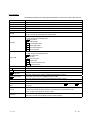
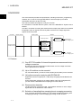
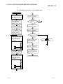
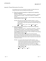
3 SPECIFICATIONS
MELSEC-ST
3.4 Memory and Parameters
This section explains the memory and parameters of the ST1TD2.
3.4.1 Memory
RAM and ROM are available as the parameter storage memory of the ST1TD2.
(1) RAM
(a)
The ST1TD2 operates based on the parameter settings stored in the RAM.
(b)
The parameter settings stored in the RAM become valid when the Bw.n+1
convert setting request turns from OFF to ON.
(2) ROM
3 - 24
(a)
The ROM stores the parameters. The stored parameters are not erased at
power-off.
(b)
The parameters stored in the ROM are transferred to the RAM when:
• The MELSEC-ST system (ST1TD2) is powered off, then on.
• The head module is reset.
• Parameter setting ROM read (command number: 3300H) is executed.
3 - 24
3 SPECIFICATIONS
MELSEC-ST
3.4.2 Parameters
The ST1TD2 has user parameters and command parameters.
(1) User parameters
(a) Setting item
• Input type setting
• Offset/gain value selection
• Cold junction temperature compensation setting
(b) Setting method
Set the parameters using the configuration software of the master station.
When the MELSEC-ST system is tested alone, set the parameters using
GX Configurator-ST.
(2) Command parameters
(a) Setting item
• Conversion enable/disable setting
• Sampling process/averaging process specification
• Time/count averaging specification
• Average time/average number of times setting
• Alarm output setting
• Upper upper limit value/upper lower limit value/lower upper limit
value/lower lower limit value setting
• Sensor compensation value setting
(b) Setting method
1) Command
Execute a command from the master station to write the settings to the
RAM of the ST1TD2.
When the command parameters are written in advance using
Parameter setting ROM write (command number: 3301H), master
station program steps can be reduced.
2) GX Configurator-ST
Use of GX Configurator-ST allows the parameters to be easily set onscreen, reducing master station program steps.
Write and save the settings, which are used for a MELSEC-ST system
startup, to the ROM. (Use write to RAM when conducting a test
temporarily.)
3 - 25
3 - 25
4 SETUP AND PROCEDURES BEFORE OPERATION
MELSEC-ST
4 SETUP AND PROCEDURES BEFORE OPERATION
4.1 Handling Precautions
(1) Do not drop the module or give it hard impact since its case is made of resin.
Doing so can damage the module.
(2) Do not disassemble or modify the modules.
Doing so could cause failure, malfunction, injury or fire.
(3) Be careful not to let foreign particles such as swarf or wire chips enter the module.
They may cause a fire, mechanical failure or malfunction.
4
4-1
4-1
4 SETUP AND PROCEDURES BEFORE OPERATION
MELSEC-ST
4.2 Setup and Procedure before Operation
Start
Module mounting
Mount the ST1TD2 onto the base module.
Wiring
Connect external devices to the ST1TD2 (see
Section 4.4).
User parameter setting
Set the user parameters using the configuration
software of the master station. *1 *2
4
When not using GX Configurator-ST
When using GX Configurator-ST
Use factory default
Use factory default
Use user range settings?
Use user range settings
Offset/gain setting
Use user range settings
Offset/gain setting
When using the user range setting, make
offset/gain setting with GX Configurator-ST (see
Section 5.6).
When using the user range setting, make
offset/gain setting with the master station
program (see Section 4.5).
Command parameter setting
Set the command parameters using
GX Configurator-ST (see Section 5.3).
Programming and debbugging
Create a program and check it (see Chapter 6).
Command parameter setting, programming,
debugging
Create a program and check it (including
command parameter setting with the command)
(see Chapter 6).
*1 When using the user range setting, set the offset/gain value selection (user parameter) as "user range setting".
*2 If executing offset / gain setting in the program, set the input type setting (user parameter) appropreate for the offset/gain setting.
(If making the offset / gain setting with GX Configurator-ST, set the input type using GX Configurator-ST.)
POINT
Refer to Section 3.4 for details of the user parameter and command parameter.
4-2
4-2
4 SETUP AND PROCEDURES BEFORE OPERATION
MELSEC-ST
4.3 Part Names
The name of each part in the ST1TD2 is listed below.
The following shows the ST1TD2 mounted on the spring clamp type base module.
4)
1)
2)
ST1TD2
RUN
[Rear view of ST1TD2]
ERR.
CH.
1
2
11
21
+
-
5)
TC
TC
+
-
14
24
4)
No.
4-3
11
21
12
22
13
23
14
24
3)
Name and
appearance
Description
RUN LED and ERR. LED (on/flashing/off) indicate various statuses of
the ST1TD2 (see section 4.3.1).
1)
RUN LED
2)
ERR. LED
3)
Terminal block
The input signal wires of the ST1TD2 are connected to the terminal
block of the base module.
[Applicable base modules]
Spring Clamp Type : ST1B-S4TD2
Screw Clamp Type : ST1B-E4TD2
4)
Slice module
fixing hooks
(at both ends)
Used for mounting/dismounting the ST1TD2 to/from the base module.
While pressing the hooks at both ends, mount/dismount the ST1TD2.
5)
Coding element Prevents the module from being mounted incorrectly.
The coding element consists of two pieces, and its shape varies
depending on the model name.
When the ST1TD2 is mounted on the base module and then
dismounted, one piece of the coding element remains on the base
module, and the other remains on the ST1TD2.
The ST1TD2 can be mounted onto the base module only when the
two pieces of the coding elements are matched.
[Applicable coding element]
ST1TD2 : ST1A-CKY-16
4-3
4 SETUP AND PROCEDURES BEFORE OPERATION
MELSEC-ST
POINT
In order to ensure safety, make sure to attach the coding element to the base
module and ST1TD2.
Terminal No.
Signal name
11
CH1
12
Terminal No.
TC+
21
Vacancy
13
22
Vacancy
14
CH2
23
TC+
24
Signal name
CH1
TC-
Vacancy
Vacancy
CH2
TC-
4.3.1 Status confirmation by LED
Table 4.1 explains the LED indications.
Table 4.1 LED Indications
LED indication
RUN LED
On
Operating status
ERR.LED
Off
Normal
On
System error is occurring
The data communication has stopped or the parameter communication is faulty between
Off
Flashing
the master module and head module, other slice module is faulty or an internal bus error
is occurring.
(1s interval)
System error is occurring when the data communication has stopped or the parameter
On
communication is faulty between the master module and head module, other slice module
is faulty or an internal bus error has occurred.
Flashing
Off
Module is in offset/gain setting mode.
(0.5s interval)
On
System error is occurring in offset/gain setting mode.
Flashing
Off
Module is selected as the target of online module change.
(0.25s interval)
On
System error is occurring when module is selected as the target of online module change.
Off
4-4
Off
Power is off or online module change is being made.
On
System error is occurring during online module change.
4-4
4 SETUP AND PROCEDURES BEFORE OPERATION
MELSEC-ST
4.4 Wiring
The wiring precautions and examples of module connection are provided in this
section.
4.4.1 Wiring precautions
In order to optimize the functions of the ST1TD2 and ensure system reliability, external
wiring, that is protected from noise, is required.
Please observe the following precautions for external wiring:
(1) Use separate cables for the AC control circuit and the external input signals of the
ST1TD2 to avoid the influence of the AC side surges and inductions.
(2) Do not bring/install the cables closer to/together with the main circuit line, a highvoltage cable or a load cable from other than the MELSEC-ST system. Doing so
may increase the effects of noise, surges and induction.
(3) Always place the thermocouple/micro voltage signal cable at least 100mm
(3.94inch) away from the main circuit cables and AC control lines.
Fully keep it away from high-voltage cables and circuits which include harmonics,
such as an inverter's load circuit.
Not doing so will make the module more susceptible to noises, surges and
inductions.
4-5
4-5
4 SETUP AND PROCEDURES BEFORE OPERATION
MELSEC-ST
4.4.2 External wiring
Connect the cables to the base module (sold separately).
(1) Thermocouple
*1
+5V
CH1
11 TC+
12 TCPt1000
-5V
Pt1000
CH2
14 TC+
+5V
*2
*1
24 TC-5V
*2
*1 As cables, always use shielded compensation conductors.
Also, wire the shielded cables as short as possible.
*2 Ground the shield through the cable clamp or terminal block.
Depending on noise conditions, however, it is recommended to ground
the shield on the external device side.
CH1
CH1
CH2
CH2
Connect to the
control panel
When using a
cable clamp
4-6
When using a
terminal block
4-6
4 SETUP AND PROCEDURES BEFORE OPERATION
MELSEC-ST
(2) Micro voltage signal
*1
Load cell
+5V
CH1
11 TC+
12 TCPt1000
-5V
Pt1000
+5V
*2
*1
Load cell
CH2
14 TC+
24 TC-5V
*2
*1 As cables, always use shielded conductors.
Also, wire the shielded cables as short as possible.
*2 Ground the shield through the cable clamp or terminal block.
Depending on noise conditions, however, it is recommended to ground
the shield on the external device side.
CH1
CH1
CH2
CH2
Connect to the
control panel
When using a
cable clamp
When using a
terminal block
POINT
Any channel where no thermocouple, compensation conductor or micro voltage
signal cable is connected must be set to "conversion disable".
If unconnected channel is set as conversion enable, disconnection is detected.
4-7
4-7
4 SETUP AND PROCEDURES BEFORE OPERATION
MELSEC-ST
4.5 Offset/gain Setting
This section explains the offset/gain setting.
(1) The offset/gain setting is a function designed to compensate for the value at any
two points (offset value/gain value) within the operating range when the proper
measured temperature value/micro voltage conversion value is not available at
system startup or when the input type is changed.
(2) The following are the relationships between the measured temperature value/
micro voltage conversion value and respective input value corrected by the offset
value/gain value.
(a) Thermocouple input
Gain value
80[
]
Measured temperature
value is corrected to be input
temperature.
79.7
Measured temperature value
-50[
]
0
80[
]
Input temperature
Measured temperature
value is corrected to be input
temperature.
Characteristic before error compensation
Characteristic after error compensation
-49.7
-50[
]
Offset value
(b) Micro voltage input
Gain value
20000
Micro voltage conversion
value is corrected to be
gain setting.
18975
Micro voltage conversion value
75[mV]
0
80[mV]
Micro voltage input value
Characteristic before error compensation
Characteristic after error compensation
Micro voltage conversion
value is corrected to be
offset setting.
4-8
18723
18750
Offset value
4-8
4 SETUP AND PROCEDURES BEFORE OPERATION
MELSEC-ST
POINT
(1) Make the offset/gain setting within the measured temperature guarantee range
(refer to Section 3.1 (2), or within the measurable voltage range (refer to Section
3.1 (3)). If the setting is made outside these ranges, the resolution and accuracy
may not fall within the ranges of the performance specifications.
(2) Obtain the offset value and gain value in the status of actual use.
After the setting is completed, make sure that the offset value and gain value are
set correctly in the status of actual use.
(3) The offset and gain values are stored into the ROM and are not erased at poweroff.
(4) When making the offset/gain setting, write the values to the ROM using User
range write (command number: 3305H). Data can be written to the ROM up to
10,000 times.
To prevent accidental write to the ROM, write to ROM is counted from the time of
power-on.
(5) If an error occurs during offset/gain setting, the offset and gain values are not
written to the ST1TD2.
Set the correct offset and gain values again.
(6) High accuracy is ensured when the offset and gain values are set as the
minimum and maximum values of the operating range.
(7) High accuracy can be obtained if the offset/gain setting is done after 30-minute
power-up.
(8) Always set the offset and gain values so that they will satisfy the following
conditions. An error will occur if any of the conditions are not satisfied.
Condition 1: Within the input enabled range
Condition 2: Offset value < Gain value
Condition 3: (Gain value) - (offset value) > 0.2 [ ] (for temperature input)
or (Gain value) - (offset value) > 20 [ V] (for micro voltage input)
(9) For thermocouple input, error compensation may also be made using a standard
DC voltage generator or like instead of inputting a temperature directly to the
thermocouple.
Power value of standard
DC voltage generator
4-9
=
Thermoelectromotive force value of thermocouple used
as offset/gain value relative to input temperature
4-9
4 SETUP AND PROCEDURES BEFORE OPERATION
MELSEC-ST
4.5.1 Offset/gain settings procedure
If using the user range setting, perform the offset/gain setting in the procedure shown
in the section 4.5.1(1) or 4.5.1(2).
When the factory default is used, the offset/gain setting is not necessary.
If the GX Configurator-ST has been installed, perform the offset/gain settings
according to the procedure described in Section 5.6.
(1) Offset/gain setting for thermocouple input
Start
1)
3)
Set the input type setting
(user parameter) as "The
input type to perform offset/
gain setting"
Input the gain value in the
adjusting channel, and then
execute gain channel
specification. (command
no. : 3304H)
Confirm that the command
execution is completed.
Confirm that the ST1TD2
is in the normal mode. (In
this mode, the ST1TD2
RUN LED is on.)
ST1TD2
Set "Yes" to the cold
junction temperature
compensation setting
(user parameter).*
ST1TD2
ERR.
RUN
CH.
1
2
11 21
+
-
1C
1C
+
-
14 24
Thermcouple
500[
Execute operation mode
setting (command no.:
3302H) to shift to the
offset/gain setting mode.
]
Alternatively, enter the value
using a standard DC voltage
generator or the like.
11
21
12
22
13
23
14
24
Confirm that the command
execution is completed.
Confirm that the command
execution is completed.
Confirm that the ST1TD2
is in the offset/gain setting
mode. (In this mode, the
ST1TD2 RUN LED is
flashing at 0.5s intervals.)
Adjust other
channels?
2)
Input the offset value in the
adjusting channel, and then
execute offset channel
specification (command
no. : 3303H)
End
YES
2)
NO
Execute user range write
(command no.: 3305H).
Confirm that the command
execution is completed.
ST1TD2
ST1TD2
ERR.
RUN
CH.
1
2
11 21
+
-
1C
1C
+
-
14 24
Is the ST1TD2
ERR. LED on?
YES
Thermcouple
0[
]
Alternatively, enter the value
using a standard DC voltage
generator or the like.
11
21
12
22
13
23
14
24
Confirm that the command
execution is completed.
1)
NO
Execute operation mode
setting (command no.:
3302H) to shift to the
normal mode.
3)
Turn on Ew.n error clear
request to clear errors.
2)
* When inputting a value with a standard D/C voltage generator or when actually
using the module with the cold junction temperature compensation setting set to
"No", set the cold junction temperature compensation setting to "No".
4 - 10
4 - 10
4 SETUP AND PROCEDURES BEFORE OPERATION
MELSEC-ST
(2) Offset/gain setting for micro voltage input
1)
Start
Set the input type setting
(user parameter) as "The
input type to perform offset/
gain setting"
Execute operation mode
setting (command no.:
3302H) to shift to the
offset/gain setting mode.
Confirm that the command
execution is completed.
Adjust other
channels?
YES
2)
NO
Confirm that the command
execution is completed.
Confirm that the ST1TD2
is in the offset/gain setting
mode. (In this mode, the
ST1TD2 RUN LED is
flashing at 0.5s intervals.)
Execute user range write
(command no.: 3305H).
Confirm that the command
execution is completed.
Is the ST1TD2
ERR. LED on?
2)
Input the offset value in the
adjusting channel, and then
execute offset channel
specification (command
no. : 3303H).
ST1TD2
ST1TD2
ERR.
RUN
YES
NO
Execute operation mode
setting (command no.:
3302H) to shift to the
normal mode.
Turn on Ew.n error clear
request to clear errors.
CH.
1
2
11 21
+
-
1C
1C
+
-80[mV]
-
14 24
Load cell or like
11
21
12
22
13
23
14
24
Confirm that the command
execution is completed.
Input the gain value in the
adjusting channel, and then
execute gain channel
specification (Command
no. : 3304H).
Confirm that the command
execution is completed.
2)
Confirm that the ST1TD2
is in the normal mode. (In
this mode, the ST1TD2
RUN LED is on.)
End
ST1TD2
ST1TD2
ERR.
RUN
CH.
1
2
11 21
+
-
1C
1C
+
80[mV]
-
14 24
11
Load cell or like
21
12
22
13
23
14
24
1)
4 - 11
4 - 11
4 SETUP AND PROCEDURES BEFORE OPERATION
MELSEC-ST
(3) Programming
The program examples are given in this section, showing the mode switching
(between the normal mode and the offset/gain setting mode), the channel
specification for the offset/gain setting, the offset/gain value adjustment, and the
offset/gain value writing to the ST1TD2.
(a) When QJ71PB92D is used as master station
The program example is based on the system configuration given in
Section 6.2.
1) Device assignment in program examples
Devices used by QJ71PB92D
Device
Application
Device
X0
Exchange start end signal
Y0
X1B
Communication READY signal
X1D
Module READY signal
X1F
Watchdog timer error signal
Application
Exchange start request signal
Devices used by user
Device
Application
Device
X20
PROFIBUS-DP exchange start command
X25
Offset/gain setting mode select signal
X26
Offset channel specification signal
X27
Gain channel specification signal
X28
User range write signal
X29
Normal mode select signal
M0
Application
Refresh start request
Devices used in I/O data
Br Bit input area
Br.n Bit input
Information
Master station side device
Br.00
Module READY
D1000.0
Br.01
Forced output test mode
D1000.1
Br.02
Module name
0
ST1H-PB
Module being changed
D1000.2
online
Br.03
Command execution
D1000.3
Br.04
External power supply
D1000.4
Br.05
status
D1000.5
Br.06
Module ready
D1000.6
Br.07
Slice No.
Convert setting completed
D1000.7
flag
Br.08
Conversion completed flag
D1000.8
Br.09
Alarm output signal
D1000.9
Br.0A
1
2
ST1PSD
3
ST1TD2
4
D1000.A
to
Br.1F
4 - 12
D1001.F
4 - 12
4 SETUP AND PROCEDURES BEFORE OPERATION
MELSEC-ST
Er Error information area
Er.n Error information
Information
Master station side device
Er.00
D1002.0
Er.01
Head module error
D1002.1
Er.02
information
D1002.2
Er.03
Bus refreshing module
D1002.4
Er.05
error information
D1002.5
Er.07
Er.08
Er.09
ST1H-PB
1
2
D1002.6
CH1 error information
ST1TD2
D1002.8
4
D1002.9
Er.0A
ST1PSD
3
D1002.7
CH2 error information
Module name
0
D1002.3
Er.04
Er.06
Slice No.
D1002.A
to
Er.1F
D1003.F
Mr Module status area
Mr.n Module status
Information
Master station side device
Slice No.
Mr. 0
Head module existence
D1004.0
0
Mr. 1
information
D1004.1
1
D1004.2
2
D1004.3
3
D1004.4
4
Mr.2
Mr.3
Mr.4
Bus refreshing module
existence information
Module status
Mr.5
Module name
ST1H-PB
ST1PSD
ST1TD2
D1004.5
to
Mr.15
D1004.F
Cr Command result area
Information
Master station side
device
Slice No.
Module name
Cr.0(15-8) Command Execution
Cr.0
Result, Cr.0(7-0) Start Slice No. of
D1005
Execution Target
4 - 13
Cr.1
Executed Command No.
D1006
Cr.2
Response Data 1
D1007
Cr.3
Response Data 2
D1008
4 - 13
4 SETUP AND PROCEDURES BEFORE OPERATION
MELSEC-ST
Bw Bit output area
Bw.n Bit output
Information
Master station side device
Bw.00
System area (0 fixed)
D2000.0
Bw.01
System area (0 fixed)
D2000.1
Bw.02
System area (0 fixed)
D2000.2
Bw.03
Command request
D2000.3
Bw.04
System area (0 fixed)
D2000.4
Bw.05
System area (0 fixed)
D2000.5
Bw.06
System area (0 fixed)
D2000.6
Bw.07
Convert setting request
D2000.7
Bw.08
System area (0 fixed)
D2000.8
Bw.09
System area (0 fixed)
D2000.9
Bw.0A
Slice No.
Module name
0
ST1H-PB
1
2
ST1PSD
3
ST1TD2
4
D2000.A
to
Bw.1F
D2001.F
Ew Error clear area
Ew.n Error clear
Information
Master station side device
Ew.00
Error clear request
D2002.0
Ew.01
System area (0 fixed)
D2002.1
Ew.02
System area (0 fixed)
D2002.2
Ew.03
System area (0 fixed)
D2002.3
Ew.04
Error clear request
D2002.4
Ew.05
System area (0 fixed)
D2002.5
Ew.06
Error clear request
D2002.6
Ew.07
System area (0 fixed)
D2002.7
Ew.08
System area (0 fixed)
D2002.8
Ew.09
System area (0 fixed)
D2002.9
Ew.0A
Slice No.
Module name
0
ST1H-PB
1
2
ST1PSD
3
ST1TD2
4
D2002.A
to
Ew.1F
4 - 14
D2003.F
4 - 14
4 SETUP AND PROCEDURES BEFORE OPERATION
MELSEC-ST
Sw System area
Sw System area
Sw.0
Information
System area (0 fixed)
Master station side device
Slice No.
Module name
Slice No.
Module name
D2004
Cw Command execution area
Cw Command execution
area
Cw.0
Cw.1
4 - 15
Information
Start Slice No. of
Execution Target
Command No. to be
Executed
Master station side device
D2005
D2006
Cw.2
Argument 1
D2007
Cw.3
Argument 2
D2008
4 - 15
4 SETUP AND PROCEDURES BEFORE OPERATION
MELSEC-ST
2) Program example
FDL address 1
initial data write
PROFIBUS-DP
communication
start processing
Switching to offset/gain setting mode
Br.00
Br.06
Br.03
Bw.03
Turns on Bw.03
command request
Bw.03
Cw.0 start slice
no. of execution
target
Cw.1 command
no. to be
executed(3302H)
Cw.2 argument 1
Cw.3 argument 2
Offset Channel Specification
Br.00
Br.06
Br.03
Bw.03
Bw.03
Turns on Bw.03
command request
Cw.0 start slice
no. of execution
target
Cw.1 command
no. to be
executed(3303H)
Cw.2 argument 1
Cw.3 argument 2
4 - 16
4 - 16
4 SETUP AND PROCEDURES BEFORE OPERATION
MELSEC-ST
Gain Channel Specification
Br.00
Br.06
Br.03
Bw.03
Bw.03
Turns on Bw.03
command request
Cw.0 start slice
no. of execution
target
Cw.1 command
no. to be
executed(3304H)
Cw.2 argument 1
Cw.3 argument 2
User Range Write
Br.00
Br.06
Br.03
Bw.03
Turns on Bw.03
command request
Bw.03
Cw.0 start slice
no. of execution
target
Cw.1 command
no. to be
executed(3305H)
Cw.2 argument 1
Cw.3 argument 2
4 - 17
4 - 17
4 SETUP AND PROCEDURES BEFORE OPERATION
MELSEC-ST
Switching to normal mode
Br.00
Br.06
Br.03
Bw.03
Bw.03
Turns on Bw.03
command request
Cw.0 start slice
no. of execution
target
Cw.1 command
no. to be
executed(3302H)
Cw.2 argument 1
Cw.3 argument 2
Command execution processing
Br.03
Bw.03
Turns off Bw.03
command request
Command execution result error
processing
Command execution result error
processing
Command execution result error
processing
Command execution result error
processing
4 - 18
4 - 18
4 SETUP AND PROCEDURES BEFORE OPERATION
MELSEC-ST
(b) When AJ71PB92D/A1SJ71PB92D is used as master station
The program example is based on the system configuration given in
Section 6.3.
1) Device assignment in program examples
Devices used by A1SJ71PB92D
Device
Application
Device
X0
Exchange start end signal
Y0
X0D
Watchdog timer error signal
X1B
Communication READY signal
X1D
Module READY signal
Application
Exchange start request signal
Devices used by user
Device
Application
Device
X20
PROFIBUS-DP exchange start command
M0
X25
Offset/gain setting mode select signal
M225
X26
Offset channel specification signal
M226
X27
Gain channel specification signal
M227
X28
User range write signal
M228
X29
Normal mode select signal
M229
Application
Refresh start request
Conversion of offset/gain setting mode
select signal into pulse
Conversion of offset channel specification
signal into pulse
Conversion of gain channel specification
signal into pulse
Conversion of user range write signal into
pulse
Conversion of normal mode select signal
into pulse
Devices used in I/O data
Br Bit input area
Br.n Bit input
Information
Master station side device
Br.00
Module READY
B0
Br.01
Forced output test mode
B1
Br.02
Module name
0
ST1H-PB
Module being changed
B2
online
Br.03
Command execution
B3
Br.04
External power supply
B4
Br.05
status
B5
Br.06
Module ready
B6
Br.07
Slice No.
Convert setting completed
B7
flag
Br.08
Conversion completed flag
B8
Br.09
Alarm output signal
B9
Br.0A
1
2
ST1PSD
3
ST1TD2
4
BA
to
Br.1F
4 - 19
B1F
4 - 19
4 SETUP AND PROCEDURES BEFORE OPERATION
MELSEC-ST
Er Error information area
Er.n Error information
Information
Master station side device
Er.00
B20
Er.01
Head module error
B21
Er.02
information
B22
Er.03
Bus refreshing module
B24
Er.05
error information
B25
Er.07
Er.08
Er.09
ST1H-PB
1
2
B26
CH1 error information
ST1TD2
B28
4
B29
Er.0A
ST1PSD
3
B27
CH2 error information
Module name
0
B23
Er.04
Er.06
Slice No.
B2A
to
Er.1F
B3F
Mr Module status area
Mr.n Module status
Information
Master station side device
Slice No.
Mr. 0
Head module existence
B40
0
Mr. 1
information
B41
1
B42
2
B43
3
B44
4
Mr.2
Mr.3
Mr.4
Bus refreshing module
existence information
Module status
Mr.5
Module name
ST1H-PB
ST1PSD
ST1TD2
B45
to
Mr.15
B5F
Cr Command result area
Information
Master station side
device
Slice No.
Module name
Cr.0(15-8) Command Execution
Cr.0
Result, Cr.0(7-0) Start Slice No. of
W0
Execution Target
4 - 20
Cr.1
Executed Command No.
W1
Cr.2
Response Data 1
W2
Cr.3
Response Data 2
W3
4 - 20
4 SETUP AND PROCEDURES BEFORE OPERATION
MELSEC-ST
Bw Bit output area
Bw.n Bit output
Information
Master station side device
Bw.00
System area (0 fixed)
B1000
Bw.01
System area (0 fixed)
B1001
Bw.02
System area (0 fixed)
B1002
Bw.03
Command request
B1003
Bw.04
System area (0 fixed)
B1004
Bw.05
System area (0 fixed)
B1005
Bw.06
System area (0 fixed)
B1006
Bw.07
Convert setting request
B1007
Bw.08
System area (0 fixed)
B1008
Bw.09
System area (0 fixed)
B1009
Bw.0A
Slice No.
Module name
0
ST1H-PB
1
2
ST1PSD
3
ST1TD2
4
B100A
to
Bw.1F
B101F
Ew Error clear area
Ew.n Error clear
Information
Master station side device
Ew.00
Error clear request
B1020
Ew.01
System area (0 fixed)
B1021
Ew.02
System area (0 fixed)
B1022
Ew.03
System area (0 fixed)
B1023
Ew.04
Error clear request
B1024
Ew.05
System area (0 fixed)
B1025
Ew.06
Error clear request
B1026
Ew.07
System area (0 fixed)
B1027
Ew.08
System area (0 fixed)
B1028
Ew.09
System area (0 fixed)
B1029
Ew.0A
Slice No.
Module name
0
ST1H-PB
1
2
ST1PSD
3
ST1TD2
4
B102A
to
Ew.1F
4 - 21
B103F
4 - 21
4 SETUP AND PROCEDURES BEFORE OPERATION
MELSEC-ST
Sw System area
Sw System area
Sw.0
Information
System area (0 fixed)
Master station side device
Slice No.
Module name
Slice No.
Module name
B1040 to B104F
Cw Command execution area
Cw Command execution
area
Cw.0
Cw.1
4 - 22
Information
Start Slice No. of
Execution Target
Command No. to be
Executed
Master station side device
W1000
W1001
Cw.2
Argument 1
W1002
Cw.3
Argument 2
W1003
4 - 22
4 SETUP AND PROCEDURES BEFORE OPERATION
MELSEC-ST
2) Program example
FDL address 1
initial data write
PROFIBUS-DP
communication
start processing
Input area read
Switching to offset/gain setting mode
Br.00
Br.06
Br.03
Bw.03
Bw.03
Turns on Bw.03
command request
Cw.0 start slice
no. of execution
target
Cw.1 command
no. to be
executed(3302H)
Cw.2 argument 1
Cw.3 argument 2
Offset Channel Specification
Br.00
Br.06
Br.03
Bw.03
Turns on Bw.03
command request
Bw.03
Cw.0 start slice
no. of execution
target
Cw.1 command
no. to be
executed(3303H)
Cw.2 argument 1
Cw.3 argument 2
4 - 23
4 - 23
4 SETUP AND PROCEDURES BEFORE OPERATION
MELSEC-ST
Gain Channel Specification
Br.00
Br.06
Br.03
Bw.03
Bw.03
Turns on Bw.03
command request
Cw.0 start slice
no. of execution
target
Cw.1 command
no. to be
executed(3304H)
Cw.2 argument 1
Cw.3 argument 2
User Range Write
Br.00
Br.06
Br.03
Bw.03
Bw.03
Turns on Bw.03
command request
Cw.0 start slice
no. of execution
target
Cw.1 command
no. to be
executed(3305H)
Cw.2 argument 1
Cw.3 argument 2
4 - 24
4 - 24
4 SETUP AND PROCEDURES BEFORE OPERATION
MELSEC-ST
Switching to normal mode
Br.00
Br.06
Br.03
Bw.03
Bw.03
Turns on Bw.03
command request
Cw.0 start slice
no. of execution
target
Cw.1 command
no. to be
executed(3302H)
Cw.2 argument 1
Cw.3 argument 2
Command execution processing
Br.03
Bw.03
Turns off Bw.03
command request
Command execution result error
processing
Command execution result error
processing
Command execution result error
processing
Command execution result error
processing
Br.00
4 - 25
Output area
write
4 - 25
5 GX Configurator-ST
MELSEC-ST
5 GX Configurator-ST
This chapter explains the functions of GX Configurator-ST used with the ST1TD2.
For details of GX Configurator-ST, refer to the GX Configurator-ST Operating Manual.
5.1 GX Configurator-ST Functions
Table 5.1 lists the GX Configurator-ST functions used with the ST1TD2.
Table 5.1 List of GX Configurator-ST Functions Used with ST1TD2
Item
5
Parameter Setting
Description
(1) The following parameter items can be set on GX Configurator-ST.
• CH input type setting
• CH offset/gain value selection
• CH cold junction compensation
• CH conversion enable/disable setting
• CH time/number of times specification
• CH sampling process/averaging process setting
• CH alarm output setting
• CH average time/average number of times setting
• CH upper upper limit value/upper lower limit value/lower upper
limit value/lower lower limit value
• CH sensor compensation value setting
Reference section
Section 5.3
(2) Specify the area (RAM or ROM) where parameter setting will be
registered.
(3) Using GX Configurator-ST, parameter setting can be made while
online module change is performed.
Input/output monitor
Forced output test
(1) The I/O data of the ST1TD2 can be monitored.
(1) Test can be conducted with the values set in the Bw bit output
area or Ew error clear area of the ST1TD2.
Section 5.4
Section 5.5
(1) The offset and gain values of the user range can be easily set onOffset/gain setting
screen.
(2) Using GX Configurator-ST, gain/offset setting can be made while
Section 5.6
online module change is performed.
Online module change
5-1
(1) A module can be replaced without the system being stopped.
Chapter 7
5-1
5 GX Configurator-ST
MELSEC-ST
5.2 Project Creation
When the MELSEC-ST system can be connected to a personal computer with GX
Configurator-ST preinstalled, select [get system] to create a project.
Even if there is no MELSEC-ST system, a project can be created.
For project creation and get system, refer to the GX Configurator-ST Operating
Manual.
5
5-2
5-2
5 GX Configurator-ST
MELSEC-ST
5.3 Parameter Setting
This section explains how to set the parameters.
(1) Mode changing
The mode need not be changed.
Either the edit mode or diagnosis mode can be used for the setting.
(2) Displaying "Parameter Setting" screen
1)
2)
Select ST1TD2 on the "Module Information List" screen or "System Monitor"
screen.
Click [Edit] [Parameter Setting].
(3) Display/Setting Screen
5-3
5-3
5 GX Configurator-ST
MELSEC-ST
(4) Display/setting details
When setting the parameters of multiple channels, make the following setting for
each channel.
(a) User parameters
Set the user parameters using the configuration software of the master
station.
When the MELSEC-ST system is tested alone, set the parameters using
GX Configurator-ST.
1) Input type setting
Set the input type.
Select the input type from among the following types.
Input type
Measured temperature
Thermocouple K
Thermocouple E
Thermocouple J
Thermocouple T
Thermocouple B
Thermocouple R
Thermocouple S
Thermocouple N
Micro voltage input
-270 to 1372°C
-270 to 1000°C
-210 to 1200°C
-270 to 400°C
0 to 1820°C
-50 to 1768°C
-50 to 1768°C
-270 to 1300°C
-80 to 80mV
2) Setting type
The input type setting currently valid is stored.
Setting is not allowed.
3) Offset/gain value selection
Set the factory default or user range setting.
4) Cold junction compensation
Set whether cold junction temperature compensation is enable or
disable.
Disable : Cold junction temperature compensation disabled
Enable : Cold junction temperature compensation enabled
(b) Command parameters
By setting the command parameters using GX Configurator-ST, master
station program steps can be reduced.
Write and save the settings, which are used for a MELSEC-ST system
startup, to the ROM. (Use RAM when conducting a test temporarily.)
1) Conversion enable/disable setting
Set whether conversion is enabled or disabled.
Disable : Conversion disabled
Enable : Conversion enabled
2) Time/number of times specification
Specify the time/number of times when the averaging processing is
selected.
3) Sampling process/averaging process setting
Specify the sampling processing or averaging processing.
5-4
5-4
5 GX Configurator-ST
MELSEC-ST
4) Alarm output setting
Set whether alarm output processing is performed or not.
Disable : Alarm output processing not performed
Enable : Alarm output processing performed
5) Average time/average number of times setting
Set the average time or average number of times.
Their setting ranges are indicated below.
Average number of times : 4 to 500 times
Average time
: 480 to 5000ms
6) Upper upper limit value/Upper lower limit value/Lower
upper limit value/Lower lower limit value
Set the upper upper limit value, upper lower limit value, lower upper
limit value and lower lower limit value of the alarm output.
Setting range on each input type is shown below.
In the case of thermocouple input, set the value in units of 0.1 .
[Example] To set to 0.3 ..... Enter "3".
Input type
Setting range (Accuracy guarantee range)
Thermocouple K
-2700 to 13720 (-2000 to 12000)
Thermocouple E
-2700 to 10000 (-2000 to 9000)
Thermocouple J
-2100 to 12000 (-400 to 7500)
Thermocouple T
-2700 to 4000 (-2000 to 3500)
Thermocouple B
0 to 18200 (6000 to 17000)
Thermocouple R
-500 to 17680 (0 to 16000)
Thermocouple S
-500 to 17680 (0 to 16000)
Thermocouple N
-2700 to 13000 (-2000 to 12500)
Micro voltage input
-21000 to 21000 (-20000 to 20000)
7) Sensor compensation value setting
Set the sensor compensation value.
The setting range of the sensor compensation value is –500 to 500.
In the case of thermocouple input, set the value in units of 0.1 .
[Example] To set to 0.3 ..... Enter "3".
The setting for the micro voltage input is performed in increments of
4µV/digit.
[Example] When the micro voltage conversion value is 10003 at 40mV
input ..... Enter “-3”.
5-5
5-5
5 GX Configurator-ST
MELSEC-ST
(5) Parameter writing
1) From the "Channel:" pull-down menu, select the channel where the
parameters will be set.
2) Select the parameter items to be written to the ST1TD2 by checking the
corresponding "select" check box.
3) Make setting in the "Setting Value" field.
4) Select the target memory (RAM or ROM) from the pull-down menu of "Target
Memory".
5) Click the Download button.
When writing the parameters of multiple channels to the ST1TD2, perform the
operations in steps 1) to 5) for each channel.
5-6
5-6
5 GX Configurator-ST
MELSEC-ST
5.4 Input/Output Monitor
This section explains how to monitor the I/O data of the ST1TD2.
(1) Mode changing
Click [Mode]
[Diagnosis].
(2) Displaying "Input/Output Monitor" screen
1) Select ST1TD2 on the "System Monitor" screen.
2) Click the Input/Output Monitor button.
Monitor starts as soon as the "Input/Output Monitor" screen is displayed.
(3) Display/Setting Screen
(4) Display/setting details
(a) Bit Data
Input/Output Data
Item
Description
Bit Output Area
Convert setting request
The status of Bw.n+1 Convert setting request is displayed.
Error Clear Area
Error clear request
The status of Ew.n Error clear request is displayed.
Module ready
The status of Br.n Module ready is displayed.
Convert setting completed flag
Bit Input Area
Conversion completed flag
Alarm output signal
Error Information Area
CH
error information
The status of Br.n+1 Convert setting completed flag is
displayed.
The status of Br.n+2 Conversion completed flag is
displayed.
The status of Br.n+3 Alarm output signal is displated.
The status of Er.n+3 to Er.n CH
displayed.
error information is
(b) Word Data
The display format (decimal/hexadecimal) can be changed.
Input/Output Data
Word Input Area
5-7
Item
CH measured temperature
value/micro voltage value
Description
The value of Wr.n , Wr.n+1 CH measured temperature
value/micro voltage value is displayed.
5-7
5 GX Configurator-ST
MELSEC-ST
5.5 Forced Output Test
This section explains a forced output test.
Conduct the test after setting values to the bit output area or error clear area of the
ST1TD2.
(1) Mode changing
Click [Mode]
[Diagnosis].
(2) Displaying "Forced Output Test" screen
1) Select ST1TD2 on the "System Monitor" screen.
2) Click the Forced Output Test button.
(3) Display/Setting Screen
(4) Display/setting details
(a) Bit Data
Output Data
Item
Bit Output Area
Convert setting request
Error Clear Area
Error clear request
Description
The setting of Bw.n+1 Convert setting request can be
changed.
The setting of Ew.n Error clear request can be
changed.
(b) Word Data
Unavailable for the ST1TD2.
5-8
5-8
5 GX Configurator-ST
MELSEC-ST
(5) Test operation
1) Select the test item by checking the corresponding "Select" check box.
2) Make setting in the "Value" field.
3) Click the Settings button.
Clicking the Settings button executes the test.
: When the module is not in the forced output test mode, a screen asking
whether to switch to the forced output test mode. Click the OK button to
switch to the forced output test mode.
When the module is switched to the forced output test mode, the RUN
LED of the head module flashes.
POINT
When the forced output test mode has been cancelled, make sure that the RUN
LED of the head module is on.
5-9
5-9
5 GX Configurator-ST
MELSEC-ST
5.6 Offset/Gain Setting
This section explains how to make offset/gain setting.
(1) Input type setting
Set the input type for the offset/gain setting on the parameter setting screen.
For the parameter setting, refer to Section 5.3.
(2) Mode changing
Click [Mode]
[Diagnosis].
(3) Displaying "Offset/Gain Setting" screen
1) Select ST1TD2 on the "System Monitor" screen.
2) Click the Offset/Gain Setting button.
: When the module is not in the forced output test mode, a screen appears
asking whether to switch to the forced output test mode. Click the OK
button to switch to the forced output test mode.
When the module is switched to the forced output test mode, the RUN
LED of the head module flashes.
3) As a screen appears asking whether to switch to the offset/gain setting
mode, click the OK button to switch to the offset/gain setting mode.
After switched to the offset/gain setting mode, the RUN LED of ST1TD2
flashes (0.5s interval) and the ST1TD2 stops.
(4) Display/Setting Screen
5 - 10
5 - 10
5 GX Configurator-ST
MELSEC-ST
(5) Offset/gain setting
When setting different offset and gain values for different channels, perform the
operations in (a), (b) for each channel.
Since the operation in (c) is to be done to write the offset/gain settings of all
channels to the ST1TD2, perform it only once at the last.
(a) Offset value setting operation
1)
2)
3)
Select the channel where the offset value will be set by checking the
corresponding "Select channel" check box.
By checking multiple check boxes, values can be set to multiple
channels at the same time.
Specify "Offset".
Enter a value as an offset value to the channel to be adjusted, set a
temperature setting value or voltage setting value which suits to input,
and then click the Set button.
• The setting for the temperature setting value is performed in units of
0.1 .
[Example] To set to 0.3 ..... Enter "3".
• The setting for the voltage setting value is performed in units of
0.01mV.
[Example] To set to 3mV ..... Enter "300".
Setting range on each input type is shown below.
Input type
Setting range (Accuracy guarantee range)
Thermocouple K
-2700 to 13720 (-2000 to 12000)
Thermocouple E
-2700 to 10000 (-2000 to 9000)
Thermocouple J
-2100 to 12000 (-400 to 7500)
Thermocouple T
-2700 to 4000 (-2000 to 3500)
Thermocouple B
0 to 18200 (6000 to 17000)
Thermocouple R
-500 to 17680 (0 to 16000)
Thermocouple S
-500 to 17680 (0 to 16000)
Thermocouple N
-2700 to 13000 (-2000 to 12500)
Micro voltage input
-8000 to 8000 (-8000 to 8000)
(b) Gain value setting
1)
2)
5 - 11
Select the channel where the gain value will be set by checking the
corresponding "Select channel" check box.
By checking multiple check boxes, values can be set to multiple
channels at the same time.
Specify "Gain".
5 - 11
5 GX Configurator-ST
MELSEC-ST
3)
Enter a value as a gain value to the channel to be adjusted, set a
temperature setting value or voltage setting value which suits to input,
and then click the Set button.
• The setting for the temperature setting value is performed in units of
0.1 .
[Example] To set to 0.3 .....Enter "3".
• The setting for the voltage setting value is performed in units of
0.01mV.
[Example] To set to 3mV ..... Enter "300".
Setting range on each input type is shown below.
Input type
Setting range (Accuracy guarantee range)
Thermocouple K
-2700 to 13720 (-2000 to 12000)
Thermocouple E
-2700 to 10000 (-2000 to 9000)
Thermocouple J
-2100 to 12000 (-400 to 7500)
Thermocouple T
-2700 to 4000 (-2000 to 3500)
Thermocouple B
0 to 18200 (6000 to 17000)
Thermocouple R
-500 to 17680 (0 to 16000)
Thermocouple S
-500 to 17680 (0 to 16000)
Thermocouple N
-2700 to 13000 (-2000 to 12500)
Micro voltage input
-8000 to 8000 (-8000 to 8000)
(c) Offset/gain setting writing
Click the Save button.
The offset/gain settings for all channels are written to the ST1TD2.
POINT
(1) Clicking the Save button in the following condition generates errors.
For details of error codes, refer to Section 9.1.
• Offset value ≥ Gain value (Error code : 400 H)
• (Gain value) - (Offset value) ≤ 0.2[ ] (for temperature input)
(Error code : 410 H)
• (Gain value) - (Offset value) ≤ 20[ V] (for micro voltage input)
(Error code : 410 H)
In this case, click the Error Clear button to clear the error, and make setting
again.
(2) When the offset/gain setting screen is closed, the screen displays a message
that asks if you are sure to change to the normal mode. Click the OK button
to change to the normal mode.
When the module is put in the normal mode, the RUN LED of the ST1TD2
turns on.
(3) When the forced output test mode has been released, make sure that the RUN
LED of the head module is on.
5 - 12
5 - 12
6 PROGRAMMING
MELSEC-ST
6 PROGRAMMING
This chapter explains program examples available when the QJ71PB92D and
AJ71PB92D/A2SJ71PB92D are used as the master station.
REMARK
Refer to the following manuals for details of the QJ71PB92D and
AJ71PB92D/A1SJ71PB92D.
<QJ71PB92D>
PROFIBUS-DP Interface Module User's Manual
SH-080127 (13JR22)
<AJ71PB92D/A1SJ71PB92D>
PROFIBUS-DP Interface Module type AJ71PB92D/A1SJ71PB92D User's
Manual
IB-66773 (13JL20)
6
6-1
6-1
6 PROGRAMMING
MELSEC-ST
6.1 Programming Procedure
In the following procedure, create a program enabling execution of the temperature
conversion or micro voltage conversion in the ST1TD2.
When utilizing the program example introduced in this chapter for an actual system,
fully verify that there are no problems in controllability in the target system.
Start
When using GX Configurator-ST
Set the command parameter using GX
Configurator-ST.(see Section 5.3)
Bw.n+1 Convert setting request
Read measured temperature value/micro
voltage conversion value
End
When not using GX Configurator-ST
Conversion enable/disable setting
(see Section 8.4.1)
NO
Is averaging process performed?
YES
Sampling process/averaging process
specification (see Section 8.4.2)
Time/count averaging specification
(see Section 8.4.2)
Average time/Average number of times
setting (see Section 8.4.3)
6
Is alarm output?
NO
YES
Alarm output setting (see Section 8.4.2)
Upper upper limit value/upper lower limit
value/lower upper limit value/lower lower limit
value setting (see Section 8.4.4, 8.4.5)
Bw.n+1 Convert setting request
Read measured temperature value/micro
voltage conversion value
End
6-2
6-2
6 PROGRAMMING
MELSEC-ST
POINT
(1) While a command is being executed, other command is not executable.
Also, a command can be executed for only one module.
When executing the same command for multiple modules or executing several
kinds of commands, provide an interlock in the program using
Br.03 Command execution and Bw.03 Command request as shown below.
<Example>
Executing 2 commands (Commands 1 and 2) consecutively
1) Confirm that Br.03 Command execution and Bw.03 Command
request are off. (Interlock for other commands)
2) Write the command information of Command 1 to Cw Command
execution area.
3) Turn on Bw.03 Command request.
Processing of
Command 1
4) After Br.03 Command execution turns on, read the result of
Command 1 from Cr Command result area.
5) Turn off Bw.03 Command request.
6) Confirm that Br.03 Command execution and Bw.03 Command
request are off. (Interlock for other commands)
7) Write the command information of Command 2 to Cw Command
execution area.
8) Turn on Bw.03 Command request.
Processing of
Command 2
9) After Br.03 Command execution turns on, read the result of
Command 2 from Cr Command result area.
10)Turn off Bw.03 Command request.
If a command is executed without any interlock, the following status will be
generated.
1) When turning off Bw.03 Command request before completion of the
command:
• Br.03 Command execution does not turn on.
• The command result is not stored in Cr Command result area.
• The command requested once may be executed.
2) When executing a command inadvertently during execution of other
command:
The command is executed based on the information written in Cw
Command execution area at the time that Bw.03 Command request
turns on.
(2) Performing online module change may require a previous arrangement,
depending on the use condition.
For details, refer to Section 7.2.
6-3
6-3
6 PROGRAMMING
MELSEC-ST
6.2 When QJ71PB92D is Used as Master Station
This section explains program examples available when the QJ71PB92D is used as
the master station.
Section 6.2.1 uses the following system configuration example for explanation.
(1) System configuration of master station (QJ71PB92D)
The system configuration of the master station (QJ71PB92D) used in this section
is shown below.
(a) System configuration of master station (QJ71PB92D)
Q25HCPU
QJ71PB92D
QX42
(b) Settings of master station (QJ71PB92D)
Item
I/O signals
Operation mode
I/O data area (buffer memory) for FDL
address 1 (MELSEC-ST system)
Input data
Output data
Setting
X/Y000 to X/Y01F
Extended service mode (MODE E)
0(0H) to 10(0AH)
960(3C0H) to 970(3CAH)
REMARK
The MELSEC-ST system varies in I/O data size depending on the maximum
input/output point settings and the number of mounted intelligent function modules.
Hence, the master station's is operation mode is set to the extended service mode
(MODE E) where the data size is variable.
6-4
6-4
6 PROGRAMMING
MELSEC-ST
(2) System configuration of MELSEC-ST system
The following system configuration is used as the MELSEC-ST system for
explanation.
(a) System configuration of slave station (MELSEC-ST system)
1) FDL address: 1
2) Maximum I/O point setting: 32-point mode
No.0
No.1
ST1PSD
RUN
ST1H-PB
ERR.
No.2
ST1TD2
RUN
ERR.
SYS
AUX
RELEASE
RESET
PROFIBUS I/F
The following table uses the maximum input/output points setting sheet
given in the Head Module User's Manual.
No.
Module Name
Number of
Occupied I/O
Points
Start Slice No.
(Number of
occupied slices)
4
0(2)
0
ST1H-PB
1
ST1PSD
2
2(1)
2
ST1TD2
4
3(2)
Total
10
Wr.n
Ww.n
5V DC Internal
Current
Consumption
(Total)
24V DC Current
(Total)
0.530A(0.530A)
0A(0A)
System Length
(Total)
25.2mm(25.2mm)
2
2
2
2
0.080A(0.610A)
1
12.6mm(37.8mm)
1: The 24V DC current changes depending on the external device connected to each slice module.
Confirm the current consumption of the external device connected to each slice module, and calculate the total value.
Refer to the MELSEC-ST System User's Manual for details of current consumption calculation.
6-5
6-5
6 PROGRAMMING
MELSEC-ST
(b) GX Configurator-DP setting
(c) ST1TD2 setting
The input type is set by GX Configurator-DP.
Conversion-enabled channel......................... CH1, CH2
CH1 Input type setting ................................... Thermocouple K
CH2 Input type setting ................................... Micro voltage input
Sampling process channel ............................ CH2
Count-based averaging process channel
............................................................... CH1 (average number of times: 50)
Alarm output channel
........................ CH1 (upper upper limit value, upper lower limit value: 2000)
(lower upper limit value, lower lower limit value: 0)
Sensor compensation channel ...................... CH2 (compensation value: 2)
6-6
6-6
6 PROGRAMMING
MELSEC-ST
(3) I/O data assignment
The following shows the I/O data assignment result in the system configuration
example given in (2) in this section.
(a) Input data
Buffer memory
address
Decimal
(Hexadecimal) b15
Br.0F
Br.0E
Br.0D
Br.1F
Br.1E
Er.0F
b8
b7
Br.07
Br.0C
Br.0B
Br.0A
Br.09
Br.08
Br.1D
Br.1C
Br.1B
Br.1A
Br.19
Br.18
Er.0E
Er.0D
Er.0C
Er.0B
Er.0A
Er.09
Er.08
Er.1F
Er.1E
Er.1D
Er.1C
Er.1B
Er.1A
Er.19
Er.18
Mr.15
Mr.14
Mr.13
Mr.12
Mr.11
Mr.10
Mr.9
Mr.8
b0
Br.06
Br.05
Br.17
Br.16
Br.15
Er.07
Er.06
Er.05
Er.17
Er.16
Er.15
Mr.7
Mr.6
Mr.5
Br.04
Br.03
Br.02
Br.01
Br.00
Br.14
Br.13
Br.12
Br.11
Br.10
Er.04
Er.03
Er.02
Er.01
Er.00
Er.14
Er.13
Er.12
Er.11
Er.10
Mr.4
Mr.3
Mr.2
Mr.1
Mr.0
0 (0H)
0
No.2
No.1
No.0
1 (1H)
Br Bit input
area
0
2 (2H)
0
No.2
No.1
No.0
3 (3H)
Er Error
information
area
0
4 (4H)
No.2
0
Cr.0(15-8) Command execution result
5 (5H)
No.1
No.0
Cr.0(7-0) Start slice No. of execution target
Cr.1 Executed command No.
6 (6H)
Cr Command
result area
Cr.2 Response data 1
7 (7H)
8 (8H)
Mr Module
status area
Cr.3 Response data 2
9 (9H)
Wr.00 CH1 measured temperature value/micro voltage conversion value (Wr.n)
Wr Word input
area
Wr.01 CH2 measured temperature value/micro voltage conversion value (Wr.n+1)
10 (AH)
No. 0: Head module (ST1H-PB)
No. 1: Bus refreshing module (ST1PSD)
No. 2: Intelligent Function Module (ST1TD2)
(b) Output data
Buffer memory address
Decimal
(Hexadecimal) b15
b8
b7
Bw.0F Bw.0E Bw.0D Bw.0C Bw.0B Bw.0A Bw.09 Bw.08 Bw.07 Bw.06
b0
Bw.05 Bw.04 Bw.03 Bw.02
Bw.01 Bw.00
960(3C0H)
0
No.2
Bw.1F Bw.1E Bw.1D Bw.1C Bw.1B Bw.1A Bw.19 Bw.18 Bw.17 Bw.16
No.1
No.0
Bw.15 Bw.14 Bw.13 Bw.12
Bw.11 Bw.10
Ew.05 Ew.04 Ew.03 Ew.02
Ew.01 Ew.00
Bw Bit output
area
961(3C1H)
0
Ew.0F Ew.0E Ew.0D Ew.0C Ew.0B Ew.0A Ew.09 Ew.08 Ew.07 Ew.06
962(3C2H)
0
No.2
Ew.1F Ew.1E Ew.1D Ew.1C Ew.1B Ew.1A Ew.19 Ew.18 Ew.17 Ew.16
No.1
No.0
Ew.15 Ew.14 Ew.13 Ew.12
Ew.11 Ew.10
Ew Error clear
area
963(3C3H)
0
964(3C4H)
Sw.0 System Area
965(3C5H)
Cw.0 Start Slice No. of Execution Target
966(3C6H)
Cw.1 Command No. to be Executed
967(3C7H)
Cw.2 Argument 1
968(3C8H)
Cw.3 Argument 2
969(3C9H)
Ww.00 System Area (Ww.n)
970(3CAH)
Ww.01 System Area (Ww.n+1)
Sw System
Area
Cw Command
execution area
Ww Word
output area
No.0: Head Module(ST1H-PB)
No.1: Bus refreshing module (ST1PSD)
No.2: Intelligent Function Module (ST1TD2)
6-7
6-7
6 PROGRAMMING
MELSEC-ST
(4) Device assignment in program examples
The program example in this section uses the following device assignment.
(a) Devices used by QJ71PB92D
Device
X0
X1B
X1D
X1F
Application
Device
Exchange start end signal
Communication READY signal
Module READY signal
Watchdog timer error signal
Y0
Application
Exchange start request signal
(b) Devices used by user
Device
X20
X30
X31
D500
D501
D600, D601
Application
Device
Application
PROFIBUS-DP exchange start command
ST1TD2 error code read request
ST1TD2 error clear request
CH1 measured temperature value read
destination
CH2 micro voltage conversion value read
destination
M0
M1
M2
Refresh start request
CH1 conversion completed signal
CH2 conversion completed signal
M100
Command execution signal
M200
Operation condition set value write signal
ST1TD2 error code read destination
M201
M202
M203
M204
M205
M206
M210
M230
Average time/average number of times set
value write signal
CH1 upper upper/upper lower limit set value
write signal
CH1 lower upper/lower lower limit set value
write signal
Conversion enable/disable setting write signal
Sensor compensation value write signal
Conversion completed channel read signal
Conversion start signal
ST1TD2 error clear request signal
(c) Devices used in I/O data
1) Br Bit input area
Br.n Bit input
Information
Master station side device
Br.00
Module READY
D1000.0
Br.01
Forced output test mode
D1000.1
Br.02
Br.03
Br.04
Module being changed
online
Command execution
D1000.2
Slice No.
Module name
0
ST1H-PB
1
D1000.3
D1000.4
Br.05
External power supply
status
Br.06
Module ready
D1000.6
Br.07
Convert setting completed
flag
D1000.7
Br.08
Conversion completed flag
D1000.8
Br.09
Alarm output signal
D1000.9
D1000.5
Br.0A
2
ST1PSD
3
ST1TD2
4
D1000.A
to
Br.1F
6-8
D1001.F
6-8
6 PROGRAMMING
MELSEC-ST
2)
Er.n Error information
Er Error information area
Information
Master station side device
Er.00
D1002.0
Er.01
Head module error
D1002.1
Er.02
information
D1002.2
Er.03
Bus refreshing module
D1002.4
Er.05
error information
D1002.5
Er.07
Er.08
Er.09
Module name
0
ST1H-PB
1
D1002.3
Er.04
Er.06
Slice No.
2
D1002.6
CH1 error information
ST1PSD
3
D1002.7
ST1TD2
D1002.8
CH2 error information
4
D1002.9
Er.0A
D1002.A
to
Er.1F
D1003.F
3)
Mr.n Module status
Mr Module status area
Information
Master station side device
Slice No.
Mr. 0
Head module existence
D1004.0
0
Mr. 1
information
D1004.1
1
D1004.2
2
D1004.3
3
D1004.4
4
Mr.2
Mr.3
Mr.4
Bus refreshing module
existence information
Module status
Mr.5
Module name
ST1H-PB
ST1PSD
ST1TD2
D1004.5
to
Mr.15
D1004.F
4)
Cr Command result area
Information
Master station side
device
Slice No.
Module name
Cr.0(15-8) Command Execution
Cr.0
Result, Cr.0(7-0) Start Slice No. of
D1005
Execution Target
6-9
Cr.1
Executed Command No.
D1006
Cr.2
Response Data 1
D1007
Cr.3
Response Data 2
D1008
6-9
6 PROGRAMMING
MELSEC-ST
5)
Wr.n Word input
Wr Word input area
Information
Master station side device
Slice No.
Module name
CH1 measured
Wr.00
temperature value/micro
D1009
voltage conversion value
( Wr.n )
3
CH2 measured
Wr.01
temperature value/micro
ST1TD2
D1010
voltage conversion value
( Wr.n+1 )
6)
Bw.n Bit output
Bw Bit output area
Information
Master station side device
Bw.00
System area (0 fixed)
D2000.0
Bw.01
System area (0 fixed)
D2000.1
Bw.02
System area (0 fixed)
D2000.2
Bw.03
Command request
D2000.3
Bw.04
System area (0 fixed)
D2000.4
Bw.05
System area (0 fixed)
D2000.5
Bw.06
System area (0 fixed)
D2000.6
Bw.07
Convert setting request
D2000.7
Bw.08
System area (0 fixed)
D2000.8
Bw.09
System area (0 fixed)
D2000.9
Bw.0A
Slice No.
Module name
0
ST1H-PB
1
2
ST1PSD
3
ST1TD2
4
D2000.A
to
Bw.1F
D2001.F
7)
Ew.n Error clear
Ew Error clear area
Information
Master station side device
Ew.00
Error clear request
D2002.0
Ew.01
System area (0 fixed)
D2002.1
Ew.02
System area (0 fixed)
D2002.2
Ew.03
System area (0 fixed)
D2002.3
Ew.04
Error clear request
D2002.4
Ew.05
System area (0 fixed)
D2002.5
Ew.06
Error clear request
D2002.6
Ew.07
System area (0 fixed)
D2002.7
Ew.08
System area (0 fixed)
D2002.8
Ew.09
System area (0 fixed)
D2002.9
Ew.0A
Slice No.
Module name
0
ST1H-PB
1
2
ST1PSD
3
ST1TD2
4
D2002.A
to
Ew.1F
6 - 10
D2003.F
6 - 10
6 PROGRAMMING
MELSEC-ST
8)
Sw System area
Sw.0
Information
System area (0 fixed)
9)
Cw Command execution
area
Cw.0
Cw.1
Sw System area
Master station side device
Slice No.
Module name
D2004
Cw Command execution area
Information
Start Slice No. of
Execution Target
Command No. to be
Executed
Master station side device
Slice No.
Module name
Slice No.
Module name
D2005
D2006
Cw.2
Argument 1
D2007
Cw.3
Argument 2
D2008
10) Ww Word output area
Ww Word output
Ww.00
Ww.01
6 - 11
Information
System area (0 fixed)
( Ww.n )
System area (0 fixed)
( Ww.n+1 )
Master station side device
D2009
3
ST1TD2
D2010
6 - 11
6 PROGRAMMING
MELSEC-ST
6.2.1 Program example available when using auto refresh in QJ71PB92D
This section explains a program example available when auto refresh is used in the
QJ71PB92D to communicate with the MELSEC-ST system.
The program example in this section is based on the system configuration in Section
6.2.
(1) Auto refresh setting
To use auto refresh, setting must be made on GX Configurator-DP.
Refer to the GX Configurator-DP Manual for details.
6 - 12
6 - 12
6 PROGRAMMING
MELSEC-ST
(2) Programming example
FDL address 1
initial data write
PROFIBUS-DP
communication
start processing
Command parameter setting
Br.00
Br.06
Br.03
Bw.03
Bw.07
Cw.0 start slice no.
of execution target
Cw.1 command
no. to be
executed (2302H)
Cw.2 argument 1
Cw.3 argument 2
Turns on Bw.03
command request
Bw.03
Cw.0 start slice no.
of execution target
Cw.1 command
no. to be
executed (2304H)
Cw.2 argument 1
Cw.3 argument 2
Bw.03
Turns on Bw.03
command request
Cw.0 start slice no.
of execution target
Cw.1 command
no. to be
executed (2308H)
Cw.2 argument 1
Cw.3 argument 2
Bw.03
Turns on Bw.03
command request
Cw.0 start slice no.
of execution target
Cw.1 command
no. to be
executed (2309H)
Cw.2 argument 1
Cw.3 argument 2
Bw.03
Turns on Bw.03
command request
The program area enclosed by the dotted line is not required when GX Configurator-ST is used to set the command parameters.
6 - 13
6 - 13
6 PROGRAMMING
MELSEC-ST
Cw.0 start slice no.
of execution target
Cw.1 command
no. to be
executed (2300H)
Cw.2 argument 1
Cw.3 argument 2
Bw.03
Turns on Bw.03
command request
Cw.0 start slice no.
of execution target
Cw.1 command
no. to be
executed (231AH)
Cw.2 argument 1
Cw.3 argument 2
Turns on Bw.03
command request
Command execution processing
Bw.03
Br.03
Turns off conversion
enable/disable
setting write signal
Turns on sensor
compensation value
write signal
Turns off operation
condition set value
write signal
Turns on average time/
average number of times
set value write signal
Turns off average time/
average number of times
set value write signal
Turns on CH1 upper
upper/upper lower
limit set value write
signal
The program area enclosed by the dotted line is not required when GX Configurator-ST is used to set the command parameters.
6 - 14
6 - 14
6 PROGRAMMING
MELSEC-ST
Br.03
Turns off CH1 upper
upper/upper lower limit
set value write signal
Turns on CH1 lower
upper/lower lower limit
set value write signal
Turns off CH1 lower
upper/lower lower limit
set value write signal
Turns on conversion
enable/disable setting
write signal
Turns off sensor
compensation value
write signal
Turns on conversion
start signal
Br.03
Turns off Bw.03
command request
Bw.03
Command execution result
error processing
Command execution result
error processing
Command execution result
error processing
Command execution result
error processing
Command execution result
error processing
Command execution result
error processing
The program area enclosed by the dotted line is not required when GX Configurator-ST is used to set the command parameters.
6 - 15
6 - 15
6 PROGRAMMING
MELSEC-ST
Turns on convert setting request
Br.06
Bw.07
Turns on conversion
complete channel
read signal
Br.07
Measured temperature value and micro voltage conversion value read
Br.06
Er.04
Turns on Bw.07
convert setting
request
Er.07
CH1 measuerd
temperature
value read
Er.09
CH2 micro voltage
conversion value
read
Warning, error handling
CH1 alarm output processing
Br.00
Br.06
Er.07
Er.06
Er.07
Er.06
Er.09
Er.08
CH1 system error processing
CH2 system error processing
Error code read
Br.00
Br.06
Br.03
Cw.0 start slice
no. of execution
target
Bw.03
Cw.1 command
no. to be
executed (0101H)
Cw.2 argument 1
Cw.3 argument 2
Bw.03
Conversion complete channel read
Br.00
Br.06
Br.03
Turns on Bw.03
command request
Cw.0 start slice
no. of execution
target
Cw.1 command
no. to be execution
(1301H)
Bw.03
Cw.2 argument 1
Cw.3 argument 2
Bw.03
Turns on Bw.03
command request
Turns off conversion
complete channel
read signal
6 - 16
6 - 16
6 PROGRAMMING
MELSEC-ST
Command execution processing
Bw.03
Bw.03
Turns off Bw.03
command request
Error code read
CH1 and CH2
conversation
complete channel
read
Turns on conversation
complete channel
read signal
Command execution result error
processing
Command execution result error
processing
Error clear
Er.07
Er.09
Turns on Ew.06
error clear request
Er.07
Ew.06
Er.09
Er.07
Er.09
Ew.06
Turns off Ew.06
error clear request
* To use more than one ST1TD2, change the part marked with an astarisk (*) to the conversion complete channel read signal of
the 2nd ST1TD2 or after, and add the relevant conversion complete channel read program and the processing program
for command execution.
6 - 17
6 - 17
6 PROGRAMMING
MELSEC-ST
6.3 When Using AJ71PB92D/A1SJ71PB92D as Master Station
This section explains a program example available when the
AJ71PB92D/A1SJ71PB92D is used as the master station.
The program example shown here is the case where the A1SJ71PB92D is used as the
master station.
(1) System configuration of master station (A1SJ71PB92D)
The system configuration of the master station (A1SJ71PB92D) used in this
section is shown below.
(a) System configuration of master station (A1SJ71PB92D)
A2USHCPU-S1
A1SJ71PB92D
A1SX42
(b) Settings of master station (A1SJ71PB92D)
Item
I/O signals
Operation mode
I/O data area (buffer memory) for FDL
address 1 (MELSEC-ST system)
Setting
Input data
Output data
X/Y000 to X/Y01F
Extended service mode (MODE E)
0(0H) to 10(0AH)
960(3C0H) to 970(3CAH)
REMARK
The MELSEC-ST system changes in I/O data size depending on the maximum
input/output point setting and the number of mounted intelligent function modules.
Hence, the master station operation mode is set to the extended service mode
(MODE E) where the data size is variable.
(2) System configuration of MELSEC-ST system
The MELSEC-ST system has the system configuration as described in Section
6.2 (2).
(3) I/O data assignment
The I/O data assignment result is the same as that described in Section 6.2 (3).
6 - 18
6 - 18
6 PROGRAMMING
MELSEC-ST
(4) Device assignment in program examples
The program example in this section uses the following device assignment.
(a) Devices used by A1SJ71PB92D
Device
X0
X0D
X1B
X1D
Application
Device
Exchange start end signal
Watchdog timer error signal
Communication READY signal
Module READY signal
Y0
Application
Exchange start request signal
(b) Devices used by user
Device
X20
X30
X31
D500
D501
D600, D601
Application
Device
Application
PROFIBUS-DP exchange start command
ST1TD2 error code read request
ST1TD2 error clear request
CH1 measured temperature value read
destination
CH2 micro voltage conversion value read
destination
M0
M1
M2
Refresh start request
CH1 conversion completed signal
CH2 conversion completed signal
M100
Command execution signal
M200
Operation condition set value write signal
ST1TD2 error code read destination
M201
M202
M203
M204
M205
M206
M210
M230
Average time/average number of times set
value write signal
CH1 upper upper/upper lower limit set value
write signal
CH1 lower upper/lower lower limit set value
write signal
Conversion enable/disable setting write signal
Sensor compensation value write singal
Conversion completed channel read signal
Conversion start signal
ST1TD2 error clear request signal
(c) Devices used in I/O data
1) Br Bit input area
Br.n Bit input
Information
Master station side device
Br.00
Module READY
B0
Br.01
Forced output test mode
B1
Br.02
Br.03
Br.04
Module being changed
online
Command execution
B2
Slice No.
Module name
0
ST1H-PB
1
B3
B4
Br.05
External power supply
status
Br.06
Module ready
B6
Br.07
Convert setting completed
flag
B7
Br.08
Conversion completed flag
B8
Br.09
Alarm output signal
B9
B5
Br.0A
2
ST1PSD
3
ST1TD2
4
BA
to
Br.1F
6 - 19
B1F
6 - 19
6 PROGRAMMING
MELSEC-ST
2)
Er.n Error information
Er Error information area
Information
Master station side device
Er.00
B20
Er.01
Head module error
B21
Er.02
information
B22
Er.03
Bus refreshing module
B24
Er.05
error information
B25
Er.07
Er.08
Er.09
Module name
0
ST1H-PB
1
B23
Er.04
Er.06
Slice No.
2
B26
CH1 error information
ST1PSD
3
B27
ST1TD2
B28
CH2 error information
4
B29
Er.0A
B2A
to
Er.1F
B3F
3)
Mr.n Module status
Mr Module status area
Information
Master station side device
Slice No.
Mr. 0
Head module existence
B40
0
Mr. 1
information
B41
1
B42
2
B43
3
B44
4
Mr.2
Mr.3
Mr.4
Bus refreshing module
existence information
Module status
Mr.5
Module name
ST1H-PB
ST1PSD
ST1TD2
B45
to
Mr.15
B4F
4)
Cr Command result area
Information
Master station side
device
Slice No.
Module name
Cr.0(15-8) Command Execution
Cr.0
Result, Cr.0(7-0) Start Slice No. of
W0
Execution Target
6 - 20
Cr.1
Executed Command No.
W1
Cr.2
Response Data 1
W2
Cr.3
Response Data 2
W3
6 - 20
6 PROGRAMMING
MELSEC-ST
5)
Wr.n Word input
Wr Word input area
Information
Master station side device
Slice No.
Module name
CH1 measured
Wr.00
temperature value/micro
W4
voltage conversion value
( Wr.n )
3
CH2 measured
Wr.01
temperature value/micro
ST1TD2
W5
voltage conversion value
( Wr.n+1 )
6)
Bw.n Bit output
Bw Bit output area
Information
Master station side device
Bw.00
System area (0 fixed)
B1000
Bw.01
System area (0 fixed)
B1001
Bw.02
System area (0 fixed)
B1002
Bw.03
Command request
B1003
Bw.04
System area (0 fixed)
B1004
Bw.05
System area (0 fixed)
B1005
Bw.06
System area (0 fixed)
B1006
Bw.07
Convert setting request
B1007
Bw.08
System area (0 fixed)
B1008
Bw.09
System area (0 fixed)
B1009
Bw.0A
Slice No.
Module name
0
ST1H-PB
1
2
ST1PSD
3
ST1TD2
4
B100A
to
Bw.1F
B101F
7)
Ew.n Error clear
Ew Error clear area
Information
Master station side device
Ew.00
Error clear request
B1020
Ew.01
System area (0 fixed)
B1021
Ew.02
System area (0 fixed)
B1022
Ew.03
System area (0 fixed)
B1023
Ew.04
Error clear request
B1024
Ew.05
System area (0 fixed)
B1025
Ew.06
Error clear request
B1026
Ew.07
System area (0 fixed)
B1027
Ew.08
System area (0 fixed)
B1028
Ew.09
System area (0 fixed)
B1029
Ew.0A
Slice No.
Module name
0
ST1H-PB
1
2
ST1PSD
3
ST1TD2
4
B102A
to
Ew.1F
6 - 21
B103F
6 - 21
6 PROGRAMMING
MELSEC-ST
8)
Sw System area
Sw.0
Information
System area (0 fixed)
9)
Cw Command execution
area
Cw.0
Cw.1
Sw System area
Master station side device
Slice No.
Module name
B1040 to B104F
Cw Command execution area
Information
Start Slice No. of
Execution Target
Command No. to be
Executed
Master station side device
Slice No.
Module name
Slice No.
Module name
W1000
W1001
Cw.2
Argument 1
W1002
Cw.3
Argument 2
W1003
10) Ww Word output area
Ww Word output
Ww.00
Ww.01
6 - 22
Information
System area (0 fixed)
( Ww.n )
System area (0 fixed)
( Ww.n+1 )
Master station side device
W1004
3
ST1TD2
W1005
6 - 22
6 PROGRAMMING
MELSEC-ST
(5) Program example
FDL address 1
initial data write
PROFIBUS-DP
communication
start processing
Input area read
Command parameter setting
Br.00
Br.06
Br.03
Bw.03
Bw.07
Cw.0 start slice no.
of execution target
Cw.1 command
no. to be executed
(2302H)
Cw.2 argument 1
Cw.3 argument 2
Turns on Bw.03
command request
Bw.03
Cw.0 start slice no.
of execution target
Cw.1 command
no. to be executed
(2304H)
Cw.2 argument 1
Cw.3 argument 2
Bw.03
Turns on Bw.03
command request
Cw.0 start slice no.
of execution target
Cw.1 command
no. to be executed
(2308H)
Cw.2 argument 1
Cw.3 argument 2
Bw.03
Turns on Bw.03
command request
The program area enclosed by the dotted line is not required when GX Configurator-ST is used to set the command parameters.
6 - 23
6 - 23
6 PROGRAMMING
MELSEC-ST
Cw.0 start slice no.
of execution target
Cw.1 command
no. to be
executed (2309H)
Cw.2 argument 1
Cw.3 argument 2
Bw.03
Turns on Bw.03
command request
Cw.0 start slice no.
of execution target
Cw.1 command
no. to be
executed (2300H)
Cw.2 argument 1
Cw.3 argument 2
Bw.03
Turns on Bw.03
command request
Cw.0 start slice no.
of execution target
Cw.1 command
no. to be
executed (231AH)
Cw.2 argument 1
Cw.3 argument 2
Bw.03
Turns on Bw.03
command request
Command execution processing
Bw.03
The program area enclosed by the dotted line is not required when GX Configurator-ST is used to set the command parameters.
6 - 24
6 - 24
6 PROGRAMMING
MELSEC-ST
Turns off conversion
enable/disable
setting write signal
Turns on sensor
compensation value
write signal
Turns off operation
condition set value
write signal
Turns on average time/
average number of times
set value write signal
Turns off average time/
average number of times
set value write signal
Turns on CH1 upper
upper/upper lower limit
set value write signal
Br.03
Turns off CH1 upper
upper/upper lower limit
set value write signal
Turns on CH1 lower
upper/lower lower limit
set value write signal
Turns off CH1 lower
upper/lower lower limit
set value write signal
Turns on conversion
enable/disable setting
write signal
Turns off sensor
compensation value
write signal
Turns on conversation
start signal
Br.03
Bw.03
Turns off Bw.03
command request
The program area enclosed by the dotted line is not required when GX Configurator-ST is used to set the command parameters.
6 - 25
6 - 25
6 PROGRAMMING
MELSEC-ST
*
Command execution result error
processing
Command execution result error
processing
Command execution result error
processing
Command execution result error
processing
Command execution result error
processing
Command execution result error
processing
Turns on convert setting request
Turns on Bw.07
convert setting
request
Br.06
Br.07
Turns on conversion
complete channel signal
Measured temperature value and micro voltage conversion value read
Br.06
Er.04
Er.07
CH1 measured
temperature value
read
Er.09
CH2 micro voltage
conversion value
read
Warning, error handling
CH1 alarm output processing
Br.00
Br.06
Er.07
Er.06
Er.07
Er.06
Er.09
Er.08
CH1 system error processing
CH2 system error processing
Error code read
Br.00
Br.06
Br.03
Cw.0 start slice
no. of execution
target
Cw.1 command
no. to be
executed (0101H)
Bw.03
Cw.2 argument 1
Cw.3 argument 2
Bw.03
Turns on Bw.03
command request
Conversion complete channel read
Br.00
Br.06
Br.03
Cw.0 start slice
no. of execution
target
Cw.1 command
no. to be
executed (1301H)
Bw.03
Cw.2 argument 1
Cw.3 argument 2
Bw.03
Turns on Bw.03
command request
Turns off conversion
complete channel
signal
The program area enclosed by the dotted line is not required when GX Configurator-ST is used to set the command parameters.
6 - 26
6 - 26
6 PROGRAMMING
MELSEC-ST
Br.03
Bw.03
Turns off Bw.03
command request
Error code read
CH1 and CH2
conversion complete
channel read
Turns on conversion
complete channel
read signal
Command execution result error
processing
Command execution result error
processing
Error clear
Er.07
Er.09
Er.07
Ew.06
Turns on Ew.06
error clear request
Er.09
Er.07
Er.09
Ew.06
Br.00
Turns off Ew.06
error clear request
Output area
write
* To use more than one ST1TD2, change the part marked with an astarisk (*) to the conversion complete channel read signal of
the 2nd ST1TD2 or after, and add the relevant conversion complete channel read program and the processing program
for command execution.
6 - 27
6 - 27
7 ONLINE MODULE CHANGE
MELSEC-ST
7 ONLINE MODULE CHANGE
When performing online module change, make sure to read through Section 4.4
"Online module change" in the head module user's manual.
This chapter describes the specifications of an online module change.
(1) Perform an online module change by operating the head module buttons or using
GX Configurator-ST.
(2) The user parameter, command parameter and user range setting's offset/gain
setting values are automatically handed down to the new module.
(3) Using GX Configurator-ST, the offset/gain setting can be made during an online
module change.
When higher accuracy is required, perform the offset/gain setting during an online
module change using GX Configurator-ST.
7.1 Precautions for Online Module Change
The following are the precautions for online module change.
(1) To perform the online module change, the system configuration must be
appropriate for execution of the online module change.
For details, refer to the MELSEC-ST System User's Manual, "3.4 Precautions for
System Configuration".
Executing the online module change in an inappropriate system configuration may
result in malfunction or failure.
In such a system configuration, shut off all phases of the external power supply for
the MELSEC-ST system to replace a slice module.
(2) Be sure to perform an online module change in the "online module change
procedure" in the user's manual of the used head module and in the procedure
given in Section 7.4.1 of this manual.
Failure to do so can cause a malfunction or failure.
(3) Before starting an online module change, confirm that the external device
connected with the slice module to be removed will not malfunction.
(4) Only the slice modules of the same model name can be replaced online. It is not
possible to replace with/add the slice module of different model name.
(5) Only one slice module can be replaced in a single online module change process.
To replace multiple slice modules, perform an online module change for each
module.
(6) While an online module change is being executed (while the REL. LED of the
head module is on), no command can be executed from the master station to the
slice module being replaced online.
To do so will cause an error.
7-1
7-1
7
7 ONLINE MODULE CHANGE
MELSEC-ST
(7) When changing the user parameter of the slice module from the master station
during online module change (while the head module's REL. LED is on), change it
after the online module change is completed.
If the user parameter setting is changed from the master station during the online
module change, the new setting is not validated since the new user parameter
values are overwritten by the user parameter saved in the head module when the
online module change is finished.
(8) During an online module change, the ERR. LED of the head module turns on only
when an error related to the online module change occurs.
It will not turn on or flicker when any other error occurs.
(9) While an online module change is being executed (while the REL. LED of the
head module is on), the following data of the slice module being replaced online
all turn to 0 (OFF).
• Br.n Bit input
• Er.n Error information
• Mr.n Module status
• Wr.n Word input
(10) After an online module change, the accuracy of the user range setting is
decreased about three times or more compared with the one before the online
module change.
When the user range setting is used, set the offset and gain values again as
necessary.
(11) Make sure to perform online module change in the normal mode.
(12) Except the error clear request, the forced output test of GX Configurator-ST
cannot be used for the module being changed online.
If it is used, the module will not operate. It will not display an error, either.
7
7-2
7-2
7 ONLINE MODULE CHANGE
MELSEC-ST
7.2 Preparations for Online Module Change
Prepare GX Configurator-ST when changing the ST1TD2 online.
Depending on the module failure status, the user parameter, command parameter and
user range setting's offset/gain setting values may not be saved into the head module.
Refer to Section 7.4.1 for the procedure used in the parameter setting or offset/gain
setting during an online module change.
When GX Configurator-ST is unavailable, make the following preparations.
Failure to do so may not import the offset/gain setting values of user range setting and
others to the new module, if these settings cannot be saved into the head module.
(1) Command parameter
When GX Configurator-ST is unavailable, the command parameter must be set
by commands after an online module change is finished. Include a command
parameter setting program in the master station program.
Refer to Section 6.2.1 and Section 6.3 for the command parameter setting
program.
(2) Offset/gain setting values
When the user range setting is used and GX Configurator-ST is unavailable, the
offset/gain setting must be made by commands after completion of online module
change. Include an offset/gain setting program in the master station program.
Refer to Section 4.5 for the offset/gain setting program.
POINT
When GX Configurator-ST is unavailable, set the command parameter and
offset/gain setting values after the module has operated once by default.
REMARK
The preparations for the user parameter are not specially required since the values
set by the configuration software of the master station are written from the head
module.
7.3 Disconnecting/Connecting the External Device for Online Module Change
Disconnect and connect the ST1TD2 external device according to the following.
(1) Disconnection
Power off the external device.
(2) Connection
Power on the external device.
7-3
7-3
7 ONLINE MODULE CHANGE
MELSEC-ST
7.4 Online Module Change Procedure
This section explains how to make the parameter setting or offset/gain setting during
an online module change when the user parameter, command parameter and user
range setting's offset/gain setting values could not be saved in the head module or
when the user range setting is used and high accuracy is required.
For the other online module change procedure, refer to the user's manual of the head
module.
7.4.1 When parameter setting or offset/gain setting is performed using GX Configurator-ST
during online module change
POINT
If a slice module different from the target one is selected by mistake, restart the
operation as instructed below.
(1) To restart the operation at step 3)
Click the Cancel button on the screen to terminate online module change.
(2) When you noticed on the screen in step 4)
Do not change the slice module, click the Next button, and perform the
operations in steps 7), 12), 13) to complete the online module change once.
(3) To restart the operation at step 7)
Mount the removed slice module again, click the Next button, and perform
the operations in steps 12), 13) to complete the online module change once.
7-4
7-4
7 ONLINE MODULE CHANGE
MELSEC-ST
Preparation for replacing ST1TD2
1) Select the ST1TD2 to be replaced online on the "System
Monitor" screen.
Select ST1TD2
2) Click the Online Module Change button on the "System
Monitor" screen.
Then, confirm that the RUN LED of the selected ST1TD2 is
flashing at 0.25s intervals.
REMARK
Instead of the above, the following operations are also available.
• Select [Diagnostics]
[Online Module Change].
• Right-click the ST1TD2 selected at step 1), and click [Online
Module Change] on the menu.
(Continued to next page.)
7-5
7-5
7 ONLINE MODULE CHANGE
MELSEC-ST
(From the previous page.)
3) Confirm that the ST1TD2 displayed as "Target Module" is the
ST1TD2 to be replaced and click the Next button.
(a) Clicking the Next button validates the settings and the
following will be performed.
• Puts the head module into the online module change
mode.
• Save the user parameter, command parameter and
user range setting's offset/gain setting values of the
ST1TD2 to be changed into the head module.
(b) After clicking the Next button, confirm the following
module statuses.
• The REL. LED of the head module is on.
• The RUN LED of the target ST1TD2 is off.
• The "Module Status" indicator of the target module has
turned purple. This applies only when monitoring from
the "System Monitor" screen.
(c) If the user parameter, command parameter and user
range setting's offset/gain setting values could not be
read from the ST1TD2, the REL. LED and ERR. LED of
the head module turn on and the corresponding error
message is displayed on the screen by the operation in
step 7).
Confirm the error definition.
For details of the error code reading operation and error
code of the head module, refer to the user's manual of
the used head module.
When making parameter setting and offset/gain setting to
the new ST1TD2, perform the operations in step 4, and
later.
When not executing online module change, click the Cancel
button.
(a) Clicking the Cancel button causes the screen to show
that online module change is cancelled.
Clicking the Exit button returns to the step 1).
(Continued to next page.)
7-6
7-6
7 ONLINE MODULE CHANGE
MELSEC-ST
(From the previous page.)
Disconnection from external device
4) As the left screen appears, power off the external device
connected with the ST1TD2 to be removed.
POINT
If the external device cannot be powered off, shut off all
phases of the external power for the MELSEC-ST system
and replace the ST1TD2.
Replacing ST1TD2
5) Remove the ST1TD2 and replace with new one.
Change
Connection to external device after replacement
6) Mount a new ST1TD2. And then, power on the external
device.
(Continued to next page.)
7-7
7-7
7 ONLINE MODULE CHANGE
MELSEC-ST
(From the previous page.)
Operations after external device connection
7) After connecting to the external device, click the Next button
on the screen at step 4).
(a) Clicking the Next button performs the following.
• Checks whether the module name of the newly
mounted slice module is the same as that of the
removed one.
• Write the user parameter, command parameter and
user range setting's offset/gain setting values, which
were saved in the head module in step 3), to the
mounted ST1TD2.
(b) After clicking the Next button, confirm the following
module statuses.
• The REL. LED of the head module is flashing.
• The RUN LED of the newly mounted ST1TD2 is
flashing (at 0.25s intervals).
Clicking the Cancel button, i.e., interrupting online module
change returns to step 1) In this case, select the same slice
module as selected before, and complete online module
change. Note that selecting different one causes an error.
If the parameter setting or user range setting's offset/gain
setting values could not be written to the ST1TD2, the REL.
LED and ERR. LED of the head module turn on and the
screen shown on the left appears.
Confirm the error definition.
For details of the error code reading operation and error code
of the head module, refer to the user's manual of the used
head module.
(Continued to next page.)
7-8
7-8
7 ONLINE MODULE CHANGE
MELSEC-ST
(From the previous page.)
Parameter setting/offset/gain setting
8) Click the Cancel button to stop the online module change.
9) Click the OK button.
10) Make parameter setting or offset/gain setting.
Follow the procedure in Section 5.3 for the parameter setting,
or the procedure in Section 5.6 for the offset/gain setting.
The following describes the POINT of parameter setting and
offset/gain setting to be noted during the online module
change.
POINT
(1) As the system is already in the diagnostic mode, the mode need not be
changed.
(2) When setting the parameters during an online module change, write them to
both the RAM and ROM.
After the control resumes, the module will operates with the setting written on
the RAM.
(3) If the parameter setting or user range setting's offset/gain setting values could
not be read from the old ST1TD2, the user parameter have been written when
the operation in step 7, was performed.
Using GX Configurator-ST, check whether the user parameter have been
written.
(4) When offset/gain setting was made during an online module change, the RUN
LED of the ST1TD2 flickers at 0.25s intervals even in the offset/gain setting
mode.
(Continued to next page.)
7-9
7-9
7 ONLINE MODULE CHANGE
MELSEC-ST
(From the previous page.)
Processing after parameter setting or offset/gain setting
11) After parameter setting or offset/gain setting, execute the
operations in steps 1), 2) to resume the online module
change.
* Select the same ST1TD2 as before the online module
change was stopped.
If the selected ST1TD2 is different, an error will occur.
12) Clicking the Next button releases the head module from the
online module change mode.
(a) Clicking the Next button performs the following.
• Releases the head module from the online module
change mode.
• Restarts refreshing the I/O data, etc.
(b) After clicking the Next button, confirm the following
module statuses.
• The REL. LED of the head module is off.
• The RUN LED of the newly mounted ST1TD2 is on.
• The "Module Status" indicator of the target ST1TD2 has
turned white. This applies only when monitoring from
the "System Monitor" screen.
(c) If the head module cannot be released from the online
module change mode, both REL. LED and ERR. LED of
the head module turn on.
Confirm the error definition.
For details of the error code reading operation and error
code of the head module, refer to the user's manual of
the used head module.
When interrupting online module exchange, click the Cancel
button.
(a) Clicking the Cancel button, i.e., interrupting online
module change returns to step 1). In this case, select the
same slice module as selected before, and complete
online module change.
Note that selecting different one causes an error.
(Continued to next page.)
7 - 10
7 - 10
7 ONLINE MODULE CHANGE
MELSEC-ST
(From the previous page.)
13) The left screen appears showing that online module change
has been completed.
Click the Finish button.
(Completed)
7 - 11
7 - 11
8 COMMAND
MELSEC-ST
8 COMMAND
This chapter explains the commands.
8.1 Command List
The ST1TD2 supports command execution that uses the Cw Command execution
area/ Cr Command result area of the head module.
For the command execution procedure, refer to the user's manual of the used head
module.
A list of commands that can be executed by the ST1TD2 is given in Table 8.1.
Table 8.1 Command List (1/2)
Command
Command
type
Common
command
8
ST1TD2
parameter
setting read
command
Command
No.
Executability
Description
Command name
1)
2)
3)
Reference
section
0100H
Operating status read
request
Reads the operating status of the ST1TD2.
Section
8.2.1
0101H
Error code read request
Reads the error code of the ST1TD2.
Section
8.2.2
1300H
Conversion enable/
disable setting read
Reads the conversion enable/disable setting from
the RAM of the ST1TD2.
Section
8.3.1
1301H
Conversion completion
channel read
Reads the currently valid conversion enable/
disable setting and conversion completed status.
Section
8.3.2
1302H
Operation condition set
value read
Reads the sampling process/averaging process
specification and alarm output setting from the
RAM of the ST1TD2.
Section
8.3.3
1304H
CH average time/
average number of times
set value read
Reads the set number of times or time amount of
the averaging process from the RAM of the
ST1TD2.
Section
8.3.4
1308H
CH1 upper upper/upper
lower limit set value read
1309H
CH1 lower upper/lower
lower limit set value read
130AH
CH2 upper upper/upper
lower limit set value read
130BH
CH2 lower upper/lower
lower limit set value read
1318H
User parameter set value
read
Reads the input type setting, offset/gain value
selection and cold junction temperature
compensation setting RAM of the ST1TD2.
Section
8.3.7
131AH
Sensor compensation
value read
From the ST1TD2’s RAM, reads out a
compensation value when an error is identified
between "the actual temperature/voltage" and "the
measured temperature/voltage".
Section
8.3.8
Section
8.3.5
Reads the upper upper limit value/upper lower limit
value/lower upper limit value/lower lower limit
value of the alarm output from the RAM of the
ST1TD2.
Section
8.3.6
Section
8.3.5
Section
8.3.6
: Can be executed
: Cannot be executed
1) When Bw.n+1 convert setting request is OFF (0) in the normal mode
2) When Bw.n+1 convert setting request is ON (1) in the normal mode
3) When the module is in the offset/gain setting mode
8-1
8-1
8 COMMAND
MELSEC-ST
Table 8.1 Command List (2/2)
Command
Command
type
ST1TD2
parameter
setting
write
command
ST1TD2
control
command
Command
No.
Executability
Description
Command name
1)
2)
3)
Reference
section
2300H
Conversion enable/
disable setting write
Writes the conversion enable/disable setting to the
RAM of the ST1TD2.
Section
8.4.1
2302H
Operation condition set
value write
Writes the sampling process/averaging processing
specification and alarm output setting to the RAM
of the ST1TD2.
Section
8.4.2
2304H
CH average time/
average number of times
set value write.
Writes the set number of times or time amount of
the averaging processing to the RAM of the
ST1TD2.
Section
8.4.3
2308H
CH1 upper upper/upper
lower limit set value write
2309H
CH1 lower upper/lower
lower limit set value write
230AH
CH2 upper upper/upper
lower limit set value write
230BH
CH2 lower upper/lower
lower limit set value write
231AH
Sensor compensation
value write
Writes a compensation value to the ST1TD2’s
RAM when an error is identified between "the
actual temperature/voltage" and "the measured
temperature/voltage".
Section
8.4.6
3300H
Parameter setting ROM
read
Reads the parameters from the ROM of the
ST1TD2 to the RAM.
Section
8.5.1
3301H
Parameter setting ROM
write
Writes the parameters from the RAM of the
ST1TD2 to the ROM.
Section
8.5.2
3302H
Operation mode setting
Changes the mode of the ST1TD2.
Section
8.5.3
3303H
Offset channel
specification
Specifies the offset channel of offset/gain setting
and adjusts the offset value.
Section
8.5.4
3304H
Gain channel
specification
Specifies the gain channel of offset/gain setting
and adjusts the gain value.
Section
8.5.5
3305H
User range write
Writes the adjusted offset/gain settings to the ROM
of the ST1TD2
Section
8.5.6
Section
8.4.4
Writes the upper upper limit value/upper lower limit
value or lower upper limit value/lower lower limit
value of the alarm output to the RAM of the
ST1TD2.
Section
8.4.5
Section
8.4.4
Section
8.4.5
: Can be executed
: Cannot be executed
1) When Bw.n+1 convert setting request is OFF (0) in the normal mode
2) When Bw.n+1 convert setting request is ON (1) in the normal mode
3) When the module is in the offset/gain setting mode
If a command is executed when it cannot be executed, it fails and "06H" or "13H" is stored into the Cr.0(15-8) Command execution
result.
8-2
8-2
8
8 COMMAND
MELSEC-ST
8.2 Common Command
8.2.1 Operating status read request (Command No.: 0100H)
Reads the operating status of the ST1TD2.
(1) Values set to Cw Command execution area
Cw Command execution
Setting value
area
Set the start slice no. of the ST1TD2 where the command will be executed.
Cw.0
(Hexadecimal)
Cw.1
0100H
Cw.2
Fixed to 0000H (Any value other than 0000H is ignored.)
Cw.3
(2) Execution result in Cr Command result area
The execution result of the command changes depending on the result (normal
completion or abnormal completion) in Cr.0(15-8) Command execution result.
(a) Normal completion (When Cr.0(15-8) Command execution
result is 00H)
Cr Command result area
Result details
The command execution result is stored into the higher byte, and the start slice No. of
execution target into the lower byte in hexadecimal as shown below.
b15
Cr.0
to
b8 b7
Cr.0(15-8) Command Execution Result
to
b0
Cr.0(7-0) Start Slice No. of Execution Target
00H: Normal completion
Cr.1
The executed command no. is stored. (Hexadecimal)
The operating status of the ST1TD2 is stored.
b15
to
b1
b0
0
Cr.2
1)
1) 0: Normal
1: System error
The current operation mode of the ST1TD2 is stored.
b15
to
0
Cr.3
b2
b1
b0
1)
1) 01: Normal mode
10: Offset/gain setting mode
8-3
8-3
8 COMMAND
MELSEC-ST
(b) Abnormal completion (When Cr.0(15-8) Command execution
result is other than 00H)
Cr Command result area
Result details
The command execution result is stored into the higher byte, and the start slice No. of
execution target into the lower byte in hexadecimal as shown below.
b15
to
b8 b7
Cr.0(15-8) Command Execution Result
to
Cr.0(7-0) Start Slice No. of Execution Target
b0
1
Cr.0
Other than 00H: Abnormal completion (see Section 8.6)
1: When 0FH is stored into the Cr.0(15-8) Command Execution Result, 00H (start
slice No. of head module) is stored into the Cr.0(7-0) Start Slice No. of Execution
Target.
8-4
Cr.1
The executed command no. is stored. (Hexadecimal)
Cr.2
Cw.2 Argument 1 at command execution is stored.
Cr.3
Cw.3 Argument 2 at command execution is stored.
8-4
8 COMMAND
MELSEC-ST
8.2.2 Error code read request (Command No.: 0101H)
Reads the error code of the ST1TD2.
(1) Values set to Cw Command execution area
Cw Command execution
Setting value
area
Set the start slice no. of the ST1TD2 where the command will be executed.
Cw.0
(Hexadecimal)
Cw.1
0101H
Cw.2
Fixed to 0000H (Any value other than 0000H is ignored.)
Cw.3
(2) Execution result in Cr Command result area
The execution result of the command changes depending on the result (normal
completion or abnormal completion) in Cr.0(15-8) Command execution result.
(a) Normal completion (When Cr.0(15-8) Command execution
result is 00H)
Cr Command result area
Result details
The command execution result is stored into the higher byte, and the start slice No. of
execution target into the lower byte in hexadecimal as shown below.
b15
Cr.0
to
b8 b7
Cr.0(15-8) Command Execution Result
to
b0
Cr.0(7-0) Start Slice No. of Execution Target
00H: Normal completion
Cr.1
Cr.2
The executed command no. is stored. (Hexadecimal)
The error code currently occurring in the ST1TD2 is stored. (Hexadecimal)
Refer to Section 9.1 for details of the error code.
The alarm information is stored for each channel.
b15
to
0
Cr.3
1) CH
b4 b3 to b0
1)
alarm status (b0: CH1 upper limit value, b1: CH1 lower limit value, b2: CH2
upper limit value, b3: CH2 lower limit value)
0: Normal
1: Alarm occurrence
8-5
8-5
8 COMMAND
MELSEC-ST
(b) Abnormal completion (When Cr.0(15-8) Command execution
result is other than 00H)
Cr Command result area
Result details
The command execution result is stored into the higher byte, and the start slice No. of
execution target into the lower byte in hexadecimal as shown below.
b15
to
b8 b7
Cr.0(15-8) Command Execution Result
to
Cr.0(7-0) Start Slice No. of Execution Target
b0
1
Cr.0
Other than 00H: Abnormal completion (see Section 8.6)
1: When 0FH is stored into the Cr.0(15-8) Command Execution Result, 00H (start
slice No. of head module) is stored into the Cr.0(7-0) Start Slice No. of Execution
Target.
8-6
Cr.1
The executed command no. is stored. (Hexadecimal)
Cr.2
Cw.2 Argument 1 at command execution is stored.
Cr.3
Cw.3 Argument 2 at command execution is stored.
8-6
8 COMMAND
MELSEC-ST
8.3 ST1TD2 Parameter Setting Read Command
8.3.1 Conversion enable/disable setting read (Command No.: 1300H)
Reads the conversion enable/disable setting from the RAM of the ST1TD2.
(1) Values set to Cw Command execution area
Cw Command execution
Setting value
area
Set the start slice no. of the ST1TD2 where the command will be executed.
Cw.0
(Hexadecimal)
Cw.1
1300H
Cw.2
Fixed to 0000H (Any value other than 0000H is ignored.)
Cw.3
(2) Execution result in Cr Command result area
The execution result of the command changes depending on the result (normal
completion or abnormal completion) in Cr.0(15-8) Command execution result.
(a) Normal completion (When Cr.0(15-8) Command execution
result is 00H)
Cr Command result area
Result details
The command execution result is stored into the higher byte, and the start slice No. of
execution target into the lower byte in hexadecimal as shown below.
b15
Cr.0
to
b8 b7
Cr.0(15-8) Command Execution Result
to
b0
Cr.0(7-0) Start Slice No. of Execution Target
00H: Normal completion
Cr.1
The executed command no. is stored. (Hexadecimal)
The conversion enable/disable setting written to the RAM is stored
for each channel.
b15
to
b2
b1
0
Cr.2
1) CH
b0
1)
Conversion enable/disable setting (b0: CH1, b1: CH2)
0: Conversion enable
1: Conversion disable
Cr.3
8-7
0000H
8-7
8 COMMAND
MELSEC-ST
(b) Abnormal completion (When Cr.0(15-8) Command execution
result is other than 00H)
Cr Command result area
Result details
The command execution result is stored into the higher byte, and the start slice No. of
execution target into the lower byte in hexadecimal as shown below.
b15
to
b8 b7
Cr.0(15-8) Command Execution Result
to
Cr.0(7-0) Start Slice No. of Execution Target
b0
1
Cr.0
Other than 00H: Abnormal completion (see Section 8.6)
1: When 0FH is stored into the Cr.0(15-8) Command Execution Result, 00H (start
slice No. of head module) is stored into the Cr.0(7-0) Start Slice No. of Execution
Target.
8-8
Cr.1
The executed command no. is stored. (Hexadecimal)
Cr.2
Cw.2 Argument 1 at command execution is stored.
Cr.3
Cw.3 Argument 2 at command execution is stored.
8-8
8 COMMAND
MELSEC-ST
8.3.2 Conversion completion channel read (Command No.: 1301H)
Reads the currently valid conversion enable/disable setting and conversion completed
status.
(1) Values set to Cw Command execution area
Cw Command execution
Setting value
area
Set the start slice no. of the ST1TD2 where the command will be executed.
Cw.0
(Hexadecimal)
Cw.1
1301H
Cw.2
Fixed to 0000H (Any value other than 0000H is ignored.)
Cw.3
(2) Execution result in Cr Command result area
The execution result of the command changes depending on the result (normal
completion or abnormal completion) in Cr.0(15-8) Command execution result.
(a) Normal completion (When Cr.0(15-8) Command execution
result is 00H)
Cr Command result area
Result details
The command execution result is stored into the higher byte, and the start slice No. of
execution target into the lower byte in hexadecimal as shown below.
b15
Cr.0
to
b8 b7
Cr.0(15-8) Command Execution Result
to
b0
Cr.0(7-0) Start Slice No. of Execution Target
00H: Normal completion
Cr.1
The executed command no. is stored. (Hexadecimal)
The currently valid conversion enable/disable setting is stored for each channel.
b15
to
b2
b1
0
b0
1)
Cr.2
1) CH
conversion enable/disable setting (b0: CH1, b1: CH2)
0: Conversion enable
1: Conversion disable
The conversion completed status is stored for each channel.
b15
to
b2
0
b1
b0
1)
Cr.3
1) CH
conversion completed setting (b0: CH1, b1: CH2)
0: Conversion being executed or not used
1: Conversion completed
8-9
8-9
8 COMMAND
MELSEC-ST
(b) Abnormal completion (When Cr.0(15-8) Command execution
result is other than 00H)
Cr Command result area
Result details
The command execution result is stored into the higher byte, and the start slice No. of
execution target into the lower byte in hexadecimal as shown below.
b15
to
b8 b7
Cr.0(15-8) Command Execution Result
to
Cr.0(7-0) Start Slice No. of Execution Target
b0
1
Cr.0
Other than 00H: Abnormal completion (see Section 8.6)
1: When 0FH is stored into the Cr.0(15-8) Command Execution Result, 00H (start
slice No. of head module) is stored into the Cr.0(7-0) Start Slice No. of Execution
Target.
8 - 10
Cr.1
The executed command no. is stored. (Hexadecimal)
Cr.2
Cw.2 Argument 1 at command execution is stored.
Cr.3
Cw.3 Argument 2 at command execution is stored.
8 - 10
8 COMMAND
MELSEC-ST
8.3.3 Operation condition set value read (Command No.: 1302H)
Reads the averaging process specification and alarm output setting from the RAM of
the ST1TD2.
(1) Values set to Cw Command execution area
Cw Command execution
Setting value
area
Set the start slice no. of the ST1TD2 where the command will be executed.
Cw.0
(Hexadecimal)
Cw.1
1302H
Cw.2
Fixed to 0000H (Any value other than 0000H is ignored.)
Cw.3
(2) Execution result in Cr Command result area
The execution result of the command changes depending on the result (normal
completion or abnormal completion) in Cr.0(15-8) Command execution result.
(a) Normal completion (When Cr.0(15-8) Command execution
result is 00H)
Cr Command result area
Result details
The command execution result is stored into the higher byte, and the start slice No. of
execution target into the lower byte in hexadecimal as shown below.
b15
Cr.0
to
b8 b7
Cr.0(15-8) Command Execution Result
to
b0
Cr.0(7-0) Start Slice No. of Execution Target
00H: Normal completion
Cr.1
The executed command no. is stored. (Hexadecimal)
The averaging process specification is stored for each channel.
b15
to
b10 b9
0
b8
b7
2)
to
b2
b1
0
b0
1)
1) Time averaging/number of times averaging specification (b0: CH1, b1: CH2)
Cr.2
0: Number of times averaging
1: Time averaging
2) Averaging-processed channel specification (b8: CH1, b9: CH2)
0: Sampling process
1: Averaging process
The alarm output setting is stored for each channel.
b15
to
0
b2
b1
b0
1)
Cr.3
1) Alarm output setting (b0: CH1, b1: CH2)
0: Alarm output processing not performed
1: Alarm output processing performed
8 - 11
8 - 11
8 COMMAND
MELSEC-ST
(b) Abnormal completion (When Cr.0(15-8) Command execution
result is other than 00H)
Cr Command result area
Result details
The command execution result is stored into the higher byte, and the start slice No. of
execution target into the lower byte in hexadecimal as shown below.
b15
to
b8 b7
Cr.0(15-8) Command Execution Result
to
Cr.0(7-0) Start Slice No. of Execution Target
b0
1
Cr.0
Other than 00H: Abnormal completion (see Section 8.6)
1: When 0FH is stored into the Cr.0(15-8) Command Execution Result, 00H (start
slice No. of head module) is stored into the Cr.0(7-0) Start Slice No. of Execution
Target.
8 - 12
Cr.1
The executed command no. is stored. (Hexadecimal)
Cr.2
Cw.2 Argument 1 at command execution is stored.
Cr.3
Cw.3 Argument 2 at command execution is stored.
8 - 12
8 COMMAND
8.3.4 CH
MELSEC-ST
average time/average number of times set value read (Command No.: 1304H)
Reads the set number of times or time amount of the averaging process from the RAM
of the ST1TD2.
(1) Values set to Cw Command execution area
Cw Command execution
Setting value
area
Set the start slice no. of the ST1TD2 where the command will be executed.
Cw.0
(Hexadecimal)
Cw.1
1304H
Cw.2
Fixed to 0000H (Any value other than 0000H is ignored.)
Cw.3
(2) Execution result in Cr Command result area
The execution result of the command changes depending on the result (normal
completion or abnormal completion) in Cr.0(15-8) Command execution result.
(a) Normal completion (When Cr.0(15-8) Command execution
result is 00H)
Cr Command result area
Result details
The command execution result is stored into the higher byte, and the start slice No. of
execution target into the lower byte in hexadecimal as shown below.
b15
Cr.0
to
b8 b7
Cr.0(15-8) Command Execution Result
to
b0
Cr.0(7-0) Start Slice No. of Execution Target
00H: Normal completion
Cr.1
The executed command no. is stored. (Hexadecimal)
The set number of times or time of the averaging process for channel 1 is stored.
Cr.2
The value in the following range is stored.
The averaging processing is by the number of times : 4 to 500 (times).
The averaging processing by the times : 480 to 5000 (ms).
Cr.3
8 - 13
The set number of times or time of the averaging process for channel 2 is stored.
The range of the stored value is the same as in Cr.2 Response data 1.
8 - 13
8 COMMAND
MELSEC-ST
(b) Abnormal completion (When Cr.0(15-8) Command execution
result is other than 00H)
Cr Command result area
Result details
The command execution result is stored into the higher byte, and the start slice No. of
execution target into the lower byte in hexadecimal as shown below.
b15
to
b8 b7
Cr.0(15-8) Command Execution Result
to
Cr.0(7-0) Start Slice No. of Execution Target
b0
1
Cr.0
Other than 00H: Abnormal completion (see Section 8.6)
1: When 0FH is stored into the Cr.0(15-8) Command Execution Result, 00H (start
slice No. of head module) is stored into the Cr.0(7-0) Start Slice No. of Execution
Target.
8 - 14
Cr.1
The executed command no. is stored. (Hexadecimal)
Cr.2
Cw.2 Argument 1 at command execution is stored.
Cr.3
Cw.3 Argument 2 at command execution is stored.
8 - 14
8 COMMAND
8.3.5 CH
MELSEC-ST
upper upper/upper lower limit set value read (Command No.: 1308H, 130AH)
Reads the upper upper limit value/upper lower limit value of the alarm
output from the RAM of the ST1TD2.
(1) Values set to Cw Command execution area
Cw Command execution
Setting value
area
Set the start slice no. of the ST1TD2 where the command will be executed.
Cw.0
(Hexadecimal)
CH1 upper upper/upper lower limit set value read: 1308H
Cw.1
CH2 upper upper/upper lower limit set value read: 130AH
Cw.2
Fixed to 0000H (Any value other than 0000H is ignored.)
Cw.3
(2) Execution result in Cr Command result area
The execution result of the command changes depending on the result (normal
completion or abnormal completion) in Cr.0(15-8) Command execution result.
(a) Normal completion (When Cr.0(15-8) Command execution
result is 00H)
Cr Command result area
Result details
The command execution result is stored into the higher byte, and the start slice No. of
execution target into the lower byte in hexadecimal as shown below.
b15
Cr.0
to
b8 b7
Cr.0(15-8) Command Execution Result
to
b0
Cr.0(7-0) Start Slice No. of Execution Target
00H: Normal completion
Cr.1
Cr.2
The executed command no. is stored. (Hexadecimal)
The CH
upper upper limit value is stored. (16-bit signed binary)
The range to store the data is from -32768 to 32767.
Cr.3
8 - 15
The CH
upper lower limit value is stored. (16-bit signed binary)
The range of the stored value is the same as in Cr.2 Response data 1.
8 - 15
8 COMMAND
MELSEC-ST
(b) Abnormal completion (When Cr.0(15-8) Command execution
result is other than 00H)
Cr Command result area
Result details
The command execution result is stored into the higher byte, and the start slice No. of
execution target into the lower byte in hexadecimal as shown below.
b15
to
b8 b7
Cr.0(15-8) Command Execution Result
to
Cr.0(7-0) Start Slice No. of Execution Target
b0
1
Cr.0
Other than 00H: Abnormal completion (see Section 8.6)
1: When 0FH is stored into the Cr.0(15-8) Command Execution Result, 00H (start
slice No. of head module) is stored into the Cr.0(7-0) Start Slice No. of Execution
Target.
8 - 16
Cr.1
The executed command no. is stored. (Hexadecimal)
Cr.2
Cw.2 Argument 1 at command execution is stored.
Cr.3
Cw.3 Argument 2 at command execution is stored.
8 - 16
8 COMMAND
8.3.6 CH
MELSEC-ST
lower upper/lower lower limit set value read (Command No.: 1309H, 130BH)
Reads the lower upper limit value/ lower lower limit value of the alarm
output from the RAM of the ST1TD2.
(1) Values set to Cw Command execution area
Cw Command execution
Setting value
area
Set the start slice no. of the ST1TD2 where the command will be executed.
Cw.0
(Hexadecimal)
CH1 lower upper/ lower lower limit set value read: 1309H
Cw.1
CH2 lower upper/ lower lower limit set value read: 130BH
Cw.2
Fixed to 0000H (Any value other than 0000H is ignored.)
Cw.3
(2) Execution result in Cr Command result area
The execution result of the command changes depending on the result (normal
completion or abnormal completion) in Cr.0(15-8) Command execution result.
(a) Normal completion (When Cr.0(15-8) Command execution
result is 00H)
Cr Command result area
Result details
The command execution result is stored into the higher byte, and the start slice No. of
execution target into the lower byte in hexadecimal as shown below.
b15
Cr.0
to
b8 b7
Cr.0(15-8) Command Execution Result
to
b0
Cr.0(7-0) Start Slice No. of Execution Target
00H: Normal completion
Cr.1
Cr.2
The executed command no. is stored. (Hexadecimal)
The CH
lower upper limit value is stored. (16-bit signed binary)
The range to store the data is from -32768 to 32767.
Cr.3
8 - 17
The CH
lower lower limit value is stored. (16-bit signed binary)
The range of the stored value is the same as in Cr.2 Response data 1.
8 - 17
8 COMMAND
MELSEC-ST
(b) Abnormal completion (When Cr.0(15-8) Command execution
result is other than 00H)
Cr Command result area
Result details
The command execution result is stored into the higher byte, and the start slice No. of
execution target into the lower byte in hexadecimal as shown below.
b15
to
b8 b7
Cr.0(15-8) Command Execution Result
to
Cr.0(7-0) Start Slice No. of Execution Target
b0
1
Cr.0
Other than 00H: Abnormal completion (see Section 8.6)
1: When 0FH is stored into the Cr.0(15-8) Command Execution Result, 00H (start
slice No. of head module) is stored into the Cr.0(7-0) Start Slice No. of Execution
Target.
8 - 18
Cr.1
The executed command no. is stored. (Hexadecimal)
Cr.2
Cw.2 Argument 1 at command execution is stored.
Cr.3
Cw.3 Argument 2 at command execution is stored.
8 - 18
8 COMMAND
MELSEC-ST
8.3.7 User parameter set value read (Command No.: 1318H)
Reads the input type setting, offset/gain value selection and cold junction temperature
compensation setting from the RAM of the ST1TD2.
(1) Values set to Cw Command execution area
Cw Command execution
Setting value
area
Cw.0
Set the start slice no. of the ST1TD2 where the command will be executed.
(Hexadecimal)
Cw.1
1318H
Cw.2
Cw.3
8 - 19
Fixed to 0000H (Any value other than 0000H is ignored.)
8 - 19
8 COMMAND
MELSEC-ST
(2) Execution result in Cr Command result area
The execution result of the command changes depending on the result (normal
completion or abnormal completion) in Cr.0(15-8) Command execution result.
(a) Normal completion (When Cr.0(15-8) Command execution
result is 00H)
Cr Command result area
Result details
The command execution result is stored into the higher byte, and the start slice No. of
execution target into the lower byte in hexadecimal as shown below.
b15
Cr.0
to
b8 b7
Cr.0(15-8) Command Execution Result
to
b0
Cr.0(7-0) Start Slice No. of Execution Target
00H: Normal completion
Cr.1
The executed command no. is stored. (Hexadecimal)
The input type setting, offset/gain value selection and cold junction temperature
compensation setting written to the RAM are stored for each channel.
b15 b14 b13 b12 b11 b10 b9
0
Cr.2
b8 b7
b0
0
1) CH input type setting b0 to b3:CH1,b4 to b7:CH2
0000 : Thermocouple K
0001 : Thermocouple E
0010 : Thermocouple J
0011 : Thermocouple T
0100 : Thermocouple B
0101 : Thermocouple R
0110 : Thermocouple S
0111 : Thermocouple N
1111 : Micro voltage input
2) CH offset/gain setting b8:CH1,b9:CH2)
0 : Factory default
1 : User range setting
3) CH cold junction temperature compensation setting b12:CH1,b13:CH2)
0 : Cold junction temperature compensation not performed
1 : Cold junction temperature compensation performed
The currently valid input type setting, offset/gain value selection, cold junction
Cr.3
temperature compensation setting are stored for each channel.
The stored values are the same as those of Cr.2 Response data 1.
If the stored values differ between Cr.2 Response data 1 and Cr.3 Response data 2, refer to Section 3.4 and take
corrective action.
8 - 20
8 - 20
8 COMMAND
MELSEC-ST
(b) Abnormal completion (When Cr.0(15-8) Command execution
result is other than 00H)
Cr Command result area
Result details
The command execution result is stored into the higher byte, and the start slice No. of
execution target into the lower byte in hexadecimal as shown below.
b15
to
b8 b7
Cr.0(15-8) Command Execution Result
to
Cr.0(7-0) Start Slice No. of Execution Target
b0
1
Cr.0
Other than 00H: Abnormal completion (see Section 8.6)
1: When 0FH is stored into the Cr.0(15-8) Command Execution Result, 00H (start
slice No. of head module) is stored into the Cr.0(7-0) Start Slice No. of Execution
Target.
8 - 21
Cr.1
The executed command no. is stored. (Hexadecimal)
Cr.2
Cw.2 Argument 1 at command execution is stored.
Cr.3
Cw.3 Argument 2 at command execution is stored.
8 - 21
8 COMMAND
MELSEC-ST
8.3.8 Sensor compensation value read (Command No.: 131AH)
From the ST1TD2's RAM, reads out a compensation value when an error is identified
between "the actual temperature/voltage" and "the measured temperature/voltage".
(1) Values set to Cw Command execution area
Cw Command execution
Setting value
area
Set the start slice no. of the ST1TD2 where the command will be executed.
Cw.0
(Hexadecimal)
Cw.1
131AH
Cw.2
Fixed to 0000H (Any value other than 0000H is ignored.)
Cw.3
(2) Execution result in Cr Command result area
The execution result of the command changes depending on the result (normal
completion or abnormal completion) in Cr.0(15-8) Command execution result.
(a) Normal completion (When Cr.0(15-8) Command execution
result is 00H)
Cr Command result area
Result details
The command execution result is stored into the higher byte, and the start slice No. of
execution target into the lower byte in hexadecimal as shown below.
b15
Cr.0
to
b8 b7
Cr.0(15-8) Command Execution Result
to
b0
Cr.0(7-0) Start Slice No. of Execution Target
00H: Normal completion
Cr.1
Cr.2
The executed command no. is stored. (Hexadecimal)
The CH1 sensor compensation value is stored.
The range to store the data is from -500 to 500.
Cr.3
8 - 22
The CH2 sensor compensation value is stored.
The range of the stored value is the same as in Cr.2 Response data 1.
8 - 22
8 COMMAND
MELSEC-ST
(b) Abnormal completion (When Cr.0(15-8) Command execution
result is other than 00H)
Cr Command result area
Result details
The command execution result is stored into the higher byte, and the start slice No. of
execution target into the lower byte in hexadecimal as shown below.
b15
to
b8 b7
Cr.0(15-8) Command Execution Result
to
Cr.0(7-0) Start Slice No. of Execution Target
b0
1
Cr.0
Other than 00H: Abnormal completion (see Section 8.6)
1: When 0FH is stored into the Cr.0(15-8) Command Execution Result, 00H (start
slice No. of head module) is stored into the Cr.0(7-0) Start Slice No. of Execution
Target.
8 - 23
Cr.1
The executed command no. is stored. (Hexadecimal)
Cr.2
Cw.2 Argument 1 at command execution is stored.
Cr.3
Cw.3 Argument 2 at command execution is stored.
8 - 23
8 COMMAND
MELSEC-ST
8.4 ST1TD2 Parameter Setting Write Command
8.4.1 Conversion enable/disable setting write (Command No.: 2300H)
Writes the conversion enable/disable setting to the RAM of the ST1TD2.
This command can be executed only when Bw.n+1 convert setting request is off (0)
in the normal mode.
(1) Values set to Cw Command execution area
Cw Command execution
Setting value
area
Set the start slice no. of the ST1TD2 where the command will be executed.
Cw.0
(Hexadecimal)
Cw.1
2300H
Set the conversion enable/disable setting for each channel.
b15
b2
to
0
b1
b0
1)
Cw.2
CH
Conversion enable/disable setting (b0: CH1, b1: CH2)
0: Conversion enable
1: Conversion disable
Cw.3
Fixed to 0000H (Any value other than 0000H is ignored.)
(2) Execution result in Cr Command result area
The execution result of the command changes depending on the result (normal
completion or abnormal completion) in Cr.0(15-8) Command execution result.
(a) Normal completion (When Cr.0(15-8) Command execution
result is 00H)
Cr Command result area
Result details
The command execution result is stored into the higher byte, and the start slice No. of
execution target into the lower byte in hexadecimal as shown below.
b15
Cr.0
to
b8 b7
Cr.0(15-8) Command Execution Result
to
b0
Cr.0(7-0) Start Slice No. of Execution Target
00H: Normal completion
Cr.1
The executed command no. is stored. (Hexadecimal)
Cr.2
Cw.2 Argument 1 at command execution is stored.
Cr.3
8 - 24
0000H
8 - 24
8 COMMAND
MELSEC-ST
(b) Abnormal completion (When Cr.0(15-8) Command execution
result is other than 00H)
Cr Command result area
Result details
The command execution result is stored into the higher byte, and the start slice No. of
execution target into the lower byte in hexadecimal as shown below.
b15
to
b8 b7
Cr.0(15-8) Command Execution Result
to
Cr.0(7-0) Start Slice No. of Execution Target
b0
1
Cr.0
Other than 00H: Abnormal completion (see Section 8.6)
1: When 0FH is stored into the Cr.0(15-8) Command Execution Result, 00H (start
slice No. of head module) is stored into the Cr.0(7-0) Start Slice No. of Execution
Target.
8 - 25
Cr.1
The executed command no. is stored. (Hexadecimal)
Cr.2
Cw.2 Argument 1 at command execution is stored.
Cr.3
Cw.3 Argument 2 at command execution is stored.
8 - 25
8 COMMAND
MELSEC-ST
8.4.2 Operation condition set value write (Command No.: 2302H)
Writes the averaging process specification and alarm output setting to the RAM of the
ST1TD2.
This command can be executed only when Bw.n+1 convert setting request is off (0)
in the normal mode.
(1) Values set to Cw Command execution area
Cw Command execution
Setting value
area
Cw.0
Set the start slice no. of the ST1TD2 where the command will be executed.
(Hexadecimal)
Cw.1
2302H
Specify the channel where sampling process or averaging process will be performed.
When averaging process is specified, specify time or number of times.
b15
to
b10 b9
0
Cw.2
b8
b7
2)
to
b2
b1
0
b0
1)
1) Time/number of times specification (b0: CH1, b1: CH2)
0: Number of times averaging
1: Time averaging
2) Averaging-processed channel specification (b8: CH1, b9: CH2)
0: Sampling process
1: Averaging process
Specify the channel where alarm output will be executed.
b15
to
0
b2
b1
b0
1)
Cw.3
1) Alarm output setting (b0: CH1, b1: CH2)
0: Alarm output processing not performed
1: Alarm output processing performed
8 - 26
8 - 26
8 COMMAND
MELSEC-ST
(2) Execution result in Cr Command result area
The execution result of the command changes depending on the result (normal
completion or abnormal completion) in Cr.0(15-8) Command execution result.
(a) Normal completion (When Cr.0(15-8) Command execution
result is 00H)
Cr Command result area
Result details
The command execution result is stored into the higher byte, and the start slice No. of
execution target into the lower byte in hexadecimal as shown below.
b15
Cr.0
to
b8 b7
Cr.0(15-8) Command Execution Result
to
b0
Cr.0(7-0) Start Slice No. of Execution Target
00H: Normal completion
Cr.1
The executed command no. is stored. (Hexadecimal)
Cr.2
Cr.3
0000H
(b) Abnormal completion (When Cr.0(15-8) Command execution
result is other than 00H)
Cr Command result area
Result details
The command execution result is stored into the higher byte, and the start slice No. of
execution target into the lower byte in hexadecimal as shown below.
b15
to
b8 b7
Cr.0(15-8) Command Execution Result
to
Cr.0(7-0) Start Slice No. of Execution Target
b0
1
Cr.0
Other than 00H: Abnormal completion (see Section 8.6)
1: When 0FH is stored into the Cr.0(15-8) Command Execution Result, 00H (start
slice No. of head module) is stored into the Cr.0(7-0) Start Slice No. of Execution
Target.
8 - 27
Cr.1
The executed command no. is stored. (Hexadecimal)
Cr.2
Cw.2 Argument 1 at command execution is stored.
Cr.3
Cw.3 Argument 2 at command execution is stored.
8 - 27
8 COMMAND
8.4.3 CH
MELSEC-ST
average time/average number of times set value write (Command No.: 2304H)
Writes the set number of times or time amount of the averaging processing to the RAM
of the ST1TD2.
This command can be executed only when Bw.n+1 convert setting request is off (0)
in the normal mode.
(1) Values set to Cw Command execution area
Cw Command execution
Setting value
area
Set the start slice no. of the ST1TD2 where the command will be executed.
Cw.0
(Hexadecimal)
Cw.1
2304H
Set the number of times or time of the averaging process for channel 1.
The value in the following range is stored.
Cw.2
The averaging process by the number of times: 4 to 500 (times).
The averaging processing by the time: 480 to 5000 (ms).
Set the number of times or time of the averaging process for channel 2.
Cw.3
The setting range is the same as in Cw.2 Argument 1.
(2) Execution result in Cr Command result area
The execution result of the command changes depending on the result (normal
completion or abnormal completion) in Cr.0(15-8) Command execution result.
(a) Normal completion (When Cr.0(15-8) Command execution
result is 00H)
Cr Command result area
Result details
The command execution result is stored into the higher byte, and the start slice No. of
execution target into the lower byte in hexadecimal as shown below.
b15
Cr.0
to
b8 b7
Cr.0(15-8) Command Execution Result
to
b0
Cr.0(7-0) Start Slice No. of Execution Target
00H: Normal completion
Cr.1
The executed command no. is stored. (Hexadecimal)
Cr.2
Cr.3
8 - 28
0000H
8 - 28
8 COMMAND
MELSEC-ST
(b) Abnormal completion (When Cr.0(15-8) Command execution
result is other than 00H)
Cr Command result area
Result details
The command execution result is stored into the higher byte, and the start slice No. of
execution target into the lower byte in hexadecimal as shown below.
b15
to
b8 b7
Cr.0(15-8) Command Execution Result
to
Cr.0(7-0) Start Slice No. of Execution Target
b0
1
Cr.0
Other than 00H: Abnormal completion (see Section 8.6)
1: When 0FH is stored into the Cr.0(15-8) Command Execution Result, 00H (start
slice No. of head module) is stored into the Cr.0(7-0) Start Slice No. of Execution
Target.
8 - 29
Cr.1
The executed command no. is stored. (Hexadecimal)
Cr.2
Cw.2 Argument 1 at command execution is stored.
Cr.3
Cw.3 Argument 2 at command execution is stored.
8 - 29
8 COMMAND
8.4.4 CH
MELSEC-ST
upper upper/upper lower limit set value write (Command No.: 2308H, 230AH)
Writes the upper upper limit value/upper lower limit value to the RAM of the ST1TD2.
This command can be executed only when Bw.n+1 convert setting request is off (0)
in the normal mode.
(1) Values set to Cw Command execution area
Cw Command execution
Setting value
area
Cw.0
Set the start slice no. of the ST1TD2 where the command will be executed. (Hexadecimal)
CH1 upper upper/upper lower limit set value write: 2308H
Cw.1
CH2 upper upper/upper lower limit set value write: 230AH
Set the upper upper limit value of the alarm output.
Setting range on each input type is shown below.
Setting of thermocouple input is in 0.1
[Example] To set to 0.3
Input type
Thermocouple K
Thermocouple E
Thermocouple J
Thermocouple T
Thermocouple B
Thermocouple R
Thermocouple S
Thermocouple N
Micro voltage input
Cw.2
unit.
...Store 3.
Setting range (Accuracy guarantee range)
-2700 to 13720 (-2000 to 12000)
-2700 to 10000 (-2000 to 9000)
-2100 to 12000 (-400 to 7500)
-2700 to 4000 (-2000 to 3500)
0 to 18200 (6000 to 17000)
-500 to 17680 (0 to 16000)
-2700 to 13000 (-2000 to 12500)
-21000 to 21000 (-20000 to 20000)
Make setting to satisfy the condition of upper upper value
upper value
upper lower value
lower
lower lower value.
Set the upper lower limit value of the alarm output.
Cw.3
The setting range is the same as in Cw.2 Argument 1
(2) Execution result in Cr Command result area
The execution result of the command changes depending on the result (normal
completion or abnormal completion) in Cr.0(15-8) Command execution result.
(a) Normal completion (When Cr.0(15-8) Command execution
result is 00H)
Cr Command result area
Result details
The command execution result is stored into the higher byte, and the start slice No. of
execution target into the lower byte in hexadecimal as shown below.
b15
Cr.0
to
b8 b7
Cr.0(15-8) Command Execution Result
to
b0
Cr.0(7-0) Start Slice No. of Execution Target
00H: Normal completion
Cr.1
The executed command no. is stored. (Hexadecimal)
Cr.2
Cr.3
8 - 30
0000H
8 - 30
8 COMMAND
MELSEC-ST
(b) Abnormal completion (When Cr.0(15-8) Command execution
result is other than 00H)
Cr Command result area
Result details
The command execution result is stored into the higher byte, and the start slice No. of
execution target into the lower byte in hexadecimal as shown below.
b15
to
b8 b7
Cr.0(15-8) Command Execution Result
to
Cr.0(7-0) Start Slice No. of Execution Target
b0
1
Cr.0
Other than 00H: Abnormal completion (see Section 8.6)
1: When 0FH is stored into the Cr.0(15-8) Command Execution Result, 00H (start
slice No. of head module) is stored into the Cr.0(7-0) Start Slice No. of Execution
Target.
8 - 31
Cr.1
The executed command no. is stored. (Hexadecimal)
Cr.2
Cw.2 Argument 1 at command execution is stored.
Cr.3
Cw.3 Argument 2 at command execution is stored.
8 - 31
8 COMMAND
8.4.5 CH
MELSEC-ST
lower upper/ lower lower limit set value write (Command No.: 2309H, 230BH)
Writes the lower upper limit value/lower lower limit value to the RAM of the ST1TD2.
This command can be executed only when Bw.n+1 convert setting request is off (0)
in the normal mode.
(1) Values set to Cw Command execution area
Cw Command execution
Setting value
area
Cw.0
Set the start slice no. of the ST1TD2 where the command will be executed. (Hexadecimal)
CH1 lower upper/ lower lower limit set value write: 2309H
Cw.1
CH2 lower upper/ lower lower limit set value write: 230BH
Set the lower upper limit value of the alarm output.
Setting range on each input type is shown below.
Setting of thermocouple input is in 0.1
[Example] To set to 0.3
Input type
Thermocouple K
Thermocouple E
Thermocouple J
Thermocouple T
Thermocouple B
Thermocouple R
Thermocouple S
Thermocouple N
Micro voltage input
Cw.2
unit.
...Store 3.
Setting range (Accuracy guarantee range)
-2700 to 13720 (-2000 to 12000)
-2700 to 10000 (-2000 to 9000)
-2100 to 12000 (-400 to 7500)
-2700 to 4000 (-2000 to 3500)
0 to 18200 (6000 to 17000)
-500 to 17680 (0 to 16000)
-2700 to 13000 (-2000 to 12500)
-21000 to 21000 (-20000 to 20000)
Make setting to satisfy the condition of upper upper value
upper value
upper lower value
lower
lower lower value.
Set the lower lower limit value of the alarm output.
Cw.3
The setting range is the same as in Cw.2 Argument 1
(2) Execution result in Cr Command result area
The execution result of the command changes depending on the result (normal
completion or abnormal completion) in Cr.0(15-8) Command execution result.
(a) Normal completion (When Cr.0(15-8) Command execution
result is 00H)
Cr Command result area
Result details
The command execution result is stored into the higher byte, and the start slice No. of
execution target into the lower byte in hexadecimal as shown below.
b15
Cr.0
to
b8 b7
Cr.0(15-8) Command Execution Result
to
b0
Cr.0(7-0) Start Slice No. of Execution Target
00H: Normal completion
Cr.1
The executed command no. is stored. (Hexadecimal)
Cr.2
Cr.3
8 - 32
0000H
8 - 32
8 COMMAND
MELSEC-ST
(b) Abnormal completion (When Cr.0(15-8) Command execution
result is other than 00H)
Cr Command result area
Result details
The command execution result is stored into the higher byte, and the start slice No. of
execution target into the lower byte in hexadecimal as shown below.
b15
to
b8 b7
Cr.0(15-8) Command Execution Result
to
Cr.0(7-0) Start Slice No. of Execution Target
b0
1
Cr.0
Other than 00H: Abnormal completion (see Section 8.6)
1: When 0FH is stored into the Cr.0(15-8) Command Execution Result, 00H (start
slice No. of head module) is stored into the Cr.0(7-0) Start Slice No. of Execution
Target.
8 - 33
Cr.1
The executed command no. is stored. (Hexadecimal)
Cr.2
Cw.2 Argument 1 at command execution is stored.
Cr.3
Cw.3 Argument 2 at command execution is stored.
8 - 33
8 COMMAND
MELSEC-ST
8.4.6 Sensor compensation value write (Command No.: 231AH)
Writes a compensation value to the ST1TD2’s RAM when an error is identified
between "the actual temperature/voltage" and "the measured temperature/voltage".
(1) Values set to Cw Command execution area
Cw Command execution
Setting value
area
Cw.0
Set the start slice no. of the ST1TD2 where the command will be executed. (Hexadecimal)
Cw.1
231AH
Set the sensor compensation value for channel 1.
Setting of thermocouple input is in 0.1
[Example] To set to 0.3
Cw.2
unit.
...Enter "3".
Setting of micro voltage input is in 4 V /digits unit.
[Example] When the micro voltage conversion value is 10003 at 40mV input … Enter "-3".
The setting range is -500 to 500.
Set the sensor compensation value for channel 2.
Cw.3
The setting range is the same as in Cw.2 Argument 1
(2) Execution result in Cr Command result area
The execution result of the command changes depending on the result (normal
completion or abnormal completion) in Cr.0(15-8) Command execution result.
(a) Normal completion (When Cr.0(15-8) Command execution
result is 00H)
Cr Command result area
Result details
The command execution result is stored into the higher byte, and the start slice No. of
execution target into the lower byte in hexadecimal as shown below.
b15
Cr.0
to
b8 b7
Cr.0(15-8) Command Execution Result
to
b0
Cr.0(7-0) Start Slice No. of Execution Target
00H: Normal completion
Cr.1
The executed command no. is stored. (Hexadecimal)
Cr.2
Cr.3
8 - 34
0000H
8 - 34
8 COMMAND
MELSEC-ST
(b) Abnormal completion (When Cr.0(15-8) Command execution
result is other than 00H)
Cr Command result area
Result details
The command execution result is stored into the higher byte, and the start slice No. of
execution target into the lower byte in hexadecimal as shown below.
b15
to
b8 b7
Cr.0(15-8) Command Execution Result
to
Cr.0(7-0) Start Slice No. of Execution Target
b0
1
Cr.0
Other than 00H: Abnormal completion (see Section 8.6)
1: When 0FH is stored into the Cr.0(15-8) Command Execution Result, 00H (start
slice No. of head module) is stored into the Cr.0(7-0) Start Slice No. of Execution
Target.
8 - 35
Cr.1
The executed command no. is stored. (Hexadecimal)
Cr.2
Cw.2 Argument 1 at command execution is stored.
Cr.3
Cw.3 Argument 2 at command execution is stored.
8 - 35
8 COMMAND
MELSEC-ST
8.5 ST1TD2 Control Command
8.5.1 Parameter setting ROM read (Command No.: 3300H)
Reads the parameters from the ROM of the ST1TD2 to the RAM.
This command can be executed only when Bw.n+1 convert setting request is off (0)
in the normal mode.
(1) Values set to Cw Command execution area
Cw Command execution
area
Setting value
Cw.0
Set the start slice no. of the ST1TD2 where the command will be executed.
(Hexadecimal)
Cw.1
3300H
Cw.2
Fixed to 0000H (Any value other than 0000H is ignored.)
Cw.3
(2) Execution result in Cr Command result area
The execution result of the command changes depending on the result (normal
completion or abnormal completion) in Cr.0(15-8) Command execution result.
(a) Normal completion (When Cr.0(15-8) Command execution
result is 00H)
Cr Command result area
Result details
The command execution result is stored into the higher byte, and the start slice No. of
execution target into the lower byte in hexadecimal as shown below.
b15
Cr.0
to
b8 b7
Cr.0(15-8) Command Execution Result
to
b0
Cr.0(7-0) Start Slice No. of Execution Target
00H: Normal completion
Cr.1
The executed command no. is stored. (Hexadecimal)
Cr.2
Cr.3
0000H
(b) Abnormal completion (When Cr.0(15-8) Command execution
result is other than 00H)
Cr Command result area
Result details
The command execution result is stored into the higher byte, and the start slice No. of
execution target into the lower byte in hexadecimal as shown below.
b15
to
b8 b7
Cr.0(15-8) Command Execution Result
to
Cr.0(7-0) Start Slice No. of Execution Target
b0
1
Cr.0
Other than 00H: Abnormal completion (see Section 8.6)
1: When 0FH is stored into the Cr.0(15-8) Command Execution Result, 00H (start
slice No. of head module) is stored into the Cr.0(7-0) Start Slice No. of Execution
8 - 36
Cr.1
Target.
The executed command no. is stored. (Hexadecimal)
Cr.2
Cw.2 Argument 1 at command execution is stored.
Cr.3
Cw.3 Argument 2 at command execution is stored.
8 - 36
8 COMMAND
MELSEC-ST
8.5.2 Parameter setting ROM write (Command No.: 3301H)
Writes the parameters from the RAM of the ST1TD2 to the ROM.
This command can be executed only when Bw.n+1 convert setting request is off (0)
in the normal mode.
(1) Values set to Cw Command execution area
Cw Command execution
Setting value
area
Set the start slice no. of the ST1TD2 where the command will be executed.
Cw.0
(Hexadecimal)
Cw.1
3301H
Cw.2
Fixed to 0000H (Any value other than 0000H is ignored.)
Cw.3
(2) Execution result in Cr Command result area
The execution result of the command changes depending on the result (normal
completion or completion) in Cr.0(15-8) Command execution result.
(a) Normal completion (When Cr.0(15-8) Command execution
result is 00H)
Cr Command result area
Result details
The command execution result is stored into the higher byte, and the start slice No. of
execution target into the lower byte in hexadecimal as shown below.
b15
Cr.0
to
b8 b7
Cr.0(15-8) Command Execution Result
to
b0
Cr.0(7-0) Start Slice No. of Execution Target
00H: Normal completion
Cr.1
The executed command no. is stored. (Hexadecimal)
Cr.2
Cr.3
8 - 37
0000H
8 - 37
8 COMMAND
MELSEC-ST
(b) Abnormal completion (When Cr.0(15-8) Command execution
result is other than 00H)
Cr Command result area
Result details
The command execution result is stored into the higher byte, and the start slice No. of
execution target into the lower byte in hexadecimal as shown below.
b15
to
b8 b7
Cr.0(15-8) Command Execution Result
to
Cr.0(7-0) Start Slice No. of Execution Target
b0
1
Cr.0
Other than 00H: Abnormal completion (see Section 8.6)
1: When 0FH is stored into the Cr.0(15-8) Command Execution Result, 00H (start
slice No. of head module) is stored into the Cr.0(7-0) Start Slice No. of Execution
Target.
Cr.1
The executed command no. is stored. (Hexadecimal)
Cr.2
Cw.2 Argument 1 at command execution is stored.
Cr.3
Cw.3 Argument 2 at command execution is stored.
POINT
Execute Parameter setting ROM write (command number: 3301H) after confirming
that normal operation is performed with the settings written to the RAM.
8 - 38
8 - 38
8 COMMAND
MELSEC-ST
8.5.3 Operation mode setting (Command No.: 3302H)
Changes the mode of the ST1TD2. (Normal mode to offset/gain setting mode,
offset/gain setting mode to normal mode)
This command can be executed when Bw.n+1 convert setting request is off (0) in the
normal mode or when the module is in the offset/gain setting mode.
(1) Values set to Cw Command execution area
Cw Command execution
Setting value
area
Set the start slice no. of the ST1TD2 where the command will be executed.
Cw.0
(Hexadecimal)
Cw.1
3302H
Set the operation mode.
Cw.2
0000H : Normal mode
0001H : Offset/gain setting mode
Cw.3
Fixed to 0000H (Any value other than 0000H is ignored.)
(2) Execution result in Cr Command result area
The execution result of the command changes depending on the result (normal
completion or abnormal completion) in Cr.0(15-8) Command execution result.
(a) Normal completion (When Cr.0(15-8) Command execution
result is 00H)
Cr Command result area
Result details
The command execution result is stored into the higher byte, and the start slice No. of
execution target into the lower byte in hexadecimal as shown below.
b15
Cr.0
to
b8 b7
Cr.0(15-8) Command Execution Result
to
b0
Cr.0(7-0) Start Slice No. of Execution Target
00H: Normal completion
Cr.1
The executed command no. is stored. (Hexadecimal)
Cr.2
Cw.2 Argument 1 at command execution is stored.
Cr.3
8 - 39
0000H
8 - 39
8 COMMAND
MELSEC-ST
(b) Abnormal completion (When Cr.0(15-8) Command execution
result is other than 00H)
Cr Command result area
Result details
The command execution result is stored into the higher byte, and the start slice No. of
execution target into the lower byte in hexadecimal as shown below.
b15
to
b8 b7
Cr.0(15-8) Command Execution Result
to
Cr.0(7-0) Start Slice No. of Execution Target
b0
1
Cr.0
Other than 00H: Abnormal completion (see Section 8.6)
1: When 0FH is stored into the Cr.0(15-8) Command Execution Result, 00H (start
slice No. of head module) is stored into the Cr.0(7-0) Start Slice No. of Execution
Target.
8 - 40
Cr.1
The executed command no. is stored. (Hexadecimal)
Cr.2
Cw.2 Argument 1 at command execution is stored.
Cr.3
Cw.3 Argument 2 at command execution is stored.
8 - 40
8 COMMAND
MELSEC-ST
8.5.4 Offset channel specification (Command No.: 3303H)
Specify the channel where the offset value will be adjusted.
When this command is executed, the value given to ST1TD2 is written in RAM as the
offset value.
This command can be executed only in the offset/gain setting mode.
(1) Values set to Cw Command execution area
Cw Command execution
Setting value
area
Cw.0
Set the start slice no. of the ST1TD2 where the command will be executed.
(Hexadecimal)
Cw.1
3303H
Specify the channel where the offset value of offset/gain setting will be adjusted.
Values can be set to multiple channels at a time.
b15
to
0
Cw.2
b2
b1
b0
1)
1) Offset channel specification (b0: CH, b1: CH2)
0: Invalid
1: Channel to set
Set the acceptable temperature setting value and/or voltage setting value for input.
• The temperature setting value is set in the unit of 0.1 .
[Example] To set to 0.3
...Store 3.
• The voltage setting range is set in the unit of 0.01mV.
[Example] To set to 3mV...Store 300.
Setting range on each input type is shown below.
Cw.3
8 - 41
Input type
Thermocouple K
Thermocouple E
Thermocouple J
Thermocouple T
Thermocouple B
Thermocouple R
Thermocouple S
Thermocouple N
Micro voltage input
Setting range (Accuracy guarantee range)
-2700 to 13720 (-2000 to 12000)
-2700 to 10000 (-2000 to 9000)
-2100 to 12000 (-400 to 7500)
-2700 to 4000 (-2000 to 3500)
0 to 18200 (6000 to 17000)
-500 to 17680 (0 to 16000)
-2700 to 13000 (-2000 to 12500)
-8000 to 8000 (-8000 to 8000)
8 - 41
8 COMMAND
MELSEC-ST
(2) Execution result in Cr Command result area
The execution result of the command changes depending on the result (normal
completion or abnormal completion) in Cr.0(15-8) Command execution result.
(a) Normal completion (When Cr.0(15-8) Command execution
result is 00H)
Cr Command result area
Result details
The command execution result is stored into the higher byte, and the start slice No. of
execution target into the lower byte in hexadecimal as shown below.
b15
Cr.0
to
b8 b7
Cr.0(15-8) Command Execution Result
to
b0
Cr.0(7-0) Start Slice No. of Execution Target
00H: Normal completion
Cr.1
The executed command no. is stored. (Hexadecimal)
Cr.2
Cr.3
0000H
(b) Abnormal completion (When Cr.0(15-8) Command execution
result is other than 00H)
Cr Command result area
Result details
The command execution result is stored into the higher byte, and the start slice No. of
execution target into the lower byte in hexadecimal as shown below.
b15
to
b8 b7
Cr.0(15-8) Command Execution Result
to
Cr.0(7-0) Start Slice No. of Execution Target
b0
1
Cr.0
Other than 00H: Abnormal completion (see Section 8.6)
1: When 0FH is stored into the Cr.0(15-8) Command Execution Result, 00H (start
slice No. of head module) is stored into the Cr.0(7-0) Start Slice No. of Execution
Target.
8 - 42
Cr.1
The executed command no. is stored. (Hexadecimal)
Cr.2
Cw.2 Argument 1 at command execution is stored.
Cr.3
Cw.3 Argument 2 at command execution is stored.
8 - 42
8 COMMAND
MELSEC-ST
8.5.5 Gain channel specification (Command No.: 3304H)
Specify the channel where the gain value will be adjusted.
When this command is executed, the value given to ST1TD2 is written in RAM as the
gain value.
This command can be executed only in the offset/gain setting mode.
(1) Values set to Cw Command execution area
Cw Command execution
Setting value
area
Cw.0
Set the start slice no. of the ST1TD2 where the command will be executed.
(Hexadecimal)
Cw.1
3304H
Specify the channel where the gain value of offset/gain setting will be adjusted.
Values can be set to multiple channels at a time.
b15
to
0
Cw.2
b2
b1
b0
1)
1) Gain channel specification (b0: CH1, b1: CH2)
0: Invalid
1: Channel to set
Set the acceptable temperature setting value and/or voltage setting value for input.
• The temperature setting value is set in the unit of 0.1 .
[Example] To set to 0.3
...Store 3.
• The voltage setting range is set in the unit of 0.01mV.
[Example] To set to 3mV...Store 300.
Setting range on each input type is shown below.
Cw.3
8 - 43
Input type
Thermocouple K
Thermocouple E
Thermocouple J
Thermocouple T
Thermocouple B
Thermocouple R
Thermocouple S
Thermocouple N
Micro voltage input
Setting range (Accuracy guarantee range)
-2700 to 13720 (-2000 to 12000)
-2700 to 10000 (-2000 to 9000)
-2100 to 12000 (-400 to 7500)
-2700 to 4000 (-2000 to 3500)
0 to 18200 (6000 to 17000)
-500 to 17680 (0 to 16000)
-2700 to 13000 (-2000 to 12500)
-8000 to 8000 (-8000 to 8000)
8 - 43
8 COMMAND
MELSEC-ST
(2) Execution result in Cr Command result area
The execution result of the command changes depending on the result (normal
completion or abnormal completion) in Cr.0(15-8) Command execution result.
(a) Normal completion (When Cr.0(15-8) Command execution
result is 00H)
Cr Command result area
Result details
The command execution result is stored into the higher byte, and the start slice No. of
execution target into the lower byte in hexadecimal as shown below.
b15
Cr.0
to
b8 b7
Cr.0(15-8) Command Execution Result
to
b0
Cr.0(7-0) Start Slice No. of Execution Target
00H: Normal completion
Cr.1
The executed command no. is stored. (Hexadecimal)
Cr.2
Cr.3
0000H
(b) Abnormal completion (When Cr.0(15-8) Command execution
result is other than 00H)
Cr Command result area
Result details
The command execution result is stored into the higher byte, and the start slice No. of
execution target into the lower byte in hexadecimal as shown below.
b15
to
b8 b7
Cr.0(15-8) Command Execution Result
to
Cr.0(7-0) Start Slice No. of Execution Target
b0
1
Cr.0
Other than 00H: Abnormal completion (see Section 8.6)
1: When 0FH is stored into the Cr.0(15-8) Command Execution Result, 00H (start
slice No. of head module) is stored into the Cr.0(7-0) Start Slice No. of Execution
Target.
8 - 44
Cr.1
The executed command no. is stored. (Hexadecimal)
Cr.2
Cw.2 Argument 1 at command execution is stored.
Cr.3
Cw.3 Argument 2 at command execution is stored.
8 - 44
8 COMMAND
MELSEC-ST
8.5.6 User range write (Command No.: 3305H)
Writes the adjusted offset/gain settings to the ROM of the ST1TD2.
This command can be executed only in the offset/gain setting mode.
(1) Values set to Cw Command execution area
Cw Command execution
area
Setting value
Cw.0
Set the start slice number of the ST1TD2 where the command will be executed.
(Hexadecimal)
Cw.1
3305H
Cw.2
Fixed to 0000H (Any value other than 0000H is ignored.)
Cw.3
(2) Execution result in Cr Command result area
The execution result of the command changes depending on the result (normal
completion or abnormal completion) in Cr.0(15-8) Command execution result.
(a) Normal completion (When Cr.0(15-8) Command execution
result is 00H)
Cr Command result area
Result details
The command execution result is stored into the higher byte, and the start slice No. of
execution target into the lower byte in hexadecimal as shown below.
b15
Cr.0
to
b8 b7
Cr.0(15-8) Command Execution Result
to
b0
Cr.0(7-0) Start Slice No. of Execution Target
00H: Normal completion
Cr.1
The executed command no. is stored. (Hexadecimal)
Cr.2
Cr.3
0000H
(b) Abnormal completion (When Cr.0(15-8) Command execution
result is other than 00H)
Cr Command result area
Result details
The command execution result is stored into the higher byte, and the start slice No. of
execution target into the lower byte in hexadecimal as shown below.
b15
to
b8 b7
Cr.0(15-8) Command Execution Result
to
Cr.0(7-0) Start Slice No. of Execution Target
b0
1
Cr.0
Other than 00H: Abnormal completion (see Section 8.6)
1: When 0FH is stored into the Cr.0(15-8) Command Execution Result, 00H (start
slice No. of head module) is stored into the Cr.0(7-0) Start Slice No. of Execution
Target.
8 - 45
Cr.1
The executed command no. is stored. (Hexadecimal)
Cr.2
Cw.2 Argument 1 at command execution is stored.
Cr.3
Cw.3 Argument 2 at command execution is stored.
8 - 45
8 COMMAND
MELSEC-ST
8.6 Values Stored into Command Execution Result
The following table indicates the values stored into Cr.0(15-8) Command execution
result in Cr Command result area.
Cr.0 (15-8)
Command
Description
execution
Corrective action
result
00H
Normal completion
—
Check Table 8.1 to see if the requested command no. can be
01H
The requested command is not
used with the ST1TD2 or not.
available for the specified module.
Check whether the specified start slice No. of execution target
is the start slice No. of the ST1TD2.
02H
The value set in Cw.2 Argument 1 or
Check whether the value set to Cw.2 Argument 1 or Cw.3
Cw.3 Argument 2 is outside the
Argument 2 in the command execution area is within the range
allowable range.
usable for the requested command no.
Check whether the ST1TD2 is mounted to the specified start
03H
The start slice No. of the execution
slice No. of execution target.
target is wrong.
Check whether the specified start slice No. of execution target
is the start slice No. of the ST1TD2.
Check Table 8.1 to see if the requested command no. can be
used with the ST1TD2 or not.
04H
There is no response from the
When the requested command no. can be used, the possible
specified module.
cause is a ST1TD2 failure.
Please consult your local distributor or branch office, explaining
a description of the problem.
05H
No communication is available with
the specified module.
The requested command is not
06H
executable in the current operating
status (operation mode) of the
module.
8 - 46
The possible cause is a ST1TD2 failure.
Please consult your local distributor or branch office, explaining
a description of the problem.
Check Table 8.1 to see if the requested command number can
be used with the ST1TD2 or not.
User range write (command number: 3305H) or Parameter
setting ROM write (command number: 3301H) was executed
more than 25 times after power-on. (Error code: 1200H)
Execute the command after clearing the error using Ew.n
error clear request.
When offset/gain setting was made, the offset value was
greater than or equal to the gain value (Error code: 400 H).
After clearing the error using Ew.n error clear request, make
the offset/gain setting again so that the offset value is less than
the gain value.
When setting the offset/gain values, the gain value minus the
offset value is less than or equal to 0.2 , or less than or equal
to 20 V. (Error Code: 410 H.)
After clearing errors using Ew.n Error clear request, make the
offset/gain setting again so that the gain value minus the offset
value is more than 0.2 , or more than 20 V.
8 - 46
8 COMMAND
MELSEC-ST
Cr.0 (15-8)
Command
execution
Description
Corrective action
result
07H
08H
09H
10H
The module has already been in the
specified mode.
Continue the processing since the operation mode of the
ST1TD2 specified by the start slice No. of execution target is
the mode already requested.
The module cannot be changed into
Execute the command after turning Bw.n+1 convert setting
the specified mode.
request to OFF (0).
The specified module is in the online
Execute the command after online module change is
module change status.
completed.
Data cannot be read from the
Execute the command again.
specified module.
If the problem on the left persists, the possible cause is a
ST1TD2 failure.
11H
13H
Data cannot be written to the
Please consult your local distributor or branch office, explaining
specified module.
a description of the problem.
The specified module is not in the
Execute the command after turning Bw.n+1 convert setting
status available for parameter writing.
request to OFF (0).
The value of Cw.0 Start Slice No. of
0FH
Execution Target is outside the
applicable range.
8 - 47
Check whether the value set at Cw.0 Start Slice No. of
Execution Target is not more than 7FH.
8 - 47
9 TROUBLESHOOTING
MELSEC-ST
9 TROUBLESHOOTING
This chapter explains the errors that may occur when the ST1TD2 is used, and how to
troubleshoot them.
9.1 Error Code List
In the ST1TD2, when an error occurs due to write of data to the master module,
executing error code read request (command no.: 0101H) stores the error code
into Cr Command result area of the head module.
Table 9.1 Error code list (1/2)
Error code
(Hexadecimal)
Error
level
Error name
Description
Corrective action
1100H
System
ROM error
error
ROM fault.
Power the ST1TD2 off and then on, or
reset the head module. If the error
code given on the left is still stored,
the possible cause is a ST1TD2
failure. Please consult your local
Mitsubishi representative, explaining a
detailed description of the problem.
1200H
Parameter setting ROM write
(command no.: 3301H) or User range
write (command no.: 3305H) was
System Number of writes executed more than 25 times after
power-on.
error for ROM error
Offset/gain settings were written to the
ROM using GX Configurator-ST more
than 25 times after power-on.
After power-on, execute the command
for a single module, or write offset/gain
settings to the ROM using GX
Configurator-ST, within 25 times.
1300H
System
Converter error
error
A converter is faulty.
1400H
System Base module
error error
Base module fault.
Turn the convert setting request off to
clear the error.
Then, turn the convert setting request
on again.
Power the ST1TD2 off and then on, or
reset the head module. If the error
code given on the left is still stored,
the possible cause is a base module
failure. Please consult your local
Mitsubishi representative, explaining a
detailed description of the problem.*
The value set to input type setting is
System Input type setting outside the valid range.
Set a value that is within the valid
200 H
error error
indicates the number of the channel range.
where the error has occurred.
The average time setting is outside the
System Average setting range 480 to 5000ms.
Set a value that is within the valid
210 H
error error
indicates the number of the channel range.
where the error has occurred.
The average number of times setting is
System Average setting outside the range 4 to 500 times.
Set a value that is within the valid
220 H
error error
indicates the number of the channel range.
where the error has occurred.
* If the error code: 1400H is stored after replacing the base module, the ST1TD2 may be faulty. Please consult your local
Mitsubishi representative, explaining a detailed description of the problem.
9-1
9-1
9
9 TROUBLESHOOTING
MELSEC-ST
Table 9.1 Error code list (2/2)
Error code
Error
(Hexadecimal) level
Error name
Description
Corrective action
The value set to the upper upper limit value/upper
lower limit value/lower upper limit value/lower
lower limit value of the alarm output is outside the
valid range.
Setting range on each input type is shown below.
Input type
Setting range
(Accuracy guarantee range)
Thermocouple K -2700 to 13720 (-2000 to 12000)
300
H
System Alarm setting
error error
Thermocouple E -2700 to 10000 (-2000 to 9000)
Thermocouple J
-2100 to 12000 (-400 to 7500)
Set a value that is within the
valid range.
Thermocouple T -2700 to 4000 (-2000 to 3500)
Thermocouple B 0 to 18200 (6000 to 17000)
Thermocouple R -500 to 17680 (0 to 16000)
Thermocouple S -500 to 17680 (0 to 16000)
Thermocouple N -2700 to 13000 (-2000 to 12500)
Micro voltage
input
-21000 to 21000 (-20000 to 20000)
indicates the number of the channel where the
error has occurred.
312
313
314
System Alarm setting
error error
In the lower upper limit value/lower lower limit
value of the alarm output, the lower upper limit
value is less than the lower lower limit value.
indicates the number of the channel where the
error has occurred.
System Alarm setting
error error
In the upper lower limit value/lower upper limit
value of the alarm output, the upper lower limit
value is less than the lower upper limit value.
indicates the number of the channel where the
error has occurred.
H
System Alarm setting
error error
In the upper upper limit value/upper lower limit
value of the alarm output, the upper upper limit
value is less than the upper lower limit value.
indicates the number of the channel where the
error has occurred.
H
System User range
error setting error
In User range setting, offset value is equal to or
greater than gain value.
indicates the number of the channel where the
error has occurred.
Reset the range so that offset
value is smaller than gain
value.
H
System User range
error setting error
In user range setting, gain value - offset value
0.2 [ ] or gain value - offset value 20[ V]
indicates the number of the channel where the
error has occurred.
Reset the user range to gain
value - offset value > 0.2[ ] or
gain value - offset value >
20[ V].
H
H
9
400
410
500
H
9-2
Line break down has been detected.
System Disconnection
indicates the number of the channel where the
error detection error error has occurred.
Re-set the limit values so that
the condition of upper upper
limit value upper lower limit
value lower upper limit value
lower lower limit value is
satisfied.
Check for any abnormality on
the signal lines by doing a
visual check and performing a
continuity check.
9-2
9 TROUBLESHOOTING
MELSEC-ST
POINT
(1) When multiple errors of the same level occur, the code of the error first found
by the ST1TD2 is stored.
(2) The error can be cleared by turning on Ew.n error clear request.
9-3
9-3
9 TROUBLESHOOTING
MELSEC-ST
9.2 Troubleshooting
9.2.1 When the RUN LED is flashing or turned off
(1) When flashing at 0.5s intervals
Check item
Is the offset/gain setting mode active ?
Corrective action
Execute Operation mode setting (command number: 3302H)
to active the normal mode. (see Section 8.5.3).
(2) When flashing at 0.25s intervals
Check item
Is the module selected as the target of online module
change?
Corrective action
Refer to Chapter 7 and take corrective action.
(3) When flashing at 1s intervals
Check item
Corrective action
Has data communication been stopped between the master
station and head module?
Has a parameter communication error occurred between the Refer to the MELSEC-ST System User's Manual and take
master station and head module?
corrective action.
Has an error occurred in another slice module?
Has an internal bus error occurred?
(4) When off
Check item
Is a module change enabled during an online module
change?
Is External SYS. power supply being supplied?
Is the capacity of the bus refreshing module adequate?
Is the ST1TD2 correctly mounted on the base module?
Corrective action
Refer to Chapter 7 and take corrective action.
Check whether the supply voltage of the bus refreshing
module is within the rated range.
Calculate the current consumption of the mounted modules,
and check that the power supply capacity is sufficient.
Check the mounting condition of the ST1TD2.
Power the ST1TD2 off and then on, or reset the head
module, and check whether the LED turns on.
Has a watchdog timer error occurred?
If the LED still does not turn on, the possible cause is a
ST1TD2 failure. Please consult your local Mitsubishi
representative, explaining a detailed description of the
problem.
9.2.2 When the RUN LED and the ERR. LED turned on
Check item
Is an error being generated?
9-4
Corrective action
Confirm the error code and take corrective action described
in Section 9.1.
9-4
9 TROUBLESHOOTING
MELSEC-ST
9.2.3 When line break down has been detected
Check item
Corrective action
Check whether the thermocouple,
Connect the thermocouple, compensation lead wire or micro voltage signal
compensation lead wire or micro voltage
cable securely.
signal cable is connected incompletely or not.
Is the terminal screw tightened enough when
the base module is screw clamp type?
Check the connected thermocouple,
compensation lead wire or micro voltage
signal cable for wire break.
Retighten the terminal screws within the specified torque range.
For the specified torque range of terminal screw, refer to the MELSEC-ST
System User’s Manual.
Make continuity check on the thermocouple, compensation lead wire or
micro voltage signal cable, and replace it if it is broken.
Check whether the channel where no
Check the channels which are set to conversion-enabled and the channels
thermocouple or micro voltage signal cable is where thermocouples or micro voltage signal cables are connected, and
connected is set to conversion-enabled.
make the correct conversion enable setting.
9.2.4 Measured temperature value/micro voltage conversion cannot be read
Check item
Corrective action
Is external AUX. power being supplied?
Check whether the power distribution modules is supplied with a 24V DC
voltage.
Is there any fault with the analog signal lines
such as broken or disconnected line?
Check for any abnormality on the signal lines by doing a visual check or
continuity check.
Are the offset/gain settings correct?
Verify that the offset/gain settings are correct. (see section 4.5 and 5.6)
When the user range setting is used, switch it to the factory default setting
and check whether conversion is performed correctly or not.
If it is correctly performed, redo the offset/gain setting.
Is the input type setting correct?
Execute user range set value read (command number: 1318H) and confirm
the input type setting. (see section 8.3.7)
If the input type setting is wrong, make the setting again using the
configuration software of the master station.
Execute conversion enable/disable setting read (command number: 1300H)
Is the conversion enable/disable setting for the and confirm the conversion enable/disable setting. (see section 8.3.1)
channel, where data was input, set to
If conversion is disabled, enable conversion by executing conversion
Disable?
enable/disable setting write (command number: 2300H) or using GX
Configurator-ST (see section 5.3 and 8.4.1).
Check whether Bw.n+1 convert setting request and Br.n+1 convert
setting completed flag are on or off using the program of the master station
Are Bw.n+1 convert setting request and
or the I/O monitor of GX Configurator-ST (see section 5.4).
Br.n+1 convert setting completed flag on?
If Bw.n+1 convert setting request and Br.n+1 convert setting completed
flag are off, reexamine the program of the master station (see section 3.3.1
and 3.3.5).
9-5
9-5
9 TROUBLESHOOTING
MELSEC-ST
9.2.5 Measured temperature value is abnormal
Check Item
Corrective action
Check whether the connected thermocouple
or compensation lead wire differs from the
setting.
Check whether the connected thermocouple
or compensation lead wire is connected
reversely.
Set the input type setting (User Parameter) to the connected thermocouple
type.
Connect the thermocouple or compensation lead wire correctly.
Check influence from the ground and adjacent devices, and take action to
prevent noise.
Is the cold junction temperature compensation Set the cold junction temperature compensation setting (User Parameter)
setting correct?
correctly.
Check whether conversion is made with the
other thermocouple set after setting of the
Make offset/gain setting again for the thermocouple changed.
offset/gain value.
Check for noise in the thermocouple input.
9.2.6 Micro voltage conversion value is abnormal
Check Item
Corrective action
Check whether the input type set is a
thermocouple or not.
Set the input type setting (User Parameter) to the micro voltage input.
Check the micro voltage signal cable for noise.
Check influence from grounding and adjacent equipment, and take noise
reduction measures.
After offset/gain value setting, the other signal
Make offset/gain setting again with the newly connected signal cable.
cable was connected.
POINT
If the normal measured temperature value/measured micro voltage value cannot be
read after taking corrective actions corresponding to the above check items, the
possible cause is a module failure. Please consult your local Mitsubishi
representative, explaining a detailed description of the problem.
9-6
9-6
APPENDICES
MELSEC-ST
APPENDIX
Appendix 1 Accessories
This section explains the accessories related to the ST1TD2.
(1) Wiring maker
For how to use the wiring marker, refer to the MELSEC-ST System User's
Manual.
Model name
Description
Color
ST1A-WMK-BL
Terminal marker (-, 0V, N)
Blue
ST1A-WMK-BK
Terminal marker (Signal wire)
Black
(2) Coding element
The coding element is fitted before shipment.
It is also available as an option in case it is lost.
Shape
Model name
ST1A-CKY-16
Description
Coding element for ST1TD2
Base module
Slice module
side
side
Color
Dusty
gray
Indicates the position of the projection or hole when the coding element is viewed
from above.
: Projection : Hole
App
App - 1
App - 1
APPENDICES
MELSEC-ST
Appendix 2 Usual Operation Limit and Superheated Operation Limits
Conform to JIS C1602-1995
Component
symbol
K
E
J
T
B
R
S
N
Old symbol
(reference)
CA
Wire diameter
mm
Usual operation
Superheated operating limit
0.65
650
850
1.00
750
950
1.60
850
1050
2.30
900
1100
3.20
1000
1200
0.65
450
500
1.00
500
550
1.60
550
600
2.30
600
750
3.20
700
800
0.65
400
500
1.00
450
550
1.60
500
650
2.30
550
750
3.20
600
750
0.32
200
250
0.65
200
250
1.00
250
300
1.60
300
350
-
0.50
1500
1700
-
0.50
1400
1600
0.65
850
900
1.00
950
1000
1.60
1050
1100
2.30
1100
1150
3.20
1200
1250
CRC
IC
CC
-
Note : The usual operation limit refers to the temperature limit of the air in which the module can be
continuously used.
The superheated operating limit refers to the limit of temperature at which the module can be used in a
short period of the time unavoidable cases.
App
App - 2
App - 2
APPENDICES
MELSEC-ST
Appendix 3 Allowable Temperature Differences
Conform to IEC584-2, JIS C1602-1995
Component symbol
K
E
J
T
Measured temperature
- 40
or more but less than 375
375
or more but less than 1000
- 40
or more but less than 333
333
or more but less than 1200
- 200
or more but less than -167
- 167
or more but less than 40
- 40
or more but less than 375
375
or more but less than 800
- 40
or more but less than 333
333
or more but less than 900
- 200
or more but less than -167
- 167
or more but less than 40
- 40
or more but less than 375
375
or more but less than 750
- 40
or more but less than 333
333
or more but less than 750
- 40
or more but less than 125
125
or more but less than 350
- 40
or more but less than 133
133
or more but less than 350
- 200
B
R
or more but less than 40
600
or more but less than 1700
600
or more but less than 800
800
or more but less than 1700
0
or more but less than 1100
0
or more but less than 600
600
S
N
or more but less than -67
- 67
or more but less than 1600
0
or more but less than 1100
0
or more but less than 600
600
or more but less than 1600
- 40
or more but less than 375
375
or more but less than 1000
- 40
or more but less than 333
333
or more but less than 1200
- 200
or more but less than -167
- 167
or more but less than 40
Class
Class 1
Class 2
Class 3
Class 1
Class 2
Class 3
Class 1
Class 2
Class 1
Class 2
Class 3
Class 2
Class 3
Class 1
Class 2
Class 1
Class 2
Class 1
Class 2
Class 3
Allowable difference
±1.5
±0.4% of the measured temperature
±2.5
±0.75% of the measured temperature
±1.5% of the measured temperature
±2.5
±1.5
±0.4% of the measured temperature
±2.5
±0.75% of the measured temperature
±1.5% of the measured temperature
±2.5
±1.5
±0.4% of the measured temperature
±2.5
±0.75% of the measured temperature
±0.5
±0.4% of the measured temperature
±1
±0.75% of the measured temperature
±1.5% of the measured temperature
±1
±0.25% of the measured temperature
±4
±0.5% of the measured temperature
±1
±1.5
±0.25% of the measured temperature
±1
±1.5
±0.2% of the measured temperature
±1.5
±0.4% of the measured temperature
±2.5
±0.75% of the measured temperature
±1.5% of the measured temperature
±2.5
Note : The allowable difference refers to the maximum allowable limit for the difference between the resultant
temperature of a conversion from thermal electromotive force using a standard thermal electromotive
force chart, and the temperature at temperature detector contact.
The greater value of or % will take effect for the allowable difference.
App - 3
App - 3
APPENDICES
MELSEC-ST
Appendix 4 Thermal Electromotive Force Chart
The calculation formula for accuracy differs according to the relation between the
measured temperature and the operating ambient temperature.
(1) When the measured temperature is higher than the operating
ambient temperature
(Accuracy) = (conversion accuracy) + (temperature characteristic) (operating
ambient temperature variation) + (cold junction temperature compensation
accuracy)
Operating ambient temperature variation: A value of deviation from the operating
ambient temperature range of 25 5°C
Example: When the thermocouple used is B (Refer to Section 3.1 (2), the
operating ambient temperature is 35°C, the measured temperature is
1000°C, and the cold junction temperature compensation setting is set,
the accuracy is:
( 3.5°C) + ( 0.35°C) (35°C - 30°C) + ( 2.5°C) = 7.75°C
(2) When the measured temperature is lower than the operating
ambient temperature
(Accuracy) = (conversion accuracy) + (temperature characteristic) (operating
ambient temperature variation) + (cold junction temperature compensation
accuracy) (compensation value for cold junction compensation accuracy)
Operating ambient temperature variation: A value of deviation from the operating
ambient temperature range of 25 5°C
When the measured temperature is lower than the operating ambient
temperature, the cold junction compensation accuracy is lowered because the
thermocouple’s thermal electromotive force does not have a linear characteristic.
Based on the thermal electromotive force table, compensate for the cold junction
compensation accuracy.
Example) In the case of the thermocouple E (Refer to Section 3.1 (2)),
operating ambient temperature of 25°C, measured temperature of
-100°C and the cold junction temperature compensation yes setting,
Type E thermal electromotive force at around 25°C: 61 V/°C
Type E thermal electromotive force at around -100°C: 45 V/°C
The compensation value for cold junction compensation accuracy is:
[61 V/°C]/[45 V/°C]) 1.4
And the accuracy is:
( 1.5°C) + ( 1.5°C) 1.4 = 3.6°C
App - 4
App - 4
APPENDICES
MELSEC-ST
Appendix 4.1 Standard Thermal Electromotive Force of K
Type K
Conform to IEC584-1(1977), IEC584-2(1982), JIS C1602-1995
Unit
V
Temperature
( )
-270
-260
-250
-240
-230
0
-1
-2
-3
-4
-5
-6
-7
-8
-9
-6458
-6441
-6404
-6344
-6262
-6444
-6408
-6351
-6271
-6446
-6413
-6358
-6280
-6448
-6417
-6364
-6289
-6450
-6421
-6370
-6297
-6452
-6425
-6377
-6306
-6453
-6429
-6382
-6314
-6455
-6432
-6388
-6322
-645-6
-6435
-6393
-6329
-6457
-6438
-6399
-6337
Temperature
( )
-270
-260
-250
-240
-230
-220
-210
-200
-190
-180
-6158
-6035
-5891
-5730
-5550
-6170
-6048
-5907
-5747
-5569
-6181
-6061
-5922
-5763
-5588
-6192
-6074
-5936
-5780
-5606
-6202
-6087
-5951
-5797
-5624
-6213
-6099
-5965
-5813
-5642
-6223
-6111
-5980
-5829
-5660
-6233
-6123
-5994
-5845
-5678
-6243
-6135
-6007
-5861
-5695
-6252
-6147
-6021
-5876
-5713
-220
-210
-200
-190
-180
-170
-160
-150
-140
-130
-5354
-5141
-4913
-4669
-4411
-5374
-5163
-4936
-4694
-4437
-5395
-5185
-4960
-4719
-4463
-5415
-5207
-4983
-4744
-4490
-5435
-5228
-5006
-4768
-4516
-5454
-5250
-5029
-4793
-4542
-5474
-5271
-5052
-4817
-4567
-5493
-5292
-5074
-4841
-4593
-5512
-5313
-5097
-4865
-4618
-5531
-5333
-5119
-4889
-4644
-170
-160
-150
-140
-130
-120
-110
-100
-90
-80
-4138
-3852
-3554
-3243
-2920
-4166
-3882
-3584
-3274
-2953
-4194
-3911
-3614
-3306
-2986
-4221
-3939
-3645
-3337
-3018
-4249
-3968
-3675
-3368
-3050
-4276
-3997
-3705
-3400
-3083
-4303
-4025
-3734
-3431
-3115
-4330
-4054
-3764
-3462
-3147
-4357
-4082
-3794
-3492
-3179
-4384
-4110
-3823
-3523
-3211
-120
-110
-100
-90
-80
-70
-60
-50
-40
-30
-2587
-2243
-1889
-1527
-1156
-2620
-2278
-1925
-1564
-1194
-2654
-2312
-1961
-1600
-1231
-2688
-2347
-1996
-1637
-1268
-2721
-2382
-2032
-1673
-1305
-2755
-2416
-2067
-1709
-1343
-2788
-2450
-2103
-1745
-1380
-2821
-2485
-2138
-1782
-1417
-2854
-2519
-2173
-1818
-1453
-2887
-2553
-2208
-1854
-1490
-70
-60
-50
-40
-30
-20
-10
0
-778
-392
-0
-816
-431
-39
-854
-470
-79
-892
-508
-118
-930
-547
-157
-968
-586
-197
-1006
-624
-236
-1043
-663
-275
-1081
-701
-314
-1119
-739
-353
-20
-10
0
Temperature
( )
0
10
20
30
40
0
1
2
3
4
5
6
7
8
9
0
397
798
1203
1612
39
437
838
1244
1653
79
477
879
1285
1694
119
517
919
1326
1735
158
557
960
1366
1776
198
597
1000
1407
1817
238
637
1041
1448
1858
277
677
1081
1489
1899
317
718
1122
1530
1941
357
758
1163
1571
1982
50
60
70
80
90
2023
2436
2851
3267
3682
2064
2478
2893
3308
3723
2106
2519
2934
3350
3765
2147
2561
2976
3391
3806
2188
2602
3017
3433
3848
2230
2644
3059
3474
3889
2271
2685
3100
3516
3931
2312
2727
3142
3557
3972
2354
2768
3184
3599
4013
100
110
120
130
140
4096
4509
4920
5328
5735
4138
4550
4961
5369
5775
4179
4591
5002
5410
5815
4220
4633
5043
5450
5856
4262
4674
5084
5491
5896
4303
4715
5124
5532
5937
4344
4756
5165
5572
5977
4385
4797
5206
5613
6017
4427
4838
5247
5653
6058
2395
2810
3225
3640
4055
357
4468
4879
5288
5694
6098
357
App - 5
Temperature
( )
0
10
20
30
40
50
60
70
80
90
100
110
120
130
140
App - 5
APPENDICES
MELSEC-ST
Type K
Conform to IEC584-1(1977), IEC584-2(1982), JIS C1602-1995
Unit
Temperature
( )
150
160
170
180
190
0
1
2
3
4
5
6
7
8
9
6138
6540
6941
7340
7739
6179
6580
6981
7380
7779
6219
6620
7021
7420
7819
6259
6660
7060
7460
7859
6299
6701
7100
7500
7899
6339
6741
7140
7540
7939
6380
6781
7180
7579
7979
6420
6821
7220
7619
8019
6460
6861
7260
7659
8059
200
210
220
230
240
8138
8539
8940
9343
9747
8178
8579
8980
9383
9788
8218
8619
9020
9423
9828
8258
8659
9061
9464
9869
8298
8699
9101
9504
9909
8338
8739
9141
9545
9950
8378
8779
9181
9585
9991
8418
8819
9222
9626
10031
8458
8860
9262
9666
10072
6500
6901
7300
7699
8099
357
8499
8900
9302
9707
10113
250
260
270
280
290
10153
10561
10971
11382
11795
10194
10602
11012
11423
11836
10235
10643
11053
11465
11877
10276
10684
11094
11506
11919
10316
10725
11135
11547
11960
10357
10766
11176
11588
12001
10398
10807
11217
11630
12043
10439
10848
11259
11671
12084
10480
10889
11300
11712
12126
10520
10930
11341
11753
12167
250
260
270
280
290
300
310
320
330
340
12209
12624
13040
13457
13874
12250
12665
13081
13498
13916
12291
12707
13123
13540
13958
12333
12748
13165
13582
14000
12374
12790
13206
13624
14042
12416
12831
13248
13665
14084
12457
12873
13290
13707
14126
12499
12915
13331
13749
14167
12540
12956
13373
13791
14209
12582
12998
13415
13833
14251
300
310
320
330
340
350
360
370
380
390
14293
14713
15133
15554
15975
14335
14755
15175
15596
16017
14377
14797
15217
15638
16059
14419
14839
15259
15680
16102
14461
14881
15301
15722
16144
14503
14923
15343
15764
16186
14545
14965
15385
15806
16228
14587
15007
15427
15849
16270
14629
15049
15469
15891
16313
14671
15091
15511
15933
16355
350
360
370
380
390
400
410
420
430
440
16397
16820
17243
17667
18091
16439
16862
17285
17709
18134
16482
16904
17328
17752
18176
16524
16947
17370
17794
18218
16566
16989
17413
17837
18261
16608
17031
17455
17879
18303
16651
17074
17497
17921
18346
16693
17116
17540
17964
18388
16735
17158
17582
18006
18431
16778
17201
17624
18049
18473
400
410
420
430
440
450
460
470
480
490
18516
18941
19366
19792
20218
18558
18983
19409
19835
20261
18601
19026
19451
19877
20303
18643
19068
19494
19920
20346
18686
19111
19537
19962
20389
18728
19154
19579
20005
20431
18771
19196
19622
20048
20474
18813
19239
19664
20090
20516
18856
19281
19707
20133
20559
18898
19324
19750
20175
20602
450
460
470
480
490
500
510
520
530
540
20644
21071
21497
21924
22350
20687
21113
21540
21966
22393
20730
21156
21582
22009
22435
20772
21199
21625
22052
22478
20815
21241
21668
22094
22521
20857
21284
21710
22137
22563
20900
21326
21753
22179
22606
20943
21369
21796
22222
22649
20985
21412
21838
22265
22691
21028
21454
21881
22307
22734
500
510
520
530
540
550
560
570
580
590
22776
23203
23629
24055
24480
22819
23245
23671
24097
24523
22862
23288
23714
24140
24565
22904
23331
23757
24182
24608
22947
23373
23799
24225
24650
22990
23416
23842
24267
24693
23032
23458
23884
24310
24735
23075
23501
23927
24353
24778
23117
23544
23970
24395
24820
23160
23586
24012
24438
24863
550
560
570
580
590
App - 6
V
Temperature
( )
150
160
170
180
190
200
210
220
230
240
App - 6
APPENDICES
MELSEC-ST
Type K
Conform to IEC584-1(1977), IEC584-2(1982), JIS C1602-1995
Unit
V
Temperature
( )
600
610
620
630
640
0
1
2
3
4
5
6
7
8
9
24905
25330
25755
26179
26602
24948
25373
25797
26221
26644
24990
25415
25840
26263
26687
25033
25458
25882
26306
26729
25075
25500
25924
26348
26771
25118
25543
25967
26390
26814
25160
25585
26009
26433
26856
25203
25627
26052
26475
26898
25245
25670
26094
26517
26940
25288
25712
26136
26560
26983
Temperature
( )
600
610
620
630
640
650
660
670
680
690
27025
27447
27869
28289
28710
27067
27489
27911
28332
28752
27109
27531
27953
28374
28794
27152
27574
27995
28416
28835
27194
27616
28037
28458
28877
27236
27658
28079
28500
28919
27278
27700
28121
28542
28961
27320
27742
28163
28584
29003
27363
27784
28205
28626
29045
27405
27826
28247
28668
29087
650
660
670
680
690
700
710
720
730
740
29129
29548
29965
30382
30798
29171
29589
30007
30424
30840
29213
29631
30049
30466
30881
29255
29673
30090
30507
30923
29297
29715
30132
30549
30964
29338
29757
30174
30590
31006
29380
29798
30216
30632
31047
29422
29840
30257
30674
31089
29464
29882
30299
30715
31130
29506
29924
30341
30757
31172
700
710
720
730
740
750
760
770
780
790
31213
31628
32041
32453
32865
31255
31669
32082
32495
32906
31296
31710
32124
32536
32947
31338
31752
32165
32577
32988
31379
31793
32206
32618
33029
31421
31834
32247
32659
33070
31462
31876
32289
32700
33111
31504
31917
32330
32742
33152
31545
31958
32371
32783
33193
31586
32000
32412
32824
33234
750
760
770
780
790
800
810
820
830
840
33275
33685
34093
34501
34908
33316
33726
34134
34542
34948
33357
33767
34175
34582
34989
33398
33808
34216
34623
35029
33439
33848
34257
34664
35070
33480
33889
34297
34704
35110
33521
33930
34338
34745
35151
33562
33971
34379
34786
35192
33603
34012
34420
34826
35232
33644
34053
34460
34867
35273
800
810
820
830
840
850
860
870
880
890
35313
35718
36121
36524
36925
35354
35758
36162
36564
36965
35394
35798
36202
36604
37006
35435
35839
36242
36644
37046
35475
35879
36282
36685
37086
35516
35920
36323
36725
37126
35556
35960
36363
36765
37166
35596
36000
36403
36805
37206
35637
36041
36443
36845
37246
35677
36081
36484
36885
37286
850
860
870
880
890
900
910
920
930
940
37326
37725
38124
38522
38918
37366
37765
38164
38561
38958
37406
37805
38204
38601
38997
37446
37845
38243
38641
39037
37486
37885
38283
38680
39076
37526
37925
38323
38720
39116
37566
37965
38363
38760
39155
37606
38005
38402
38799
39195
37646
38044
38442
38839
39235
37686
38084
38482
38878
39274
900
910
920
930
940
950
960
970
980
990
39314
39708
40101
40494
40885
39353
39747
40141
40533
40924
39393
39787
40180
40572
40963
39432
39826
40219
40611
41002
39471
39866
40259
40651
41042
39511
39905
40298
40690
41081
39550
39944
40337
40729
41120
39590
39984
40376
40768
41159
39629
40023
40415
40807
41198
39669
40062
40455
40846
41237
950
960
970
980
990
1000
1010
1020
1030
1040
41276
41665
42053
42440
42826
41315
41704
42092
42479
42865
41354
41743
42131
42518
42903
41393
41781
42169
42556
42942
41431
41820
42208
42595
42980
41470
41859
42247
42633
43019
41509
41898
42286
42672
43057
41548
41937
42324
42711
43096
41587
41976
42363
42749
43134
41626
42014
42402
42788
43173
1000
1010
1020
1030
1040
App - 7
App - 7
APPENDICES
MELSEC-ST
Type K
Conform to IEC584-1(1977), IEC584-2(1982), JIS C1602-1995
Unit
V
Temperature
( )
1050
1060
1070
1080
1090
0
1
2
3
4
5
6
7
8
9
43211
43595
43978
44359
44740
43250
43633
44016
44397
44778
43288
43672
44054
44435
44816
43327
43710
44092
44473
44853
43365
43748
44130
44512
44891
43403
43787
44169
44550
44929
43442
43825
44207
44588
44967
43480
43863
44245
44626
45005
43518
43901
44283
44664
45043
43557
43940
44321
44702
45081
Temperature
( )
1050
1060
1070
1080
1090
1100
1110
1120
1130
1140
45119
45497
45873
46249
46623
45157
45534
45911
46286
46660
45194
45572
45948
46324
46697
45232
45610
45986
46361
46735
45270
45647
46024
46398
46772
45308
45685
46061
46436
46809
45346
45723
46099
46473
46847
45383
45760
46136
46511
46884
45421
45798
46174
46548
46921
45459
45836
46211
46585
46958
1100
1110
1120
1130
1140
1150
1160
1170
1180
1190
46995
47367
47737
48105
48473
47033
47404
47774
48142
48509
47070
47441
47811
48179
48546
47107
47478
47848
48216
48582
47144
47515
47884
48252
48619
47181
47552
47921
48289
48656
47218
47589
47958
48326
48692
47256
47626
47995
48363
48729
47293
47663
48032
48399
48765
47330
47700
48069
48436
48802
1150
1160
1170
1180
1190
1200
1210
1220
1230
1240
48838
49202
49565
49926
50286
48875
49239
49601
49962
50322
48911
49275
49637
49998
50358
48948
49311
49674
50034
50393
48984
49348
49710
50070
50429
49021
49384
49746
50106
50465
49057
49420
49782
50142
50501
49093
49456
49818
50178
50537
49130
49493
49854
50214
50572
49166
49529
49890
50250
50608
1200
1210
1220
1230
1240
1250
1260
1270
1280
1290
50644
51000
51355
51708
52060
50680
51036
51391
51744
52095
50715
51071
51426
51779
52130
50751
51107
51461
51814
52165
50787
51142
51497
51849
52200
50822
51178
51532
51885
52235
50858
51213
51567
51920
52270
50894
51249
51603
51955
52305
50929
51284
51638
51990
52340
50965
51320
51673
52025
52375
1250
1260
1270
1280
1290
1300
1310
1320
1330
1340
52410
52759
53106
53451
53795
52445
52794
53140
53486
53830
52480
52828
53175
53520
53864
52515
52863
53210
53555
53898
52550
52898
53244
53589
53932
52585
52932
53279
53623
53967
52620
52967
53313
53658
54001
52654
53002
53348
53692
54035
52689
53037
53382
53727
54069
52724
53071
53417
53761
54104
1300
1310
1320
1330
1340
1350
1360
1370
54138
54479
54819
54172
54513
54852
54206
54547
54886
54240
54581
54274
54615
54308
54649
54343
54683
54377
54717
54411
54751
54445
54785
1350
1360
1370
REMARK
Standard contact temperature is 0 .
App - 8
App - 8
APPENDICES
MELSEC-ST
Appendix 4.2 Standard Thermal Electromotive Force of E
Type E
Conform to IEC584-1(1977), IEC584-2(1982), JIS C1602-1995
Unit
V
Temperature
( )
-270
-260
-250
-240
-230
0
-1
-2
-3
-4
-5
-6
-7
-8
-9
-9835
-9797
-9718
-9604
-9455
-9802
-9728
-9617
-9471
-9808
-9737
-9630
-9487
-9813
-9746
-9642
-9503
-9817
-9754
-9654
-9519
-9821
-9762
-9666
-9534
-9825
-9770
-9677
-9548
-9828
-9777
-9688
-9563
-9831
-9784
-9698
-9577
-9833
-9790
-9709
-9591
Temperature
( )
-270
-260
-250
-240
-230
-220
-210
-200
-190
-180
-9274
-9063
-8825
-8561
-8273
-9293
-9085
-8850
-8588
-8303
-9313
-9107
-8874
-8616
-8333
-9331
-9129
-8899
-8643
-8362
-9350
-9151
-8923
-8669
-8391
-9368
-9172
-8947
-8696
-8420
-9386
-9193
-8971
-8722
-8449
-9404
-9214
-8994
-8748
-8477
-9421
-9234
-9017
-8774
-8505
-9438
-9254
-9040
-8799
-8533
-220
-210
-200
-190
-180
-170
-160
-150
-140
-130
-7963
-7632
-7279
-6907
-6516
-7995
-7666
-7315
-6945
-6556
-8027
-7700
-7351
-6983
-6596
-8059
-7733
-7387
-7021
-6636
-8090
-7767
-7423
-7058
-6675
-8121
-7800
-7458
-7096
-6714
-8152
-7833
-7493
-7133
-6753
-8183
-7866
-7528
-7170
-6792
-8213
-7899
-7563
-7206
-6831
-8243
-7931
-7597
-7243
-6869
-170
-160
-150
-140
-130
-120
-110
-100
-90
-80
-6107
-5681
-5237
-4777
-4302
-6149
-5724
-5282
-4824
-4350
-6191
-5767
-5327
-4871
-4398
-6232
-5810
-5372
-4917
-4446
-6273
-5853
-5417
-4963
-4494
-6314
-5896
-5461
-5009
-4542
-6355
-5939
-5505
-5055
-4589
-6396
-5981
-5549
-5101
-4636
-6436
-6023
-5593
-5147
-4684
-6476
-6065
-5637
-5192
-4731
-120
-110
-100
-90
-80
-70
-60
-50
-40
-30
-3811
-3306
-2787
-2255
-1709
-3861
-3357
-2840
-2309
-1765
-3911
-3408
-2892
-2362
-1820
-3960
-3459
-2944
-2416
-1874
-4009
-3510
-2996
-2469
-1929
-4058
-3561
-3048
-2523
-1984
-4107
-3611
-3100
-2576
-2038
-4156
-3661
-3152
-2629
-2093
-4205
-3711
-3204
-2682
-2147
-4254
-3761
-3255
-2735
-2201
-70
-60
-50
-40
-30
-20
-10
0
Temperature
( )
0
10
20
30
40
-1152
-582
0
-1208
-639
-59
-1264
-697
-117
-1320
-754
-176
-1376
-811
-234
-1432
-868
-292
-1488
-925
-350
-1543
-982
-408
-1599
-1039
-466
-1654
-1095
-524
0
1
2
3
4
5
6
7
8
9
0
591
1192
1801
2420
59
651
1252
1862
2482
118
711
1313
1924
2545
176
770
1373
1986
2607
235
830
1434
2047
2670
294
890
1495
2109
2733
354
950
1556
2171
2795
413
1010
1617
2233
2858
472
1071
1678
2295
2921
532
1131
1740
2357
2984
-20
-10
0
Temperature
( )
0
10
20
30
40
50
60
70
80
90
3048
3685
4330
4985
5648
3111
3749
4395
5051
5714
3174
3813
4460
5117
5781
3238
3877
4526
5183
5848
3301
3942
4591
5249
5915
3365
4006
4656
5315
5982
3429
4071
4722
5382
6049
3492
4136
4788
5448
6117
3556
4200
4853
5514
6184
3620
4265
4919
5581
6251
50
60
70
80
90
100
110
120
130
140
6319
6998
7685
8379
9081
6386
7066
7754
8449
9151
6454
7135
7823
8519
9222
6522
7203
7892
8589
9292
6590
7272
7962
8659
9363
6658
7341
8031
8729
9434
6725
7409
8101
8799
9505
6794
7478
8170
8869
9576
6862
7547
8240
8940
9647
6930
7616
8309
9010
9718
100
110
120
130
140
150
160
170
180
190
9789
10503
11224
11951
12684
9860
10575
11297
12024
12757
9931
10647
11369
12097
12831
10003
10719
11442
12170
12904
10074
10791
11514
12243
12978
10145
10863
11587
12317
13052
10217
10935
11660
12390
13126
10288
11007
11733
12463
13199
10360
11080
11805
12537
13273
10432
11152
11878
12610
13347
150
160
170
180
190
App - 9
App - 9
APPENDICES
MELSEC-ST
Type E
Conform to IEC584-1(1977), IEC584-2(1982), JIS C1602-1995
Unit
V
Temperature
( )
200
210
220
230
240
0
1
2
3
4
5
6
7
8
9
13421
14164
14912
15664
16420
13495
14239
14987
15739
16496
13569
14313
15062
15815
16572
13644
14388
15137
15890
16648
13718
14463
15212
15966
16724
13792
14537
15287
16041
16800
13866
14612
15362
16117
16876
13941
14687
15438
16193
16952
14015
14762
15513
16269
17028
14090
14837
15588
16344
17104
Temperature
( )
200
210
220
230
240
250
260
270
280
290
17181
17945
18713
19484
20259
17257
18021
18790
19561
20336
17333
18098
18867
19639
20414
17409
18175
18944
19716
20492
17486
18252
19021
19791
20569
17562
18328
19098
19871
20647
17639
18405
19175
19948
20725
17715
18482
19252
20026
20803
17792
18559
19330
20103
20880
17868
18636
19407
20181
20958
250
260
270
280
290
300
310
320
330
340
21036
21817
22600
23386
24174
21114
21895
22678
23464
24253
21192
21973
22757
23543
24332
21270
22051
22835
23622
24411
21348
22130
22914
23701
24490
21426
22208
22993
23780
24569
21504
22286
23071
23858
24648
21582
22365
23150
23937
24727
21660
22443
23228
24016
24806
21739
22522
23307
24095
24885
300
310
320
330
340
350
360
370
380
390
24964
25757
26552
27348
28146
25044
25836
26631
27428
28226
25123
25916
26711
27507
28306
25202
25995
26790
27587
28386
25281
26075
26870
27667
28466
25360
26154
26950
27747
28546
25440
26233
27029
27827
28626
25519
26313
27109
27907
28706
25598
26392
27189
27986
28786
25678
26472
27268
28066
28866
350
360
370
380
390
400
410
420
430
440
28946
29747
30550
31354
32159
29026
29827
30630
31434
32239
29106
29908
30711
31515
32320
29186
29988
30791
31595
32400
29266
30068
30871
31676
32481
29346
30148
30952
31756
32562
29427
30229
31032
31837
32642
29507
30309
31112
31917
32723
29587
30389
31193
31998
32803
29667
30470
31273
32078
32884
400
410
420
430
440
450
460
470
480
490
32965
33772
34579
35387
36196
33045
33852
34660
35468
36277
33126
33933
34741
35549
36358
33207
34014
34822
35630
36439
33287
34095
34902
35711
36520
33368
34175
34983
35792
36601
33449
34256
35064
35873
36682
33529
34337
35145
35954
36763
33610
34418
35226
36034
36843
33691
34498
35307
36115
36924
450
460
470
480
490
500
510
520
530
540
37005
37815
38624
39434
40243
37086
37896
38705
39515
40324
37167
37977
38786
39596
40405
37248
38058
38867
39677
40486
37329
38139
38948
39758
40567
37410
38220
39029
39839
40648
37491
38300
39110
39920
40729
37572
38381
39191
40001
40810
37653
38462
39272
40082
40891
37734
38543
39353
40163
40972
500
510
520
530
540
550
560
570
580
590
41053
41862
42671
43479
44285
41134
41943
42751
43560
44367
41215
42024
42832
43640
44448
41296
42105
42913
43721
44529
41377
42185
42994
43802
44609
41457
42266
43075
43883
44690
41538
42347
43156
43963
44771
41619
42428
43236
44044
44851
41700
42509
43317
44125
44932
41781
42590
43398
44206
45013
550
560
570
580
590
600
610
620
630
640
45093
45900
46705
47509
48313
45174
45980
46785
47590
48393
45255
46061
46866
47670
48474
45335
46141
46946
47751
48554
45416
46222
47027
47831
48634
45497
46302
47107
47911
48715
45577
46383
47188
47992
48795
45658
46463
47268
48072
48875
45738
46544
47349
48152
48955
45819
46624
47429
48233
49035
600
610
620
630
640
650
660
670
680
690
49116
49917
50718
51517
52315
49196
49997
50798
51597
52395
49276
50077
50878
51677
52475
49356
50157
50958
51757
52555
49436
50238
51038
51837
52634
49517
50318
51118
51916
52714
49597
50398
51197
51996
52794
49677
50478
51277
52076
52873
49757
50558
51357
52156
52953
49837
50638
51437
52236
53033
650
660
670
680
690
App - 10
App - 10
APPENDICES
MELSEC-ST
Type E
Conform to IEC584-1(1977), IEC584-2(1982), JIS C1602-1995
Unit
V
Temperature
( )
700
710
720
730
740
0
1
2
3
4
5
6
7
8
9
53112
53908
54703
55497
56289
53192
53988
54782
55576
56368
53272
54067
54862
55655
56447
53351
54147
54941
55734
56526
53431
54226
55021
55814
56606
53510
54306
55100
55893
56685
53590
54385
55179
55972
56764
53670
54465
55259
56051
56843
53749
54544
55338
56131
56922
53829
54624
55417
56210
57001
Temperature
( )
700
710
720
730
740
750
760
770
780
790
57080
57870
58659
59446
60232
57159
57949
58738
59525
60311
57238
58028
58816
59604
60390
57317
58107
58895
59682
60468
57396
58186
58974
59761
60547
57475
58265
59053
59839
60625
57554
58343
59131
59918
60704
57633
58422
59210
59997
60782
57712
58501
59289
60075
60860
57791
58580
59367
60154
60939
750
760
770
780
790
800
810
820
830
840
61017
61801
62583
63364
64144
61096
61879
62662
63442
64222
61174
61958
62740
63520
64300
61253
62036
62818
63598
64377
61331
62114
62896
63676
64455
61409
62192
62974
63754
64533
61488
62271
63052
63832
64611
61566
62349
63130
63910
64689
61644
62427
63208
63988
64766
61723
62505
63286
64066
64844
800
810
820
830
840
850
860
870
880
890
64922
65698
66473
67246
68017
65000
65776
66550
67323
68094
65077
65853
66628
67400
68174
65155
65931
66705
67478
68248
65233
66008
66782
67555
68325
65310
66086
66860
67632
68402
65388
66163
66937
67709
68479
65465
66241
67014
67786
68556
65543
66318
67092
67863
68633
65621
66396
67169
67940
68710
850
860
870
880
890
900
910
920
930
940
68787
69554
70319
71082
71844
68863
69631
70396
71159
71920
68940
69707
70472
71235
71996
69017
69784
70548
71311
72072
69094
69860
70625
71387
72147
69171
69937
70701
71463
72223
69247
70013
70777
71539
72299
69324
70090
70854
71615
72375
69401
70166
70930
71692
72451
69477
70243
71006
71768
72527
900
910
920
930
940
950
960
970
980
990
72603
73360
74115
74869
75621
72678
73435
74190
74944
75696
72754
73511
74266
75019
75771
72830
73586
74341
75095
75847
72906
73662
74417
75170
75922
72981
73738
74492
75245
75997
73057
73813
74567
75320
76072
73133
73889
74643
75395
76147
73208
73964
74718
75471
76223
73284
74040
74793
75546
76298
950
960
970
980
990
1000
76373
App - 11
1000
App - 11
APPENDICES
MELSEC-ST
Appendix 4.3 Standard Thermal Electromotive Force of J
Type J
Conform to IEC584-1(1977), IEC584-2(1982), JIS C1602-1995
Unit
V
Temperature
( )
-210
-200
0
-1
-2
-3
-4
-5
-6
-7
-8
-9
-8095
-7890
-7912
-7934
-7955
-7976
-7996
-8017
-8037
-8057
-8076
Temperature
( )
-210
-200
-190
-180
-170
-160
-150
-7659
-7403
-7123
-6821
-6500
-7683
-7429
-7152
-6853
-6533
-7707
-7456
-7181
-6883
-6566
-7731
-7482
-7209
-6914
-6598
-7755
-7508
-7237
-6944
-6631
-7778
-7534
-7265
-6975
-6663
-7801
-7559
-7293
-7005
-6695
-7824
-7585
-7321
-7035
-6727
-7846
-7610
-7348
-7064
-6759
-7868
-7634
-7376
-7094
-6790
-190
-180
-170
-160
-150
-140
-130
-120
-110
-100
-6159
-5801
-5426
-5037
-4633
-6194
-5838
-5465
-5076
-4674
-6229
-5874
-5503
-5116
-4714
-6263
-5910
-5541
-5155
-4755
-6298
-5946
-5578
-5194
-4796
-6332
-5982
-5616
-5233
-4836
-6366
-6018
-5653
-5272
-4877
-6400
-6054
-5690
-5311
-4917
-6433
-6089
-5727
-5350
-4957
-6467
-6124
-5764
-5388
-4997
-140
-130
-120
-110
-100
-90
-80
-70
-60
-50
-4215
-3786
-3344
-2893
-2431
-4257
-3829
-3389
-2938
-2478
-4300
-3872
-3434
-2984
-2524
-4342
-3916
-3478
-3029
-2571
-4384
-3959
-3522
-3075
-2617
-4425
-4002
-3566
-3120
-2663
-4467
-4045
-3610
-3165
-2709
-4509
-4088
-3654
-3210
-2755
-4550
-4130
-3698
-3255
-2801
-4591
-4173
-3742
-3300
-2847
-90
-80
-70
-60
-50
-40
-30
-20
-10
0
Temperature
( )
0
10
20
30
40
-1961
-1482
-995
-501
0
-2008
-1530
-1044
-550
-50
-2055
-1578
-1093
-600
-101
-2103
-1626
-1142
-650
-151
-2150
-1674
-1190
-699
-201
-2197
-1722
-1239
-749
-251
-2244
-1770
-1288
-798
-301
-2291
-1818
-1336
-847
-351
-2338
-1865
-1385
-896
-401
-2385
-1913
-1433
-946
-451
0
1
2
3
4
5
6
7
8
9
0
507
1019
1537
2059
50
558
1071
1589
2111
101
609
1122
1641
2164
151
660
1174
1693
2216
202
711
1226
1745
2269
253
762
1277
1797
2322
303
814
1329
1849
2374
354
865
1381
1902
2427
405
916
1433
1954
2480
456
958
1485
2006
2532
-40
-30
-20
-10
0
Temperature
( )
0
10
20
30
40
50
60
70
80
90
2585
3116
3650
4187
4726
2638
3169
3703
4240
4781
2691
3222
3757
4294
4835
2744
3275
3810
4348
4889
2797
3329
3864
4402
4943
2850
3382
3918
4456
4997
2903
3436
3971
4510
5052
2956
3489
4025
4564
5106
3009
3543
4079
4618
5160
3062
3596
4133
4672
5215
50
60
70
80
90
100
110
120
130
140
5269
5814
6360
6909
7459
5323
5868
6415
6964
7514
5378
5923
6470
7019
7569
5432
5977
6525
7074
7624
5487
6032
6579
7129
7679
5541
6087
6634
7184
7734
5595
6141
6689
7239
7789
5650
6196
6744
7294
7844
5705
6251
6799
7349
7900
5759
6306
6854
7404
7955
100
110
120
130
140
150
160
170
180
190
8010
8562
9115
9669
10224
8065
8618
9171
9725
10279
8120
8673
9226
9780
10335
8175
8728
9282
9836
10390
8231
8783
9337
9891
10446
8286
8839
9392
9947
10501
8341
8894
9448
10002
10557
8396
8949
9503
10057
10612
8452
9005
9559
10113
10668
8507
9060
9614
10168
10723
150
160
170
180
190
App - 12
App - 12
APPENDICES
MELSEC-ST
Type J
Conform to IEC584-1(1977), IEC584-2(1982), JIS C1602-1995
Unit
V
Temperature
( )
200
210
220
230
240
0
1
2
3
4
5
6
7
8
9
10779
11334
11889
12445
13000
10834
11389
11945
12500
13056
10890
11445
12000
12556
13111
10945
11501
12056
12611
13167
11001
11556
12111
12667
13222
11056
11612
12167
12722
13278
11112
11667
12222
12778
13333
11167
11723
12278
12833
13389
11223
11778
12334
12889
13444
11278
11834
12389
12944
13500
Temperature
( )
200
210
220
230
240
250
260
270
280
290
13555
14110
14665
15219
15773
13611
14166
14720
15275
15829
13666
14221
14776
15330
15884
13722
14277
14831
15386
15940
13777
14332
14887
15441
15995
13833
14388
14942
15496
16050
13888
14443
14998
15552
16106
13944
14499
15053
15607
16161
13999
14554
15109
15663
16216
14055
14609
15164
15718
16272
250
260
270
280
290
300
310
320
330
340
16327
16881
17434
17986
18538
16383
16936
17489
18041
18594
16438
16991
17544
18097
18649
16493
17046
17599
18152
18704
16549
17102
17655
18207
18759
16604
17157
17710
18262
18814
16659
17212
17765
18318
18870
16715
17268
17820
18373
18925
16770
17323
17876
18428
18980
16825
17378
17931
18483
19035
300
310
320
330
340
350
360
370
380
390
19090
19642
20194
20745
21297
19146
19697
20249
20800
21352
19201
19753
20304
20855
21407
19256
19808
20359
20911
21462
19311
19863
20414
20966
21517
19366
19918
20469
21021
21572
19422
19973
20525
21076
21627
19477
20028
20580
21131
21683
19532
20083
20635
21186
21738
19587
20139
20690
21241
21793
350
360
370
380
390
400
410
420
430
440
21848
22400
22952
23504
24057
21903
22455
23007
23559
24112
21958
22510
23062
23614
24167
22014
22565
23117
23670
24223
22069
22620
23172
23725
24278
22124
22676
23228
23780
24333
22179
22731
23283
23835
24389
22234
22786
23338
23891
24444
22289
22841
23393
23946
24499
22345
22896
23449
24001
24555
400
410
420
430
440
450
460
470
480
490
24610
25164
25720
26276
26834
24665
25220
25775
26332
26889
24721
25275
25831
26387
26945
24776
25331
25886
26443
27001
24832
25386
25942
26499
27057
24887
25442
25998
26555
27113
24943
25497
26053
26610
27169
24998
25553
26109
26666
27225
25053
25608
26165
26722
27281
25109
25664
26220
26778
27337
450
460
470
480
490
500
510
520
530
540
27393
27953
28516
29080
29647
27449
28010
28572
29137
29704
27505
28066
28629
29194
29761
27561
28122
28685
29250
29818
27617
28178
28741
29307
29874
27673
28234
28798
29363
29931
27729
28291
28854
29420
29988
27785
28347
28911
29477
30045
27841
28403
28967
29534
30102
27897
28460
29024
29590
30159
500
510
520
530
540
550
560
570
580
590
30216
30788
31362
31939
32519
30273
30845
31419
31997
32577
30330
30902
31477
32055
32636
30387
30960
31535
32113
32694
30444
31017
31592
32171
32752
30502
31074
31650
32229
32810
30559
31132
31708
32287
32869
30616
31189
31766
32345
32927
30673
31247
31823
32403
32985
30730
31304
31881
32461
33044
550
560
570
580
590
600
610
620
630
640
33102
33689
34279
34873
35470
33161
33748
34338
34932
35530
33219
33807
34397
34992
35590
33278
33866
34457
35051
35650
33337
33925
34516
35111
35710
33395
33984
34575
35171
35770
33454
34043
34635
35230
35830
33513
34102
34694
35290
35890
33571
34161
34754
35350
35950
33630
34220
34813
35410
36010
600
610
620
630
640
App - 13
App - 13
APPENDICES
MELSEC-ST
Type J
Conform to IEC584-1(1977), IEC584-2(1982), JIS C1602-1995
Unit
V
Temperature
( )
650
660
670
680
690
0
1
2
3
4
5
6
7
8
9
36071
36675
37284
37896
38512
36131
36736
37345
37958
38574
36191
36797
37406
38019
38636
36252
36858
37467
38081
38698
36312
36918
37528
38142
38760
36373
36979
37590
38204
38822
36433
37040
37651
38265
38884
36494
37101
37712
38327
38946
36554
37162
37773
38389
39008
36615
37223
37835
38450
39070
Temperature
( )
650
660
670
680
690
700
710
720
730
740
39132
39755
40382
41012
41645
39194
39818
40445
41075
41708
39256
39880
40508
41138
41772
39318
39943
40570
41201
41835
39381
40005
40633
41265
41899
39443
40068
40696
41328
41962
39505
40131
40759
41391
42026
39568
40193
40822
41455
42090
39630
40256
40886
41518
42153
39693
40319
40949
41581
42217
700
710
720
730
740
750
760
770
780
790
42281
42919
43559
44203
44848
42344
42983
43624
44267
44913
42408
43047
43688
44332
44977
42472
43111
43752
44396
45042
42536
43175
43817
44461
45107
42599
43239
43881
44525
45171
42663
43303
43945
44590
45236
42727
43367
44010
44655
45301
42791
43431
44074
44719
45365
42855
43495
44139
44784
45430
750
760
770
780
790
800
810
820
830
840
45494
46141
46786
47431
48074
45559
46205
46851
47495
48138
45624
46270
46915
47560
48202
45688
46334
46980
47624
48267
45753
46399
47044
47688
48331
45818
46464
47109
47753
48395
45882
46528
47173
47817
48459
45947
46593
47238
47881
48523
46011
46657
47302
47946
48587
46076
46722
47367
48010
48651
800
810
820
830
840
850
860
870
880
890
48715
49353
49989
50622
51251
48779
49417
50052
50685
51314
48843
49481
50116
50748
51377
48907
49544
50179
50811
51439
48971
49608
50243
50874
51502
49034
49672
50306
50937
51565
49098
49735
50369
51000
51627
49162
49799
50432
51063
51690
49226
49862
50495
51126
51752
49290
49926
50559
51188
51815
850
860
870
880
890
900
910
920
930
940
51877
52500
53119
53735
54347
51940
52562
53181
53796
54408
52002
52624
53243
53857
54469
52064
52686
53304
53919
54530
52127
52748
53366
53980
54591
52189
52810
53427
54041
54652
52251
52872
53489
54102
54713
52314
52934
53550
54164
54773
52376
52996
53612
54225
54834
52438
53057
53673
54286
54895
900
910
920
930
940
950
960
970
980
990
54956
55561
56164
56763
57360
55016
55622
56224
56823
57419
55077
55682
56284
56883
57479
55138
55742
56344
56942
57538
55198
55803
56404
57002
57597
55259
55863
56464
57062
57657
55319
55923
56524
57121
57716
55380
55983
56584
57181
57776
55440
56043
56643
57240
57835
55501
56104
56703
57300
57894
950
960
970
980
990
1000
1010
1020
1030
1040
57953
58545
59134
59721
60307
58013
58604
59193
59780
60365
58072
58663
59252
59838
60423
58131
58722
59310
59897
60482
58190
58781
59369
59956
60540
58249
58840
59428
60014
60599
58309
58899
59487
60073
60657
58368
58957
59545
60131
60715
58427
59016
59604
60190
60774
58486
59075
59663
60248
60832
1000
1010
1020
1030
1040
1050
1060
1070
1080
1090
60890
61473
62054
62634
63214
60949
61531
62112
62692
63271
61007
61589
62170
62750
63329
61065
61647
62228
62808
63387
61123
61705
62286
62866
63445
61182
61763
62344
62924
63503
61240
61822
62402
62982
63561
61298
61880
62460
63040
63619
61356
61938
62518
63098
63677
61415
61996
62576
63156
63734
1050
1060
1070
1080
1090
App - 14
App - 14
APPENDICES
MELSEC-ST
Type J
Conform to IEC584-1(1977), IEC584-2(1982), JIS C1602-1995
Unit
V
Temperature
( )
1100
1110
1120
1130
1140
0
1
2
3
4
5
6
7
8
9
63792
64370
64948
65525
66102
63850
64428
65006
65583
66160
63908
64486
65064
65641
66218
63966
64544
65121
65699
66275
64024
64602
65179
65756
66333
64081
64659
65237
65814
66391
64139
64717
65295
65872
66448
64197
64775
65352
65929
66506
64255
64833
65410
65987
66564
64313
64890
65468
66045
66621
Temperature
( )
1100
1110
1120
1130
1140
1150
1160
1170
1180
1190
66679
67255
67831
68406
68980
66737
67313
67888
68463
69037
66794
67370
67946
68521
69095
66852
67428
68003
68578
69152
66910
67486
68061
68636
69209
66967
67543
68119
68693
69267
67025
67601
68176
68751
69324
67082
67658
68234
68808
69381
67140
67716
68291
68865
69439
67198
67773
68348
68923
69496
1150
1160
1170
1180
1190
1200
69553
1200
REMARK
Standard contact temperature is 0 .
App - 15
App - 15
APPENDICES
MELSEC-ST
Appendix 4.4 Standard Thermal Electromotive Force of T
Type T
Conform to IEC584-1(1977), IEC584-2(1982), JIS C1602-1995
Unit
V
Temperature
( )
-270
-260
-250
0
-1
-2
-3
-4
-5
-6
-7
-8
-9
-6258
-6232
-6180
-6236
-6187
-6239
-6193
-6242
-6198
-6245
-6204
-6248
-6209
-6251
-6214
-6253
-6219
-6255
-6223
-6256
-6228
Temperature
( )
-270
-260
-250
-240
-230
-220
-210
-200
-6105
-6007
-5888
-5753
-5603
-6114
-6017
-5901
-5767
-5619
-6122
-6028
-5914
-5782
-5634
-6130
-6038
-5926
-5795
-5650
-6138
-6049
-5938
-5809
-5665
-6146
-6059
-5950
-5823
-5680
-6153
-6068
-5962
-5836
-5695
-6160
-6078
-5973
-5850
-5710
-6167
-6087
-5985
-5863
-5724
-6174
-6096
-5996
-5876
-5739
-240
-230
-220
-210
-200
-190
-180
-170
-160
-150
-5439
-5261
-5070
-4865
-4648
-5456
-5279
-5089
-4886
-4671
-5473
-5297
-5109
-4907
-4693
-5489
-5316
-5128
-4928
-4715
-5506
-5334
-5148
-4949
-4737
-5523
-5351
-5167
-4969
-4759
-5539
-5369
-5186
-4989
-4780
-5555
-5387
-5205
-5010
-4802
-5571
-5404
-5224
-5030
-4823
-5587
-5421
-5242
-5050
-4844
-190
-180
-170
-160
-150
-140
-130
-120
-110
-100
-4419
-4177
-3923
-3657
-3379
-4443
-4202
-3949
-3684
-3407
-4466
-4226
-3975
-3711
-3435
-4489
-4251
-4000
-3738
-3463
-4512
-4275
-4026
-3765
-3491
-4535
-4300
-4052
-3791
-3519
-4558
-4324
-4077
-3818
-3547
-4581
-4348
-4102
-3844
-3574
-4604
-4372
-4127
-3871
-3602
-4626
-4395
-4152
-3897
-3629
-140
-130
-120
-110
-100
-90
-80
-70
-60
-50
-3089
-2788
-2476
-2153
-1819
-3118
-2818
-2507
-2186
-1853
-3148
-2849
-2539
-2218
-1887
-3177
-2879
-2571
-2251
-1920
-3206
-2910
-2602
-2283
-1954
-3235
-2940
-2633
-2316
-1987
-3264
-2970
-2664
-2348
-2021
-3293
-3000
-2695
-2380
-2054
-3322
-3030
-2726
-2412
-2087
-3350
-3059
-2757
-2444
-2120
-90
-80
-70
-60
-50
-40
-30
-20
-10
0
Temperature
( )
0
10
20
30
40
-1475
-1121
-757
-383
0
-1510
-1157
-794
-421
-39
-1545
-1192
-830
-459
-77
-1579
-1228
-867
-496
-116
-1614
-1264
-904
-534
-154
-1648
-1299
-940
-571
-193
-1683
-1335
-976
-608
-231
-1717
-1370
-1013
-646
-269
-1751
-1405
-1049
-683
-307
-1785
-1440
-1085
-720
-345
0
1
2
3
4
5
6
7
8
9
0
391
790
1196
1612
39
431
830
1238
1654
78
470
870
1279
1696
117
510
911
1320
1738
156
549
951
1362
1780
195
589
992
1403
1823
234
629
1033
1445
1865
273
669
1074
1486
1908
312
709
1114
1528
1950
352
749
1155
1570
1993
-40
-30
-20
-10
0
Temperature
( )
0
10
20
30
40
50
60
70
80
90
2036
2468
2909
3358
3814
2079
2512
2953
3403
3860
2122
2556
2998
3448
3907
2165
2600
3043
3494
3953
2208
2643
3087
3539
3999
2251
2687
3132
3585
4046
2294
2732
3177
3631
4092
2338
2776
3222
3677
4138
2381
2820
3267
3722
4185
2425
2864
3312
3768
4232
50
60
70
80
90
100
110
120
130
140
4279
4750
5228
5714
6206
4325
4798
5277
5763
6255
4372
4845
5325
5812
6305
4419
4893
5373
5861
6355
4466
4941
5422
5910
6404
4513
4988
5470
5959
6454
4561
5036
5519
6008
6504
4608
5084
5567
6057
6554
4655
5132
5616
6107
6604
4702
5180
5665
6156
6654
100
110
120
130
140
150
160
170
180
190
6704
7209
7720
8237
8759
6754
7260
7771
8289
8812
6805
7310
7823
8341
8865
6855
7361
7874
8393
8917
6905
7412
7926
8445
8970
6956
7463
7977
8497
9023
7006
7515
8029
8550
9076
7057
7566
8081
8602
9129
7107
7617
8133
8654
9182
7158
7668
8185
8707
9235
150
160
170
180
190
App - 16
App - 16
APPENDICES
MELSEC-ST
Type T
Conform to IEC584-1(1977), IEC584-2(1982), JIS C1602-1995
Unit
V
Temperature
( )
200
210
220
230
240
0
1
2
3
4
5
6
7
8
9
9288
9822
10362
10907
11458
9341
9876
10417
10962
11513
9395
9930
10471
11017
11569
9448
9984
10525
11072
11624
9501
10038
10580
11127
11680
9555
10092
10634
11182
11735
9608
10146
10689
11237
11791
9662
10200
10743
11292
11846
9715
10254
10798
11347
11902
9769
10308
10853
11403
11958
Temperature
( )
200
210
220
230
240
250
260
270
280
290
12013
12574
13139
13709
14283
12069
12630
13196
13766
14341
12125
12687
13253
13823
14399
12181
12743
13310
13881
14456
12237
12799
13366
13938
14514
12293
12856
13423
13995
14572
12349
12912
13480
14053
14630
12405
12969
13537
14110
14688
12461
13026
13595
14168
14746
12518
13082
13652
14226
14804
250
260
270
280
290
300
310
320
330
340
14862
15445
16032
16624
17219
14920
15503
16091
16683
17279
14978
15562
16150
16742
17339
15036
15621
16209
16802
17399
15095
15679
16268
16861
17458
15153
15738
16327
16921
17518
15211
15797
16387
16980
17578
15270
15856
16446
17040
17638
15328
15914
16505
17100
17698
15386
15973
16564
17159
17759
300
310
320
330
340
350
360
370
380
390
17819
18422
19030
19641
20255
17879
18483
19091
19702
20317
17939
18543
19152
19763
20378
17999
18604
19213
19825
20440
18060
18665
19274
19886
20502
18120
18725
19335
19947
20563
18180
18786
19396
20009
20625
18241
18847
19457
20070
20687
18301
18908
19518
20132
20748
18362
18969
19579
20193
20810
350
360
370
380
390
400
20872
400
REMARK
Standard contact temperature is 0 .
App - 17
App - 17
APPENDICES
MELSEC-ST
Appendix 4.5 Standard Thermal Electromotive Force of B
Type B
Conform to IEC584-1(1977), IEC584-2(1982), JIS C1602-1995
Unit
V
Temperature
( )
0
10
20
30
40
0
1
2
3
4
5
6
7
8
9
0
-2
-3
-2
0
0
-2
-3
-2
0
0
-2
-3
-2
0
-1
-2
-3
-2
0
-1
-2
-3
-2
0
-1
-2
-2
-1
1
-1
-2
-2
-1
1
-1
-2
-2
-1
1
-2
-3
-2
-1
2
-2
-3
-2
-1
2
Temperature
( )
0
10
20
30
40
50
60
70
80
90
2
6
11
17
25
3
7
12
18
26
3
7
12
19
26
3
8
13
20
27
4
8
14
20
28
4
9
14
21
29
4
9
15
22
30
5
10
15
22
31
5
10
16
23
31
6
11
17
24
32
50
60
70
80
90
100
110
120
130
140
33
43
53
65
78
34
44
55
66
79
35
45
56
68
81
36
46
57
69
82
37
47
58
70
84
38
48
59
72
85
39
49
60
73
86
40
50
62
74
88
41
51
63
75
89
42
52
64
77
91
100
110
120
130
140
150
160
170
180
190
92
107
123
141
159
94
109
125
142
161
95
110
127
144
163
96
112
128
146
165
98
113
130
148
166
99
115
132
150
168
101
117
134
151
170
102
118
135
153
172
104
120
137
155
174
106
122
139
157
176
150
160
170
180
190
200
210
220
230
240
178
199
220
243
267
180
201
222
245
269
182
203
225
248
271
184
205
227
250
274
186
207
229
252
276
188
209
231
255
279
190
212
234
257
281
192
214
236
259
284
195
216
238
262
286
197
218
241
264
289
200
210
220
230
240
250
260
270
280
290
291
317
344
372
401
294
320
347
375
404
296
322
349
377
407
299
325
352
380
410
301
328
355
383
413
304
330
358
386
416
307
333
360
389
419
309
336
363
392
422
312
338
366
395
425
314
341
369
398
428
250
260
270
280
290
300
310
320
330
340
431
462
494
527
561
434
465
497
530
564
437
468
500
533
568
440
471
503
537
571
443
474
507
540
575
446
478
510
544
578
449
481
513
547
582
452
484
517
550
585
455
487
520
554
589
458
490
523
557
592
300
310
320
330
340
350
360
370
380
390
596
632
669
707
746
599
636
673
711
750
603
639
677
715
754
607
643
680
719
758
610
647
684
723
762
614
650
688
727
766
617
654
692
731
770
621
658
696
735
774
625
662
700
738
778
628
665
703
742
782
350
360
370
380
390
400
410
420
430
440
787
828
870
913
957
791
832
874
917
961
795
836
878
922
966
799
840
883
926
970
803
844
887
930
975
807
849
891
935
979
811
853
896
939
984
815
857
900
944
988
819
861
904
948
993
824
866
909
953
997
400
410
420
430
440
450
460
470
480
490
1002
1048
1095
1143
1192
1007
1053
1100
1148
1197
1011
1057
1105
1153
1202
1016
1062
1109
1158
1207
1020
1067
1114
1163
1212
1025
1071
1119
1167
1217
1030
1076
1124
1172
1222
1034
1081
1129
1177
1227
1039
1086
1133
1182
1232
1043
1090
1138
1187
1237
450
460
470
480
490
App - 18
App - 18
APPENDICES
MELSEC-ST
Type B
Conform to IEC584-1(1977), IEC584-2(1982), JIS C1602-1995
Unit
V
Temperature
( )
500
510
520
530
540
0
1
2
3
4
5
6
7
8
9
1242
1293
1344
1397
1451
1247
1298
1350
1402
1456
1252
1303
1355
1408
1462
1257
1308
1360
1413
1467
1262
1313
1365
1418
1472
1267
1318
1371
1424
1478
1272
1324
1376
1429
1483
1277
1329
1381
1435
1489
1282
1334
1387
1440
1494
1288
1339
1392
1445
1500
Temperature
( )
500
510
520
530
540
550
560
570
580
590
1505
1561
1617
1675
1733
1511
1566
1623
1680
1739
1516
1572
1629
1686
1745
1522
1578
1634
1692
1750
1527
1583
1640
1698
1756
1533
1589
1646
1704
1762
1539
1595
1652
1709
1768
1544
1600
1657
1715
1774
1550
1606
1663
1721
1780
1555
1612
1669
1727
1786
550
560
570
580
590
600
610
620
630
640
1792
1852
1913
1975
2037
1798
1858
1919
1981
2043
1804
1864
1925
1987
2050
1810
1870
1931
1993
2056
1816
1876
1937
1999
2062
1822
1882
1944
2006
2069
1828
1888
1950
2012
2075
1834
1894
1956
2018
2082
1840
1901
1962
2025
2088
1846
1907
1968
2031
2094
600
610
620
630
640
650
660
670
680
690
2101
2165
2230
2296
2363
2107
2171
2237
2303
2370
2113
2178
2243
2309
2376
2120
2184
2250
2316
2383
2126
2191
2256
2323
2390
2133
2197
2263
2329
2397
2139
2204
2270
2336
2403
2146
2210
2276
2343
2410
2152
2217
2283
2350
2417
2158
2224
2289
2356
2424
650
660
670
680
690
700
710
720
730
740
2431
2499
2569
2639
2710
2437
2506
2576
2646
2717
2444
2513
2583
2653
2724
2451
2520
2590
2660
2731
2458
2527
2597
2667
2738
2456
2534
2604
2674
2746
2472
2541
2611
2681
2753
2479
2548
2618
2688
2760
2485
2555
2625
2696
2767
2492
2562
2632
2703
2775
700
710
720
730
740
750
760
770
780
790
2782
2854
2928
3002
3078
2789
2862
2935
3010
3085
2796
2869
2943
3017
3093
2803
2876
2950
3025
3100
2811
2884
2958
3032
3108
2818
2891
2965
3040
3116
2825
2898
2973
3047
3123
2833
2906
2980
3055
3131
2840
2913
2987
3062
3138
2847
2921
2995
3070
3146
750
760
770
780
790
800
810
820
830
840
3154
3230
3308
3386
3466
3161
3238
3316
3394
3474
3169
3246
3324
3402
3482
3177
3254
3331
3410
3490
3184
3261
3339
3418
3498
3192
3269
3347
3426
3506
3200
3277
3355
3434
3514
3207
3285
3363
3442
3522
3215
3292
3371
3450
3530
3223
3300
3379
3458
3538
800
810
820
830
840
850
860
870
880
890
3546
3626
3708
3790
3873
3554
3634
3716
3798
3882
3562
3643
3724
3807
3890
3570
3651
3732
3815
3898
3578
3659
3741
3823
3907
3586
3667
3749
3832
3915
3594
3675
3757
3840
3923
3602
3683
3765
3848
3932
3610
3692
3774
3857
3940
3618
3700
3782
3865
3949
850
860
870
880
890
900
910
920
930
940
3957
4041
4127
4213
4299
3965
4050
4135
4221
4308
3974
4058
4144
4230
4317
3982
4067
4152
4239
4326
3991
4075
4161
4247
4334
3999
4084
4170
4256
4343
4008
4093
4178
4265
4352
4016
4101
4187
4273
4360
4024
4110
4195
4282
4369
4033
4118
4204
4291
4378
900
910
920
930
940
950
960
970
980
990
4387
4475
4564
4653
4743
4396
4484
4573
4662
4753
4404
4493
4582
4671
4762
4413
4501
4591
4680
4771
4422
4510
4599
4689
4780
4431
4519
4608
4698
4789
4440
4528
4617
4707
4798
4448
4537
4626
4716
4807
4457
4546
4635
4725
4816
4466
4555
4644
4734
4825
950
960
970
980
990
App - 19
App - 19
APPENDICES
MELSEC-ST
Type B
Conform to IEC584-1(1977), IEC584-2(1982), JIS C1602-1995
Unit
V
Temperature
( )
1000
1010
1020
1030
1040
0
1
2
3
4
5
6
7
8
9
4834
4926
5018
5111
5205
4843
4935
5027
5120
5214
4853
4944
5037
5130
5223
4862
4954
5046
5139
5233
4871
4963
5055
5148
5242
4880
4972
5065
5158
5252
4889
4981
5074
5167
5261
4898
4990
5083
5176
5270
4908
5000
5092
5186
5280
4917
5009
5102
5195
5289
Temperature
( )
1000
1010
1020
1030
1040
1050
1060
1070
1080
1090
5299
5394
5489
5585
5682
5308
5403
5499
5595
5692
5318
5413
5508
5605
5702
5327
5422
5518
5614
5711
5337
5432
5528
5624
5721
5346
5441
5537
5634
5731
5356
5451
5547
5643
5740
5365
5460
5556
5653
5750
5375
5470
5566
5663
5760
5384
5480
5576
5672
5770
1050
1060
1070
1080
1090
1100
1110
1120
1130
1140
5780
5878
5976
6075
6175
5789
5887
5986
6085
6185
5799
5897
5996
6095
6195
5809
5907
6006
6105
6205
5819
5917
6016
6115
6215
5828
5927
6026
6125
6225
5838
5937
6036
6135
6235
5848
5947
6046
6145
6245
5858
5956
6055
6155
6256
5868
5966
6065
6165
6266
1100
1110
1120
1130
1140
1150
1160
1170
1180
1190
6276
6377
6478
6580
6683
6286
6387
6488
6591
6693
6296
6397
6499
6601
6704
6306
6407
6509
6611
6714
6316
6417
6519
6621
6724
6326
6427
6529
6632
6735
6336
6438
6539
6642
6745
6346
6448
6550
6652
6755
6356
6458
6560
6663
6766
6367
6468
6570
6673
6776
1150
1160
1170
1180
1190
1200
1210
1220
1230
1240
6786
6890
6995
7100
7205
6797
6901
7005
7110
7216
6807
6911
7016
7121
7226
6818
6922
7026
7131
7237
6828
6932
7037
7142
7247
6838
6942
7047
7152
7258
6849
6953
7058
7163
7269
6859
6963
7068
7173
7279
6869
6974
7079
7184
7290
6880
6984
7089
7194
7300
1200
1210
1220
1230
1240
1250
1260
1270
1280
1290
7311
7417
7524
7632
7740
7322
7428
7535
7643
7751
7332
7439
7546
7653
7761
7343
7449
7557
7664
7772
7353
7460
7567
7675
7783
7364
7471
7578
7686
7794
7375
7482
7589
7697
7805
7385
7492
7600
7707
7816
7396
7503
7610
7718
7827
7407
7514
7621
7729
7837
1250
1260
1270
1280
1290
1300
1310
1320
1330
1340
7848
7957
8066
8176
8286
7859
7968
8077
8187
8298
7870
7979
8088
8198
8309
7881
7990
8099
8209
8320
7892
8001
8110
8220
8331
7903
8012
8121
8231
8342
7914
8023
8132
8242
8353
7924
8034
8143
8253
8364
7935
8045
8154
8264
8375
7946
8058
8165
8275
8386
1300
1310
1320
1330
1340
1350
1360
1370
1380
1390
8397
8508
8620
8731
8844
8408
8519
8631
8743
8855
8419
8530
8642
8754
8866
8430
8542
8653
8765
8877
8441
8553
8664
8776
8889
8453
8564
8675
8787
8900
8464
8575
8687
8799
8911
8475
8586
8698
8810
8922
8486
8597
8709
8821
8934
8497
8608
8720
8832
8945
1350
1360
1370
1380
1390
1400
1410
1420
1430
1440
8956
9069
9182
9296
9410
8967
9080
9194
9307
9421
8979
9092
9205
9319
9433
8990
9103
9216
9330
9444
9001
9114
9228
9342
9456
9013
9126
9239
9353
9467
9024
9137
9251
9364
9478
9035
9148
9262
9376
9490
9047
9160
9273
9387
9501
9058
9171
9285
9398
9513
1400
1410
1420
1430
1440
1450
1460
1470
1480
1490
9524
9639
9753
9868
9984
9536
9650
9765
9880
9995
9547
9662
9776
9891
10007
9558
9673
9788
9903
10018
9570
9684
9799
9914
10030
9581
9696
9811
9926
10041
9593
9707
9822
9937
10053
9604
9719
9834
9949
10064
9616
9730
9845
9961
10076
9627
9742
9857
9972
10088
1450
1460
1470
1480
1490
App - 20
App - 20
APPENDICES
MELSEC-ST
Type B
Conform to IEC584-1(1977), IEC584-2(1982), JIS C1602-1995
Unit
V
Temperature
( )
1500
1510
1520
1530
1540
0
1
2
3
4
5
6
7
8
9
10099
10215
10331
10447
10563
10111
10226
10342
10458
10575
10122
10238
10354
10470
10586
10134
10249
10365
10482
10598
10145
10261
10377
10493
10609
10157
10273
10389
10505
10621
10168
10284
10400
10516
10633
10180
10296
10412
10528
10644
10192
10307
10423
10540
10656
10203
10319
10435
10551
10668
Temperature
( )
1500
1510
1520
1530
1540
1550
1560
1570
1580
1590
10679
10796
10913
11029
11146
10691
10808
10924
11041
11158
10703
10819
10936
11053
11169
10714
10831
10948
11064
11181
10726
10843
10959
11076
11193
10738
10854
10971
11088
11205
10749
10866
10983
11099
11216
10761
10877
10994
11111
11228
10773
10889
11006
11123
11240
10784
10901
11018
11134
11251
1550
1560
1570
1580
1590
1600
1610
1620
1630
1640
11263
11380
11497
11614
11731
11275
11392
11509
11626
11743
11286
11403
11520
11637
11754
11298
11415
11532
11649
11766
11310
11427
11544
11661
11778
11321
11438
11555
11673
11790
11333
11450
11567
11684
11801
11345
11462
11579
11696
11813
11357
11474
11591
11708
11825
11368
11485
11602
11719
11836
1600
1610
1620
1630
1640
1650
1660
1670
1680
1690
11848
11965
12082
12199
12316
11860
11977
12094
12211
12327
11871
11988
12105
12222
12339
11883
12000
12117
12234
12351
11895
12012
12129
12246
12363
11907
12024
12141
12257
12374
11918
12035
12152
12269
12386
11930
12047
12164
12281
12398
11942
12059
12176
12292
12409
11953
12070
12187
12304
12421
1650
1660
1670
1680
1690
1700
1710
1720
1730
1740
12433
12549
12666
12782
12898
12444
12561
12677
12794
12910
12456
12572
12689
12805
12921
12468
12584
12701
12817
12933
12479
12596
12712
12829
12945
12491
12607
12724
12840
12956
12503
12619
12736
12852
12968
12514
12631
12747
12863
12980
12526
12642
12759
12875
12991
12538
12654
12770
12887
13003
1700
1710
1720
1730
1740
1750
1760
1770
1780
1790
13014
13130
13246
13361
13476
13026
13142
13257
13373
13488
13037
13153
13269
13384
13499
13049
13165
13280
13396
13511
13061
13176
13292
13407
13522
13072
13188
13304
13419
13534
13084
13200
13315
13430
13545
13095
13211
13327
13442
13557
13107
13223
13338
13453
13568
13119
13234
13350
13465
13580
1750
1760
1770
1780
1790
1800
1810
1820
13591
13706
13820
13603
13717
13614
13729
13626
13740
13637
13752
13649
13763
13660
13775
13672
13786
13683
13797
13694
13809
1800
1810
1820
REMARK
Standard contact temperature is 0 .
App - 21
App - 21
APPENDICES
MELSEC-ST
Appendix 4.6 Standard Thermal Electromotive Force of R
Type R
Conform to IEC584-1(1977), IEC584-2(1982), JIS C1602-1995
Temperature
( )
-50
0
Unit
-1
-2
-3
-4
-5
-6
-7
-8
-9
-226
V
Temperature
( )
-50
-40
-30
-20
-10
0
Temperature
( )
0
10
20
30
40
-188
-145
-100
-51
0
-192
-150
-105
-56
-5
-196
-154
-109
-61
-11
-200
-158
-114
-66
-16
-204
-163
-119
-71
-21
-208
-167
-123
-76
-26
-211
-171
-128
-81
-31
-215
-175
-132
-86
-36
-219
-180
-137
-91
-41
-223
-184
-141
-95
-46
0
1
2
3
4
5
6
7
8
9
0
54
111
171
232
5
60
117
177
239
11
65
123
183
245
16
71
129
189
251
21
77
135
195
258
27
82
141
201
264
32
88
147
207
271
38
94
153
214
277
43
100
159
220
284
49
105
165
226
290
-40
-30
-20
-10
0
Temperature
( )
0
10
20
30
40
50
60
70
80
90
296
363
431
501
573
303
369
438
508
581
310
376
445
516
588
316
383
452
523
595
323
390
459
530
603
329
397
466
537
610
336
403
473
544
618
343
410
480
552
625
349
417
487
559
632
356
424
494
566
640
50
60
70
80
90
100
110
120
130
140
647
723
800
879
959
655
731
808
887
967
662
738
816
895
976
670
746
824
903
984
677
754
832
911
992
685
761
839
919
1000
693
769
847
927
1008
700
777
855
935
1016
708
785
863
943
1025
715
792
871
951
1033
100
110
120
130
140
150
160
170
180
190
1041
1124
1208
1294
1381
1049
1132
1217
1303
1389
1058
1141
1225
1311
1398
1066
1149
1234
1320
1407
1074
1158
1242
1329
1416
1082
1166
1251
1337
1425
1091
1175
1260
1346
1433
1099
1183
1268
1355
1442
1107
1191
1277
1363
1451
1116
1200
1285
1372
1460
150
160
170
180
190
200
210
220
230
240
1469
1558
1648
1739
1831
1477
1567
1657
1748
1840
1486
1575
1666
1757
1849
1495
1584
1675
1766
1858
1504
1593
1684
1775
1868
1513
1602
1693
1784
1877
1522
1611
1702
1794
1886
1531
1620
1711
1803
1895
1540
1629
1720
1812
1905
1549
1639
1729
1821
1914
200
210
220
230
240
250
260
270
280
290
1923
2017
2112
2207
2304
1933
2027
2121
2217
2313
1942
2036
2131
2226
2323
1951
2046
2140
2236
2333
1961
2055
2150
2246
2342
1970
2064
2159
2255
2352
1980
2074
2169
2265
2362
1989
2083
2179
2275
2371
1998
2093
2188
2284
2381
2008
2102
2198
2294
2391
250
260
270
280
290
300
310
320
330
340
2401
2498
2597
2696
2796
2410
2508
2607
2706
2806
2420
2518
2617
2716
2816
2430
2528
2626
2726
2826
2440
2538
2636
2736
2836
2449
2547
2646
2746
2846
2459
2557
2656
2756
2856
2469
2567
2666
2766
2866
2479
2577
2676
2776
2876
2488
2587
2686
2786
2886
300
310
320
330
340
350
360
370
380
390
2896
2997
3099
3201
3304
2906
3007
3109
3212
3315
2916
3018
3119
3222
3325
2926
3028
3130
3232
3335
2937
3038
3140
3242
3346
2947
3048
3150
3253
3356
2957
3058
3160
3263
3366
2967
3068
3171
3273
3377
2977
3079
3181
3284
3387
2987
3089
3191
3294
3397
350
360
370
380
390
App - 22
App - 22
APPENDICES
MELSEC-ST
Type R
Conform to IEC584-1(1977), IEC584-2(1982), JIS C1602-1995
Unit
V
Temperature
( )
400
410
420
430
440
0
1
2
3
4
5
6
7
8
9
3408
3512
3616
3721
3827
3418
3522
3627
3732
3838
3428
3533
3637
3742
3848
3439
3543
3648
3753
3859
3449
3553
3658
3764
3869
3460
3564
3669
3774
3880
3470
3574
3679
3785
3891
3480
3585
3690
3795
3901
3491
3595
3700
3806
3912
3501
3606
3711
3816
3922
Temperature
( )
400
410
420
430
440
450
460
470
480
490
3933
4040
4147
4255
4363
3944
4050
4158
4265
4373
3954
4061
4168
4276
4384
3965
4072
4179
4287
4395
3976
4083
4190
4298
4406
3986
4093
4201
4309
4417
3997
4104
4211
4319
4428
4008
4115
4222
4330
4439
4018
4125
4233
4341
4449
4029
4136
4244
4352
4460
450
460
470
480
490
500
510
520
530
540
4471
4580
4690
4800
4910
4482
4591
4701
4811
4922
4493
4602
4712
4822
4933
4504
4613
4723
4833
4944
4515
4624
4734
4844
4955
4526
4635
4745
4855
4966
4537
4646
4756
4866
4977
4548
4657
4767
4877
4988
4558
4668
4778
4888
4999
4569
4679
4789
4899
5010
500
510
520
530
540
550
560
570
580
590
5021
5133
5245
5357
5470
5033
5144
5256
5369
5481
5044
5155
5267
5380
5493
5055
5166
5279
5391
5504
5066
5178
5290
5402
5515
5077
5189
5301
5414
5527
5088
5200
5312
5425
5538
5099
5211
5323
5436
5549
5111
5222
5335
5448
5561
5122
5234
5346
5459
5572
550
560
570
580
590
600
610
620
630
640
5583
5697
5812
5926
6041
5595
5709
5823
5938
6053
5606
5720
5834
5949
6065
5618
5731
5846
5961
6076
5629
5743
5857
5972
6088
5640
5754
5869
5984
6099
5652
5766
5880
5995
6111
5663
5777
5892
6007
6122
5674
5789
5903
6018
6134
5686
5800
5915
6030
6146
600
610
620
630
640
650
660
670
680
690
6157
6273
6390
6507
6625
6169
6285
6402
6519
6636
6180
6297
6413
6531
6648
6192
6308
6425
6542
6660
6204
6320
6437
6554
6672
6215
6332
6448
6566
6684
6227
6343
6460
6578
6695
6238
6355
6472
6589
6707
6250
6367
6484
6601
6719
6262
6378
6495
6613
6731
650
660
670
680
690
700
710
720
730
740
6743
6861
6980
7100
7220
6755
6873
6992
7112
7232
6766
6885
7004
7124
7244
6778
6897
7016
7136
7256
6790
6909
7028
7148
7268
6802
6921
7040
7160
7280
6814
6933
7052
7172
7292
6826
6945
7064
7184
7304
6838
6956
7076
7196
7316
6849
6968
7088
7208
7328
700
710
720
730
740
750
760
770
780
790
7340
7461
7583
7705
7827
7352
7473
7595
7717
7839
7364
7485
7607
7729
7851
7376
7498
7619
7741
7864
7389
7510
7631
7753
7876
7401
7522
7644
7766
7888
7413
7534
7656
7778
7901
7425
7546
7668
7790
7913
7437
7558
7680
7802
7925
7449
7570
7692
7815
7938
750
760
770
780
790
800
810
820
830
840
7950
8073
8197
8321
8446
7962
8086
8209
8334
8459
7974
8098
8222
8346
8471
7987
8110
8234
8359
8484
7999
8123
8247
8371
8496
8011
8135
8259
8384
8509
8024
8147
8272
8396
8521
8036
8160
8284
8409
8534
8048
8172
8296
8421
8546
8061
8185
8309
8434
8559
800
810
820
830
840
850
860
870
880
890
8571
8697
8823
8950
9077
8584
8710
8836
8963
9090
8597
8722
8849
8975
9103
8609
8735
8861
8988
9115
8622
8748
8874
9001
9128
8634
8760
8887
9014
9141
8647
8773
8899
9026
9154
8659
8785
8912
9039
9167
8672
8798
8925
9052
9179
8685
8811
8937
9065
9192
850
860
870
880
890
App - 23
App - 23
APPENDICES
MELSEC-ST
Type R
Conform to IEC584-1(1977), IEC584-2(1982), JIS C1602-1995
Unit
V
Temperature
( )
900
910
920
930
940
0
1
2
3
4
5
6
7
8
9
9205
9333
9461
9590
9720
9218
9346
9474
9603
9733
9230
9359
9487
9616
9746
9243
9371
9500
9629
9759
9256
9384
9513
9642
9772
9269
9397
9526
9655
9785
9282
9410
9539
9668
9798
9294
9423
9552
9681
9811
9307
9436
9565
9694
9824
9320
9449
9578
9707
9837
Temperature
( )
900
910
920
930
940
950
960
970
980
990
9850
9980
10111
10242
10374
9863
9993
10124
10255
10387
9876
10006
10137
10268
10400
9889
10019
10150
10282
10413
9902
10032
10163
10295
10427
9915
10046
10177
10308
10440
9928
10059
10190
10321
10453
9941
10072
10203
10334
10466
9954
10085
10216
10347
10480
9967
10098
10229
10361
10493
950
960
970
980
990
1000
1010
1020
1030
1040
10506
10638
10771
10905
11039
10519
10652
10785
10918
11052
10532
10665
10798
10932
11065
10546
10678
10811
10945
11079
10559
10692
10825
10958
11092
10572
10705
10838
10972
11106
10585
10718
10851
10985
11119
10599
10731
10865
10998
11132
10612
10745
10878
11012
11146
10625
10758
10891
11025
11159
1000
1010
1020
1030
1040
1050
1060
1070
1080
1090
11173
11307
11442
11578
11714
11186
11321
11456
11591
11727
11200
11334
11469
11605
11741
11213
11348
11483
11618
11754
11227
11361
11496
11632
11768
11240
11375
11510
11646
11782
11253
11388
11524
11659
11795
11267
11402
11537
11673
11809
11280
11415
11551
11686
11822
11294
11429
11564
11700
11836
1050
1060
1070
1080
1090
1100
1110
1120
1130
1140
11850
11986
12123
12260
12397
11863
12000
12137
12274
12411
11877
12013
12150
12288
12425
11891
12027
12164
12301
12439
11904
12041
12178
12315
12453
11918
12054
12191
12329
12466
11931
12068
12205
12342
12480
11945
12082
12219
12356
12494
11959
12096
12233
12370
12508
11972
12109
12246
12384
12521
1100
1110
1120
1130
1140
1150
1160
1170
1180
1190
12535
12673
12812
12950
13089
12549
12687
12825
12964
13103
12563
12701
12839
12978
13117
12577
12715
12853
12992
13131
12590
12729
12867
13006
13145
12604
12742
12881
13019
13158
12618
12756
12895
13033
13172
12632
12770
12909
13047
13186
12646
12784
12922
13061
13200
12659
12798
12936
13075
13214
1150
1160
1170
1180
1190
1200
1210
1220
1230
1240
13228
13367
13507
13646
13786
13242
13381
13521
13660
13800
13256
13395
13535
13674
13814
13270
13409
13549
13688
13828
13284
13423
13563
13702
13842
13298
13437
13577
13716
13856
13311
13451
13590
13730
13870
13325
13465
13604
13744
13884
13339
13479
13618
13758
13898
13353
13493
13632
13772
13912
1200
1210
1220
1230
1240
1250
1260
1270
1280
1290
13926
14066
14207
14347
14488
13940
14081
14221
14361
14502
13954
14095
14235
14375
14516
13968
14109
14249
14390
14530
13982
14123
14263
14404
14544
13996
14137
14277
14418
14558
14010
14151
14291
14432
14572
14024
14165
14305
14446
14586
14038
14179
14319
14460
14601
14052
14193
14333
14474
14615
1250
1260
1270
1280
1290
1300
1310
1320
1330
1340
14629
14770
14911
15052
15193
14643
14784
14925
15066
15207
14657
14798
14939
15080
15221
14671
14812
14953
15094
15235
14685
14826
14967
15108
15249
14699
14840
14981
15122
15263
14713
14854
14995
15136
15277
14727
14868
15009
15150
15291
14741
14882
15023
15164
15306
14755
14896
15037
15179
15320
1300
1310
1320
1330
1340
1350
1360
1370
1380
1390
15334
15475
15616
15758
15899
15348
15489
15630
15772
15913
15362
15503
15645
15786
15927
15376
15517
15659
15800
15941
15390
15531
15673
15814
15955
15404
15546
15687
15828
15969
15419
15560
15701
15842
15984
15433
15574
15715
15856
15998
15447
15588
15729
15871
16012
15461
15602
15743
15885
16026
1350
1360
1370
1380
1390
App - 24
App - 24
APPENDICES
MELSEC-ST
Type R
Conform to IEC584-1(1977), IEC584-2(1982), JIS C1602-1995
Unit
V
Temperature
( )
1400
1410
1420
1430
1440
0
1
2
3
4
5
6
7
8
9
16040
16181
16323
16464
16605
16054
16196
16337
16478
16619
16068
16210
16351
16492
16633
16082
16224
16365
16506
16647
16097
16238
16379
16520
16662
16111
16252
16393
16534
16676
16125
16266
16407
16549
16690
16139
16280
16422
16563
16704
16153
16294
16436
16577
16718
16167
16309
16450
16591
16732
Temperature
( )
1400
1410
1420
1430
1440
1450
1460
1470
1480
1490
16746
16887
17028
17169
17310
16760
16901
17042
17183
17324
16774
16915
17056
17197
17338
16789
16930
17071
17211
17352
16803
16944
17085
17225
17366
16817
16958
17099
17240
17380
16831
16972
17113
17254
17394
16845
16986
17127
17268
17408
16859
17000
17141
17282
17423
16873
17014
17155
17296
17437
1450
1460
1470
1480
1490
1500
1510
1520
1530
1540
17451
17591
17732
17872
18012
17465
17605
17746
17886
18026
17479
17619
17760
17900
18040
17493
17633
17774
17914
18054
17507
17647
17788
17928
18068
17521
17661
17802
17942
18082
17535
17676
17816
17956
18096
17549
17690
17830
17970
18110
17563
17704
17844
17984
18124
17577
17718
17858
17998
18138
1500
1510
1520
1530
1540
1550
1560
1570
1580
1590
18152
18292
18431
18571
18710
18166
18306
18445
18585
18724
18180
18320
18459
18599
18738
18194
18334
18473
18613
18752
18208
18348
18487
18627
18766
18222
18362
18501
18640
18779
18236
18376
18515
18654
18793
18250
18390
18529
18668
18807
18264
18404
18543
18682
18821
18278
18417
18557
18696
18835
1550
1560
1570
1580
1590
1600
1610
1620
1630
1640
18849
18988
19126
19264
19402
18863
19002
19140
19278
19416
18877
19015
19154
19292
19430
18891
19029
19168
19306
19444
18904
19043
19181
19319
19457
18918
19057
19195
19333
19471
18932
19071
19209
19347
19485
18946
19085
19223
19361
19499
18960
19098
19237
19375
19512
18974
19112
19250
19388
19526
1600
1610
1620
1630
1640
1650
1660
1670
1680
1690
19540
19677
19814
19951
20087
19554
19691
19828
19964
20100
19567
19705
19841
19978
20114
19581
19718
19855
19992
20127
19595
19732
19869
20005
20141
19609
19746
19882
20019
20154
19622
19759
19896
20032
20168
19636
19773
19910
20046
20181
19650
19787
19923
20060
20195
19663
19800
19937
20073
20208
1650
1660
1670
1680
1690
1700
1710
1720
1730
1740
20222
20356
20488
20620
20749
20235
20369
20502
20633
20762
20249
20382
20515
20646
20775
20262
20396
20528
20659
20788
20275
20409
20541
20672
20801
20289
20422
20554
20685
20813
20302
20436
20567
20698
20826
20316
20449
20581
20711
20839
20329
20462
20594
20724
20852
20342
20475
20607
20736
20864
1700
1710
1720
1730
1740
1750
1760
20877
21003
20890
21015
20902
21027
20915
21040
20928
21052
20940
21065
20953
21077
20965
21089
20978
21101
20990
1750
1760
REMARK
Standard contact temperature is 0 .
App - 25
App - 25
APPENDICES
MELSEC-ST
Appendix 4.7 Standard Thermal Electromotive Force of S
Type S
Conform to IEC584-1(1977), IEC584-2(1982), JIS C1602-1995
Temperature
( )
-50
0
Unit
-1
-2
-3
-4
-5
-6
-7
-8
-9
-236
V
Temperature
( )
-50
-40
-30
-20
-10
0
Temperature
( )
0
10
20
30
40
-194
-150
-103
-53
0
-199
-155
-108
-58
-5
-203
-159
-113
-63
-11
-207
-164
-117
-68
-16
-211
-168
-122
-73
-21
-215
-173
-127
-78
-27
-219
-177
-132
-83
-32
-224
-181
-136
-88
-37
-228
-186
-141
-93
-42
-232
-190
-146
-98
-48
0
1
2
3
4
5
6
7
8
9
0
55
113
173
235
5
61
119
179
241
11
67
125
185
248
16
72
131
191
254
22
78
137
197
260
27
84
143
204
267
33
90
149
210
273
38
95
155
216
280
44
101
161
222
286
50
107
167
229
292
-40
-30
-20
-10
0
Temperature
( )
0
10
20
30
40
50
60
70
80
90
299
365
433
502
573
305
372
440
509
580
312
378
446
516
588
319
385
453
523
595
325
392
460
530
602
332
399
467
538
609
338
405
474
545
617
345
412
481
552
624
352
419
488
559
631
358
426
495
566
639
50
60
70
80
90
100
110
120
130
140
646
720
795
872
950
653
727
803
880
958
661
735
811
888
966
668
743
818
896
974
675
750
826
903
982
683
758
834
911
990
690
765
841
919
998
698
773
849
927
1006
705
780
857
935
1013
713
788
865
942
1021
100
110
120
130
140
150
160
170
180
190
1029
1110
1191
1273
1357
1037
1118
1199
1282
1365
1045
1126
1207
1290
1373
1053
1134
1216
1298
1382
1061
1142
1224
1307
1390
1069
1150
1232
1315
1399
1077
1158
1240
1323
1407
1085
1167
1249
1332
1415
1094
1175
1257
1340
1424
1102
1183
1265
1348
1432
150
160
170
180
190
200
210
220
230
240
1441
1526
1612
1698
1786
1449
1534
1620
1707
1794
1458
1543
1629
1716
1803
1466
1551
1638
1724
1812
1475
1560
1646
1733
1821
1483
1569
1655
1742
1829
1492
1577
1663
1751
1838
1500
1586
1672
1759
1847
1509
1594
1681
1768
1856
1517
1603
1690
1777
1865
200
210
220
230
240
250
260
270
280
290
1874
1962
2052
2141
2232
1882
1971
2061
2151
2241
1891
1980
2070
2160
2250
1900
1989
2078
2169
2259
1909
1998
2087
2178
2268
1918
2007
2096
2187
2277
1927
2016
2105
2196
2287
1936
2025
2114
2205
2296
1944
2034
2123
2214
2305
1953
2043
2132
2223
2314
250
260
270
280
290
300
310
320
330
340
2323
2415
2507
2599
2692
2332
2424
2516
2609
2702
2341
2433
2525
2618
2711
2350
2442
2534
2627
2720
2360
2451
2544
2636
2730
2369
2461
2553
2646
2739
2378
2470
2562
2655
2748
2387
2479
2571
2664
2758
2396
2488
2581
2674
2767
2405
2497
2590
2683
2776
300
310
320
330
340
350
360
370
380
390
2786
2880
2974
3069
3164
2795
2889
2983
3078
3173
2805
2899
2993
3088
3183
2814
2908
3002
3097
3192
2823
2917
3012
3107
3202
2833
2927
3021
3116
3212
2842
2936
3031
3126
3221
2851
2946
3040
3135
3231
2861
2955
3050
3145
3240
2870
2965
3059
3154
3250
350
360
370
380
390
App - 26
App - 26
APPENDICES
MELSEC-ST
Type S
Conform to IEC584-1(1977), IEC584-2(1982), JIS C1602-1995
Unit
V
Temperature
( )
400
410
420
430
440
0
1
2
3
4
5
6
7
8
9
3259
3355
3451
3548
3645
3269
3365
3461
3558
3655
3279
3374
3471
3567
3664
3288
3384
3480
3577
3674
3298
3394
3490
3587
3684
3307
3403
3500
3596
3694
3317
3413
3509
3606
3703
3326
3423
3519
3616
3713
3336
3432
3529
3626
3723
3346
3442
3538
3635
3732
Temperature
( )
400
410
420
430
440
450
460
470
480
490
3742
3840
3938
4036
4134
3752
3850
3947
4046
4144
3762
3859
3957
4056
4154
3771
3869
3967
4065
4164
3781
3879
3977
4075
4174
3791
3889
3987
4085
4184
3801
3898
3997
4095
4194
3810
3908
4006
4105
4204
3820
3918
4016
4115
4213
3830
3928
4026
4125
4223
450
460
470
480
490
500
510
520
530
540
4233
4332
4432
4532
4632
4243
4342
4442
4542
4642
4253
4352
4452
4552
4652
4263
4362
4462
4562
4662
4273
4372
4472
4572
4672
4283
4382
4482
4582
4682
4293
4392
4492
4592
4692
4303
4402
4502
4602
4702
4313
4412
4512
4612
4712
4323
4422
4522
4622
4722
500
510
520
530
540
550
560
570
580
590
4732
4833
4934
5035
5137
4742
4843
4944
5045
5147
4752
4853
4954
5055
5157
4762
4863
4964
5066
5167
4772
4873
4974
5076
5178
4782
4883
4984
5086
5188
4793
4893
4995
5096
5198
4803
4904
5005
5106
5208
4813
4914
5015
5116
5218
4823
4924
5025
5127
5228
550
560
570
580
590
600
610
620
630
640
5239
5341
5443
5546
5649
5249
5351
5454
5557
5660
5259
5361
5464
5567
5670
5269
5372
5474
5577
5680
5280
5382
5485
5588
5691
5290
5392
5495
5598
5701
5300
5402
5505
5608
5712
5310
5413
5515
5618
5722
5320
5423
5526
5629
5732
5331
5433
5536
5639
5743
600
610
620
630
640
650
660
670
680
690
5753
5857
5961
6065
6170
5763
5867
5971
6076
6181
5774
5878
5982
6086
6191
5784
5888
5992
6097
6202
5794
5898
6003
6107
6212
5805
5909
6013
6118
6223
5815
5919
6024
6128
6233
5826
5930
6034
6139
6244
5836
5940
6044
6149
6254
5846
5950
6055
6160
6265
650
660
670
680
690
700
710
720
730
740
6275
6381
6486
6593
6699
6286
6391
6497
6603
6710
6296
6402
6508
6614
6720
6307
6412
6518
6624
6731
6317
6423
6529
6635
6742
6328
6434
6539
6646
6752
6338
6444
6550
6656
6763
6349
6455
6561
6667
6774
6360
6465
6571
6678
6784
6370
6476
6582
6688
6795
700
710
720
730
740
750
760
770
780
790
6806
6913
7020
7128
7236
6817
6924
7031
7139
7247
6827
6934
7042
7150
7258
6838
6945
7053
7161
7269
6849
6956
7064
7172
7280
6859
6967
7074
7182
7291
6870
6977
7085
7193
7302
6881
6988
7096
7204
7312
6892
6999
7107
7215
7323
6902
7010
7117
7226
7334
750
760
770
780
790
800
810
820
830
840
7345
7454
7563
7673
7783
7356
7465
7574
7684
7794
7367
7476
7585
7695
7805
7378
7487
7596
7706
7816
7388
7497
7607
7717
7827
7399
7508
7618
7728
7838
7410
7519
7629
7739
7849
7421
7530
7640
7750
7860
7432
7541
7651
7761
7871
7443
7552
7662
7772
7882
800
810
820
830
840
850
860
870
880
890
7893
8003
8114
8226
8337
7904
8014
8125
8237
8348
7915
8026
8137
8248
8360
7926
8037
8148
8259
8371
7937
8048
8159
8270
8382
7948
8059
8170
8281
8393
7959
8070
8181
8293
8404
7970
8081
8192
8304
8416
7981
8092
8203
8315
8427
7992
8103
8214
8326
8438
850
860
870
880
890
App - 27
App - 27
APPENDICES
MELSEC-ST
Type S
Conform to IEC584-1(1977), IEC584-2(1982), JIS C1602-1995
Unit
V
Temperature
( )
900
910
920
930
940
0
1
2
3
4
5
6
7
8
9
8449
8562
8674
8787
8900
8460
8573
8685
8798
8912
8472
8584
8697
8810
8923
8483
8595
8708
8821
8935
8494
8607
8719
8832
8946
8505
8618
8731
8844
8957
8517
8629
8742
8855
8969
8528
8640
8753
8866
8980
8539
8652
8765
8878
8991
8550
8663
8776
8889
9003
Temperature
( )
900
910
920
930
940
950
960
970
980
990
9014
9128
9242
9357
9472
9025
9139
9254
9368
9483
9037
9151
9265
9380
9495
9048
9162
9277
9391
9506
9060
9174
9288
9403
9518
9071
9185
9300
9414
9529
9082
9197
9311
9426
9541
9094
9208
9323
9437
9552
9105
9219
9334
9449
9564
9117
9231
9345
9460
9576
950
960
970
980
990
1000
1010
1020
1030
1040
9587
9703
9819
9935
10051
9599
9714
9830
9946
10063
9610
9726
9842
9958
10075
9622
9737
9853
9970
10086
9633
9749
9865
9981
10098
9645
9761
9877
9993
10110
9656
9772
9888
10005
10121
9668
9784
9900
10016
10133
9680
9795
9911
10028
10145
9691
9807
9923
10040
10156
1000
1010
1020
1030
1040
1050
1060
1070
1080
1090
10168
10285
10403
10520
10638
10180
10297
10414
10532
10650
10191
10309
10426
10544
10662
10203
10320
10438
10556
10674
10215
10332
10450
10567
10686
10227
10344
10461
10579
10697
10238
10356
10473
10591
10709
10250
10367
10485
10603
10721
10262
10379
10497
10615
10733
10273
10391
10509
10626
10745
1050
1060
1070
1080
1090
1100
1110
1120
1130
1140
10757
10875
10994
11113
11232
10768
10887
11006
11125
11244
10780
10899
11017
11136
11256
10792
10911
11029
11148
11268
10804
10922
11041
11160
11280
10816
10934
11053
11172
11291
10828
10946
11065
11184
11303
10839
10958
11077
11196
11315
10851
10970
11089
11208
11327
10863
10982
11101
11220
11339
1100
1110
1120
1130
1140
1150
1160
1170
1180
1190
11351
11471
11590
11710
11830
11363
11483
11602
11722
11842
11375
11495
11614
11734
11854
11387
11507
11626
11746
11866
11399
11519
11638
11758
11878
11411
11531
11650
11770
11890
11423
11542
11662
11782
11902
11435
11554
11674
11794
11914
11447
11566
11686
11806
11926
11459
11578
11698
11818
11939
1150
1160
1170
1180
1190
1200
1210
1220
1230
1240
11951
12071
12191
12312
12433
11963
12083
12203
12324
12445
11975
12095
12216
12336
12457
11987
12107
12228
12348
12469
11999
12119
12240
12360
12481
12011
12131
12252
12372
12493
12023
12143
12264
12384
12505
12035
12155
12276
12397
12517
12047
12167
12288
12409
12529
12059
12179
12300
12421
12542
1200
1210
1220
1230
1240
1250
1260
1270
1280
1290
12554
12675
12796
12917
13038
12566
12687
12808
12929
13050
12578
12699
12820
12941
13062
12590
12711
12832
12953
13074
12602
12723
12844
12965
13086
12614
12735
12856
12977
13098
12626
12747
12868
12989
13111
12638
12759
12880
13001
13123
12650
12771
12892
13014
13135
12662
12783
12905
13026
13147
1250
1260
1270
1280
1290
1300
1310
1320
1330
1340
13159
13280
13402
13523
13644
13171
13292
13414
13535
13657
13183
13305
13426
13547
13669
13195
13317
13438
13559
13681
13208
13329
13450
13572
13693
13220
13341
13462
13584
13705
13232
13353
13474
13596
13717
13244
13365
13487
13608
13729
13256
13377
13499
13620
13742
13268
13390
13511
13632
13754
1300
1310
1320
1330
1340
1350
1360
1370
1380
1390
13766
13887
14009
14130
14251
13778
13899
14021
14142
14263
13790
13911
14033
14154
14276
13802
13924
14045
14166
14288
13814
13936
14057
14178
14300
13826
13948
14069
14191
14312
13839
13960
14081
14203
14324
13851
13972
14094
14215
14336
13863
13984
14106
14227
14348
13875
13996
14118
14239
14360
1350
1360
1370
1380
1390
App - 28
App - 28
APPENDICES
MELSEC-ST
Type S
Conform to IEC584-1(1977), IEC584-2(1982), JIS C1602-1995
Unit
V
Temperature
( )
1400
1410
1420
1430
1440
0
1
2
3
4
5
6
7
8
9
14373
14494
14615
14736
14857
14385
14506
14627
14748
14869
14397
14518
14639
14760
14881
14409
14530
14651
14773
14894
14421
14542
14664
14785
14906
14433
14554
14676
14797
14918
14445
14567
14688
14809
14930
14457
14579
14700
14821
14942
14470
14591
14712
14833
14954
14482
14603
14724
14845
14966
Temperature
( )
1400
1410
1420
1430
1440
1450
1460
1470
1480
1490
14978
15099
15220
15341
15461
14990
15111
15232
15353
15473
15002
15123
15244
15365
15485
15015
15135
15256
15377
15497
15027
15148
15268
15389
15509
15039
15160
15280
15401
15521
15051
15172
15292
15413
15534
15063
15184
15304
15425
15546
15075
15196
15317
15437
15558
15087
15208
15329
15449
15570
1450
1460
1470
1480
1490
1500
1510
1520
1530
1540
15582
15702
15822
15942
16062
15594
15714
15834
15954
16074
15606
15726
15846
15966
16086
15618
15738
15858
15978
16098
15630
15750
15870
15990
16110
15642
15762
15882
16002
16122
15654
15774
15894
16014
16134
15666
15786
15906
16026
16146
15678
15798
15918
16038
16158
15690
15810
15930
16050
16170
1500
1510
1520
1530
1540
1550
1560
1570
1580
1590
16182
16301
16420
16539
16658
16194
16313
16432
16551
16670
16205
16325
16444
16563
16682
16217
16337
16456
16575
16694
16229
16349
16468
16587
16706
16241
16361
16480
16599
16718
16253
16373
16492
16611
16729
16265
16385
16504
16623
16741
16277
16396
16516
16634
16753
16289
16408
16527
16646
16765
1550
1560
1570
1580
1590
1600
1610
1620
1630
1640
16777
16895
17013
17131
17249
16789
16907
17025
17143
17261
16801
16919
17037
17155
17272
16812
16931
17049
17167
17284
16824
16943
17061
17178
17296
16836
16954
17072
17190
17308
16848
16966
17084
17202
17319
16860
16978
17096
17214
17331
16872
16990
17108
17225
17343
16883
17002
17120
17237
17355
1600
1610
1620
1630
1640
1650
1660
1670
1680
1690
17366
17483
17600
17717
17832
17378
17495
17612
17728
17844
17390
17507
17623
17740
17855
17401
17518
17635
17751
17867
17413
17530
17647
17763
17878
17425
17542
17658
17775
17890
17437
17553
17670
17786
17901
17448
17565
17682
17798
17913
17460
17577
17693
17809
17924
17472
17588
17705
17821
17936
1650
1660
1670
1680
1690
1700
1710
1720
1730
1740
17947
18061
18174
18285
18395
17959
18073
18185
18297
18406
17970
18084
18196
18308
18417
17982
18095
18208
18319
18428
17993
18107
18219
18330
18439
18004
18118
18230
18341
18449
18016
18129
18241
18352
18460
18027
18140
18252
18362
18471
18039
18152
18263
18373
18482
18050
18163
18274
18384
18493
1700
1710
1720
1730
1740
1750
1760
18503
18609
18514
18620
18525
18630
18535
18641
18546
18651
18557
18661
18567
18672
18578
18682
18588
18693
18599
1750
1760
REMARK
Standard contact temperature is 0 .
App - 29
App - 29
APPENDICES
MELSEC-ST
Appendix 4.8 Standard Thermal Electromotive Force of N
Type N
Conform to IEC584-1(1977), IEC584-2(1982), JIS C1602-1995
Unit
V
Temperature
( )
-270
-260
-250
-240
-230
0
-1
-2
-3
-4
-5
-6
-7
-8
-9
-4345
-4336
-4313
-4277
-4226
-4337
-4316
-4281
-4232
-4339
-4319
-4285
-4238
-4340
-4321
-4289
-4243
-4341
-4324
-4293
-4248
-4342
-4326
-4297
-4254
-4343
-4328
-4300
-4258
-4344
-4330
-4304
-4263
-4344
-4332
-4307
-4268
-4345
-4334
-4310
-4273
Temperature
( )
-270
-260
-250
-240
-230
-220
-210
-200
-190
-180
-4162
-4083
-3990
-3884
-3766
-4169
-4091
-4000
-3896
-3778
-4176
-4100
-4010
-3907
-3790
-4183
-4108
-4020
-3918
-3803
-4189
-4116
-4029
-3928
-3815
-4196
-4124
-4038
-3939
-3827
-4202
-4132
-4048
-3950
-3838
-4209
-4140
-4057
-3960
-3850
-4215
-4147
-4066
-3970
-3862
-4221
-4154
-4074
-3980
-3873
-220
-210
-200
-190
-180
-170
-160
-150
-140
-130
-3634
-3491
-3336
-3171
-2994
-3648
-3506
-3352
-3188
-3012
-3662
-3521
-3368
-3205
-3030
-3675
-3535
-3384
-3221
-3048
-3688
-3550
-3400
-3238
-3066
-3702
-3564
-3415
-3255
-3084
-3715
-3578
-3431
-3271
-3101
-3728
-3593
-3446
-3288
-3119
-3740
-3607
-3461
-3304
-3136
-3753
-3621
-3476
-3320
-3153
-170
-160
-150
-140
-130
-120
-110
-100
-90
-80
-2808
-2612
-2407
-2193
-1972
-2827
-2632
-2428
-2215
-1995
-2846
-2652
-2448
-2237
-2017
-2865
-2672
-2469
-2258
-2039
-2883
-2691
-2490
-2280
-2062
-2902
-2711
-2510
-2301
-2084
-2921
-2730
-2531
-2322
-2106
-2939
-2750
-2551
-2344
-2128
-2958
-2769
-2571
-2365
-2150
-2976
-2789
-2592
-2386
-2172
-120
-110
-100
-90
-80
-70
-60
-50
-40
-30
-1744
-1509
-1269
-1023
-772
-1767
-1533
-1293
-1048
-798
-1790
-1557
-1317
-1072
-823
-1813
-1580
-1341
-1097
-848
-1836
-1604
-1366
-1122
-873
-1859
-1627
-1390
-1146
-898
-1882
-1651
-1414
-1171
-923
-1905
-1674
-1438
-1195
-948
-1927
-1698
-1462
-1220
-973
-1950
-1721
-1485
-1244
-998
-70
-60
-50
-40
-30
-20
-10
0
Temperature
( )
0
10
20
30
40
-518
-260
0
-544
-286
-26
-569
-312
-52
-595
-338
-78
-620
-364
-104
-646
-390
-131
-671
-415
-157
-696
-441
-183
-722
-467
-209
-747
-492
-234
0
1
2
3
4
5
6
7
8
9
0
261
525
793
1065
26
287
552
820
1092
52
313
578
847
1119
78
340
605
874
1147
104
366
632
901
1174
130
393
659
928
1202
156
419
685
955
1229
182
446
712
983
1257
208
472
739
1010
1284
235
499
766
1037
1312
-20
-10
0
Temperature
( )
0
10
20
30
40
50
60
70
80
90
1340
1619
1902
2189
2480
1368
1647
1930
2218
2509
1395
1675
1959
2247
2538
1423
1703
1988
2276
2568
1451
1732
2016
2305
2597
1479
1760
2045
2334
2626
1507
1788
2074
2363
2656
1535
1817
2102
2392
2685
1563
1845
2131
2421
2715
1591
1873
2160
2450
2744
50
60
70
80
90
100
110
120
130
140
2774
3072
3374
3680
3989
2804
3102
3405
3711
4020
2833
3133
3435
3742
4051
2863
3163
3466
3772
4083
2893
3193
3496
3803
4114
2923
3223
3527
3834
4145
2953
3253
3557
3865
4176
2983
3283
3588
3896
4208
3012
3314
3619
3927
4239
3042
3344
3649
3958
4270
100
110
120
130
140
150
160
170
180
4302
4618
4937
5259
4333
4650
4969
5292
4365
4681
5001
5324
4396
4713
5033
5357
4428
4745
5066
5389
4459
4777
5098
5422
4491
4809
5130
5454
4523
4841
5162
5487
4554
4873
5195
5520
4586
4905
5227
5552
150
160
170
180
App - 30
App - 30
APPENDICES
MELSEC-ST
Type N
Conform to IEC584-1(1977), IEC584-2(1982), JIS C1602-1995
Unit
V
Temperature
( )
190
0
1
2
3
4
5
6
7
8
9
5585
5618
5650
5683
5716
5749
5782
5815
5847
5880
Temperature
( )
190
200
210
220
230
240
5913
6245
6579
6916
7255
5946
6278
6612
6949
7289
5979
6311
6646
6983
7323
6013
6345
6680
7017
7357
6046
6378
6713
7051
7392
6079
6411
6747
7085
7426
6112
6445
6781
7119
7460
6145
6478
6814
7153
7494
6178
6512
6848
7187
7528
6211
6545
6882
7221
7563
200
210
220
230
240
250
260
270
280
290
7597
7941
8288
8637
8988
7631
7976
8323
8672
9023
7666
8010
8358
8707
9058
7700
8045
8392
8742
9094
7734
8080
8427
8777
9129
7769
8114
8462
8812
9164
7803
8149
8497
8847
9200
7838
8184
8532
8882
9235
7872
8218
8567
8918
9270
7907
8253
8602
8953
9306
250
260
270
280
290
300
310
320
330
340
9341
9696
10054
10413
10774
9377
9732
10089
10449
10810
9412
9768
10125
10485
10846
9448
9803
10161
10521
10882
9483
9839
10197
10557
10918
9519
9875
10233
10593
10955
9554
9910
10269
10629
10991
9590
9946
10305
10665
11027
9625
9982
10341
10701
11064
9661
10018
10377
10737
11100
300
310
320
330
340
350
360
370
380
390
11136
11501
11867
12234
12603
11173
11537
11903
12271
12640
11209
11574
11940
12308
12677
11245
11610
11977
12345
12714
11282
11647
12013
12382
12751
11318
11683
12050
12418
12788
11355
11720
12087
12455
12825
11391
11757
12124
12492
12862
11428
11793
12160
12529
12899
11464
11830
12197
12566
12937
350
360
370
380
390
400
410
420
430
440
12974
13346
13719
14094
14469
13011
13383
13756
14131
14507
13048
13420
13794
14169
14545
13085
13457
13831
14206
14582
13122
13495
13869
14244
14620
13159
13532
13906
14281
14658
13197
13569
13944
14319
14695
13234
13607
13981
14356
14733
13271
13644
14019
14394
14771
13308
13682
14056
14432
14809
400
410
420
430
440
450
460
470
480
490
14846
15225
15604
15984
16366
14884
15262
15642
16022
16404
14922
15300
15680
16060
16442
14960
15338
15718
16099
16480
14998
15376
15756
16137
16518
15035
15414
15794
16175
16557
15073
15452
15832
16213
16595
15111
15490
15870
16251
16633
15149
15528
15908
16289
16671
15187
15566
15946
16327
16710
450
460
470
480
490
500
510
520
530
540
16748
17131
17515
17900
18286
16786
17169
17554
17938
18324
16824
17208
17592
17977
18363
16863
17246
17630
18016
18401
16901
17285
17669
18054
18440
16939
17323
17707
18093
18479
16978
17361
17746
18131
18517
17016
17400
17784
18170
18556
17054
17438
17823
18208
18595
17093
17477
17861
18247
18633
500
510
520
530
540
550
560
570
580
590
18672
19059
19447
19835
20224
18711
19098
19485
19874
20263
18749
19136
19524
19913
20302
18788
19175
19563
19952
20341
18827
19214
19602
19990
20379
18865
19253
19641
20029
20418
18904
19292
19680
20068
20457
18943
19330
19718
20107
20496
18982
19369
19757
20146
20535
19020
19408
19796
20185
20574
550
560
570
580
590
600
610
620
630
640
20613
21003
21393
21784
22175
20652
21042
21432
21823
22214
20691
21081
21471
21862
22253
20730
21120
21510
21901
22292
20769
21159
21549
21940
22331
20808
21198
21588
21979
22370
20847
21237
21628
22018
22410
20886
21276
21667
22058
22449
20925
21315
21706
22097
22488
20964
21354
21745
22136
22527
600
610
620
630
640
650
660
670
680
690
22566
22958
23350
23742
24134
22605
22997
23389
23781
24173
22644
23036
23428
23820
24213
22684
23075
23467
23860
24252
22723
23115
23507
23899
24291
22762
23154
23546
23938
24330
22801
23193
23585
23977
24370
22840
23232
23624
24016
24409
22879
23271
23663
24056
24448
22919
23311
23703
24095
24487
650
660
670
680
690
App - 31
App - 31
APPENDICES
MELSEC-ST
Type N
Conform to IEC584-1(1977), IEC584-2(1982), JIS C1602-1995
Unit
V
Temperature
( )
700
710
720
730
740
0
1
2
3
4
5
6
7
8
9
24527
24919
25312
25705
26098
24566
24959
25351
25744
26137
24605
24998
25391
25783
26176
24644
25037
25430
25823
26216
24684
25076
25469
25862
26255
24723
25116
25508
25901
26294
24762
25155
25548
25941
26333
24801
25194
25587
25980
26373
24841
25233
25626
26019
26412
24880
25273
25666
26058
26451
Temperature
( )
700
710
720
730
740
750
760
770
780
790
26491
26883
27276
27669
28062
26530
26923
27316
27708
28101
26569
26962
27355
27748
28140
26608
27001
27394
27787
28180
26648
27041
27433
27826
28219
26687
27080
27473
27866
28258
26726
27119
27512
27905
28297
26766
27158
27551
27944
28337
26805
27198
27591
27983
28376
26844
27237
27630
28023
28415
750
760
770
780
790
800
810
820
830
840
28455
28847
29239
29632
30024
28494
28886
29279
29671
30063
28533
28926
29318
29710
30102
28572
28965
29357
29749
30141
28612
29004
29396
29789
30181
28651
29043
29436
29828
30220
28690
29083
29475
29867
30259
28729
29122
29514
29906
30298
28769
29161
29553
29945
30337
28808
29200
29592
29985
30376
800
810
820
830
840
850
860
870
880
890
30416
30807
31199
31590
31981
30455
30846
31238
31629
32020
30494
30886
31277
31668
32059
30533
30925
31316
31707
32098
30572
30964
31355
31746
32137
30611
31003
31394
31785
32176
30651
31042
31433
31824
32215
30690
31081
31473
31863
32254
30729
31120
31512
31903
32293
30768
31160
31551
31942
32332
850
860
870
880
890
900
910
920
930
940
32371
32761
33151
33541
33930
32410
32800
33190
33580
33969
32449
32839
33229
33619
34008
32488
32878
33268
33658
34047
32527
32917
33307
33697
34086
32566
32956
33346
33736
34124
32605
32995
33385
33774
34163
32644
33034
33424
33813
34202
32683
33073
33463
33852
34241
32722
33112
33502
33891
34280
900
910
920
930
940
950
960
970
980
990
34319
34707
35095
35482
35869
34358
34746
35134
35521
35908
34396
34785
35172
35560
35946
34435
34823
35211
35598
35985
34474
34862
35250
35637
36024
34513
34901
35289
35676
36062
34552
34940
35327
35714
36101
34591
34979
35366
35753
36140
34629
35017
35405
35792
36178
34668
35056
35444
35831
36217
950
960
970
980
990
1000
1010
1020
1030
1040
36256
36641
37027
37411
37795
36294
36680
37065
37450
37834
36333
36718
37104
37488
37872
36371
36757
37142
37527
37911
36410
36796
37181
37565
37949
36449
36834
37219
37603
37987
36487
36873
37258
37642
38026
36526
36911
37296
37680
38064
36564
36950
37334
37719
38102
36603
36988
37373
37757
38141
1000
1010
1020
1030
1040
1050
1060
1070
1080
1090
38179
38562
38944
39326
39706
38217
38600
38982
39364
39744
38256
38638
39020
39402
39783
38294
38677
39059
39440
39821
38332
38715
39097
39478
39859
38370
38753
39135
39516
39897
38409
38791
39173
39554
39935
38447
38829
39211
39592
39973
38485
38868
39249
39630
40011
38524
38906
39287
39668
40049
1050
1060
1070
1080
1090
1100
1110
1120
1130
1140
40087
40466
40845
41223
41600
40125
40504
40883
41260
41638
40163
40542
40920
41298
41675
40201
40580
40958
41336
41713
40238
40618
40996
41374
41751
40276
40655
41034
41411
41788
40314
40693
41072
41449
41826
40352
40731
41109
41487
41864
40390
40769
41147
41525
41901
40428
40807
41185
41562
41939
1100
1110
1120
1140
1140
1150
1160
1170
1180
1190
41976
42352
42727
43101
43474
42014
42390
42764
43138
43511
42052
42427
42802
43176
43549
42089
42465
42839
43213
43586
42127
42502
42877
43250
43623
42164
42540
42914
43288
43660
42202
42577
42951
43325
43698
42239
42614
42989
43362
43735
42277
42652
43026
43399
43772
42314
42689
43064
43437
43809
1150
1160
1170
1180
1190
App - 32
App - 32
APPENDICES
MELSEC-ST
Type N
Conform to IEC584-1(1977), IEC584-2(1982), JIS C1602-1995
Unit
V
Temperature
( )
1200
1210
1220
1230
1240
0
1
2
3
4
5
6
7
8
9
43846
44218
44588
44958
45326
43884
44255
44625
44995
45363
43921
44292
44662
45032
45400
43958
44329
44699
45069
45437
43995
44366
44736
45105
45474
44032
44403
44773
45142
45510
44069
44440
44810
45179
45547
44106
44477
44847
45216
45584
44144
44514
44884
45253
45621
44181
44551
44921
45290
45657
Temperature
( )
1200
1210
1220
1230
1240
1250
1260
1270
1280
1290
45694
46060
46425
46789
47152
45731
46097
46462
46826
47188
45767
46133
46498
46862
47224
45804
46170
46535
46898
47260
45841
46207
46571
46935
47296
45877
46243
46608
46971
47333
45914
46280
46644
47007
47369
45951
46316
46680
47043
47405
45987
46353
46717
47079
47441
46024
46389
46753
47116
47477
1250
1260
1270
1280
1290
1300
47513
1300
REMARK
Standard contact temperature is 0 .
App - 33
App - 33
APPENDICES
MELSEC-ST
Appendix 5 External Dimensions
3.2
(0.13)
73.1 (2.88)
49.9 (1.96)
ST1TD2
72.4 (2.85)
128.8 (5.07)
ERR.
47.3 (1.86)
55.4 (2.18)
DIN rail center
56.4 (2.22)
12.6
(0.50)
2.4
(0.09)
72
(2.83)
RUN
12.6
67.8
(0.50)
(2.67)
Unit:mm(inch)
App - 34
App - 34
APPENDICES
MELSEC-ST
MEMO
App - 35
App - 35
INDEX
Ind
[2]
Error clear area ..............................................3-23
Error clear request .........................................3-23
Error code list ...................................................9-1
Error code read request...................................8-5
Error information ............................................3-20
Error information area....................................3-20
Ew...................................................................3-23
External AUX. power supply............................3-1
External dimensions ................................. App-32
External wiring..................................................4-6
24V DC current................................................ 3-1
[A]
Accessories .................................................App-1
Accuracy................................................... 3-1, 3-3
Alarm output function ............................. 3-7, 3-14
Alarm output signal........................................ 3-20
Averaging process ........................................ 3-12
Average time/average number of times set value
write ............................................................... 8-28
Average time/average number of times set value
read................................................................ 8-13
[F]
Features ...........................................................1-1
Forced output test ............................................5-8
Function list ......................................................3-6
[B]
Base module.................................................... 2-2
Bit input area ................................................. 3-19
Bit output area ............................................... 3-22
Br ................................................................... 3-19
Bw .................................................................. 3-22
[G]
Gain channel specification.............................8-43
GX Configurator-ST Functions ........................5-1
[H]
[C]
Coding element ............................ 2-2, 4-3, App-1
Command ................................................. 3-8, 8-1
Command list................................................... 8-1
Command parameter .................................... 3-25
Compensation of measured temperature/micro
voltage value ................................................. 3-21
Conversion completed flag ........................... 3-20
Conversion completion channel read ............. 8-9
Conversion enable/disable function................ 3-6
Conversion enable/disable setting read ......... 8-9
Conversion enable/disable setting write....... 8-23
Conversion speed .................................... 3-1, 3-5
Convert setting completed flag ..................... 3-19
Convert setting request ................................. 3-22
Current consumption....................................... 3-1
[D]
Handling precautions .......................................4-1
Head module....................................................2-2
[I]
I/O data...........................................................3-18
Input data ............................A-10, A-13, 3-1, 3-18
Input type..........................................................3-7
Input/output monitor.........................................5-7
Intelligent function module processing time....3-7
Isolation ............................................................3-1
[L]
LED indications ................................................4-4
Low voltage directive ...................................... A-9
Lower upper/lower lower limit set value read
........................................................................8-17
Lower upper/lower lower limit set value write
........................................................................8-32
Data symbol................................................... A-10
Disconnection detection function........... 3-6, 3-13
[E]
EMC directive .................................................. A-9
Er ................................................................... 3-20
Index - 1
Index - 1
[M]
Measured temperature value/micro voltage
conversion value ........................................... 3-21
Memory.......................................................... 3-24
Micro voltage I/O conversion characteristic ... 3-4
Module ready................................................. 3-19
Module status ................................................ 3-21
Module status area........................................ 3-21
Mr................................................................... 3-21
Specification.....................................................3-1
System configuration .......................................2-1
[T]
Temperature/micro voltage conversion system
..........................................................................3-6
Terminal block...........................................4-3, 4-4
Thermocouple ..................................................3-1
Time averaging ...................................... 3-6, 3-12
Troubleshooting ...............................................9-4
[N]
Number of occupied I/O points ....................... 3-1
Number of occupied slices.............................. 3-1
Number of times averaging.................... 3-6, 3-12
[O]
Offset channel specification .......................... 8-41
Offset/gain setting .................................. 4-9, 5-10
Online module change .................................... 7-1
Operation condition set value read............... 8-11
Operation condition set value write .............. 8-26
Operation mode setting................................. 8-39
Operation status read request ........................ 8-3
Output data..........................A-11, A-13, 3-1, 3-18
[P]
Parameter...................................................... 3-25
Parameter setting ............................................ 5-3
Parameter setting ROM read........................ 8-36
Parameter setting ROM write ....................... 8-37
Part names ...................................................... 4-3
Performance specification............................... 3-1
Programming................................................... 6-1
Project creation ............................................... 5-2
[U]
Upper upper/upper lower set value read.......8-15
Upper upper/upper lower set value write ......8-30
User parameter ..............................................3-25
User parameter set value read......................8-19
User range write.............................................8-45
[V]
Values stored into command execution result
........................................................................8-46
[W]
Weight ..............................................................3-2
Wiring ...............................................................4-5
Wiring maker ............................................... App-1
Wiring precautions ...........................................4-5
Word input area .............................................3-21
Word output area ...........................................3-23
Wr ...................................................................3-21
Ww..................................................................3-23
[R]
RAM............................................................... 3-24
Resolution........................................................ 3-1
ROM .............................................................. 3-24
ROM write count.............................................. 3-1
[S]
Sampling process.......................................... 3-11
Sensor compensation function ..................... 3-17
Sensor compensation value read ................. 8-22
Sensor compensation value write................. 8-34
Set up and procedure before operation.......... 4-2
Software package ........................................... 2-2
Index - 2
Index - 2
Ind
WARRANTY
Please confirm the following product warranty details before starting use.
1. Gratis Warranty Term and Gratis Warranty Range
If any faults or defects (hereinafter "Failure") found to be the responsibility of Mitsubishi occurs during use of the product
within the gratis warranty term, the product shall be repaired at no cost via the dealer or Mitsubishi Service Company.
Note that if repairs are required at a site overseas, on a detached island or remote place, expenses to dispatch an
engineer shall be charged for.
[Gratis Warranty Term]
The gratis warranty term of the product shall be for one year after the date of purchase or delivery to a designated
place.
Note that after manufacture and shipment from Mitsubishi, the maximum distribution period shall be six (6) months, and
the longest gratis warranty term after manufacturing shall be eighteen (18) months. The gratis warranty term of repair
parts shall not exceed the gratis warranty term before repairs.
[Gratis Warranty Range]
(1) The range shall be limited to normal use within the usage state, usage methods and usage environment, etc.,
which follow the conditions and precautions, etc., given in the instruction manual, user's manual and caution labels
on the product.
(2) Even within the gratis warranty term, repairs shall be charged for in the following cases.
1. Failure occurring from inappropriate storage or handling, carelessness or negligence by the user. Failure caused
by the user's hardware or software design.
2. Failure caused by unapproved modifications, etc., to the product by the user.
3. When the Mitsubishi product is assembled into a user's device, Failure that could have been avoided if functions
or structures, judged as necessary in the legal safety measures the user's device is subject to or as necessary
by industry standards, had been provided.
4. Failure that could have been avoided if consumable parts (battery, backlight, fuse, etc.) designated in the
instruction manual had been correctly serviced or replaced.
5. Failure caused by external irresistible forces such as fires or abnormal voltages, and Failure caused by force
majeure such as earthquakes, lightning, wind and water damage.
6. Failure caused by reasons unpredictable by scientific technology standards at time of shipment from Mitsubishi.
7. Any other failure found not to be the responsibility of Mitsubishi or the user.
2. Onerous repair term after discontinuation of production
(1) Mitsubishi shall accept onerous product repairs for seven (7) years after production of the product is discontinued.
Discontinuation of production shall be notified with Mitsubishi Technical Bulletins, etc.
(2) Product supply (including repair parts) is not possible after production is discontinued.
3. Overseas service
Overseas, repairs shall be accepted by Mitsubishi's local overseas FA Center. Note that the repair conditions at each FA
Center may differ.
4. Exclusion of chance loss and secondary loss from warranty liability
Regardless of the gratis warranty term, Mitsubishi shall not be liable for compensation to damages caused by any cause
found not to be the responsibility of Mitsubishi, chance losses, lost profits incurred to the user by Failures of Mitsubishi
products, damages and secondary damages caused from special reasons regardless of Mitsubishi's expectations,
compensation for accidents, and compensation for damages to products other than Mitsubishi products and other duties.
5. Changes in product specifications
The specifications given in the catalogs, manuals or technical documents are subject to change without prior notice.
6. Product application
(1) In using the Mitsubishi MELSEC programmable logic controller, the usage conditions shall be that the application will
not lead to a major accident even if any problem or fault should occur in the programmable logic controller device, and
that backup and fail-safe functions are systematically provided outside of the device for any problem or fault.
(2) The Mitsubishi general-purpose programmable logic controller has been designed and manufactured for applications
in general industries, etc. Thus, applications in which the public could be affected such as in nuclear power plants and
other power plants operated by respective power companies, and applications in which a special quality assurance
system is required, such as for Railway companies or National Defense purposes shall be excluded from the
programmable logic controller applications.
Note that even with these applications, if the user approves that the application is to be limited and a special quality is
not required, application shall be possible.
When considering use in aircraft, medical applications, railways, incineration and fuel devices, manned transport
devices, equipment for recreation and amusement, and safety devices, in which human life or assets could be greatly
affected and for which a particularly high reliability is required in terms of safety and control system, please consult
with Mitsubishi and discuss the required specifications.
MITSUBISHI ELECTRIC
HEADQUARTERS
EUROPEAN REPRESENTATIVES
MITSUBISHI ELECTRIC
EUROPE
EUROPE B.V.
German Branch
Gothaer Straße 8
D-40880 Ratingen
Phone: +49 (0) 2102 / 486-0
Fax: +49 (0) 2102 / 486-1120
e mail: [email protected]
MITSUBISHI ELECTRIC
FRANCE
EUROPE B.V.
French Branch
25, Boulevard des Bouvets
F-92741 Nanterre Cedex
Phone: +33 1 55 68 55 68
Fax: +33 1 55 68 56 85
e mail: [email protected]
MITSUBISHI ELECTRIC
IRELAND
EUROPE B.V.
Irish Branch
Westgate Business Park, Ballymount
IRL-Dublin 24
Phone: +353 (0) 1 / 419 88 00
Fax: +353 (0) 1 / 419 88 90
e mail: [email protected]
MITSUBISHI ELECTRIC
ITALY
EUROPE B.V.
Italian Branch
Via Paracelso 12
I-20041 Agrate Brianza (MI)
Phone: +39 039 6053 1
Fax: +39 039 6053 312
e mail: [email protected]
MITSUBISHI ELECTRIC
SPAIN
EUROPE B.V.
Spanish Branch
Carretera de Rubí 76-80
E-08190 Sant Cugat del Vallés
Phone: +34 9 3 / 565 3131
Fax: +34 9 3 / 589 2948
e mail: [email protected]
MITSUBISHI ELECTRIC
UK
EUROPE B.V.
UK Branch
Travellers Lane
GB-Hatfield Herts. AL10 8 XB
Phone: +44 (0) 1707 / 27 61 00
Fax: +44 (0) 1707 / 27 86 95
e mail: [email protected]
MITSUBISHI ELECTRIC
JAPAN
CORPORATION
Office Tower “Z” 14 F
8-12,1 chome, Harumi Chuo-Ku
Tokyo 104-6212
Phone: +81 3 6221 6060
Fax: +81 3 6221 6075
MITSUBISHI ELECTRIC
USA
AUTOMATION
500 Corporate Woods Parkway
Vernon Hills, IL 60061
Phone: +1 847 / 478 21 00
Fax: +1 847 / 478 22 83
GEVA
AUSTRIA
Wiener Straße 89
AT-2500 Baden
Phone: +43 (0) 2252 / 85 55 20
Fax: +43 (0) 2252 / 488 60
e mail: [email protected]
TEHNIKON
BELARUS
Oktjabrskaya 16/5, Ap 704
BY-220030 Minsk
Phone: +375 (0)17 / 22 75 704
Fax: +375 (0)17 / 22 76 669
e mail: [email protected]
Getronics b.v.
BELGIUM
Control Systems
Pontbeeklaan 43
B-1731 Asse-Zellik
Phone: +32 (0) 2 / 467 17 51
Fax: +32 (0) 2 / 467 17 45
e mail: [email protected]
TELECON CO.
BULGARIA
4, A. Ljapchev Blvd.
BG-1756 Sofia
Phone: +359 (0) 2 / 97 44 05 8
Fax: +359 (0) 2 / 97 44 06 1
e mail: —
INEA CR d.o.o.
CROATIA
Drvinje 63
HR-10000 Zagreb
Phone: +385 (0) 1 / 36 67 140
Fax: +385 (0) 1 / 36 67 140
e mail: —
AutoCont
CZECH REPUBLIC
Control Systems s.r.o.
Nemocnicni 12
CZ-702 00 Ostrava 2
Phone: +420 59 / 6152 111
Fax: +420 59 / 6152 562
e mail: [email protected]
louis poulsen
DENMARK
industri & automation
Geminivej 32
DK-2670 Greve
Phone: +45 (0) 70 / 10 15 35
Fax: +45 (0) 43 / 95 95 91
e mail: [email protected]
UTU Elektrotehnika AS
ESTONIA
Pärnu mnt.160i
EE-11317 Tallinn
Phone: +372 (0) 6 / 51 72 80
Fax: +372 (0) 6 / 51 72 88
e mail: [email protected]
Beijer Electronics OY
FINLAND
Ansatie 6a
FIN-01740 Vantaa
Phone: +358 (0) 9 / 886 77 500
Fax: +358 (0) 9 / 886 77 555
e mail: [email protected]
UTECO A.B.E.E.
GREECE
5, Mavrogenous Str.
GR-18542 Piraeus
Phone: +302 (0) 10 / 42 10 050
Fax: +302 (0) 10 / 42 12 033
e mail: [email protected]
Meltrade Automatika Kft. HUNGARY
55, Harmat St.
HU-1105 Budapest
Phone: +36 (0)1 / 2605 602
Fax: +36 (0)1 / 2605 602
e mail: [email protected]
SIA POWEL
LATVIA
Lienes iela 28
LV-1009 Riga
Phone: +371 784 / 22 80
Fax: +371 784 / 22 81
e mail: [email protected]
UAB UTU POWEL
LITHUANIA
Savanoriu pr. 187
LT-2053 Vilnius
Phone: +370 (0) 52323-101
Fax: +370 (0) 52322-980
e mail: [email protected]
INTEHSIS SRL
MOLDOVA
Cuza-Voda 36/1-81
MD-2061 Chisinau
Phone: +373 (0)2 / 562 263
Fax: +373 (0)2 / 562 263
e mail: [email protected]
Getronics b.v.
NETHERLANDS
Control Systems
Donauweg 2 B
NL-1043 AJ Amsterdam
Phone: +31 (0) 20 / 587 67 00
Fax: +31 (0) 20 / 587 68 39
e mail: [email protected]
Beijer Electronics AS
NORWAY
Teglverksveien 1
N-3002 Drammen
Phone: +47 (0) 32 / 24 30 00
Fax: +47 (0) 32 / 84 85 77
e mail: [email protected]
MPL Technology Sp. z o.o. POLAND
ul. Sliczna 36
PL-31-444 Kraków
Phone: +48 (0) 12 / 632 28 85
Fax: +48 (0) 12 / 632 47 82
e mail: [email protected]
Sirius Trading & Services srl ROMANIA
Str. Biharia No. 67-77
RO-013981 Bucuresti 1
Phone: +40 (0) 21 / 201 1146
Fax: +40 (0) 21 / 201 1148
e mail: [email protected]
INEA d.o.o.
SLOVENIA
Stegne 11
SI-1000 Ljubljana
Phone: +386 (0) 1-513 8100
Fax: +386 (0) 1-513 8170
e mail: [email protected]
Beijer Electronics AB
SWEDEN
Box 426
S-20124 Malmö
Phone: +46 (0) 40 / 35 86 00
Fax: +46 (0) 40 / 35 86 02
e mail: [email protected]
ECONOTEC AG
SWITZERLAND
Postfach 282
CH-8309 Nürensdorf
Phone: +41 (0) 1 / 838 48 11
Fax: +41 (0) 1 / 838 48 12
e mail: [email protected]
GTS
TURKEY
Darülaceze Cad. No. 43 Kat. 2
TR-80270 Okmeydani-Istanbul
Phone: +90 (0) 212 / 320 1640
Fax: +90 (0) 212 / 320 1649
e mail: [email protected]
CSC Automation Ltd.
UKRAINE
15, M. Raskova St., Fl. 10, Office 1010
UA-02002 Kiev
Phone: +380 (0) 44 / 238-83-16
Fax: +380 (0) 44 / 238-83-17
e mail: [email protected]
Avtomatika Sever Ltd.
RUSSIA
Lva Tolstogo St. 7, Off. 311
RU-197376 St Petersburg
Phone: +7 812 / 11 83 238
Fax: +7 812 / 11 83 239
e mail: [email protected]
CONSYS
RUSSIA
Promyshlennaya St. 42
RU-198099 St Petersburg
Phone: +7 812 / 325 36 53
Fax: +7 812 / 147 20 55
e mail: [email protected]
Electrotechnical
RUSSIA
Systems Siberia
Partizanskaya St. 27, Office 306
RU-121355 Moscow
Phone: +7 095/ 416-4321
Fax: +7 095/ 416-4321
e mail: [email protected]
Electrotechnical
RUSSIA
Systems Siberia
Shetinkina St. 33, Office 116
RU-630088 Novosibirsk
Phone: +7 3832 / 22-03-05
Fax: +7 3832 / 22-03-05
e mail: [email protected]
Elektrostyle
RUSSIA
ul. Garschina 11
RU-140070 Moscow
Phone: +7 095 / 514 9316
Fax: +7 095 / 514 9317
e mail: [email protected]
Elektrostyle
RUSSIA
Krasnij Prospekt 220-1
Office No. 312
RU-630049 Novosibirsk
Phone: +7 3832 / 10 66 18
Fax: +7 3832 / 10 66 26
e mail: [email protected]
ICOS
RUSSIA
Industrial Computer Systems Zao
Ryazanskij Prospekt 8a, Office 100
RU-109428 Moscow
Phone: +7 095 / 232 - 0207
Fax: +7 095 / 232 - 0327
e mail: [email protected]
NPP Uralelektra
RUSSIA
ul. Sverdlova 11a
RU-620027 Ekaterinburg
Phone: +7 34 32 / 53 27 45
Fax: +7 34 32 / 53 27 45
e mail: [email protected]
SSMP Rosgidromontazh Ltd. RUSSIA
23, Lesoparkovaya Str.
RU-344041 Rostov On Don
Phone: +7 8632 / 36 00 22
Fax: +7 8632 / 36 00 26
e mail: —
STC Drive Technique
RUSSIA
ul. Bajkalskaja 239, Office 2 - 23
RU-664075 Irkutsk
Phone: +7 3952 / 24 38 16
Fax: +7 3952 / 23 02 98
e mail: [email protected]
STC Drive Technique
RUSSIA
Poslannikov Per. 9, str.1
RU-107005 Moscow
Phone: +7 095 / 790-72-10
Fax: +7 095 / 790-72-12
e mail: [email protected]
MIDDLE EAST REPRESENTATIVE
TEXEL Electronics Ltd.
ISRAEL
Box 6272
IL-42160 Netanya
Phone: +972 (0) 9 / 863 08 91
Fax: +972 (0) 9 / 885 24 30
e mail: [email protected]
MITSUBISHI ELECTRIC
Gothaer Strasse 8 Phone: +49 2102 486-0
D-40880 Ratingen Hotline: +49 1805 000-765
AFRICAN REPRESENTATIVE
CBI Ltd.
SOUTH AFRICA
Private Bag 2016
ZA-1600 Isando
Phone: +27 (0) 11/ 928 2000
Fax: +27 (0) 11/ 392 2354
e mail: [email protected]
INDUSTRIAL AUTOMATION
Fax: +49 2102 486-7170 www.mitsubishi-automation.de
[email protected] www.mitsubishi-automation.com