1
SYSMAC CJ-Series Analog I/O Unit
CJ1W-AD/DA/MAD
CSM_CJ1W-AD_DA_MAD_DS_E_2_1
Consistent Microsecond Throughput:
Models with Direct Conversion Join
the Lineup
• Analog Input Units for converting analog input signals into
binary data
• Analog Output Units for converting binary data into analog
output signals
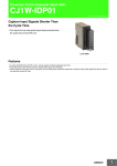
CJ1W-AD042
CJ1W-DA042V
Features
Analog Input Units
• Input up to eight analog signals with one Unit.
• Functions include line disconnection detection, averaging, peak value holding, offset/gain adjustment, and scaling.
(Offset/gain adjustment is not supported by the CJ1W-AD042. Scaling is supported only by the CJ1W-AD042.)
• High-speed A/D conversion in 20 μs/point with direct conversion function * (CJ1W-AD042 only).
Analog Output Units
• Output up to eight analog signals with one Unit.
• Functions include output holding, offset/gain adjustment, and scaling. (Offset/gain adjustment is not supported by the CJ1W-DA042V. Scaling
is supported only by the CJ1W-DA08V/DA08C/DA042V.)
• High-speed D/A conversion in 20 μs/point with direct conversion function * (CJ1W-DA042V only).
Analog I/O Units
• Input up to four analog signals and output up to two analog signals with one Unit.
• Functions include line disconnection detection, input averaging, scaling, input peak value holding, output holding, ratio conversion, and offset/
gain adjustment.
* Direct Conversion Instructions for High-speed Units can be used to create a consistent response time from input through data processing and
output.
System Configuration
Analog Input Unit
CPU Unit
Analog Output Unit
RUN
ERR/ALM
INH
PROGRAMMABLE
PRPHL
CONTROLLER
COMM
SYSMAC
CJ1G-CPU44
AD081-V1
RUN
ERC
ERH
ADJ
B1
DA041
RUN
ERC
ERH
ADJ
A1
B1
A1
OPEN
MCPWR
BUSY
MACH
MACH
No.
1
x10
No.
1
x10
x10
0
x10
0
PERIHERAL
1 2
1 2
MODE
MODE
PORT
Sensor
Temperature
Pressure
Speed
Flow rate
Regulator
(Temperature control)
Preamp
Servocontroller
M
(Position control)
Voltage
Current
Power
Power factor
Transducer
Variable speed
controller
M
(Speed control)
Chart recorder
Sensor
Note: The above diagram is an installation example for the CJ1W-AD081-V1 Analog Input Units and CJ1W-DA041 Analog Output Units.
1
CJ1W-AD/DA/MAD
Ordering Information
International Standards
• The standards are abbreviated as follows: U: UL, U1: UL (Class I Division 2 Products for Hazardous Locations), C: CSA, UC: cULus,
UC1: cULus (Class I Division 2 Products for Hazardous Locations), CU: cUL, N: NK, L: Lloyd, and CE: EC Directives.
• Contact your OMRON representative for further details and applicable conditions for these standards.
Analog Input Units
Unit type
Product
name
I/O
points
Signal
range
selection
Analog
Input
Unit
High-speed type
CJ1
Special
I/O Units
Analog
Input
Units
4
inputs
8
inputs
Set
separately
for each
input
Signal
range
Resolution
1 to 5 V (1/10,000),
0 to 10 V (1/20,000),
-5 to 5 V (1/20,000),
-10 to 10 V (1/40,000),
and
4 to 20 mA (1/10,000)
1 to 5 V,
0 to 5 V,
0 to 10 V,
-10 to 10 V,
4 to 20
mA
4
inputs
Conversion
Period
Accuracy at
ambient
temperature
of 25°C
Voltage:
±0.2% of
20 μs/1 point,
F.S.
25 μs/2 points,
30 μs/3 points,
Current:
35 μs/4 points
±0.4% of
F.S.
Current
No. of
consumption
unit
External
(A)
connection numbers
allocated 5 V 24 V
0.52
Removable
terminal
block
---
Model
CJ1W-AD042
Standards
UC1, CE
1
CJ1W-AD081-V1
1/4,000
(Settable
to
1/8,000)
*1
1 ms/point
(250 μs/point
can also be
set.)
*1
Voltage:
±0.2% of F.S.
Current:
±0.4% of F.S.
*2
0.42
UC1, N,
L, CE
--CJ1W-AD041-V1
*1 The resolution and conversion speed cannot be set independently. If the resolution is set to 1/4,000, then the conversion speed will be 1 ms/
point.
*2 At 23 ±2°C
Analog Output Units
Unit type
Product
name
I/O
points
Signal
range
selection
Signal
range
Resolution
Analog
Output
Unit
High-speed type
4
outputs
1 to 5 V (1/10,000),
0 to 10 V (1/20,000),
and
−10 to 10 V (1/40,000)
1 to 5 V,
0 to 5 V,
0 to 10 V, 1/4,000
Set
−10 to 10 V (Settable
separately
to
for each
1/8,000)
input
*1
8
4 to 20
outputs
mA
8
outputs
CJ1
Special
I/O Units
Analog
Input
Units
Accuracy at
No. of
External
Conversion
External
ambient
unit
power
Period
temperature connection
numbers
supply
of 25°C
allocated
20 μs/
1 point,
25 μs/
2 points,
30 μs/
3 points,
35 μs/
4 points
±0.3% of
F.S.
---
Current
consumption
(A)
5V
24 V
0.40
---
Model
Standards
UC1, CE
CJ1W-DA042V
24 VDC
+10%
−15%
1 ms/point
(Settable
±0.3% of
to 250 μs/
F.S.
point)
*1
,
140 mA
Removable max.
terminal
1
24 VDC
block
0.14
*2
CJ1W-DA08V
UC1, N,
L, CE
0.17
*2
CJ1W-DA08C
UC1, N,
CE
0.2
*2
CJ1W-DA041
0.14
+10%
−15%
,
170 mA
max.
24 VDC
4
outputs
2
outputs
1 to 5 V,
0 to 5 V,
0 to 10 V, 1/4,000
−10 to 10 V,
4 to 20 mA
1 ms/
point
Voltage:
±0.3% of
F.S.
Current:
±0.5% of
F.S.
+10%
−15%
,
200 mA
max.
24 VDC
+10%
−15%
,
140 mA
max.
UC1, N,
L, CE
0.12
0.14
*2
CJ1W-DA021
*1 The resolution and conversion speed cannot be set independently. If the resolution is set to 1/4,000, the conversion speed will be 1 ms/point.
*2 This is for an external power supply, and not for internal current consumption.
2
CJ1W-AD/DA/MAD
Analog I/O Units
Product
name
I/O
points
Analog
I/O
Units
4
inputs
Unit type
CJ1
Special
I/O Units
2
outputs
Signal
range
selection
Signal
range
1 to 5 V,
Set
0 to 5 V,
separately
0 to 10 V,
for each
−10 to 10 V,
input
4 to 20 mA
Accuracy at
Conversion
ambient
Resolution
Period
temperature
of 25°C
1/4,000
(Settable
to
1/8,000)
External
connection
Voltage:
±0.2% of F.S.
1 ms/
Current:
point
±0.2% of F.S. Removable
(Settable
terminal
to 500 μs/ Voltage:
block
±0.3% of F.S.
point)
Current:
±0.3% of F.S.
Current
No. of
consumption
unit
(A)
numbers
allocated 5 V
24 V
1
0.58
−
Model
Standards
CJ1W-MAD42
UC1, N,
L, CE
Note: The resolution and conversion speed cannot be set independently. If the resolution is set to 1/4,000, then the conversion speed will be 1
ms/point.
Accessories
Model
Accessories
CJ1W-AD081-V1/AD041-V1
CJ1W-DA08V/DA08C/DA041/DA021
CJ1W-DA042V
CJ1W-MAD42
None.
CJ1W-AD042
Four jumpers
(For a current input, a jumper is used to connect the current input positive terminal and the voltage input positive terminal.)
Mountable Racks
Model
CJ1W-AD042
CJ system (CJ1, CJ2)
CPU Rack
Expansion Backplane
8 Units *1
9 Units *2
(per Expansion
Backplane)
10 Units *1
10 Units *2
(per Expansion
Backplane)
7 Units *1
8 Units *2
(per Expansion
Backplane)
CP1H system
CP1H PLC
NSJ system
NSJ Controller
Expansion Backplane
9 Units *2
(per Expansion
Backplane)
CJ1W-AD081-V1
CJ1W-AD041-V1
CJ1W-DA042V
CJ1W-DA08V
CJ1W-DA08C
2 Units *3
Not supported
10 Units *2
(per Expansion
Backplane)
CJ1W-DA041
CJ1W-DA021
CJ1W-MAD42
8 Units *2
(per Expansion
Backplane)
Note: It may not be possible to mount this many Units to a Rack depending on the current consumption of the other Units.
*1 This is the number of Units for a CJ2H-CPU6@ CJ2H CPU Unit (without EtherNet/IP) and a CJ1W-PA205@ or CJ1W-PD025 Power Supply Unit.
*2 This is the number of Units for a CJ1W-PA205@ or CJ1W-PD025 Power Supply Unit.
*3 A CP1W-EXT01 CJ Unit Adaptor is required.
3
CJ1W-AD/DA/MAD
Individual Specifications
Analog Input Units CJ1W-AD041-V1/AD081-V1/AD042
Specifications
Item
CJ1W-AD041-V1
CJ1W-AD081-V1
Unit type
CJ-series Special I/O Unit
Isolation *1
Between I/O and PLC signals: Photocoupler
(No isolation between I/O signals.)
External terminals
18-point detachable terminal block (M3 screws)
Power consumption
420 mA max. at 5 VDC
Dimensions (mm)
31 × 90 × 65 mm (W × H × D)
Weight
140 g max.
General specifications
Conforms to general specifications for SYSMAC CJ Series.
Number of analog inputs
4
Input signal range *2
1 to 5 V
0 to 5 V
0 to 10 V
−10 to 10 V
4 to 20 mA
*3
Maximum rated input
(for 1 point) *5
Voltage Input: ±15 V
Current Input: ±30 mA
Input impedance
Voltage Input: 1 MΩ min.
150 g max.
8
Accuracy *7
Current Input: 250 Ω (rated value)
1 to 5 V
10,000
0 to 10 V
20,000
−5 to 5 V
20,000
−10 to 10 V
40,000
4 to 20 mA
10,000
16-bit binary data
25°C *8
Voltage Input: ±0.2% of F.S.Current Input: ±0.4% of F.S.
0°C to 55°C
Voltage Input: ±0.4% of F.S.Current Input: ±0.6% of F.S.
A/D conversion period *9
1 ms/250 μs *6
20 μs/1 point, 25 μs/2 points,
30 μs/3 points, 35 μs/4 points
Mean value processing
Stores the last "n" data conversions in the buffer, and stores the mean value
of the conversion values.
Buffer number: n = 2, 4, 8, 16, 32, 64
Stores the last "n" data conversions
in the buffer, and stores the mean
value of the conversion values.
Buffer number:
n = 2, 4, 8, 16, 32, 64, 128, 256, 512
Peak value holding
Stores the maximum conversion value while the Peak Value Hold Bit is ON.
Scaling
Input
functions
4
1 to 5 V
0 to 10 V
−5 to 5 V
−10 to 10 V
4 to 20 mA
*4
4,000/8,000 *6
Converted output data
Between I/O and PLC signals:
Digital isolator (No isolation between
I/O signals.)
520 mA max. at 5 VDC
Input
specifications
Resolution
CJ1W-AD042
---
Setting values in any specified unit
within a range of ±32,000 as the upper
and lower limits allows A/D conversion to
be executed and analog signals to be
output with these values as full scale.
Input disconnection detection
Detects the disconnection and turns ON the Disconnection Detection Flag. *10
Offset/gain adjustment
Supported
Direct conversion
---
---
A/D conversion is performed and the
converted value is refreshed when the
ANALOG INPUT DIRECT CONVERSION instruction (AIDC) is executed.
This instruction is supported by the
CJ2@-CPU@@(-EIP) CPU Units with
unit version 1.1 or later.
CJ1 and CP1H CPU Units and NSJ
Controllers do not support direct conversion.
*1 Do not apply a voltage higher than 600 V to the terminal block when performing withstand voltage test on this Unit. Otherwise, internal elements
may deteriorate.
*2 Input signal ranges can be set for each input.
*3 Voltage input or current input are chosen by using the voltage/current switch at the back of the terminal block.
*4 To use a current input, connect the positive current input terminal and positive voltage input terminal with the enclosed short bar.
*5 The Analog Input Unit must be operated according to the input specifications provided here. Operating the Unit outside these specifications
will cause the Unit to malfunction.
*6 The resolution can be set to 8,000 and the conversion period to 250 μs in the DM Area (m+18). There is only one setting for both of these, i.e.,
they are both enabled or disabled together.
*7 The accuracy is given for full scale. For example, an accuracy of ±0.2% means a maximum error of ±8 (BCD) at a resolution of 4,000.
For the CJ1W-AD041-V1/ AD081-V1, the default setting is adjusted for voltage input. To use current input, perform the offset and gain
adjustments as required.
*8 For the CJ1W-AD041-V1/ AD081-V1, 23±2°C.
*9 The A/D conversion period is the time required from when the Analog Input Unit receives the analog signal until it stores the converted value
in internal memory. It takes at least one cycle for the converted data to be stored in the CPU Unit. (The direct conversion function of the CJ1WAD042 is can be used to input data immediately to the CPU Unit.)
*10 Line disconnection detection is supported only when the range is set to 1 to 5 V or 4 to 20 mA. If there is no input signal when the 1 to 5 V or
4 to 20 mA range is set, the Line Disconnection Flag will turn ON.
4
CJ1W-AD/DA/MAD
Analog Output Units CJ1W-DA021/DA041/DA08V/DA08C/DA042V
Specifications
Item
CJ1W-DA021
CJ1W-DA041
CJ1W-DA08V
CJ1W-DA08C
Unit type
CJ-series Special I/O Unit
Isolation *1
Between I/O and PLC signals: Photocoupler (No isolation between I/O signals.)
External terminals
18-point detachable terminal block (M3 screws)
Power consumption
5 VDC, 120 mA max.
5 VDC, 140 mA max.
CJ1W-DA042V
Between outputs and PLC signals:
Digital isolator (No isolation between
output signals.)
5 VDC, 400 mA max.
+10%
24 VDC −15% (inrush current: 20 A min., pulse width: 1 ms min)
External power supply *2
140 mA max.
200 mA max.
Dimensions (mm)
31 × 90 × 65 mm (W × H × D)
Weight
150 g max.
General specifications
---
8
8
4
Output signal range *3
1 to 5 V/4 to 20 mA
0 to 5 V
0 to 10 V
−10 to 10 V
1 to 5 V
0 to 5 V
0 to 10 V
−10 to 10 V
4 to 20 mA
1 to 5 V
0 to 10 V
−10 to 10 V
Output impedance
0.5 Ω max. (for voltage output) XXXX
0.5 Ω max.
(for voltage output)
---
0.5 Ω max.
(for voltage output)
Max. output current (for 1
point)
12 mA (for voltage output) XXXX
2.4 mA
(for voltage output)
---
2 mA
(for voltage output)
Maximum permissible
load resistance
600 Ω (current output)
Resolution
4,000
Set data
4
---
350 Ω
4,000/8,000 *8
--1 to 5 V
10,000
0 to 10 V
20,000
-10 to 10 V
40,000
16-bit binary data
25°C
Voltage output: ±0.3% of F.S.
Current output: ±0.5% of F.S.
±0.3% of F.S.
±0.3% of F.S.
±0.3% of F.S.
0°C to 55°C
Voltage output: ±0.5% of F.S.
Current output: ±0.8% of F.S.
±0.5% of F.S.
±0.6% of F.S.
±0.5% of F.S.
D/A conversion period *5
1.0 ms per point
1.0 ms or 250 μs per point *8
Output hold function
Outputs the specified output status (CLR, HOLD, or MAX) under any of the following circumstances.
• When the Conversion Enable Bit is OFF. *6
• In adjustment mode, when a value other than the output number is output during adjustment. *7
• When output setting value error occurs or PLC operation stops.
• When the CPU Unit is on standby.
• When the Load is OFF.
Accuracy
*4
Scaling
Output
functions
--170 mA max.
Conforms to general specifications for SYSMAC CJ-series Series.
Number of analog outputs 2
Output
specifications
140 mA max.
---
Offset/gain adjustment
Supported only for a conversion period of
1 ms and resolution of 4,000.
Setting values in any specified unit within a
range of ±32,000 as the upper and lower
limits allows D/A conversion to be executed and analog signals to be output with
these values as full scale.
Supported
Direct conversion
20 μs/1 point,
25 μs/2 points,
30 μs/3 points,
35 μs/4 points
Setting values in any specified
unit within a range of ±32,000
as the upper and lower limits
allows D/A conversion to be
executed and analog signals to
be output with these values as
full scale.
---
---
D/A conversion is performed and
the output value is refreshed
when the ANALOG OUTPUT DIRECT CONVERSION instruction
(AODC) is executed. This instruction is supported by the CJ2@CPU@@(-EIP) CPU Units with
unit version 1.1 or later.
CJ1 and CP1H CPU Units and
NSJ Controllers do not support
direct conversion.
*1 Do not apply a voltage higher than 600 V to the terminal block when performing withstand voltage test on this Unit.
*2 The maximum number of Analog Output Units that can be mounted to one Rack varies depending on the current consumption of the other
Units mounted to the Rack.
Select a 24 VDC power supply based on the surge current. The following OMRON external power supplies are recommended.
Manufacturer
OMRON
Model number
Specifications
S8VS-06024
100 to 240 VAC, 60 W
S8VS-12024
100 to 240 VAC, 120 W
S8VM-05024
100 to 240 VAC, 50 W
S8VM-10024
100 to 240 VAC, 100 W
*3 Output signal ranges can be set for each output.
5
CJ1W-AD/DA/MAD
*4 The accuracy is given for full scale. For example, an accuracy of ±0.3% means a maximum error of ±60 mV for a −10 to 10 V range. For the
CJ1W-DA021/041, the accuracy is at the factory setting for a current output. When using a voltage output, adjust the offset gain as required.
*5 The D/A conversion period is the time required for the Analog Output Unit to convert and output the data that was received from the CPU Unit.
It takes at least one cycle for the data stored in the CPU Unit to be read by the Analog Output Unit. (The direct conversion function of the CJ1WDA042V can be used to output data immediately from the CPU Unit.)
*6 When the operation mode for the CPU Unit is changed from RUN mode or MONITOR mode to PROGRAM mode, or when the power is turned
ON, the Output Conversion Enable Bit will turn OFF. The output status specified according to the output hold function will be output.
*7 The CJ1W-DA042V does not have an Adjustment Mode.
*8 The CJ1W-DA08V/08C can be set to a conversion cycle of 250 μs and a resolution of 8,000 using the setting in D (m+18).
Analog I/O Unit CJ1W-MAD42
Specifications
Item
CJ1W-MAD42
Unit type
CJ-series Special I/O Unit
Isolation
Between I/O and PLC signals: Photocoupler
(No isolation between I/O signals.)
External terminals
18-point detachable terminal block (M3 screws)
Current consumption
580 mA max. at 5 V DC
Dimensions (mm)
31 × 90 × 65 mm (W × H × D)
Weight
150 g max.
General specifications
Conforms to general specifications for SYSMAC CJ-series Series.
Input Specifications and Functions
Item
Voltage input
Current input
Number of analog inputs
4
Input signal range *1
1 to 5 V
0 to 5 V
0 to 10 V
−10 to 10 V
4 to 20 mA *2
Maximum rated input (for 1
point) *3
±15 V
±30 mA
Input impedance
1 MΩ min.
250 Ω (rated value)
Resolution
4,000/8,000 *7
Converted output data
Accuracy *4
16-bit binary data
25°C
±0.2% of F.S.
0°C to 55°C
±0.4% of F.S.
A/D conversion period *5
1.0 ms/500 μs per point *7
Mean value processing
Stores the last "n" data conversions in the buffer, and stores the mean value of the conversion values.
Buffer number: n = 2, 4, 8, 16, 32, 64
Peak value holding
Stores the maximum conversion value while the Peak Value Hold Bit is ON.
Scaling
Enabled only for conversion period of 1 ms and resolution of 4,000. Setting any values within a range of
±32,000 as the upper and lower limits allows the A/D conversion result to be output with these values as full
scale.
Input disconnection detection Detects the disconnection and turns ON the Disconnection Detection Flag.
Offset/gain adjustment
Supported
6
CJ1W-AD/DA/MAD
Output Specifications
Item
Voltage output
Current output
Number of analog outputs
2
Output signal range *1
1 to 5 V
0 to 5 V
0 to 10 V
−10 to 10 V
4 to 20 mA
Output impedance
0.5 Ω max.
−
Maximum external output
current (for 1 point)
2.4 mA
−
Maximum allowed load
resistance
−
600 Ω
Resolution
4,000/8,000 *7
Set data
Accuracy *4
16-bit binary data
25°C
±0.3% of F.S.
±0.3% of F.S.
0°C to 55°C
±0.5% of F.S.
±0.6% of F.S.
D/A conversion period *5
1.0 ms/500 μs per point
Output hold function
Outputs the specified output status (CLR, HOLD, or MAX) under any of the following circumstances.
• When the Conversion Enable Bit is OFF. *6
• In adjustment mode, when a value other than the output number is output during adjustment.
• When output setting value error occurs or PLC operation stops.
• When the CPU Unit is on standby.
• When the Load is OFF.
Scaling
Enabled only for conversion period or 1 ms and resolution of 4,000. Setting any values within a range of
±32,000 as the upper and lower limits allows D/A conversion to be executed and analog signals to be output
with these values as full scale.
Ratio conversion function *5
Stores the results of positive and negative gradient analog inputs calculated for ratio and bias as analog output
values.
Positive gradient: Analog output = A × Analog input + B
(A: 0 to 99.99, B: 8000 to 7FFF hex)
Negative gradient:Analog output = F − A × Analog input + B
(A: 0 to 99.99, B: 8000 to 7FFF hex, F: Output range maximum value)
Offset/gain adjustment
Supported
*1 Input and output signal ranges can be set for each input and output.
*2 Voltage input or current input are chosen by using the voltage/current switch at the back of the terminal block.
*3 The Analog I/O Unit must be operated according to the input specifications provided here. Operating the Unit outside these specifications will
cause the Unit to malfunction.
*4 The accuracy is given for full scale. For example, for an input, an accuracy of ±0.2% means a maximum error of ±8 (BCD) at a resolution of
4,000. For an output, an accuracy of ±0.3% means a maximum error of ±60 mV for a −10 to 10 V range.
*5 The A/D conversion period is the time required from when the Analog Input Unit receives the analog signal until it stores the converted value
in internal memory. It takes at least one cycle for the converted data to be stored in the CPU Unit.
The D/A conversion period is the time required for the Analog Output Unit to convert and output the data that was received from the CPU Unit.
It takes at least one cycle for the data stored in the CPU Unit to be read by the Analog Output Unit.
*6 When the operation mode for the CPU Unit is changed from RUN mode or MONITOR mode to PROGRAM mode, or when the power is turned
ON, the Output Conversion Enable Bit will turn OFF. The output status specified according to the output hold function will be output.
*7 By means of the D (m+18) setting, the resolution can be changed to 8,000, and the conversion period can be changed to 500 μs.
7
CJ1W-AD/DA/MAD
External Interface
Analog Input Units CJ1W-AD041-V1/AD081-V1/AD042
Components
Front
With Terminal Block
With Terminal Block Removed
Indicators *1
MACH
x10 1
Terminal block
B1
A1
78
456
456
x10 0
Voltage/current
switch *2
23
ON
1
2
ON
1
2
23
901
x10 0
78
901
78
ON
1
No.
456
78
456
x10 1
901
No.
RUN
ERC
ERH
ADJ
A1
23
MACH
B1
901
Unit number
setting switch
AD081-V1
23
RUN
ERC
ERH
ADJ
2
AD081-V1
O
N
O
N
ON
MODE
1
2
1 2
1 2
MODE
Terminal block
DIN Track
mounting pin
Operating mode switch *2
Side
Terminal block lock lever
(pull down to release terminal block)
Slider
Expansion connector
*1 The ADJ LED is not provided with the CJ1W-AD042.
*2 This switch is not mounted for the CJ1W-AD042.
Slider
Indicators
The indicators show the operating status of the Unit. The following table shows the meanings of the indicators.
LED
Meaning
RUN (green)
Operating
ERC (red)
Error detected by Unit
Indicator
Lit
Not lit
Lit
Not lit
ERH (red)
ADJ (yellow) *
Error in the CPU Unit
Adjusting
Lit
Not lit
Flashing
Not lit
Operating status
Operating in normal mode.
Unit has stopped exchanging data with the CPU Unit.
Alarm has occurred (such as disconnection detection) or initial
settings are incorrect.
Operating normally.
Error has occurred during data exchange with the CPU Unit.
Operating normally.
Operating in offset/gain adjustment mode.
Other than the above.
* The ADJ LED is not provided with the CJ1W-AD042.
8
CJ1W-AD/DA/MAD
Input Circuits
The following diagrams show the internal circuit of the analog input section.
CJ1W-AD041-V1/AD081-V1
15 kΩ
Input (+)
CJ1W-AD042
15 kΩ
250 Ω
1 MΩ
15 kΩ
15 kΩ
Input (–)
AG
(analog 0 V)
Input circuit
and
conversion
circuit
Voltage/
current
input switch
Current
Input (+)
250 Ω
Voltage
Input (+)
2.2 kΩ
Input circuit
and
conversion
circuit
510 kΩ
2.2 kΩ
Input (–)
1 MΩ
AG (common to all inputs)
510 kΩ
AG
(analog 0 V)
AG (common to all inputs)
Terminal Arrangement
The signal names corresponding to the connecting terminals are as shown in the following diagram.
CJ1W-AD041-V1
Input 2 (+)
CJ1W-AD081-V1
B1
A1
Input 2 (−)
B2
Input 4 (+)
B3
Input 4 (−)
B4
AG
B5
N.C.
B6
N.C.
B7
N.C.
B8
N.C.
B9
A2
A3
A4
A5
A6
A7
A8
Input 2 (+)
B1
Input 2 (−)
B2
Input 4 (+)
B3
Input 4 (−)
B4
AG
B5
Input 6 (+)
B6
Input 6 (−)
B7
Input 8 (+)
B8
Input 8 (−)
B9
Input 1 (+)
Input 1 (−)
Input 3 (+)
Input 3 (−)
AG
N.C.
N.C.
N.C.
A9
N.C.
A1
Current Input 1 (+)
A2
Voltage Input 1 (+)
A3
Input 1 (−)
A4
AG
A5
Current Input 3 (+)
A6
Voltage Input 3 (+)
A7
Input 3 (−)
A8
AG
A9
N.C.
A1
Input 1 (+)
A2
Input 1 (−)
A3
Input 3 (+)
A4
Input 3 (−)
A5
AG
A6
Input 5 (+)
A7
Input 5 (−)
A8
Input 7 (+)
A9
Input 7 (−)
CJ1W-AD042
Current Input 2 (+)
B1
Voltage Input 2 (+)
B2
Input 2 (−)
B3
AG
B4
Current Input 4 (+)
B5
Voltage Input 4 (+)
B6
Input 4 (−)
B7
AG
B8
N.C.
B9
Note: 1.
2.
3.
4.
5.
The analog input numbers that can be used are set in the Data Memory (DM).
The input signal ranges for each input are set in the Data Memory (DM). They can be set in units of input numbers.
The AG terminals are connected to the 0 V analog circuit in the Unit. Connecting shielded input lines can improve noise resistance.
Do not connect anything to NC terminals.
To use a current input with the CJ1W-AD042, connect the positive current input terminal and positive voltage input terminal with the
enclosed short bar.
6. Connect a surge suppressor to inductive loads in the system (e.g., magnetic contactors, relays, and solenoids).
9
CJ1W-AD/DA/MAD
Analog Output Units CJ1W-DA021/041/08V/08C/DA042V
Components
Side
Front
Slider
With Terminal Block
Indicators *1
DA041
RUN
ERC
ERH
ADJ
78
23
No.
456
MACH
x10 1
A1
901
Unit number
switches
B1
901
456
78
23
x10 0
O
N
Expansion
connector
1 2
MODE
Terminal block
Terminal block lock lever
(pull down to release terminal block)
Slider
Operating mode switch
*2
DIN Track mounting pin
*1 The ADJ LED is not provided with the CJ1W-DA042V.
*2 This switch is not mounted for the CJ1W-DA08V, CJ1W-DA08C and CJ1W-DA042V.
Indicators
The indicators show the operating status of the Unit. The following table shows the meanings of the indicators.
LED
RUN (green)
ERC (red)
Meaning
Operating
Error detected by Unit
Indicator
Lit
Not lit
Lit
Not lit
ERH (red)
ADJ (yellow) *
Error in the CPU Unit
Adjusting
Lit
Not lit
Flashing
Not lit
Operating status
Operating in normal mode.
Unit has stopped exchanging data with the CPU Unit.
Alarm has occurred (such as disconnection detection) or initial
settings are incorrect.
Operating normally.
Error has occurred during data exchange with the CPU Unit.
Operating normally.
Operating in offset/gain adjustment mode.
Other than the above.
* The ADJ LED is not provided with the CJ1W-DA042V.
10
CJ1W-AD/DA/MAD
Output Circuits
The following diagrams show the internal circuit of the analog output section.
CJ1W-DA021/DA041/DA08V/DA08C
Voltage Output Circuits
Current Output Circuits
Current output section
Voltage output section
Output
switch and
conversion
circuit
AMP
Voltage
output (+)
Voltage
output (–)
Output
switch and
conversion
circuit
Current
output (+)
AMP
AMP
Current
output (−)
AG (common to all outputs)
CJ1W-DA042V
Voltage Output Circuits
Output
switch and
conversion
circuit
AMP
Voltage
output (+)
Voltage
output (–)
AG (common to all outputs)
Terminal Arrangement
The signal names corresponding to the connecting terminals are as shown in the following diagram.
CJ1W-DA021
Voltage output 2 (+)
CJ1W-DA041
B1
A1
Output 2 (−)
B2
Current output 2 (+)
B3
N.C.
B4
N.C.
B5
N.C.
B6
A2
A3
A4
N.C.
B7
N.C.
B8
0V
B9
N.C.
Output 2 (−)
B2
Output 4 (+)
B3
Output 4 (−)
B4
A2
Output 6 (+)
B5
Output 6 (−)
B6
Output 8 (+)
B7
Output 8 (−)
B8
0V
B9
Output 4 (−)
B5
Current output 4 (+)
B6
N.C.
B7
N.C.
B8
0V
B9
Output 3 (−)
Output 2 (+)
B1
Output 2 (−)
B2
N.C.
B3
Output 4 (+)
B4
Output 4 (−)
B5
N.C.
B6
N.C.
B7
N.C.
B8
N.C.
B9
Output 5 (+)
Output 5 (−)
Output 7 (+)
A8
Output 7 (−)
A9
24 V
A1
Voltage output 1 (+)
A2
Output 1 (−)
A3
Current output 1 (+)
A4
Voltage output 3 (+)
A5
Output 3 (−)
A6
Current output 3 (+)
A7
N.C.
A8
N.C.
A9
24 V
A1
Output 1 (+)
A2
Output 1 (−)
A3
N.C.
A4
Output 3 (+)
A5
Output 3 (−)
A6
N.C.
A7
N.C.
A8
N.C.
A9
N.C.
CJ1W-DA042V
Output 1 (−)
Output 3 (+)
A7
B4
Output 1 (+)
A4
A6
Voltage output 4 (+)
24 V
A3
A5
B3
N.C.
B1
A1
Current output 2 (+)
N.C.
CJ1W-DA08V (Voltage Output)
and CJ1W-DA08C (Current Output)
Output 2 (+)
B2
N.C.
N.C.
A9
Output 2 (−)
Current output 1 (+)
A6
A8
B1
Output 1 (−)
A5
A7
Voltage output 2 (+)
Voltage output 1 (+)
Note: 1.
2.
3.
4.
The analog output numbers that can be used are set in the Data Memory (DM).
The output signal ranges for each output are set in the Data Memory (DM). They can be set in units of output numbers.
The N.C. terminals are not connected to internal circuit.
Use a separate power supply from the one used for Basic I/O Units. Faulty Unit operation may be caused by noise if power is supplied
from the same source. (This does not apply to CJ1W-DA042V.)
5. Connect a surge suppressor to inductive loads in the system (e.g., magnetic contactors, relays, and solenoids).
11
CJ1W-AD/DA/MAD
Analog I/O Unit CJ1W-MAD42
Components
Front
With Terminal Block Removed
With Terminal Block
Indicators
MAD42
MAD42
RUN
ERC
ERH
ADJ
No.
456
23
Voltage/current
switch
ON
1
2
ON
1
2
23
x10 0
901
78
901
456
78
x10 0
A1
78
456
23
456
MACH
x10 1
Terminal block
B1
901
78
901
No.
x10 1
RUN
ERC
ERH
ADJ
A1
23
MACH
User
number
setting
switch
B1
Terminal block
DIN Track
mounting pin
Terminal block lock lever
(pull down to release terminal bloc
Side
Slider
Expansion connector
Slider
Indicators
The indicators show the operating status of the Unit. The following table shows the meanings of the indicators.
LED
Meaning
RUN (green)
Operating
ERC (red)
Error detected by Unit
Indicator
Lit
Not lit
Lit
Not lit
ADJ (yellow)
ERH (red)
Adjusting
Error in the CPU Unit
Flashing
Not lit
Lit
Not lit
Operating status
Operating in normal mode.
Unit has stopped exchanging data with the CPU Unit.
Alarm has occurred (such as disconnection detection) or initial
settings are incorrect.
Operating normally.
Operating in offset/gain adjustment mode.
Other than the above.
Error has occurred during data exchange with the CPU Unit.
Operating normally.
12
CJ1W-AD/DA/MAD
I/O Circuit
The following diagrams show the internal circuit of the analog I/O section.
Input Circuits
15 kΩ
Input (+)
15 kΩ
250 Ω
1 MΩ
15 kΩ
15 kΩ
Input (–)
Voltage/
current
input switch
AG
(analog 0 V)
Input circuit
and
conversion
circuit
1 MΩ
AG (common to all inputs)
Voltage Output Circuits
Output
switch and
conversion
circuit
Current Output Circuits
AMP
Voltage
output (+)
Voltage
output (–)
AG (common to all outputs)
Output
switch and
conversion
circuit
AMP
AMP
Current
output (+)
Current
output (–)
Terminal Arrangement
The signal names corresponding to the connecting terminals are as shown in the following diagram.
CJ1W-MAD42
Voltage output 2 (+)
B1
Output 2 (–)
B2
Current output 2 (+)
B3
N.C.
B4
Input 2 (+)
B5
Input 2 (–)
B6
AG
B7
Input 4 (+)
B8
Input 4 (–)
B9
Note: 1.
2.
3.
4.
A1
Voltage output 1 (+)
A2
Output 1 (–)
A3
Current output 1 (+)
A4
N.C.
A5
Input 1 (+)
A6
Input 1 (–)
A7
AG
A8
Input 3 (+)
A9
Input 3 (–)
The analog I/O numbers that can be used are set in the Data Memory (DM).
The I/O signal ranges for each input and output are set in the Data Memory (DM). They can be set in units of I/O numbers.
The AG terminal (A7, B7) is connected to the 0 V analog circuit in the Unit. Connecting shielded input lines can improve noise resistance.
The N.C. terminals (A4, B4) are not connected to internal circuit.
Wiring Vasic I/O Units with Terminal Blocks
Crimp terminals
Use crimp terminals (M3) having the dimensions shown below.
6.2 mm max.
6.2 mm max.
13
CJ1W-AD/DA/MAD
Dimensions
(Unit: mm)
CJ1W-AD041-V1/081-V1/AD042
CJ1W-DA021/041/08V/08C/DA042V
CJ1W-MAD42
Terminal Block
Dimensions
89
31
65
2.7
17.5
8.2
AD081-V1
RUN
ERC
ERH
ADJ
B1
A1
6.4
456
78
901
No.
7.62
23
MACH
x10 1
901
23
x10 0
456
78
90
74.77
O
N
1 2
MODE
2.7
Note: The appearance varies with the model.
About Manuals
Cat. No
Model
Manual name
Contents
W345
SYSMAC CS/CJ Series
CS1W-AD041-V1/081-V1/161
CS1W-DA041/08V/08C
CS1W-MAD44
CJ1W-AD041-V1/081-V1
CJ1W-DA021/041/08V/08C
CJ1W-MAD42
CS/CJ-series
Analog I/O Units
Operation Manual
Provides information on using the CS/CJ-series Analog Input,
Analog Output, and Analog I/O Units.
W393
CJ1H-CPU@@H-R
CJ1G/H-CPU@@H
CJ1G-CPU@@P
CJ1G-CPU@@
CJ1M-CPU@@
SYSMAC CJ Series
Programmable Controllers
Operation Manual
Provides an outlines of and describes the design, installation,
maintenance, and other
basic operations for the CJ-series PLCs.
Describes the following for CJ2 CPU Units:
• Overview and features
• Basic system configuration
• Part nomenclature and functions
• Mounting and setting procedure
• Remedies for errors
Also refer to the Software User's Manual (W473).
W472
CJ2H-CPU6@-EIP
CJ2H-CPU6@
CJ-series
CJ2 CPU Unit
Hardware User's Manual
W474
CJ2H-CPU6@-EIP
CJ2H-CPU6@
CS1G/H-CPU@@H
CS1G/H-CPU@@-V1
CJ1G/H-CPU@@H
CJ1G-CPU@@
CJ1M-CPU@@
NSJ@-@@@@(B)-G5D
NSJ@-@@@@(B)-M3D
CS/CJ/NSJ-series
Describes each programming instruction in detail.
Instructions Reference Manual
14