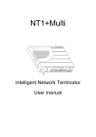
1
RELAYDRIVER TM Logic Module Accessory Installation and Operation Manual ….. Four Channel Relay Driver ….. 1098 Washington Crossing Road Washington Crossing, PA 18977 USA phone: 215.321.4457 fax: 215.321.4458 email: [email protected] www.morningstarcorp.com Table of Contents 1.0 Getting Started...........................................................3 1.1 What’s in the Box?..................................................................... 3 1.2 Features..................................................................................... 4 1.3 Factory Settings......................................................................... 5 2.0 PC Software Installation ...........................................6 2.1 System Requirements ............................................................... 6 2.2 Installing MSView.................................................................. 6 3.0 Configuration .............................................................9 3.1 Open the Setup Wizard ............................................................. 9 3.2 Assign Functions ..................................................................... 10 3.3 Programming the Relay Driver ................................................ 34 4.0 Mounting...................................................................40 4.1 Required Tools ........................................................................ 40 4.2 Wall Mounting .......................................................................... 41 4.3 DIN Rail Mounting.................................................................... 43 5.0 Wiring........................................................................45 5.1 Channel Wiring ........................................................................ 45 5.2 Communications Wiring........................................................... 50 6.0 Operation..................................................................53 6.1 LED Indications........................................................................ 53 6.2 Protections............................................................................... 55 6.3 Maintenance ............................................................................ 55 7.0 Troubleshooting FAQs............................................56 Appendix A – MS Product Variables ...........................59 Warranty .........................................................................61 Technical Specifications...............................................62 1 MORNINGSTAR CORPORATION IMPORTANT SAFETY INSTRUCTIONS SAVE THESE INSTRUCTIONS: This manual contains important safety, installation and operating instructions for the Morningstar Relay Driver. The following symbols are used throughout this manual to indicate potentially dangerous conditions or important safety instructions. WARNING: Indicates a potentially dangerous ondition. Use extreme caution when performing this task. CAUTION: Indicates a critical procedure for safe and proper operation of the Relay Driver. NOTE: Indicates a procedure or function that is important to the safe and proper operation of the Relay Driver. General Safety Information Read all the instructions and cautions in the manual before starting the installation. There are no user serviceable parts in the Relay Driver. Do not disassemble or attempt to repair. Ensure that battery power has been disconnected before installing or removing the Relay Driver. Do not allow water to enter the Relay Driver. RELAY DRIVER 2 1.0 Getting Started 1.1 What’s in the Box? Relay Driver Software CD Operator’s Manual Serial RS-232 Cable (6ft) Meter Bus RJ-11 cable (4ft) Four (4) Mounting Screws Mounting Template 3 MORNINGSTAR CORPORATION 1.2 Features Figure 1. Features of the Relay Driver Channel Terminal Block Provides connections for: Relay Driver power and ground Four (4) Channel connections (relay contacts, input voltages, output signals, etc) DIN Rail Release Tab Snap on / Release from DIN rail. LED Indicators Displays power and channel status, faults, sampling interval. Meter Bus Ports Connects to other Morningstar products with meter bus communications. Two ports (in/out) allow a daisy-chain connection of multiple devices. Serial RS-232 Port A serial programming port used to establish a connection between the Relay Driver and a PC. RELAY DRIVER 4 1.3 Factory Settings The Relay Driver is pre-configured at the factory with a default configuration as outlined below. If a different configuration is needed, a custom configuration will need to be programmed into the Relay Driver. Sections 2.0 through 5.0 explain software installation, custom configuration, and installation. Channel 1 Threshold Function: Channel OFF when Vbattery < 11.5V Channel ON when Vbattery > 12.6V 1 minute delay before turning on/off Channel 2 Threshold Function: Channel OFF when Vbattery < 11.1V Channel ON when Vbattery > 12.2V 1 minute delay before turning on/off Channel 3 Threshold Function: Channel OFF when Vbattery < 14.0V Channel ON when Vbattery > 15.0V Channel 4 TriStar Alarm/Fault Monitor: Channel OFF when no alarms/faults exist Channel ON when any alarms/faults exist Excludes RTS open alarm No communication timeout alarm 5 MORNINGSTAR CORPORATION 2.0 PC Software Installation 2.1 System Requirements NOTE: Morningstar provides software for Windows® PCs only. Other platforms are not supported. • • • • • • • Intel® 486 or Pentium® processor Microsoft® Windows 95, 98, 2000, Windows XP Professional or Home Edition 32MB of RAM (64MB Recommended) CD-ROM drive (If installing by CD) Up to 1.5MB of available hard-disk space Internet connection and service (If downloading from web) Web browser (If downloading from web) 2.2 Installing MSView NOTE: The software CD provided may not contain the latest version of MSView. Check our website for updates at: http://www.morningstarcorp.com/products/software Morningstar MSView is an all-inclusive software package that provides programming, graphing, and logging capabilities for supported Morningstar products. MSView is also used to configure and program the Relay Driver. RELAY DRIVER 6 This section details two software installation options. The first option explains how to install MSView from the included software CD. The second option explains how to download and install the latest version of MSView from our website. We recommend downloading the latest version from our website if possible. It is possible to update to a newer version of MSView at a later time. Option #1: Install MSView from the included CD Step 1 Insert the MSView Setup CD in the PC CD-drive. After a few moments, the MSView software setup wizard should appear. If setup does not begin (or the autorun CD-drive feature has been disabled), run Setup.exe on the CD drive using Windows Explorer. Step 2 Follow the wizard instructions to install MSView software. Step 3 After the install is complete, remove the CD from the drive and store the MSView setup CD in a safe place. - OR Option #2: Download and install MSView software from the web Step 1 Visit: http://www.morningstarcorp.com/products/software 7 MORNINGSTAR CORPORATION Follow the page instructions to download the latest version of MSView. Save the file to a convenient location such as the Windows Desktop. Step 2 Find the saved file downloaded in step 1. Run the setup file and follow the wizard instructions. Step 3 After the install is complete, you can delete the setup file or save it in a safe place on your hard drive for future use. NOTE: If an older version of MSView is already installed, the setup program will automatically replace the older version. RELAY DRIVER 8 3.0 Configuration The MSView software includes a Relay Driver setup wizard to create and save configurations. Configurations can then be programmed into the Relay Driver so that it functions as required. 3.1 Open the Setup Wizard 1. Click the Windows Start Menu button 2. Under Programs, find the MSView Folder. 3. Click the Relay Driver Wizard program Icon Figure 2. Relay Driver Setup Screen 9 The Relay Driver Setup screen should appear (see Fig. 2). The setup wizard is now open. Proceed to section 3.2. MORNINGSTAR CORPORATION 3.2 Assign Functions Each of the four channels is assigned a Function, which switches channel(s) on/off based on criteria. Some Functions only control one channel while others manage two or more channels as a group. The Relay Driver Setup screen, shown in Figure 3 is the starting point from which each channel is setup. The upper left area of the window displays the four channels and the corresponding configurations. Each of the four (4) channels has a configuration summary that shows which Function is assigned as well as a few key parameters. Next to each channel Configuration Summary are two setup buttons labeled Simple and Advanced. Simple setup allows the user to modify the most essential settings while using factory default values for the more advanced settings. Advanced setup allows the user to specify all parameters including control address, sample rate, defaults states, and more. NOTE: We recommend using Simple setup unless there is a specific need to modify an Advanced parameter. The four buttons located in the bottom right corner are defined as follows: Write to File - allows the user to save a configuration for later use. Read from File - retrieve past configurations saved to file RELAY DRIVER 10 Read Module – read the current configuration out of the Relay Driver. Program module - write the wizard configuration to the Relay Driver Specific instructions for each Function can be found in sections 3.1.1 to 3.1.6. Choose a Function for each channel(s) and follow the instructions in the corresponding section. For each Function, detailed instructions for Simple setup are provided. At the end of each section, details about Advanced setup parameters are provided. When all channels are configured as desired, skip to section 3.3 or instructions on how to program the Relay Driver. 11 MORNINGSTAR CORPORATION 3.2.1 Disabled (Input) Function The Disabled (Input) Function disables the relay driver of a channel. This Function is the “safe” configuration for a channel that is not in use. Disabled channels can be safely used as voltage inputs as well. The channel voltage can be used as a Control Variable for other Functions. Common Applications Unused channel Measure external voltages and signals Setup 1. From the Relay Driver setup screen (as shown in Figure 2), choose the Simple setup button next to the desired channel 2. Select Disabled (Input) from the Function list. Click Finish The channel is now configured for Disabled (Input) mode and the channel’s relay driver has been disabled. The channel may be used as a voltage input if required. The Relay Driver Setup screen should display “Disabled” in the Configuration Summary for the channel. RELAY DRIVER 12 3.2.2 Threshold Function The Threshold Function switches a channel on or off according to a high threshold setpoint and a low threshold setpoint. When a Control Variable reaches either of these setpoints, the Function switches a channel on or off. Additionally, delays and minimum/maximum timers can alter behavior. A variety of control variables may be used including voltage, current, and temperature values. Common Applications Load control (Low Voltage Disconnect/Reconnect) Thermostat Alarm signal Setup 1. Starting from the Relay Driver setup screen (as shown in Figure 2), choose the Simple setup button next to the desired channel. 13 MORNINGSTAR CORPORATION Figure 3. Select Threshold Function 2. The Channel Function window appears as shown in Figure 3. A list of Functions from which to choose is provided. By default, the Disabled function is selected. Choose the Threshold option and click Next > to Continue. RELAY DRIVER 14 Figure 4. Select a Control Type 3. The Control Type specifies the device from which variable data will be polled and used in the Threshold Function. The TriStar and Other Relay Driver options will poll the specified device on the Meter Bus for variable data such as measured battery voltage, load/solar voltage, and battery temperature. The Standalone option uses variable data local to the Relay Driver such as the on-board temperature sensor or channel input voltages. The Control Type list may expand in the future to include more Morningstar Devices that support the Relay Driver. Select the appropriate Control Type and click Next > to continue 15 MORNINGSTAR CORPORATION Figure 5. Specify Threshold Parmeters 4. The Threshold Setup screen allows the user to specify the Threshold Function parameters: a. Select a Control Variable. In Figure 5, Battery Voltage has been selected as the Control Variable. b. Choose a high threshold setpoint. c. The On/Off selection inverses the output when the threshold setpoints are met. d. Specify a low threshold setpoint. Read the sentence and verify that the Function performs as desired. Click Finish RELAY DRIVER 16 The channel is now configured for Threshold mode. The Relay Driver Setup screen should display the Threshold parameters in the Configuration Summary for the channel. If all four channels are now configured as desired, refer to section 3.3 for instructions on how to program the Relay Driver. Threshold Advanced Setup Definitions The following definitions can be used when configuring the Threshold Function in Advanced setup. These values are assigned appropriate default values in Simple setup. Figure 6. Graph of Threshold timing delays Control Address – the meter bus ID for the device that is to be polled. Factory default is one (1) for the TriStar and nine (9) for the Relay Driver. (Not applicable in Standalone) 17 MORNINGSTAR CORPORATION Control Variable – choose from a list of variables associated with the Control Type specified High Threshold – upper value at which an event should occur (See Figure 6) Output State – output state when the Upper Threshold is reached Low to High Delay –time to wait after High Threshold is met before changing state. If the Control Variable drops below High Threshold during the delay time, the counter will be reset. (See Figure 6) Max High Time – maximum amount of time the Relay Driver will remain in the High state. This timer begins after the Min. High timer has expired. Min. High Time – minimum amount of time the Relay Driver must remain in the High state. Low Threshold – lower value at which an event should occur High to Low Delay –time to wait after Low Threshold is met before changing state. If the Control Variable rises above Low Threshold during the delay time, the counter will be reset. (See Figure 6) Max Low Time – the maximum amount of time the Relay Driver will remain in the Low state. This timer begins after the Min. Low timer has expired. RELAY DRIVER 18 Min. Low Time – minimum amount of time the Relay Driver must remain in the Low state Sample Period – how frequently the Control Variable value is updated. (Not applicable in standalone) Timeout – period of time to wait before a communications timeout is declared. Timeout State – “safe” channel output if a communications timeout occurs. Ignored if Timeout is set to zero. 3.2.3 Alarm / Fault Function The Alarm/Fault Function activates a channel in response to a fault or alarm generated by a Morningstar device. Any combination of available faults and/or alarms from a Morningstar Device can be monitored simultaneously. When a Fault or Alarm occurs, the configured channel will turn on. NOTE: Each channel configured with the Alarm/Fault Function can only monitor the alarm/fault conditions of one device on the Meter Bus network. Common Applications Set audible or visual indicators when an alarm or fault occurs in a Morningstar Device Signal other electronic equipment when an alarm or fault occurs in a Morningstar Device 19 MORNINGSTAR CORPORATION Setup 1. Starting from the Relay Driver setup screen (as shown in section 3.1), choose the Simple setup button next to the desired channel. Figure 7. Select the Alarm/Fault Function 1. From the list of Functions, select the Alarm / Fault function. Click Next > to continue. RELAY DRIVER 20 Figure 8. Choose a Control Type 2. The user is prompted to select a Control Type. TriStar is selected by default. More Morningstar Devices may be added to the list in the future. Click Next > to continue. 21 MORNINGSTAR CORPORATION Figure 9. Choose Alarms and Faults to monitor 3. The Alarm/Fault window provides a list of faults and alarms for the selected device. Select which faults and alarms to monitor. Four buttons directly below the fault and alarm lists allow the user to check/uncheck all items in each list. Check each Alarm and Fault that is to be monitored and click Finish. NOTE: If monitoring a TriStar, the “RTS Open” alarm will be active if the Remote Temperature Sensor is not connected to the TriStar. If the TriStar does not have an RTS, do not check the RTS Open alarm. RELAY DRIVER 22 The channel is now configured for Alarm/Fault mode. The Relay Driver Setup screen should display the Alarm/Fault Function parameters in the Configuration Summary for the channel. If all four channels are now configured as desired, refer to section 3.3 for instructions on how to program the Relay Driver. Alarm/Fault Advanced Setup Definitions The following definitions can be used when configuring the Alarm/Fault Function in Advanced setup. These values are assigned the appropriate default values in Simple setup. Control Address – The meter bus ID for the device that is to be monitored. Factory default is one (1) for the TriStar and nine (9) for the Relay Driver. (Not applicable in Standalone) Sample Period - How often the Relay Driver polls the Morningstar Device. Timeout – Period of time to wait for a response from the Morningstar Device before setting a communications Timeout fault. Timeout State - Determines the behavior of the channel if a communications timeout occurs. 23 MORNINGSTAR CORPORATION 3.2.4 GenStart Function Configure one or more channels to control a generator. With the flexible parameters of this Function, the user can control 1, 2, or 3-wire schemes. Refer to the generator documentation for required signals, timing, and operating specifications. These instructions only provide a brief setup overview. Refer to the Relay Driver GenStart Supplement for detailed wiring and configuration details. The document is available on our website at: http://www.morningstarcorp.com/products/relaydriver/ WARNING: Remote generator control should only be configured and installed by experienced professionals. WARNING: Incorrect configuration or incorrect installation may result in damage to the generator and/or other system components. CAUTION: Configure the Relay Driver first before wiring the generator control. Common Applications Control a generator RELAY DRIVER 24 Setup 1. Starting from the Relay Driver setup screen (as shown in section 3.2), choose the Simple setup button next to the desired channel. Figure 10. Select GenStart from the function list 2. The Channel Function window provides a list of available Functions. Choose the GenStart Function. Click Next > to continue. 25 MORNINGSTAR CORPORATION Figure 11. Choose a Control Type 3. The Control Type specifies the Morningstar Device that will provide data to the GenStart Function. For example, if TriStar is chosen, the GenStart Function will poll the TriStar over the Meter Bus for data to determine when the generator turns on and off. The Standalone option uses local data such as the Relay Driver’s supply voltage, a channel input voltage, or the onboard temperature sensor. Choose the appropriate Control Type. Click Next > to continue. RELAY DRIVER 26 Figure 12. Specify generator signals 4. Up to 3 channels can be configured to control a generator. The requirements vary between generator models/brands. Refer to the generator’s documentation for required start/stop signals. Check the box next to each signal that is required to start/stop the generator. Assign a wire (channel) for each signal. Signals can be combined on the same channel to achieve the required timing diagram. Click Next > to continue. 27 MORNINGSTAR CORPORATION Figure 13. Choose signal timing parameters 5. Next, define the timing for each signal. Refer to the generator documentation for recommended durations for each parameter. Specify the timing parameters for each signal. Click Next > to continue. RELAY DRIVER 28 Figure 14. Choose the GenStart function parameters 6. The GenStart Trigger screen contains the control parameters for the GenStart Function. The Control Variable is a list of available variables specific to the Control Type specified in step 3. The Turn On/Off thresholds specify the voltage window during which generator charging should occur. The Turn On/Off delays specify how long to wait after a threshold is met before turning on/off. Choose the required parameters and click Finish. 29 MORNINGSTAR CORPORATION The channel is now configured for GenStart. The Relay Driver Setup screen should display the GenStart Function parameters in the Configuration Summary for the channel. If all four channels are configured as desired, refer to section 3.3 for instructions on how to program the Relay Driver. GenStart Advanced Setup Definitions The following definitions can be used when configuring the Alarm/Fault Function in Advanced setup. These values are assigned the appropriate default values in Simple setup. Control Address – the meter bus ID for the device that is to be monitored. Factory default is one (1) for the TriStar and nine (9) for the Relay Driver. (Not applicable in Standalone) Maximum On Time – maximum generator run time Minimum On Time – minimum required generator run-time before shut down Maximum Off Time – maximum period of time before forcing a run cycle (maintenance cycle) Minimum Off Time – minimum period of time off before allowing another start RELAY DRIVER 30 3.2.5 Meter Slave Function Allow a Morningstar Device to control a Relay Driver channel directly. (Future Use) Common Applications: Adding load control to Morningstar Devices Adding Genstart control to Morningstar Devices Setup 1. From the Relay Driver Setup screen, choose either Simple or Advanced setup. (it does not matter which setup type is chosen) 2. Select Meter Slave from the Function list. Click Finish. The channel is now configured for Meter Slave. The Relay Driver Setup screen should display the Meter Slave Function parameters in the Configuration Summary for the channel. If all four channels are configured as desired, refer to section 3.3 for instructions on how to program the Relay Driver. 31 MORNINGSTAR CORPORATION 3.2.6 MODBUS Slave Function Control a channel directly via the serial port using the MODBUS protocol. The Relay Driver communicates with a PC or other device using MODBUS commands over the serial port to turn a channel ON or OFF. By writing a register value (coil command), the output state of a channel can be specified. More information about the MODBUS protocol can be found at: http://www.modbus.org/ Relay Driver variables (channel voltages, temperature) can be read from holding registers via MODBUS. Channel voltages can be read from any channel regardless of the control function assigned. To control a channel using MODBUS however, the channel must be configured as MODBUS Slave. Common Applications Control relays over a serial line or network Monitor voltage signals and Relay Driver temperature remotely over a network For more details about using the MODBUS protocol to communicate with the Relay Driver, refer to the Relay Driver Modbus Specification document on our website at: http://www.morningstarcorp.com/products/ RELAY DRIVER 32 Setup 1. From the Relay Driver Setup screen, choose either Simple or Advanced setup. 2. Select MODBUS Slave from the Function list.Click Finish. The channel is now configured for MODBUS Slave. If all four channels are configured as desired, refer to section 3.3 for instructions on how to program the Relay Driver. 33 MORNINGSTAR CORPORATION 3.3 Programming the Relay Driver When all four channels are configured as desired, the settings must be programmed into the Relay Driver. The Relay Driver communicates with a PC over a serial cable (included). Close all programs that may be using the serial port. You will not be able to communicate with the Relay Driver over the serial port if the it is already in use by another program. This includes any programs or managers that run in the background that detect hardware on the serial port. Figure 15. An example Setup screen with channels configured RELAY DRIVER 34 Step 1 Save the configuration to a file. This step is not required, but it is advised that the configuration be saved to a file so that it can be retrieved and referenced at a later date. a. Click Write to File b. Choose a folder on the PC (or create one) c. Type a name for the file d. Click Save Figure 16. Connecting the Relay Driver to a PC Step 2 Using the included 6ft serial cable, connect the Relay Driver to an open serial port on a PC as shown in Figure 16. 35 MORNINGSTAR CORPORATION V+ (68Vdc Max) PWR CH1 CH2 CH3 CH4 Ground Figure 17. Apply Power to the Relay Driver Step 3 Apply power to the Relay Driver as shown in Figure 17. The supply voltage should be between 8 - 68Vdc. A DC power supply or small battery will suffice for bench programming. The Relay Driver should flash the green LED startup sequence: PWR CH1 CH2 CH3 CH4 Step 4 Click the Program Driver button on the Relay Driver Setup screen (See Figure 15) RELAY DRIVER 36 Figure 18. Specify the communication parameters Step 5 The Relay Driver Connection dialog box should appear as shown in Figure 18. Select the communications port that is connected to the Relay Driver. If you are unsure which port is connected, consult the PC user manual. The most common ports are COM1 and COM2. The factory default Relay Driver Address is nine (9). After both parameters are set, click Next > to continue. 37 MORNINGSTAR CORPORATION Figure 19. Relay Driver Programming status Step 6 MSView will attempt to communicate with the Relay Driver. If there is a problem with the serial connection or communications parameters, an error message will appear. Check the cable and be sure the correct COM port and Address are specified. Also verify that all other programs that use the serial port are closed. If the problem persists, try a different cable and/or PC. When the programming is complete, click Finish to return to the main screen. The LEDs on the Relay Driver will flash indicating that a power reset is required. Remove power from the Relay Driver RELAY DRIVER 38 for a moment and then reconnect. The LEDs should flash the normal start-up sequence. The Relay Driver is now ready to be installed in the system. Section 4.0 explains how to mount the Relay Driver. 39 MORNINGSTAR CORPORATION 4.0 Mounting 4.1 Required Tools Flat-blade screw driver Philips screw driver Wire strippers Wire clippers Drill (if wall mounting) 1/8” drill bit (if wall mounting) RELAY DRIVER 40 4.2 Wall Mounting Figure 20. Relay Driver mounting hole dimensions Step 1 Locate the Relay Driver on a surface that is protected from direct sun, high temperatures, corrosive fumes, and water. Do not install in a confined area where battery gasses can accumulate. Step 2 Before starting the installation, place the Relay Driver on the surface where it will be mounted and determine where the wires will enter/exit. Be sure there is sufficient bending room for the wires and communication cables. If possible, verify that the 41 MORNINGSTAR CORPORATION mounting screws will not penetrate wires or other objects located on the opposite side of the surface. Step 3 Tape the included mounting template to the surface in the chosen location. Place the Relay Driver on top of the template to confirm correct positioning. With a drill and 1/8” bit, drill pilot holes for each of the four mounting screws as indicated on the template. Remove the template from the surface. Step 4 Place the Relay Driver onto the surface and align the mounting feet holes with the four pilot holes. Use the included #10 screws to secure the Relay Driver to the surface. RELAY DRIVER 42 4.3 DIN Rail Mounting The Relay Driver will mount to standard 1-3/8” (35mm) DIN rail. Figure 21. Figure 22. Step 1 The DIN rail location should be protected from direct sun, high temperatures, corrosive fumes, and water. Do not install in a confined area where battery gasses can accumulate. Step 2 Place the Relay Driver over the DIN rail in the location where it is to be mounted. Make sure there is sufficient room above and below the Relay Driver for wire connections. Step 3 The Relay Driver was designed for tool-less installation onto a DIN rail. On the bottom of the Relay Driver, there are 3 hooks that catch the upper lip of the DIN rail and one wide tab that 43 MORNINGSTAR CORPORATION snaps over the bottom lip of the DIN rail. As shown in Figure 21, hold the Relay Driver at an angle and gently slide the 3 upper hooks on the back of the Relay Driver over the upper lip of the DIN rail. Step 4 Once the hooks have engaged the upper lip of the DIN rail, rotate the Relay Driver so that it is flush and parallel to the DIN rail as shown in Figure 22. Step 5 Hold the Relay Driver firmly in position while pushing the DIN rail tab upwards. The tab will firmly snap when properly engaged with the DIN rail. CAUTION: Never attempt to remove the Relay Driver from the DIN rail without releasing the DIN rail tab first. Damage to the Relay Driver will result! RELAY DRIVER 44 5.0 Wiring 5.1 Channel Wiring The wiring for each channel is determined by the software configuration. This section provides examples of the most common channel wiring. 45 MORNINGSTAR CORPORATION 5.1.1 General Channel Schematic V+ (68Vdc Max) CH x A/D ~ 100K ~ 0.6 Ω Figure 22. General channel schematic A general schematic representing each of the four channels is shown above in Figure 23. Each channel has an input resistance of approximately 100k ohms and is diode isolated from Relay Driver power and ground. A shunt (approx. 0.6 ohms) measures channel current. RELAY DRIVER 46 5.1.2 Relay Wiring V+ (68Vdc Max) 4 Amp PWR CH1 CH2 CH3 CH4 Ground Figure 23. Switching a relay Many Functions require the use of relays. Each relay can be wired as shown in Figure 24. When a channel turns on, it will sink current to ground, activating the relay coil. Multiple relays can be wired to the same channel. Each channel can sink a maximum of 750mA of coil current (refer to the relay manufacturer’s documentation). Any type of relay can be used including solid-state and MDR’s. Relays may be used to switch large currents, combine signals, or inverse a channel output with normally open(NO)/closed(NC) contacts. CAUTION: The relay coil voltage must match the Relay Driver supply voltage. 47 MORNINGSTAR CORPORATION 5.1.3 Voltage Measurement V+ (68Vdc Max) 4 Amp PWR CH1 1 Amp CH2 CH3 CH4 + Vdc - (V+ Max) Ground Figure 24. Measuring a voltage A channel configured as Disabled (Input) can measure external voltage signals as shown in Figure 25. The input voltage source must have the same electrical ground as the Relay Driver ground. This type of measurement is commonly referred to as single ended input. WARNING: Be sure the channel is configured as Disabled (Input) before connecting an input voltage. Damage to the Relay Driver may result! CAUTION: The input voltage must be less than or equal to the Relay Driver power voltage. RELAY DRIVER 48 5.1.4 Driving Small Loads V+ (68Vdc Max) 4 Amp PWR CH1 CH2 CH3 CH4 Ground Figure 25. Driving a small load ( > 750 mA ) The Relay Driver can sink up to 750mA per channel. In some cases, the user may wish to drive a device directly as shown in Figure 26. Possible devices include LED indicators, buzzers, and small motors. The device may be powered by the Relay Driver power source as shown in the figure or from another power source as long as the ground is common with the Relay Driver ground. CAUTION: If using a power source other than Relay Driver power, the source voltage must be less than or equal to the Relay Driver power voltage. 49 MORNINGSTAR CORPORATION 5.2 Communications Wiring The Relay Driver communicates through both the RS-232 serial port and Meter Bus ports. The serial port allows communication with the Relay Driver using a PC while the Meter Bus allows communication between the Relay Driver and other Morningstar Devices. Morningstar Devices include the TriStar controller, local and remote TriStar Meters, and of course the Relay Driver. 5.2.1 Meter Bus Network A Meter Bus network consists of two (2) or more Morningstar devices daisy-chained together with RJ-11 cables. The Meter Bus network uses a proprietary communication protocol to transmit and receive information between each Morningstar Device on the network. The Meter Bus ports on the Relay Driver are opto-isolated and do not provide power to the Meter Bus. Isolation allows each Relay Driver on the Meter Bus network to have its own power source and ground if needed. However, every Meter Bus network must have power. The TriStar Controller provides the needed power to the Meter Bus so that communication is possible. For this reason, every Meter Bus network must have a TriStar controller (other future Morningstar Devices may also provide Meter Bus power) An example Meter Bus network is shown in Figure 25. A TriStar controller provides power to the Meter Bus network. Two (2) DIN rail mounted Relay Drivers and a TriStar Remote RELAY DRIVER 50 Meter is also on the network. It does not matter which order the devices are connected on the Meter Bus network. Figure 26. Example Meter Bus network 51 MORNINGSTAR CORPORATION The number of Morningstar Devices on a Meter Bus network is limited by power constraints. Table 1 shows the relative power consumption of each type of Morningstar Device. The Meter Bus network can support a total load of 60. Morningstar Device TriStar TS Local Meter (TS-M) TS Remote Meter (RM) Relay Driver (RD) Meter Bus Load Power (0 load) 30 30 10 Table 1. Meter Bus loads 5.2.2 Serial Communications Serial communication through the 9-pin RS-232 port on the Relay Module allows the user to program the Relay Driver, upgrade the firmware, and log data using a PC. A serial cable is included with the Relay Driver. If the serial cable has been misplaced, any standard 9-pin male/female straight-through serial cable may be used. NOTE: For developers that need to write custom software to communicate with the Relay Driver over the serial port using MODBUS® commands, refer to the document, Relay Driver Modbus Documentation. RELAY DRIVER 52 6.0 Operation After the Relay Driver has been programmed, mounted, and wired into the system, there are few operator tasks to perform. This section provides information pertaining to the normal operation and maintenance of the Relay Driver. 6.1 LED Indications Startup When first powered on the Relay Driver will display the start-up sequence blinking the Power and each of the four channel LEDs in sequence. Power LED Green ON: Relay Driver is powered and running OFF: No power to the Relay Driver Channel LEDs* Green ON: Channel output is HIGH OFF: Channel output is LOW or channel is configured as Input (disabled) *Channel LEDs will flicker when variable information for the particular channel has been updated. Even if a sample rate has been specified, updates may occur more frequently if other devices on the communication bus (e.g. a remote meter) request the same variable information from a Morningstar Device. Flickering channel LEDs allow the user to visually verify that variable information is being received. Fault Indications 53 MORNINGSTAR CORPORATION Red Solid (Power LED Only): Firmware update failed. Retry the firmware update. Red/Green Flash (Power LED Only): Temperature sensor fault or factory calibration problem. Return for service. Red Flash (Channel LED Only): Channel Fault/Alarm. Indicates a channel short circuit or over-current condition. Red Flash (All LEDs): Configuration Update – reset needed to resume operation with new settings. This indication occurs each time a new configuration is programmed into the Relay Driver. RELAY DRIVER 54 6.2 Protections The Relay Driver is fully protected against system faults listed below. Recovery is automatic for short circuits. Channel overloads are current-limited. Refer to section 6.1 for fault LED indications. • • • Reverse polarity – Relay Driver power Reverse polarity – Channel input voltage, all 4 channels Short circuit and overload – all 4 channels 6.3 Maintenance The Relay Driver is designed to run automatically without the need for user intervention. However, the operator should perform the following tasks annually to ensure continued operation: Verify that the LEDs indicate normal operation. Tighten all terminal connections. Check for corrosion or loose connections Check the Relay Driver power source. Verify that the source voltage is within the recommended voltage window (8 – 68Vdc) Inspect the communications cables for loose connections (if applicable) Inspect for signs of nesting insects 55 MORNINGSTAR CORPORATION 7.0 Troubleshooting FAQs Q The Relay Driver does not appear to be working. No LEDs are lit. Whats wrong? A Check the Relay Driver power connection. The Relay Driver requires at least 8V to operate. Q After the Relay Driver is programmed, all the LEDs flash red. Is something wrong? A No. The red flashing LEDs indicate that the program memory has been updated. The Relay Driver must be reset by removing power for a few seconds. Reconnect power and verify correct start-up. Q Are there any fuses or user-serviceable parts inside the Relay Driver? A No. The Relay Driver has electronic protections and there are no adjustments or serviceable parts inside. Q The Relay Driver and PC are not communicating over the serial port. What’s wrong? A Make sure that the Relay Driver is powered with a battery or power supply. The Relay Driver cannot communicate without power. Verify that no other programs or managers are using the same serial port. Check the serial cable. If possible, try another cable. Verify that the serial cable is not a Null Modem or cross-over cable.(if using a cable other than the one supplied). Shut down and restart the PC. Reattempt connection. Try another PC Q The channel(s) are not turning on/off when they should. A Check the control variable value with an external meter if possible (voltage and current values). Check the Meter Bus cables and RELAY DRIVER 56 connections. If no Time Out value was specified (advanced settings), the channel(s) will not indicate a communication error. Increase the sample period for each channel. Too many requests for information on the Meter Bus can cause communication errors. Additional devices on the Meter Bus such as meters also increase the number of requests on the Meter Bus. Check the voltage of the Relay Driver power terminals. 8V or more is required for correct operation Q Can the Relay Driver communicate over the Meter Bus and through the serial port at the same time? A Yes. Both methods of communication will work simultaneously. Q Are the serial port and Meter Bus ports isolated? A Yes. Both Meter Bus ports and the serial port are opto-isolated. Each device on the Meter Bus network can have its own battery or power supply if needed. The isolated serial port requires a small amount of power from the PC to communicate. Q What is MODBUS® and where can I learn more about the protocol? A MODBUS® Protocol is an open standard for communication between intelligent devices. More information can be found at: http://www.modbus.org Q I don’t have any more Meter Bus cables. Can I use a regular phone line instead? A Yes. Meter Bus cables are standard telephone line cables. Be sure to use at least 4 conductor cables (count the wires/contacts at a plug) Q Can the Relay Driver communicate with another Morningstar Device through the serial port? 57 MORNINGSTAR CORPORATION A No. Use the Meter Bus for communications between Morningstar Products. Note: a TriStar must also be connected to the Meter Bus to supply power for communications. RELAY DRIVER 58 Appendix A – MS Product Variables Relay Driver Variables Battery Voltage The measured voltage of the power source that powers the Relay Driver. Driver Temperature The temperature of the Relay Driver as measured by the internal temperature sensor. Channel X Voltage The measured voltage of channel X. Channel Voltage may be used as a control variable even if the channel is not configured as an input. TriStar Controller Variables Battery Voltage Reference battery voltage used for regulation. This variable will equal Battery Sense voltage if Battery Sense is connected and valid. Otherwise, this variable is the same as battery terminal voltage. Charge Current Solar Charge current in Amps. Charge mode only. Load Current Current draw in amps of DC loads through TriStar. Load mode only. 59 MORNINGSTAR CORPORATION Battery Voltage (terminals) The voltage at the Battery connection of the TriStar. Battery Temperature The temperature measured by the Remote Temperature Sensor (if connected to the TriStar). Charge and Diversion modes only. PWM Duty Cycle Percent of charge current charging the battery at regulation. 0% to 100%(Bulk) Sense Voltage Voltage at the Battery Sense terminals on the TriStar. Charge and Diversion modes only. Heatsink Temperature Temperature of the TriStar heatsink. PV/Load Voltage Voltage at the PV/Load terminals on the TriStar RELAY DRIVER 60 Warranty The Relay Driver is warranted to be free from defects in material and workmanship for a period of FIVE (5) years from the date of shipment to the original end user. Morningstar will, at its option, repair or replace any such defective products. CLAIM PROCEDURE Before requesting warranty service, check the Operator’s Manual to be certain that there is a fault with the meter. Return the defective product to your authorized Morningstar distributor with shipping charges prepaid. Provide proof of date and place of purchase. To obtain service under this warranty, the returned products must include the model, serial number and detailed reason for the failure. This information is critical to a rapid disposition of your warranty claim. Morningstar will pay the return shipping charges if the repairs are covered by the warranty. WARRANTY EXCLUSIONS AND LIMITATIONS This warranty does not apply under the following conditions: • Damage by accident, negligence, abuse or improper use. • Unauthorized product modification or attempted repair • Damage occurring during shipment THE WARRANTY AND REMEDIES SET FORTH ABOVE ARE EXCLUSIVE AND IN LIEU OF ALL OTHERS, EXPRESS OR IMPLIED. MORNINGSTAR SPECIFICALLY DISCLAIMS ANY AND ALL IMPLIED WARRANTIES, INCLUDING, WITHOUT LIMITATION, WARRANTIES OF MERCHANTABILITY AND FITNESS FOR A PARTICULAR PURPOSE. No Morningstar distributor, agent or employee is authorized to make any modification or extension to this warranty. MORNINGSTAR IS NOT RESPONSIBLE FOR INCIDENTAL OR CONSEQUENTIAL DAMAGES OF ANY KIND, INCLUDING BUT NOT LIMITED TO LOST PROFITS, DOWNTIME, GOODWILL OR DAMAGE TO EQUIPMENT OR PROPERTY. 1098 Washington Crossing Road, Washington Crossing, PA 19877 USA Tel 215-321-4457 Fax 215-321-4458 Email: [email protected] Web: http://www.morningstarcorp.com 61 MORNINGSTAR CORPORATION Technical Specifications Electrical System Voltage Channel Current Accuracy Voltage Temperature Min. operating voltage Max. operating voltage Self-consumption Temperature Sensor Range 12 - 48V 750mA Transient Surge Protection 1500W / channel 2% ± 50mV ± 2°C 8V 68V < 20mA –40°C to +85°C One 9-pin serial RS-232 port, opto-isolated Two RJ-11 Meter Bus connections (in,out), opto-isolated Electronic Protections • • • • Reverse polarity protection Short-circuit protection Overcurrent protection Lightning and transient surge protection Mechanical Dimensions Weight RELAY DRIVER L: 162.5mm / 6.4in W: 81.3 / 3.2in D: 33.0 / 1.3in 0.2 kg / 0.4 lb 62 Largest Wire Torque terminals Enclosure DIN – rail attachment 2 1.0 to 0.25mm / 16 to 24 AWG 0.4Nm / 3.5 in-lb Type 1, indoor rated 35mm standard Environmental Operating Temperature –40°C to +45°C Storage Temperature –55°C to +85°C Humidity 100% (NC) Tropicalization: conformal coating on both sides of all printed circuit boards YOUR DKZE/E'^dZDISTRIBUTOR SOLIGENT 800-967-6917 www.soligent.net Specifications subject to change without notice. Designed in the U.S.A. Assembled in Taiwan. 63 MORNINGSTAR CORPORATION