1
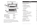
SUNSAVER MPPT
TM
WITH TRAKSTARTM MPPT TECHNOLOGY
Installation and Operation Manual
MAXIMUM POWER POINT TRACKING
Model: SS-MPPT-15L
1098 Washington Crossing Road
Washington Crossing, PA 18977 USA
www.morningstarcorp.com
Contents
34
SunSaver MPPT Dimensions
1.0 Important Safety Information
2.0 General Information
5
2.3 Optional Accessories
8
9
3.2 Configuration
10
3.3 Mounting
13
3.4 Wiring
15
4.1 LED Indications
12 Volts / 24 Volts
15 Amps
15 Amps
75 Volts
200 Watts
400 Watts
see Section 7.0 for full technical specifications
** Array voltage should never exceed maximum input voltage.
Refer to the solar module documentation to determine the highest expected array Voc as defined by the lowest expected ambient
9
3.1 General Installation Notes
4.0 Operation
System Voltage
Rated Battery Current
Rated Load Current
Max. Input Voltage**
Nominal Input Power
12 Volt System
24 Volt System
5
2.1 Overview
3.0 Installation Instructions
Specification Summary
4
20
20
4.2 TrakStarTM MPPT Technology
22
4.3 Battery Charging Information
25
4.4 Load Control Information
27
4.5 Protections
29
4.6 Inspection and Maintenance
31
4.7 Programming Custom Setpoints
32
5.0 Troubleshooting
33
5.1 Error Indications
33
5.2 Common Problems
34
6.0 Warranty
35
7.0 Technical Specifications
36
Appendix A - Wire Charts
41
temperature for the system location.
MORNINGSTAR CORPORATION
3
1.0 Important Safety Information
Save These Instructions
The following symbols are used throughout this manual to
indicate potentially dangerous conditions or mark important safety
instructions.
WARNING: Indicates a potentially dangerous
condition. Use extreme caution when
performing this task.
!
CAUTION: Indicates a critical procedure for
safe and proper operation of the controller.
NOTE: Indicates a procedure or function that
is important for the safe and proper operation of
the controller.
General Safety Information
• Read all of the instructions and cautions in the manual
before beginning installation.
• There are no user serviceable parts inside the
SunSaver MPPT. Do not disassemble or attempt to
repair the controller.
• Disconnect all sources of power to the controller before
installing or adjusting the SunSaver MPPT.
• There are no fuses or disconnects inside the SunSaver
MPPT. Install external fuses/breakers as required.
• Do not allow water to enter the controller.
• Confirm that power connections are tightened to avoid
excessive heating from a loose connection.
1.0 IMPORTANT SAFETY INFORMATION
Thank you for selecting the SunSaver MPPT charge
controller with TrakStar TechnologyTM. The SunSaver MPPT
(SS-MPPT) is an advanced maximum power point tracking
solar battery charger and load controller for stand-alone PV
systems. The controller features a smart tracking algorithm
that maximizes the energy from the solar module(s) and
also provides load control to prevent over-discharge of the
battery.
The SS-MPPT battery charging process has been
optimized for long battery life and improved system
performance. Self-diagnostics and electronic error protection
prevent damage when installation mistakes or system faults
occur. The controller also features four (4) settings switches
for adjustability, a meter port, and terminals for remote
battery temperature measurement (optional).
Although the SS-MPPT is very simple to configure and
use, please take the time to read this operator’s manual and
become familiar with the controller. This will help you make
full use of the many advantages the SS-MPPT can provide
for your PV system.
MORNINGSTAR CORPORATION
5
2.0
This manual contains important safety, installation and operating
instructions for the SunSaver MPPT solar controller.
2.0 General Information
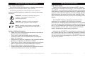
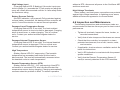
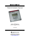
2.1 Overview
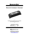
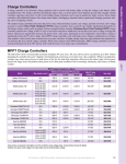
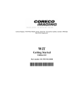
The features of the SunSaver MPPT are shown in Figure
1 below. An explanation of each feature is provided.
7
1
6
5
4
3
Figure 1. SunSaver MPPT features.
6 - Remote Temperature Sensor (RTS) Terminals
Connection point for a Morningstar RTS (optional) to
remotely monitor battery temperature.
7 - Local Temperature Sensor
Measures ambient temperature. Battery regulation is
adjusted based on ambient temperature unless an optional
RTS is installed.
8 - Battery Status LEDs
Provides approximate battery state of charge indication
and also indicates when a system or load fault condition
exists.
1 - Status LED
An LED indicator that shows charging status and also
indicates when a solar input fault condition exists.
2 - Power Terminal Block
Power terminations for system Solar, Battery, and Load
connections.
3 - Battery Select Jumper
A removable jumper to select the battery type.
4 - Meter Connection
A communication port for the Morningstar Remote Meter
or Personal Computer (PC) connection. A MSC adapter is
2.0 GENERAL INFORMATION
MORNINGSTAR CORPORATION
7
2.0
5 - Settings Switches
Adjustment switches that define the operating parameters
of the SunSaver MPPT.
8
2
required, available separately.
2.3 Optional Accessories
The following accessories are available for purchase
separately from your authorized Morningstar dealer.
Remote Temperature Sensor (Model: RTS)
Remote Meter (Model: RM-1)
The digital Remote Meter displays system operating information,
error indications, and self-diagnostic read-out. Information is
displayed on a backlit 4-digit custom LCD display. The large
numerical display and icons are easy to read and large buttons
make navigating the meter menus easy. Additionally, a status LED
and three (3) battery SOC LEDs provide system status at a glance.
The meter can be flush mounted in a wall or surface mounted
using the mounting frame (included). The RM-1 is supplied with 33
ft (10.0 m) of cable, a mounting frame, and mounting screws. The
RM-1 connects to the RJ- 11 Meter port on the SunSaver MPPT.
PC MeterBus AdapterTM (Model: MSC)
The MSC converts the MeterBus RJ-11 electrical interface to an
isolated standard RS-232 interface which enables communication
between the SunSaver MPPT and a personal computer (PC). The
MSC is required for programming custom charging setpoints and for
logging data. See Section 4.7 Programming Custom Setpoints or
visit Morningstar’s website for more information.
2.0 GENERAL INFORMATION
3.1 General Installation Notes
• Read through the entire installation section first before
beginning installation.
• Be very careful when working with batteries. Wear
eye protection. Have fresh water available to wash
and clean any contact with battery acid.
• Use insulated tools and avoid placing metal objects
near the batteries.
• Explosive battery gasses may be present during
charging. Be certain there is sufficient ventilation to
release the gasses.
• Do not install in locations where water can enter the
controller.
• Loose power connections and/or corroded wires
may result in resistive connections that melt wire
insulation, burn surrounding materials, or even cause
fire. Ensure tight connections and use cable clamps
to secure cables and prevent them from swaying in
mobile applications.
• Only charge lead-acid or NiCd batteries.
• The SunSaver MPPT Battery connection may be
wired to one battery or a bank of batteries. The following instructions refer to a singular battery, but it
is implied that the battery connection can be made
to either one battery or a group of batteries in a battery bank.
MORNINGSTAR CORPORATION
9
3.0
The RTS measures battery temperature for accurate temperature
compensation and is recommended when the ambient battery
temperature differs from the ambient controller temperature by
+/- 5 degrees C or more. An RTS can be attached to the SunSaver
MPPT at any time. The SunSaver MPPT will automatically use the
RTS for battery temperature compensation when installed. The
standard cable length is 33 ft (10 m), and can be extended to 100
ft (30 m) if required. Installation instructions are provided with the
RTS.
3.0 Installation Instructions
3.2 Configuration
The four (4) Settings Switches and the Battery Select
Jumper adjust the SS-MPPT battery type, load control,
equalization, and communication settings. This section
details the configuration for each setting.
Battery Type
Battery Jumper
Switch 1
Gel1
INSERTED
ON (↑)
Sealed
INSERTED
OFF (↓)
AGM1
REMOVED
ON (↑)
Flooded
REMOVED
OFF (↓)
(1) Setpoints for this battery type can be modified with custom programming. See Section 4.7 Programming Custom Setpoints for more information.
Table 1. Battery Type selection
3.0
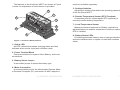
Select a Battery Type
The SS-MPPT provides four (4) different battery types
as shown in table 1 below. Use Settings Switch 1 and the
Battery Select Jumper to choose the battery type. See
Section 7.0 Technical Specifications for detailed charging
information for each battery type.
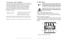
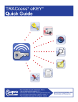
The battery select jumper is secured in the terminal block
between terminal #6 and terminal #7 as shown in figure 2.
The second column in table 1 specifies whether the jumper
should be removed or remain in place, depending on the
desired battery type.
Figure 2. Removing the Battery Select jumper.
Load Control – Low Voltage Disconnect / Reconnect
Choose between two (2) load control Low Voltage Disconnect / Reconnect settings.
SWITCH 2 OFF (↓):
SWITCH 2 ON (↑):
LVD = 11.50 V, LVR = 12.60 V
LVD = 11.00 V, LVR = 12.10 V 2
(2) These values can be modified with custom programming. See Section 4.7
Programming Custom Setpoints for more information.
Enable or Disable Auto-Equalization
Turn the auto-equalize feature OFF or ON. The autoequalize feature will administer an equalization charge
(flooded battery type only) every 28 days or if the battery
discharges too low the previous night. There is no
equalization charge for the gel or sealed battery type.
SWITCH 3 OFF (↓):
AUTO-EQUALIZE OFF
SWITCH 3 ON (↑):
AUTO-EQUALIZE ON
(agm, flooded battery type only)
3.0 INSTALLATION INSTRUCTIONS
MORNINGSTAR CORPORATION
11
SWITCH 4 OFF (↓):
MORNINGSTAR REMOTE METER
SWITCH 4 ON (↑):
MODBUS® PROTOCOL FOR
MSVIEW, 3RD PARTY DEVICES
(2) Morningstar PC Meterbus Adapter (Model: MSC) required. Not included.
See Morningstar’s website for more information. www.morningstarcorp.com.
MODBUS® is a registered trademark of Modbus-IDA (www.modbus-ida.org)
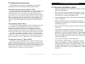
3.3 Mounting
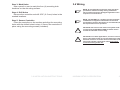
NOTE: When mounting the SunSaver MPPT, ensure free
air flow through the controller heat sink fins. There
should be at least 6 inches (150 mm) of clearance above
and below the controller to allow for cooling. If mounted
in an enclosure, ventilation is highly recommended.
WARNING: Risk of explosion! Never install the SunSaver
MPPT in a sealed enclosure with vented (flooded)
batteries! Do not install in a confined area where battery
gasses can accumulate.
Step 1: Choose Mounting Location
Locate the SunSaver MPPT on a vertical surface
protected from direct sun, high temperatures, and water.
Step 2: Check for Clearance
Place the SunSaver MPPT in the location where it will be
mounted. Verify that there is sufficient room to run wires and
that there is ample room above and below the controller for
air flow.
AT LEAST
6” (150 mm)
WARM AIR
AT LEAST
6” (150 mm)
COOL AIR
Figure 3. Mounting and cooling
3.0 INSTALLATION INSTRUCTIONS
MORNINGSTAR CORPORATION
13
3.0
Communication – Meter / MODBUS®
Choose the desired communication protocol for the RJ-11
meter connection. Select the Meter protocol to communicate
with a Morningstar Remote Meter (optional accessory).
Select the MODBUS® protocol to communicate with
a PC2 and Morningstar’s MSView software. MODBUS®
is an open communication protocol standard used by
Morningstar’s MSView PC software and other 3rd party
hardware / software.
Step 3: Mark Holes
Use a pencil or pen to mark the four (4) mounting hole
locations on the mounting surface.
3.4 Wiring
NOTE: A recommended connection order has been
provided for maximum safety during installation.
The controller will not be damaged regardless of the
sequence of connnections.
Step 4: Drill Holes
Remove the controller and drill 3/32” (2.5 mm) holes in the
marked locations.
3.0 INSTALLATION INSTRUCTIONS
!
CAUTION: The total current draw of all system loads
connected to the SS-MPPT LOAD terminals cannot
exceed the 15A load current rating.
!
CAUTION: For mobile applications, be sure to secure all
wiring. Use cable clamps to prevent cables from swaying
when the vehicle is in motion. Unsecured cables create
loose and resistive connections which may lead to
excessive heating and/or fire.
MORNINGSTAR CORPORATION
15
3.0
NOTE: The SS-MPPT is a negative ground controller. Any
combination of negative connections can be earth
grounded as required. Grounding is recommended, but
not required for correct operation.
Step 5: Secure Controller
Place the controller on the surface and align the mounting
holes with the drilled holes in step 4. Secure the controller in
place using the mounting screws (included).
Step 1: Load Wiring
The SS-MPPT load output connection will provide battery
voltage to system loads such as lights, pumps, motors,
and electronic devices. See Section 4.4 Load Control
Information for more details about load control.
Step 2: Battery Wiring
3.0
BATTERY
NEGATIVE (-)
BATTERY
POSITIVE (+)
25 AMP
FUSE
LOAD
POSITIVE (+)
25 AMP
FUSE
LOAD
NEGATIVE (-)
Figure 4. Load wiring
6 in (150 mm)
MAX.
+
-
12V / 24V
BATTERY
EARTH
GROUND
Figure 5. Battery wiring.
Connect load positive (+) and negative (-) load wires to
the system load(s) or load distribution panel as shown in
figure 4. Refer to the wire gauge chart on page 41 of this
manual for correct wire size.
If required, the negative load connection may be
earth grounded. Use appropriate gauge wire and proper
grounding methods for the installation site.
An in-line fuse holder should be wired in series in the load
positive (+) wire as shown. DO NOT INSERT A FUSE AT
THIS TIME.
If wiring the load connection to a load distribution panel,
each load circuit should be fused separately. The total load
draw should not exceed the 15 A load rating
3.0 INSTALLATION INSTRUCTIONS
Before connecting the battery, measure the battery
voltage. It must be over 7 volts to power the controller.
For 24 volt systems, the battery voltage must be greater
than 15.5 volts to properly detect a 24V battery. The 12/24
volt battery detection is automatic and the check is only
performed at start-up.
Connect the battery to the SS-MPPT. Refer to the wire
gauge chart on page 41 of this manual for correct wire size.
If required, the negative battery connection may be
earth grounded. Use appropriate gauge wire and proper
grounding methods for the installation site.
Wire an in-line fuse holder no more than 6 inches (150
mm) from the battery positive terminal. DO NOT INSERT A
FUSE AT THIS TIME.
MORNINGSTAR CORPORATION
17
Step 3: Solar Wiring
WARNING: Risk of electric shock! Exercise caution when
handling solar wiring. The solar array high voltage
output can cause severe shock or injury. Cover modules
from the sun before installing solar wiring.
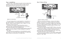
Step 5: Confirm Wiring
Double-check the wiring in steps 1 through 4. Confirm
correct polarity at each connection. Verify that all seven (7)
SS-MPPT power terminals are tightened.
36 V NOMINAL MAX.
12 Volt
MODULE
12 Volt
MODULE
12 Volt
MODULE
3
SOLAR
POSITIVE (+)
(-)
(+)
(-)
(+)
(-)
SOLAR
NEGATIVE (-)
(+)
EARTH
GROUND
Figure 6. Solar input wiring.
Connect the solar module(s) to the SS-MPPT. Refer to the
wire gauge chart on page 41 of this manual for correct wire
size.
If required, the negative solar connection may be
earth grounded. Use appropriate gauge wire and proper
grounding methods for the installation site.
3.0 INSTALLATION INSTRUCTIONS
+
-
2
1
Figure 7. System Wiring Review
Step 6: Install Fuses
Install a 25 Amp DC-rated fuse in each fuse holder in the
following order:
1. Load circuit
2. Battery circuit
Step 7: Confirm Power-up
The SS-MPPT should begin the power-up LED sequence
when battery power is applied. Observe that the Battery
Status LEDs blink in sequence one time.
If the SS- MPPT does not power up or a flashing LED
error sequence exists, refer to Section 6.0 Troubleshooting.
MORNINGSTAR CORPORATION
19
3.0
The SunSaver MPPT can accept 12 V , 24 V, or 36
V nominal off-grid solar module arrays. Grid-tie solar
module(s) may be used if the open circuit voltage (Voc) does
not exceed the SS-MPPT 75 Volt maximum solar input
rating. The solar module(s) nominal voltage must be equal
to or greater than the nominal battery voltage. For 24 V
systems, a 24 V or 36 V nominal solar array must be used.
Step 4: Accessories (optional)
Install the Remote Temperature Sensor and Remote
Meter (both purchased separately) if required. Refer to
the instructions provided with each accessory for detailed
installation procedures.
BATTERY SOC LEDS
4.0 Operation
4.1 LED Indications
Color
Indication
SOC LED
Indication
Battery Status
Load Status
Green
Fast Flashing
(2 Flash / sec)
Equalize Charge
Load On
Operating
State
Green
Med. Flashing
(1 Flash / sec)
Absorption Charge
Load On
Float Charge
Load On
Nearly Full
Load On
None
Off (with heartbeat¹)
Night
Green
Slow Flashing
(1 Flash / 2 sec)
Green
On Solid
( with heartbeat² )
Charging
Green
On solid
Red
Flashing
Error
Red
On Solid
( with heartbeat2 )
Critical Error
¹ heartbeat indication flickers the Status LED on briefly every 5 seconds
² heartbeat indication flickers the Status LED off briefly every 5 seconds
Table 2. Status LED definitions
For more information on Status LED errors, see Section
5.1 Error Indications.
4.0 OPERATION
Yellow
On solid
Half Full
Load On
Red
Flashing
(1 Flash / sec)
Battery Low
LVD Warning
(Load On)
Red
On solid
Battery Empty
LVD
(Load Off)
Table 3. Battery SOC LED definitions
!
CAUTION: An error condition exists if multiple Battery
SOC LEDs are flashing. See Section 5.1 Error Indications
for more information.
MORNINGSTAR CORPORATION
21
4.0
STATUS LED
The Status LED indicates charging status and any
existing solar input error conditions. The Status LED is on
when charging during the day and off at night. The Status
LED will flash red whenever an error condition(s) exists.
Table 2 lists the Status LED indications.
Three (3) battery “state of charge” LEDs indicate the
level of charge on the battery. The SOC indication is based
on battery voltage setpoints alone, which only provides an
approximation of the actual state of charge of the battery.
Table 3 lists the SOC LED indications.
The SS-MPPT utilizes Morningstar’s TrakStar Maximum
Power Point Tracking technology to extract maximum power
from the solar module(s). The tracking algorithm is fully
automatic and does not require user adjustment. Trakstar
technology will track the array maximum power point voltage
(Vmp) as it varies with weather conditions, ensuring that
maximum power is harvested from the array through the
course of the day.
(1)
(2)
Power Into the SS-MPPT = Power Out of the SS-MPPT
Volts In x Amps In = Volts Out x Amps Out
* assuming 100% efficiency. losses in wiring and conversion exist.
4.0 OPERATION
MAXIMUM
POWER
POINT
BATTERY
VOLTAGE
RANGE
{
If the solar module’s Vmp is greater than the battery
voltage, it follows that the battery current must be
proportionally greater than the solar input current so that
input and output power are balanced. The greater the
difference between the maximum power voltage and battery
voltage, the greater the current boost. Current boost can be
substantial in systems where the solar array is of a higher
nominal voltage than the battery as described in the next
section.
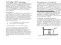
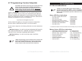
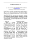
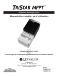
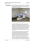
An Advantage Over Traditional Controllers
Traditional controllers connect the solar module directly
to the battery when recharging. This requires that the
solar module operate in a voltage range that is below the
module’s Vmp. In a 12 V system for example, the battery
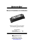
voltage may range from 10 - 15 Vdc but the module’s Vmp is
typically around 17 V. Figure 8 shows a typical current vs.
voltage output curve for a nominal 12V off-grid module.
10 V
15 V
~17 V
VOLTAGE
Figure 8. Nominal 12 V Solar Module I-V curve
MORNINGSTAR CORPORATION
23
4.0
Current Boost
In many cases, TrakStar MPPT technology will “boost” the
solar charge current. For example, a system may have 2
Amps of solar current flowing into the SS-MPPT and 5 Amps
of charge current flowing out to the battery. The SS-MPPT
does not create current! Rest assured that the power into
the SS-MPPT is the same as the power out of the SS-MPPT.
Since power is the product of voltage and current (Volts x
Amps), the following is true*:
High Voltage Strings and Grid-tie Modules
Another benefit of TrakStar MPPT technology is the ability
to charge 12 Volt or 24 Volt batteries with solar arrays of
higher nominal voltages. A 12V battery bank can be charged
with a 12 V, 24 V, or 36 V nominal off-grid solar array.
Certain grid-tie solar modules may also be used as long
as the solar array open circuit voltage (Voc) rating will not
exceed the SS-MPPT 75 V maximum input voltage rating at
worst-case (coldest) module temperature. The solar module
documentation should provide Voc vs. temperature data.
Higher solar input voltage results in lower solar input
current for a given input power. High voltage solar input
strings allow for smaller gauge solar wiring. This is
especially helpful for systems with long wiring runs between
the solar array and the SS-MPPT.
CURRENT
4.2 TrakStarTM MPPT Technology
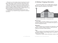
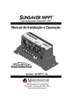
4.3 Battery Charging Information
The SunSaver MPPT has a 4-stage battery charging
algorithm for rapid, efficient, and safe battery charging.
Figure 9 shows the sequence of the stages.
EQUALIZE
4.0
VOLTAGE
The array Vmp is the voltage where the product of current
and voltage (Amps x Volts) is greatest, which falls on the
“knee” of the solar module I-V curve as shown in Figure 8.
Because Traditional controllers do no operate at the Vmp
of the solar array, energy is wasted that could otherwise be
used to charge the battery and power system loads. The
greater the difference between battery voltage and the Vmp
of the module, the more energy is wasted.
TrakStar MPPT technology will always operate at the
Vmp resulting in less wasted energy compared to traditional
controllers.
NIGHT
BULK
CHARGE
ABSORPTION
FLOAT
NIGHT
TIME
Figure 9. SunSaver MPPT charging algorithm
Bulk Charge
In this stage, the battery voltage has not yet reached
absorption voltage and 100% of available solar power is
used to recharge the battery.
Absorption
When the battery has recharged to the Absorption voltage
setpoint, constant-voltage regulation is used to prevent
heating and excessive battery gassing.
Float
After the battery is fully charged the SS-MPPT reduces
the battery voltage to a float charge which is sometimes
called a trickle charge.
Depending on battery history, the battery remains in the
4.0 OPERATION
MORNINGSTAR CORPORATION
25
absorption stage for 3 or 4 hours before transitioning to the
float stage.
Equalize (flooded battery type only)
If the auto-equalize feature is enabled, the SS-MPPT
will equalize a flooded battery for three (3) hours every 28
days. Equalize charging raises the battery voltage above
the standard absorption voltage so that the electrolyte
gasses. This process prevents electrolyte stratification and
equalizesthe individual cell voltages within the battery.
4.4 Load Control Information
The primary purpose of the load control function is to
disconnect system loads when the battery has discharged
to a low state of charge and reconnect system loads when
the battery is sufficiently recharged. System loads may be
lights, pumps, motors, DC appliances, and other electronic
devices. The total current draw of all loads must not exceed
the SS-MPPT 15 Amp maximum load rating.
CAUTION: Do not wire an AC inverter of any size to the
load terminals of the SunSaver MPPT. Damage to the
load control circuit may result. Wire inverters directly to
the battery or battery bank.
Load Control Settings
Load control is fully automatic. Choose between two (2)
factory Low Voltage Disconnect (LVD) and Low Voltage
Reconnect (LVR) settings by adjusting switch #2. See
Section 3.2 Configuration for more information.
Current Compensation
All LVD and LVR setpoints are current compensated.
Under load the battery voltage will sag in proportion to the
current draw of the load. A short-term large load could cause
a premature LVD without the current compensation feature.
LVD and LVR setpoints are adjusted lower per the following
table.
System Voltage
Current Compensation
12 Volt
-15 mV per amp of load
24 Volt
-30 mV per amp of load
Table 4. Current compensation values.
4.0 OPERATION
MORNINGSTAR CORPORATION
27
4.0
!
If the battery discharges to the LVD setpoint the load will
disconnect and a solid red Battery Status LED indication
will be displayed.
General Load Control Notes
•
A 15 V maximum regulation voltage limit (30 V @ 24 V
nominal) exists for all battery types. This limit ensures
that the battery and load terminal voltages will never
exceed 15 V/30 V. This protects certain DC loads that
may be damaged by high input voltage.
•
•
Do not wire multiple SunSaver MPPT load outputs
together in parallel to power DC loads with a current
draw greater than 15A. Equal current sharing cannot
be guaranteed and an over-load condition will likely
occur on one or more controllers.
Exercise caution when connecting loads with specific
polarity to a live load circuit. A reverse polarity connection may damage the load. Always double check load
connections before applying power.
4.0 OPERATION
4.5 Protections
Solar Overload
(No LED indication) The SunSaver MPPT will limit battery
current to the 15 Amp maximum rating. An over-sized
solar array will not operate at peak power. The solar array
should be less than the SS-MPPT nominal max. input power
rating for optimal performance. See Section 7.0 Technical
Specifications for more information.
Load Overload
(Battery Status LEDs: R/Y-G sequencing) If the load
current exceeds the maximum load current rating, the SSMPPT will disconnect the load. The greater the overload the
faster the load will be disconnected. A small overload could
take a few minutes to disconnect.
The SS-MPPT will attempt to reconnect the load two (2)
times. Each attempt is approximately 10 seconds apart. If
the overload remains after two (2) attempts, the load will
remain disconnected until power is removed and reapplied.
Solar Short Circuit
(Charging Status LED: OFF) Solar input power wires are
short-circuited. Charging automatically resumes when the
short is cleared.
Load Short Circuit
(Battery Status LEDs: R/Y-G sequencing) Fully protected
against load wiring short-circuits. After two (2) automatic
load reconnect attempts (10 seconds between each
attempt), the fault must be cleared by removing and
reapplying power.
MORNINGSTAR CORPORATION
29
4.0
LVD Warning
As the battery discharges the Battery Status LEDs will
transition from green to yellow and then from yellow to
flashing red. The flashing red indication is a warning that a
low voltage disconnect event will occur soon. The amount of
time between a green SOC indication and load disconnect
will depend on many factors including:
•
rate of discharge (amount of load draw)
•
capacity of the battery
•
health of the battery
•
LVD setpoint
High Voltage Input
(Charging Status LED: R flashing) If the solar input open
circuit voltage (Voc) exceeds the 75 volt maximum rating the
array will remain disconnected until the Voc falls safely below
the maximum rating.
Battery Reverse Polarity
(No LED indication, not powered) Fully protected against
reverse battery connection. No damage to the controller will
result. Correct the miswire to resume normal operation.
Damaged Internal Temperature Sensor
(Charging Status LED: R on solid) The internal heatsink
temperature sensor is damaged. This is a critical error.
Contact your authorized Morningstar dealer for service.
High Temperature
(Battery Status LED: R-Y sequencing) The heatsink
temperature has exceeded safe limits and the load is
disconnected. The load will automatically reconnect when
the heatsink cools to a safe temperature.
High Voltage Transients
Solar, battery, and load power connections are protected
against high voltage transients. In lightning prone areas,
additional external suppression is recommended.
4.6 Inspection and Maintenance
The following inspections and maintenance tasks are
recommended at least two times per year for best controller
performance.
• Tighten all terminals. Inspect for loose, broken, or
corroded connections.
• Verify that all wire clamps and tie-downs are secure.
• Check that the controller is mounted in a clean,
protected environment; free of dirt, insects, nests,
and corrosion.
• If applicable, check enclosure ventilation and air flow
holes for obstructions.
• Verify LED indication is consistent with the present
system conditions.
• Verify that the Remote Temperature Sensor (if
used) is securely attached to the RTS terminals.
Remote Temperature Sensor (RTS)
(Battery Status LED: R/Y - G/Y sequencing) A bad RTS
connection or a severed RTS wire has disconnected the
temperature sensor during charging. Charging automatically
resumes when the problem is fixed. To resume operation
4.0 OPERATION
MORNINGSTAR CORPORATION
31
4.0
Damaged Local Temperature Sensor
(Charging Status LED: R on solid) The local ambient
temperature sensor is short-circuited or damaged. Charging
stops to avoid over- or under-charging. This is a critical
error. Contact your authorized Morningstar dealer for
service.
without a RTS, disconnect all power to the SunSaver MPPT
and then reconnect.
4.7 Programming Custom Setpoints
!
CAUTION: This feature should only be used by advanced
users who have very specific charging and/or load
control requirements that are not met using the factory
default charge and load control settings. The factory
default settings will be sufficient for the vast majority of
users.
Custom charging and load setpoints can be programmed into SSMPPT non-volatile memory using a PC with Morningstar MSView
software installed and a Meterbus to Serial Adapter (model: MSC).
Refer to the MSView help files for detailed instructions. MSView PC
software is available for free on our website at:
http://www.morningstarcorp.com/
To use custom setpoints, the Settings Switches must be adjusted as
follows:
SWITCH #1 ON (↑) TO USE CUSTOM CHARGING SETPOINTS.
USE THE BATTERY SELECT JUMPER TO SELECT BETWEEN
TWO SETS OF CUSTOM CHARGING SETPOINTS.
SWITCH #2 ON (↑) TO USE CUSTOM LOAD CONTROL
SETPOINTS.
NOTE: Programming custom setpoints will overwrite the
default Gel and AGM battery type values programmed
into custom memory at the factory. Document the new
custom values in this manual for future reference.
5.0 TROUBLESHOOTING
NOTE: If an optional Morningstar Remote Meter is
attached to the SunSaver MPPT , use the self-diagnostic
feature to determine the cause of the error indication.
Refer to the Remote Meter Operator’s Manual for more
information.
Status LED Error Indications
•
•
•
•
•
•
•
PV High Voltage Disconnect
RTS Shorted
RTS Disconnected
Damaged local temp. sensor
Damaged heatsink temp. sensor
Damaged input MOSFETs
Firmware Error
Flashing Red
Flashing Red
Flashing Red
Solid Red1
Solid Red1
Solid Red1
Solid Red1
5.0
A setup wizard will guide you through the setpoint configuration
process. Refer to MSView help files for more information.
5.0 Troubleshooting
5.1 Error Indications
1 - heartbeat indication flickers the Status LED off briefly every 5 seconds
Battery Status LED Error Indications
•
•
•
•
•
•
•
•
Load High Voltage Disconnect
High Temperature Disconnect
Remote Temp. Sensor Error
External Wiring Error
Load Overcurrent
Load Short Circuit
Custom Setpoints Update
Self-test Error
MORNINGSTAR CORPORATION
R-G Sequencing
R-Y Sequencing
Y/R - G/Y Sequencing
G/R-Y Sequencing
Y/R-G Sequencing
G/R-Y Sequencing
G/Y/R Flashing
R-Y-G Sequencing
33
5.2 Common Problems
6.0 Warranty
Problem: No LED indications
Solution: With a multi-meter, check the voltage at the
battery terminals on the SS-MPPT. Battery voltage must be
at least 7V to power the SS-MPPT.
Problem: The SS-MPPT is not charging the battery.
Solution: If the Status LED is solid or flashing red,
see Section 5.1 Error Indications. If the Status LED is off,
measure the voltage across the Solar input terminals of
the SS-MPPT. Input voltage must be greater than battery
voltage. Check fuses and solar wiring connections. Check
solar array for shading.
Full testing documentation is available on our website at:
CLAIM PROCEDURE
Before requesting warranty service, check the Operator’s Manual to
be certain that there is a problem with the controller. Return the defective
product to your authorized Morningstar distributor with shipping charges
prepaid. Provide proof of date and place of purchase.
To obtain service under this warranty, the returned products must include
the model, serial number and detailed reason for the failure, the module type,
array size, type of batteries and system loads. This information is critical to a
rapid disposition of your warranty claim.
Morningstar will pay the return shipping charges if the repairs are covered
by the warranty.
WARRANTY EXCLUSIONS AND LIMITATIONS
This warranty does not apply under the following conditions:
• Damage by accident, negligence, abuse or improper use.
• PV or load currents exceeding the ratings of the product.
• Unauthorized product modification or attempted repair.
• Damage occurring during shipment.
6.0
http://support.morningstarcorp.com/
The SunSaver MPPT charge controller is warranted to be free from defects
in material and workmanship for a period of FIVE (5) years from the date of
shipment to the original end user. Morningstar will, at its option, repair or
replace any such defective products.
THE WARRANTY AND REMEDIES SET FORTH ABOVE ARE
EXCLUSIVE AND IN LIEU OF ALL OTHERS, EXPRESS OR IMPLIED.
MORNINGSTAR SPECIFICALLY DISCLAIMS ANY AND ALL IMPLIED
WARRANTIES, INCLUDING, WITHOUT LIMITATION, WARRANTIES OF
MERCHANTABILITY AND FITNESS FOR A PARTICULAR PURPOSE.
No Morningstar distributor, agent or employee is authorized to make any
modification or extension to this warranty.
MORNINGSTAR IS NOT RESPONSIBLE FOR INCIDENTAL OR
CONSEQUENTIAL DAMAGES OF ANY KIND, INCLUDING BUT NOT
LIMITED TO LOST PROFITS, DOWNTIME, GOODWILL OR DAMAGE TO
EQUIPMENT OR PROPERTY.
1098 Washington Crossing Road,
Washington Crossing, PA 19877 USA
Email: [email protected]
Website: www.morningstarcorp.com
5.0 TROUBLESHOOTING
MORNINGSTAR CORPORATION
35
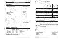
Battery Setpoints (@ 25°C)
7.0 Technical Specifications
1.0 %
2.0 %
6-pin RJ-11
4 x 1500 W
Battery Status LEDs
Falling V
G to Y
12.1
Y to Flash R 11.7
Flash R to R 11.5
Rising V
13.1
Y to G
12.6
Flash R to Y
12.6
R to Y
Note: Multiply x2 for 24 Volt systems.
7.0 TECHNICAL SPECIFICATIONS
14.0 V
14.1 V
14.3 V
14.4 V
Float Voltage
13.7 V
13.7 V
13.7 V
13.7 V
Time until Float
3 hr
3 hr
3 hr
3 hr
Equalize Voltage
N/A
N/A
14.5 V
14.9 V
Equalize Duration
N/A
N/A
3 hrs
3 hrs
Equalize Calendar
N/A
N/A
28
days
28
days
1
15 V / 30 V
Low Voltage Disconnect2
11.5 V / 11.0 V
Low Voltage Reconnect2
12.6 V / 12.1 V
Not temperature compensated. 15 V @ 12 V nominal, 30 V @ 24 V nominal
2
Adjustable by switch, not temperature compensated. 11.0 V / 12.1 V setting
can be modified in custom settings.
1
NOTE: Temperature compensation increases regulation
voltage in cold temperature. A 15 V (30 V @ 24 V nominal)
maximum battery voltage limit prevents damage to
sensitive DC loads.
Environmental
Ambient Temperature Range
Storage temperature
Humidity
Enclosure
MORNINGSTAR CORPORATION
-40°C to +60°C
-55°C to +100°C
100% N.C.
IP10 (indoor)
37
7.0
Temp. Compensation Range
Temp. Compensated Setpoints
4 stage
-5 mV / °C / cell
(25°C reference)
- 30°C to + 60°C
Absorption
Float
Equalize
Absorption Voltage
Max. Regulation Voltage
Battery Charging
Regulation Method
Temp. Compensation Coefficient
Flooded
200 Watts
400 Watts
35 mA
AGM
12 or 24 Vdc
15 A
7 V – 36 V
75 V
Sealed
Nominal system voltage
Max. battery current
Battery voltage range
Max. solar input voltage
Nominal Max. Input Power
12 Volt
24 Volt
Self-consumption
Accuracy
Voltage
Current
Meter Connection
Transient Surge Protection
Gel
Electrical
Mechanical
Power terminals wire size (max.)
Solid
Multistrand
Fine strand
Terminal Diameter
Power terminals torque (max.)
RTS terminals wire size (max.)
Wire gauge (min)
Wire gauge (max)
RTS terminals torque (max.)
Dimensions
Weight
#6 AWG / 16 mm2
#6 AWG / 16 mm2
#8 AWG / 10 mm2
0.210 in / 5.4 mm
35 in-lb / 4 Nm
#22 AWG / 0.3 mm2
#12 AWG / 3.0 mm2
0.4 Nm / 3.5 in-lb
see inside front cover
1.3 lbs / 0.60 kg
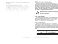
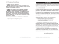
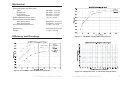
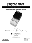
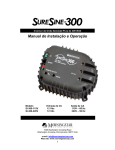
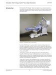
Efficiency and Deratings
Figure 11. SS-MPPT 24 Volt Efficiency Curves
7.0
Figure 10. SS-MPPT 12 Volt Efficiency Curves
7.0 TECHNICAL SPECIFICATIONS
Figure 12. Output Current vs. Heatsink Temperature
MORNINGSTAR CORPORATION
39
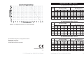
Appendix A - Wire Charts
12 Volt Nominal Wire Chart
One-way Wire Distance (feet)
Wire Gauge (AWG)
amps
One-way Wire Distance (meters)
Wire Gauge (mm2)
14
12
10
8
6
2.0
3.0
5.0
8.0
13.0
2
70
112
180
287
456
21
34
55
87
139
4
35
56
90
143
228
11
17
27
44
69
8
18
28
45
72
114
5
8
14
22
35
12
12
19
30
48
76
4
6
9
15
23
15
9
15
24
38
61
3
5
7
12
19
3% Voltage drop, Annealed copper wire at 20°C
24 Volt Nominal Wire Chart
Figure 13. Output Current vs. Array Voltage
One-way Wire Distance (feet)
Wire Gauge (AWG)
amps
One-way Wire Distance (meters)
Wire Gauge (mm2)
14
12
10
8
6
2.0
3.0
5.0
8.0
13.0
2
140
224
360
574
912
43
68
110
175
278
4
70
112
180
286
456
21
34
55
87
139
8
36
56
90
144
228
11
17
27
44
69
12
24
38
60
96
152
7
12
18.3
29
46
9
15
23
37
18
30
48
76
122
5
15
3% Voltage drop, Annealed copper wire at 20°C
36 Volt Nominal Wire Chart
Specifications subject to change without notice.
Designed in the U.S.A.
Assembled in Taiwan
One-way Wire Distance (feet)
Wire Gauge (AWG)
amps
© 2008 Morningstar Corporation
MS-ZMAN-SSPPT-A
v02
7.0 TECHNICAL SPECIFICATIONS
One-way Wire Distance (meters)
Wire Gauge (mm2)
14
12
10
8
6
2.0
3.0
5.0
8.0
13.0
2
210
336
540
861
1368
64
102
165
262
417
4
105
168
270
429
684
32
51
82
131
208
8
54
84
135
216
342
16
26
41
66
104
12
36
57
90
144
228
11
17
27
44
69
27
45
72
114
183
8
15
3% Voltage drop, Annealed copper wire at 20°C
14
22
35
56
MORNINGSTAR CORPORATION
41