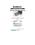
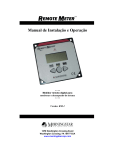
1
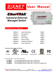
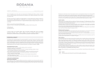
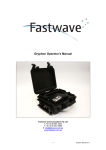
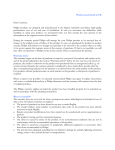
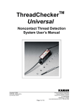
SUNKEEPER
TM
Solar Charge Controller
Installation and Operation
Manual
….
Junction Box ( J-Box) Mounted Solar Controller
….
Models
……………………………….…………
SunKeeper-6
6A / 12V
SunKeeper-12
12A / 12V
1098 Washington Crossing Road
Washington Crossing, PA 18977 USA
www.morningstarcorp.com
Table of Contents
1.0 Safety Instructions
2.0 Installation
2.1 Installation Notes
2.2 Mounting to a J-box
2.3 Surface Mounting
3.0 LED Indications
4.0 Operation
4.1 Operator’s Tasks
4.2 Charging Algorithm
4.3 Charging Features
4.4 Protections
5.0 Inspection and Maintenance
6.0 Troubleshooting
6.1 Testing for Correct Operation
6.2 Flashing Red LED
6.3 Solid Red LED
7.0 Warranty
8.0 Technical Specifications
2
3
4
4
6
9
12
13
13
13
14
15
16
17
17
19
20
21
22
1.0 Safety Instructions
SAVE THESE INSTRUCTIONS – This manual
contains important instructions that should be followed
for proper installation and maintenance.
Read all of the instructions and cautions in the manual
before starting the installation.
WARNING – Be very careful when working with
batteries. Lead-acid batteries can generate explosive
gases, and short circuits can potentially draw hundreds
or thousands of amps from the battery.
Do not exceed the voltage or current ratings of the
controller. Use only with a 12V battery.
There are no user serviceable parts in the SunKeeper.
Do not disassemble or attempt to repair.
The negative system conductor should be properly
grounded per U.S. National Electric Code (NEC)
guidelines for most effective lightning protection.
3
2.0 Installation
2.1 Installation Notes
Hazardous Locations: The SunKeeper family of
charge controllers has been listed to UL1604 and CSA
22.2 No.213-M1987 for use in Class 1, Division 2,
Groups A, B, C and D hazardous locations. In order to
comply with the UL and CSA standards, the installation
should follow the requirements of the National
Electrical Code Article 501-4(b) and/or Canadian
Electrical Code Article 18-156 when installing a
SunKeeper in a Hazardous (Classified) Location.
System Wiring: Use copper wire only. Power
conductors should be joined or spliced using insulated
butt splice solderless crimp connectors or by brazing,
welding, or soldering wire ends. If soldered, the
spliced joint should be mechanically and electrically
secure before soldering. All splices and joints should
be covered with insulation equivalent to that of the
conductors.
System Fusing: The battery positive lead should be
fused no further than 12 inches (305 mm) from the
battery.
SK-6
SK-12
8A fuse
16A fuse
4
Temperature Compensation Select: The SunKeeper
has three temperature compensation options. The blue
Temperature Compensation Loop can be configured
for the following temperature compensation options:
♦
♦
♦
Loop not cut: Internal temperature sensor used
for temperature compensation (factory
default).
Loop cut, left open: No temperature
compensation. Insulate/cap loose ends.
Loop cut, connected to RTS: Remote
Temperature Sensor (RTS)* used for
temperature compensation.
* The RTS is an optional Morningstar accessory
purchased separately. Only use a Morningstar RTS
with the SunKeeper.
Cover the Solar Module(s): Keep the solar module
out of sunlight or covered with an opaque sheet until
installation is complete.
SunKeeper Wire Lead Definitions:
Solar +
Battery +
Common Negative
RTS Option
Yellow
Red
Black
Blue Loop
NOTE: The RTS connection has no polarity. The red
and black RTS wires may be wired to either of the blue
Temperature Compensation Loop leads.
5
2.2 Mounting to a J-box
NOTE: Complete steps 1 through 7 before mounting
the solar module.
SOLAR MODULE
( BOTTOM VIEW )
J-BOX
CONDUIT
FUSE
-
+
RTS
BATTERY
Figure 1. Typical System
1. Remove the solar module j-box cover (refer to
solar module documentation if necessary).
2. Unscrew the SunKeeper locknut and remove the
plastic mounting feet. Store the mounting feet in a
safe place. They are not needed when mounting to
a j-box.
6
3. On the solar module j-box: choose knockouts or
drill 7/8 inches (22.2 mm) holes for the SunKeeper
and ½” conduit entry into the j-box. If drilling holes,
choose locations that will allow easy wiring access
to the solar module power terminals and easy exit
into the ½” conduit.
4. Insert the SunKeeper leads into the chosen
knockout or drilled hole.
5. Thread the SunKeeper leads through the locknut
and slide the locknut down to meet the threaded
neck of the SunKeeper.
6. Screw the locknut hand-tight onto the threaded
neck of the SunKeeper. The rubber o-ring should
seat firmly against the j-box outside wall around
the perimeter of the hole forming a watertight seal.
When satisfied that a good seal is made, fully
tighten the locknut.
7. Pull 2 cables for battery positive and battery
negative as well as the RTS sensor lead (if using
an RTS) through the conduit.
8. On the SunKeeper: select the temperature
compensation configuration required (Refer to
section 2.1: Installation Notes -Temperature
Compensation Select) .
If using an RTS:
a. Cut the blue Temperature Compensation Loop
on the SunKeeper in the middle of the loop
creating two (2) equal length wire leads.
7
Figure 2. J-Box Wiring
8
b. Strip ½” (13 mm) of insulation off each of the
leads.
c. Crimp or splice the two (2) blue wire leads to
the two RTS wires (red & black). Polarity is
not important. Refer to section 2.1: Installation
Notes - System Wiring.
9. Wire the SunKeeper as shown in Figure 2. Wiring
may differ slightly depending on the solar module
manufacturer. Terminal locations and the number
of terminals may also differ. Splices may not be
necessary if extra junction terminals are provided.
Refer to the documentation supplied with the solar
module.
10. In the battery box, wire an in-line fuse holder and
fuse to the Battery + cable. Connect the battery
cables to the battery lugs. Refer to section 2.1:
Installation Notes - System Fusing.
11. If a Morningstar RTS is used, secure the RTS
terminal lug to a battery lug.
12. Uncover the solar module and replace the j-box
cover.
2.3 Surface Mounting
CAUTION: To conform to Class 1, Division 2 Group
A,B,C,D hazardous location requirements, the
SunKeeper and wiring must be contained inside an
approved enclosure.
9
1. Plastic mounting feet are included with the
SunKeeper to allow for surface mounting.
Figure 3. Mounting Feet Assembly
2. Assemble the SunKeeper, mounting feet, and
locknut as shown in Figure 3.
3. Place the SunKeeper on the surface where it will
be mounted and determine where the wires will be
routed. Be sure there is sufficient bending room for
the wires. With a pen or pencil, mark the location
of the screws.
4. With a drill and 1/8” (3 mm) bit, drill pilot holes for
both mounting screws where marked in step three
(3).
10
5. Place the SunKeeper onto the surface and align
the two (2) mounting feet slots with the pilot holes.
Use #10 (M5) pan-head screws (not supplied) to
secure the SunKeeper to the surface.
6. On the SunKeeper: select the temperature
compensation configuration required (Refer to
section 2.1: Installation Notes - Temperature
Compensation Select) .
If using an RTS:
a. Cut the blue Temperature Compensation
Loop on the SunKeeper in the middle of
the loop creating two (2) equal length wire
leads.
b. Strip ½” (13 mm) of insulation off each of
the leads.
7. Wire the SunKeeper to the RTS (if used) and the
solar module. Refer to section 2.1: Installation
Notes – SunKeeper Wire Definitions.
8. In the battery box, wire an in-line fuse holder and
fuse to the Battery + cable. Connect the battery
cables to the battery lugs. Refer to section 2.1:
Installation Notes - System Fusing.
9. If a Morningstar RTS is used, secure the RTS
terminal lug to a battery lug.
10. Uncover the solar module.
11
3.0 LED Indications
Green LED (blinks 3 times): Indicates correct
installation. Displayed at installation start up (when
solar or battery power is first applied).
Green LED (ON): Bulk charging stage. Solar power is
available and the battery is being charged. A single
blink of the green LED every 5 seconds indicates that
the SunKeeper is still operational.
Green LED (fast blinking): Regulation / Float stage.
The battery has charged to Regulation voltage, solar
power is being limited to prevent over-charge. When
the battery is fully charged at Regulation voltage, the
SunKeeper will transition to Float stage and the green
LED will continue blinking.
No LED (OFF): Night condition. No solar power is
available for charging. The SunKeeper is in sleep
mode until solar power becomes available. A single
blink of the green LED every 5 seconds indicates that
the SunKeeper is still powered and operational.
Red (blinking) LED: System installation error and/or
operation fault. See Section 6.2 in Troubleshooting.
Red (ON) LED: Critical fault. See Section 6.3 in
Troubleshooting.
12
4.0 Operation
4.1 Operator’s Tasks
The SunKeeper is a fully automatic solar charge
controller that includes many electronic functions to
protect both the controller and the system.
The only manual tasks performed by the operator
are:
a. Installation (see section 2.0)
b. Temperature Compensation selection (see
section 2.1 – Temperature Compensation
Select)
c. Routine Maintenance (see section 5.0)
4.2 Charging Algorithm
The SunKeeper battery charging algorithm is optimized
for sealed lead-acid batteries. There are four main
stages to the charging algorithm:
Night – There is no solar power available, the
solar module is disconnected from the battery to
prevent nighttime reverse current leakage.
Bulk Charge – Solar power is available, the
battery is recharging and has not yet reached full
state-of-charge.
Regulation – The battery has charged to the
Regulation setpoint, the SunKeeper is limiting
13
solar charging current to prevent battery overcharge while bringing the battery to full state-of –
charge.
Float – The battery has reached full state-ofcharge and the SunKeeper has reduced battery
voltage to the lower Float setpoint.
4.3 Charging Features
Temperature Compensation - Lead-acid battery
chemistry changes with temperature. The
SunKeeper adjusts the Regulation and Float
voltage setpoints as temperature changes so that
the battery is correctly charged. The user may
choose to add an RTS (purchased separately), or
use the internal temperature sensor. Temperature
compensation can also be disabled. See section
2.1 for more information.
Maximum Charge Voltage – The SunKeeper
limits the charge voltage to 15V, regardless of
ambient temperature, so that voltage-sensitive DC
loads are not damaged.
Night Disconnect – The SunKeeper periodically
checks for nighttime condition. When night is
detected, the SunKeeper disconnects the solar
module to prevent reverse current leakage. An
external blocking diode is not required.
14
4.4 Protections
The SunKeeper is fully protected against system faults
listed below. Recovery is automatic except where
noted below. Refer to section 3.0 for fault LED
indications.
Reverse Polarity Solar (LED OFF) – no charging,
disconnects solar module until wired with correct
polarity.
Reverse Polarity Battery (red blinking LED) – no
charging, displays fault until battery wired with correct
polarity.
Short Circuit Solar (LED OFF) – stops charging until
short clears or will enter Night stage (LED OFF) if fault
persists.
Charging Over-current (red blinking LED) –
charging current has exceeded SunKeeper current
rating; fully automatic recovery; retry every 10
seconds.
High Temperature Condition (red blinking LED) –
ambient temperature is too high; charging
automatically resumes when SunKeeper has cooled to
a safe temperature.
Temperature Sensor Failure (red blinking LED) –
detects a failure in the SunKeeper’s internal
temperature sensor or a disconnect of the Remote
Temperature Sensor (if used). Fault persists until the
problem is corrected.
15
5.0 Inspection and Maintenance
The following inspections and maintenance tasks are
recommended at least once per year for best controller
performance.
9
Inspect for loose or broken connections at the
battery. If an RTS is installed, be sure the RTS
terminal lug is secured to a battery terminal.
9
Check the wires and cables for frays, pinches, or
other insulation damage.
9
Inspect the SunKeeper plastic case for damage.
9
Verify that the o-ring still maintains a seal against
the j-box outside wall.
9
Open the solar module j-box and inspect for water
ingress. Also inspect the j-box wiring for corrosion
and loose connections.
9
Check that the SunKeeper functions and the LED
indicator are correct for the system conditions at
that time.
16
6.0 Troubleshooting
The SunKeeper continuously monitors for system
faults (blinking red LED) and critical SunKeeper
internal circuit faults (solid red LED). This section
explains how to test a SunKeeper for correct operation
and provides troubleshooting checklists for both types
of faults.
6.1 Testing for Correct Operation
The SunKeeper operation can be verified by simply
measuring a few voltages. You will need a volt or multimeter to take voltage measurements. If testing the
SunKeeper on a bench, a power supply which is
current limited to 2A and 15V can be used instead of a
solar module.
1. Disconnect the battery and solar module from
the SunKeeper.
2. Connect a battery (11V or more) to the
SunKeeper battery leads. Verify that the LED
blinks green 3 times on power-up. The LED
should remain off after start-up (Night condition).
3. Measure the voltage on the SunKeeper Solar
input leads (Solar + to Common -). The voltage
on the Solar input leads should be approximately
half of the measured battery voltage. If the
voltage is zero volts or about the same as
17
battery voltage, there is a problem with the
SunKeeper.
4. Disconnect the battery.
5. Connect the solar module (in full sun) to the
SunKeeper Solar input leads. The LED should
blink 3 times. After a few seconds the LED
should begin blinking green (Regulation).
6. Measure the output voltage on the open Battery
leads (Battery + to Common -). Voltage should
exist on the Battery leads, however the output
voltage will NOT be 14.1V. The output voltage
is a pulsed waveform. The multimeter will display
the average or RMS of the waveform. If there is
no voltage output, the SunKeeper may be
damaged.
7. Keep the solar module connected and connect
the battery to the Battery output leads. If the
SunKeeper is in Bulk charge (solid green LED),
the voltage on the Solar Input terminals should
be the same as the voltage on the Battery output
leads. If the SunKeeper is in Regulation (blinking
green LED), the battery voltage should be
maintained at full charge voltage.
18
6.2 Flashing Red LED
Installation Error or Operation Fault
(SunKeeper is not damaged)
A red flashing LED indicates that a fault exists in the
system or the SunKeeper faulted during operation.
Corrective action is needed. Check the system for the
following conditions:
Reverse Battery – The battery connection is
reversed at the SunKeeper or at the battery
terminals. Disconnect the battery connection at the
SunKeeper and measure the voltage with a
voltmeter. Verify correct polarity. Connecting the
battery with correct polarity will clear the fault
condition.
RTS Disconnected – If a Remote Temperature
Sensor is wired to the SunKeeper, the cable may
be pinched or broken. Inspect the RTS cable and
connections for frays or breaks. Properly
reconnecting the RTS will clear the fault condition.
Over-current Condition – The charging current
exceeds the current rating of the SunKeeper. Be
sure that the solar output from the solar module(s)
does not exceed the 6A (SK-6) or 12A (SK-12)
maximum charge current rating.
High Temperature Disconnect – The SunKeeper
internal temperature has exceeded safe limits.
This fault condition will automatically clear when
19
the SunKeeper internal temperature has cooled to
a safe operating temperature.
6.3 Solid Red LED
Critical Faults
(SunKeeper may be damaged)
If the SunKeeper Status LED indicates a Solid Red
critical fault, the SunKeeper should be removed from
service immediately.
Internal Temperature Sensor Failure – The
internal temperature sensor has failed. The
SunKeeper can no longer monitor internal
temperature, which is critical for proper battery
charging.
Damaged Power Transistors – Power transistors
switch the charging current in the SunKeeper. If
the power transistors or the circuitry that control
them is damaged, the SunKeeper can no longer
control current. The SunKeeper may over-charge
the battery or not allow any charging current.
20
7.0 Warranty
The SunKeeper is warranted to be free from defects in material and
workmanship for a period of FIVE (5) years from the date of
shipment to the original end user. Morningstar will, at its option,
repair or replace any such defective products.
CLAIM PROCEDURE
Before requesting warranty service, check the Operator’s Manual to
be certain that there is a fault with the SunKeeper. Return the
defective product to your authorized Morningstar distributor with
shipping charges prepaid. Provide proof of date and place of
purchase. To obtain service under this warranty, the returned
products must include the model, serial number and detailed reason
for the failure. This information is critical to a rapid disposition of your
warranty claim. Morningstar will pay the return shipping charges if
the repairs or replacement are covered by the warranty.
WARRANTY EXCLUSIONS AND LIMITATIONS
This warranty does not apply under the following conditions:
• Damage by accident, negligence, abuse or improper use.
• Unauthorized product modification or attempted repair
• Damage occurring during shipment
THE WARRANTY AND REMEDIES SET FORTH ABOVE ARE
EXCLUSIVE AND IN LIEU OF ALL OTHERS, EXPRESS OR
IMPLIED. MORNINGSTAR SPECIFICALLY DISCLAIMS ANY AND
ALL IMPLIED WARRANTIES, INCLUDING, WITHOUT LIMITATION,
WARRANTIES OF MERCHANTABILITY AND FITNESS FOR A
PARTICULAR PURPOSE. No Morningstar distributor, agent or
employee is authorized to make any modification or extension to this
warranty.
MORNINGSTAR IS NOT RESPONSIBLE FOR INCIDENTAL OR
CONSEQUENTIAL DAMAGES OF ANY KIND, INCLUDING BUT
NOT LIMITED TO LOST PROFITS, DOWNTIME, GOODWILL OR
DAMAGE TO EQUIPMENT OR PROPERTY.
21
8.0 Technical Specifications
Electrical
Nominal System Voltage
Maximum Solar Input Voltage
Rated Solar Input:
SK-6
SK-12
Self-consumption Current
12 V
30 V
6A
12 A
< 7.0 mA (charging)
~2.0 mA (night)
0 – 15 V
Battery Operating Range
Battery Charging Setpoints:
Regulation Voltage
Float Voltage
Temperature Compensation
Maximum Charge Voltage Limit
14.10 V (@ 25C)
13.70 V (@ 25C)
-30 mV / C
15V
Mechanical
2
Power Wires (red-yellow-black)
2.0 mm / 14 AWG
2
RTS Wire Loop (blue)
0.13 mm / 22 AWG
Leads Conductor Material
Copper
Weight
0.11 kg / 0.25 lbs
Dimensions
99x51x13 mm / 3.9x2.0x0.5 in
Knockout Size
M20 / PG 13.5 / ½ ”
Environmental
Ambient Temperature Range
Storage Temperature Range
Humidity
Oxygen Concentration
Atmospheric Pressure
-40 C / -40 F to 70C / 158 F
-55C / -67 F to 85C / 185 F
100 %
< 21 % by vol.
1 atm
22
Protections
Reverse Polarity – Solar and Battery
Short Circuit Solar
Charging Over-current
High Temperature shut-down
Temperature Sensor Failure
Nighttime Reverse Current Leakage (no blocking diode needed)
Certifications
CE
UL 1604 and CSA 22.2 No. 213-M1987 for use in Class 1, Division
2, Groups A,B,C,D hazardous locations
Specifications subject to change without notice.
MS-ZMAN-SK01-A (DEC 2005)
23