1
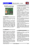
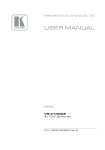
RC Switch Twin opto V3.0
User manual
09/2007
Cod. FS013001
RC Switch Twin version.
The two output must be connected in parallel with
the two sections of the existing mechanical shutter
switch; the output 1 (upper connector) is to be
connected to the first step (focus) and the output 2
(lower) to the shutter switch. If the switch (or one
section of the switch) doesn’t work at the first
attempt, simply reverse the two wires of that
section.
A pushbutton on the switch is used to enter the
programming function and for local activation of
the switch and two state leds display the state of
the Twin Switch in different working conditions.
3.
1.
Overview
Programmable functions
The switch can be programmed by the user to
adapt to different RC systems and configurations.
RC Twin Switch is a double electronic switch with
opto-coupled outputs that can be controlled by a
channel of your RC Receiver system.
It is possible to define the neutral and the active
position of each channel, without modify the setup
of your Tx.
It can be connected on a dedicated channel or it
can be used in parallel with an existing function.
The Twin Switch can be controlled by a switch,
by a pushbutton, by a stick or by a slide on the Tx,
and the user can easily select the most
convenient position to take photo (switch or stick
full up, full down, centered,…).
The ‘Twin Switch’ is a special version of the RCSwitch especially designed to control, with two
independent opto-coupled outputs, the doublestep shutter used in some photo cameras. The
two channels are controlled by the same RC
channel and can be programmed separately,
setting the two outputs activation at different
positions of the same command.
Moving the stick from 0% to 50% can activate the
first shutter step (focus and exp. time) and moving
to more than 60% will trigger the camera.
Going back to half stick travel (50%) will not
restart the focus and exposure calculation and the
camera is ready to take an other picture, while
going to 0% will restart the complete process.
2.
An additional feature called auto-on function is
also provided; some cameras have an auto shutoff function that preserves the battery life
switching off the camera after a time (from 30” to
90”) with no operation, i.e. if no pictures are taken.
To avoid that the camera will switch off during
remote operation it is possible to program the
switch to take a picture after a programmable
delay from the last command (auto-on function).
This function can be disabled if it is not required
and when it is enabled the time-out interval can be
programmed from few seconds up to 10 minutes
to adapt to different cameras. The auto-on
function starts only after the first manual
activation.
Connections
RC Twin Switch has a cable with a standard
connector that can be fitted in a free channel of
the receiver; if it must be connected in parallel
with an existing function, a Y harness adaptor is
required.
The outputs of the Twin Switch have two micro
JST connector and two separate harness with two
wires, one blue (or black) and one red: the blue
(black) one is the GND pole of the opto-coupler.
RC Twin Switch Opto instruction manual
4.
Mode Set Up
The switch has two operation modes that can be
selected each time the system is powered on:
single and continuous mode output.
In single mode the output 2 is activated for a
fixed time of approx. 0.6 seconds even if the
relative command stays in on position for a longer
time; to trigger again it is necessary to switch the
command off and then on again.
www.rc-flysoft.com
Page 1/4
RC Switch Twin opto V3.0
User manual
09/2007
Cod. FS013001
In continuous mode the output 2 will follow
exactly the command, staying active for all the
time the command is on.
The output 1 is always in continuous mode.
The selection between these two modes is done
by setting the command on the transmitter before
switching on the receiver: if the command is in on
position (for the output 2) the activation is in single
mode, while if it is in off position continuous mode
is selected.
During the normal function one led (red or green
according with the selected mode) blinks at every
2” and the red and green one turns on during
output 1 (red) and output 2 (green) activation
either by command or by internal timeout.
6.
Board identification
The mode selection is not permanently stored in
the microcontroller memory and the selection is
done every time the Twin Switch is switched on.
The selected function mode is confirmed by the
led color at power on:
State leds
Output 1
[Focus]
Servo cable
to receiver
Output 2
[Shutter]
Red means that the selected mode is single.
Program
push-button
Green means that the mode is continuous.
Note:
5.
When the single mode is selected, to
avoid false output activation, you must
release the command (stick or switch)
after power on to activate normal
operation.
Two leds, one red and one green, are used to
signal some conditions and to drive the user in the
programming procedure.
At the start-up (power on) there are four possible
conditions:
Condition
LED indication
1. Memory error or invalid
parameter stored.
Red led flashing at
high rate
2. Start of programming
procedure
Four red blinks
3. Normal function with
continuous output mode
selected
2 sec. solid green
and then flashing
green every 2 sec.
4. Normal function with
single shot output mode
selected
2 seconds solid red
and then flashing
red every 2 sec.
(see the detailed
description of the
program sequence)
RC Twin Switch Opto instruction manual
Power On mode / programming
If the system is powered on normally and the
memory contains valid data, the system starts in
normal function mode, as described in the Mode
set-up table.
State LED indication
Mode set-up table
7.
If the memory is blank or if data are not valid, the
system starts in error state: the red led is flashing
at high rate and the only way to restore the normal
condition is to restart the system in programming
mode.
Each time the system is powered with the
pushbutton pressed, the programming procedure
starts.
Note the program procedure will not start
automatically when an error is detected in
the data memory: the user must power on
the system with the pushbutton pressed.
8.
Programming procedure
To start the programming sequence, power on the
system with the pushbutton pressed.
It is now possible to program the two command
trigger positions and the auto-on function.
www.rc-flysoft.com
Page 2/4
RC Switch Twin opto V3.0
User manual
09/2007
Cod. FS013001
Command position set-up in a simple 4 steps
programming sequence for output 1:
Auto on function programming: function
enable/disable and timeout interval set-up.
This sequence starts immediately after the end of
the previous one, with the red led switched on for
5 seconds.
1
2
3
4
1 Sec.
1
2
3
4
At power on in program mode you have one
blink of the red led repeated four times;
during the blinks you have to set the
command in the neutral position [the
position in which the output 1 is not active].
When the led stops blinking the current
position is stored in microcontroller memory
and the red led stays on for 2 seconds;
when the led is solid on it is possible to
release the command.
During the green blink (repeated four times)
move the command in the active position
[the position in which output 1 is on]…
…and wait for the green led on at the end of
the data store.
1
1
2
2 Sec.
…n
2
Pressing the pushbutton while the red led is
on disables the auto-on function and
terminates the program sequence.
Otherwise, the auto-on function is enabled,
the time count starts with the green led
blinking at each 0,5” and ends when the
pushbutton is pressed.
In both cases at the end the green led turns on for
2” to indicate that data are saved in memory and
then switches off.
The same procedure is then repeated for output 2;
to identify that you are now setting the output 2,
the led blinks are now two (repeated four times)
for off and on positions.
The programming procedure is terminated and the
Twin Switch must be powered off and on again
for the new set-up to take effect.
If at the end the red led is blinking at high speed
the programming sequence has been aborted for
an error: please verify that the off and the on
commands of the same channel are not stored at
the same value, or at very close positions.
Switch off and repeat the programming procedure.
The automatic activation is always in single mode
for both output 1 and output 2; first output 1 is
activated and then, after a short delay, the output
2 is activated. After a second short delay both
outputs are switched off.
Example of programming sequence for output 2:
1
2
3
4
Led indications summary:
Red led identifies the off position
Green led identifies the on position
1 blink (four times) identifies output 1
2 blinks (four times) identify output 2
RC Twin Switch Opto instruction manual
www.rc-flysoft.com
Page 3/4
RC Switch Twin opto V3.0
User manual
09/2007
Cod. FS013001
9.
Programming examples
Case 1: you have the switch on channel 5 and
want to activate focus moving a slider from 0 to
50% and take a photo at 75%; your camera will
switch off after a 30” time interval with no
operation and you decide to program the auto-on
function to take a picture every 28”.
You
RC Twin Switch
Operation
Display
Connect the switch
on ch 5, press the
push-button and
switch on system.
Move the slider at
0% position
Move slider to
50% and hold
Move the slider at
0% position
Move slider to
75% and hold
Programming
procedure
starts
Connect the switch
on ch 5, press the
push-button and
switch on system.
Move the switch
down
Position
stored (off)
Position
stored (active)
Position
stored (off)
Green Led
on
Position
stored (active)
Release stick
Red Led
on for 5
seconds
Waiting for
time-out
enable.
Start counting 28
seconds
Green Led
flashing at
0.5”
Counting the
time
4x1 red
blinks
press the pushbutton while red
led is on
Green Led
on
Led off
Position
stored (active)
4x2 red
blinks
Position
stored (off)
4x2 green
blinks
Green Led
on
Position
stored (active)
Red Led
on for 5
seconds
Waiting for
time-out
enable.
Green Led
on
Data saved in
memory
Led off
press the pushbutton after 28”
Position
stored (off)
4x1 green
blinks
Red Led
on
Move switch in
upper position
Effect
Programming
procedure
starts
Green Led
on
Move the switch
down
4x2 green
blinks
Display
Red Led
on
Move switch in
center position
4x2 red
blinks
Red Led
on
RC Twin Switch
Operation
4x1 green
blinks
Green Led
on
You
Effect
4x1 red
blinks
Red Led
on
Case 2: you want to program the camera switch
connected on a Tx switch (3 positions) operating
on ch. 5, activating focus at middle position and
taking picture when you move the switch up; your
camera will not automatically switch off and you
don’t need the auto-on function.
Procedure
end
Data saved in
memory
Procedure
end
When you power on system with:
When you power on system with:
Stick at 0%
Green Led
on & flash
Continuous
mode selected
Switch down
Green Led
on & flash
Continuous
mode selected
Stick at 75%
Red Led on
and flash
Single shot
mode selected.
Switch up
Red Led on
& flash
Single shot
mode selected.
RC Twin Switch Opto instruction manual
www.rc-flysoft.com
Page 4/4