1
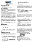
User Manual for Drum Winch SWI-TEC S-Klasse Last revised: January 08, 2015 Issued by: Marco Bachmann, Managing Director, Neveta Nautica S.L. Table of Contents Approved Use 3 Description of the SWI-TEC S-Klasse 3 1.1 Standard Features 4 2. Training 5 3. Installation 5 3.1 Selection of the location 3.2 Use of the device 5 6 Operating Instructions 8 4.1 Lifting a Person 4.2 Lowering a Person 4.3 Operation of the Brake Mechanism 8 8 8 Manufacturer’s Guidelines 9 5.1 Checking the Drum Winch Before Each Use 5.1.1 Checking the Endless Line 5.1.2 Checking the Drum Winch 9 10 10 5.2 Maintenance of the Drum Winch 10 5.3 Storage of the Drum Winch 10 5.4 Care of the Drum Winch 10 5.5 Disposal of the Drum Winch 11 Commissioning Instructions 11 Declaration of Conformity 13 1. 4. 5. 6. 2 Approved Use The SWI-TEC S-Klasse is a manually operated drum winch for lifting and lowering persons. Applied are the EN 1808:1999+A1:2010: Safety Requirements for Suspended Personnel Hoisting Equipment – Design Calculations, Stability Criteria, Construction, Tests (based on), the EG Machinery Directive 2006/42/EG and the BGR 159: Suspended Personnel Hoisting Equipment (based on). In contrast to the EN 1808:1999+A1:2010: Safety Requirements on Suspended Personnel Hoisting Equipment – Design Calculations, Stability Criteria, Construction, Tests due to type design constraints the SWI-TEC S-Klasse drum winch uses a 6 mm Polyester-Dyneema rope instead of a steel cable as a loadbearing line. The hand-operated drum winch must not be used to transport material loads. The drum winch may be used for the transport of persons only in conjunction with a second independent, tested and approved fall arresting device (e.g. guided type fall arrester or retracting lifeline) and must be attached to a separate, tested and approved anchorage point. For machinery used to lift persons, or persons and goods, where a hazard of falling from a height of more than 3 meters exists (see Annex IV, No. 17 of Directive 2006/42/EG), a conformity assessment procedure of the complete system shall be made by the manufacturer as referred to in Article 12, Paragraphs 3 or 4 of Directive 2006/42/EG. The drum winch must not be used in areas exposed to higher risks such as danger of explosions or corrosive environment. 1. Description of the SWI-TEC S-Klasse The drum winch may be used for lifting, lowering and positioning of persons. The drum winch has a Load Line which is wound on a drum. With the use of an Endless Line the Load Line can be wound onto or off the drum. In this way the person is lifted or lowered. A pawl/ratchet mechanism ensures that a person is always securely held in position at all times. The SWI-TEC S-Klasse has a Load Line guide. 3 1.1 Standard features of the SWI-TEC S-Klasse: SWI-TEC S-Klasse 13m Weight: 6.7 kg Dimensions: Ø 165 mm, L = 215 mm Approved load of 150 kg A drum roll with 6 mm Polyester-Dyneema rope Working height: 13 m Number of Load Line layers: 5 layers Two layers of rope remain on the drum at the end of downward movement. Aluminum / plastic housing Ambient temperature for operation: between -30° C and +50° C. Ambient temperature for lubricants: between -30° C and +120° C. Noise: ≤ 70 dB(A) A manual force of about 26 daN is required on the Endless Line when a maximum load of 150 kg is applied to the top rope layer. Load Line: Cover material: Polyester Core material: Dyneema Diameter: 6 mm Breaking Strength: 2.500 daN Length: 13 m Only original ropes from SWI-TEC must be used. SWI-TEC S-Klasse 22m Weight: 7.6 kg Dimensions: Ø 185 mm, L = 215 mm Approved load of 150 kg A drum roll with 6 mm Polyester-Dyneema rope Working height: 22 m Number of Load Line layers: 6 layers Two layers of rope remain on the drum at the end of downward movement. Aluminum / plastic housing Ambient temperature for operation: between -30° C and +50° C Ambient temperature for lubricants: between -30° C and +120° C Noise: ≤ 70 dB(A) A manual force of about 26 daN is required on the Endless Line when a maximum load of 150 kg is applied to the top rope layer. 4 Load Line: Cover material: Core material: Diameter: Breaking Strength: Length: Polyester Dyneema 6 mm 2.500 daN 22 m Only original ropes from SWI-TEC must be used. The lifting and lowering drive mechanism incorporates a braking system. The device is manually operated by an Endless Line which is used to wind the Load Line onto or off the drum. The Endless Line can be released at any time. The brake system in the driving mechanism prevents further movement of the Load Line. Warning The user must ensure that the Load Line is always kept under tension. A tensile force of 20 N must be maintained in order for the Load Line to be wrapped tightly onto the drum. 2. Training Requirements The original operating instructions must be accessible to the user before using the device. The user must be trained on the equipment by the operator / owner. The operator / owner of the equipment shall bear full responsibility that proper training is carried out. All original instructions, signs and labels must be observed when using this device. In addition, use only tested and approved harnesses, attachment points and connection means. Before commissioning the device, perform a visual and a functional test. 3. Installation 3.1 Site selection Before installing the device it is necessary to have carefully examined all factors that may affect the use of the drum winch and other equipment. These factors include job set up, environmental factors, location and type of workplace hazards, location and strength of the anchorage point to which the drum winch is mounted. Leave yourself enough time to consider all foreseeable possibilities. Always consult a competent person to who is familiar with the dangers and localities in the specific workplace Estimate the expected Load Line length required. Install the unit so that the Load Line and the Endless Line easily reach the lowest point of the expected work location. Consider it may need extra length if the person has to perform work offset from the vertical. The Load Line must not be crossed and but must always be able to move freely. If necessary include in the work schedule the set up of safety barriers and signage so that other equipment, materials and people do not interfere with the proper operation of the unit. 5 The device including the Load Line and the Endless Line must not pass over sharp edges or too close to objects where they might catch. Avoid mounting locations where waste, pollutants, and falling objects may impair or damage the device, Load Line and Endless Line or cause injury to people. The drum winch must be free to move at the anchorage point and must not be rigidly mounted. The Load Line must always run vertically off the drum. Sideloading of the Load Line will stress the Load Line guide and may cause it to fail. Never install the equipment where the device or lines risk exposure to electrical hazards. Note Create a work plan and a rescue plan before starting the installation. Take into consideration the original instructions and the risk assessment of the client. Caution The person operating the device must be secured against risk of falling with his/her own tested and approved restraint or fall arrest system. Also, the person must be safeguarded against falling objects. The person operating the Endless Line shall never stand between the drum winch and Load Line, since the Load Line is under tension and a broken line may snap back and possibly causing injury to people standing near the line. Never leave the appliance unattended when it is in use. 3.2 Use of the device The fixed anchorage point must have a safety factor of 10:1 for personnel, but at least be suitable for a force absorption of 7.5 kN. For the second safety, depending on the intended use, a separate solid anchorage point with a force absorption capacity of 7.5 kN must be available. The anchorage points must be tested and approved. Approved connectors must meet the forces imparted by the anchorage points. Attaching the device to crane hook is prohibited. 6 Caution A competent person must be consulted if the security of the anchorage is in question. 1. Anchorage Minimum Load Capacity: 7,5 kN 2. Anchorage Minimum Load Capacity: 7,5 kN Carabiner Connectors (EN 362) Carabiner Connectors (EN 362) Drum Winch SWI-TEC S-Klasse Guided Type Fall Arrester (EN 353-2) or Retractable Type Fall Arrester (EN 360) Carabiner Connectors (EN 362) Carabiner Connectors (EN 362) E.g. Personnel Lifting Device 7 4. Operating instructions 4.1 Lifting a person Pull on the Endless Line to raise a person. You can raise the person, with a maximum load of 150 kg on the top layer of rope, using a manual force of about 26 daN on the Endless Line. The manual force is practically the same for both the 13m and 22m version due to the different diameters of the pulley. The Endless Line must only be operated by 1 person (not two or more people at a time). Important Make sure that the Load Line is tightly and evenly wound onto the drum. 4.2 Lowering a person To lower a person, disengage the lock with a well-measured tug on the other side of the Endless Line and continue to pull evenly. The person is then lowered in a smooth motion. 4.3 Operation of the braking system The brake mechanism engages automatically, the load is securely held in any position. The weight of the attached person activates the braking system automatically. The device is blocked. During lowering (pulling on the Endless Line), the brake is disengaged, but re-engages immediately by the weight of the attached person when the pulling action is stopped. The brake engages the mechanical pawl/ratchet device. Important If the Load Line is completely wound out from the drum, all the way to the end and the Endless Line continues to be pulled on the same side, the Load Line is wound up onto the drum in the wrong direction and the brake function is overridden. The typical "clicking" sound of the pawl/ratchet mechanism is not audible in this situation. The user will notice immediately after switching the pulling action to the other side of the Endless Line that no braking effect is present and will sink back to 8 the end position of the fully wound out Load Line (the Endless Line must be pulled through a length of 2 m in order to raise the load a distance of 20 cm). When the user now continues to pull on the same side of the Endless Line, the load is again lifted, however, now the "clicking" sound of the pawl/ratchet mechanism will be audible and the braking function is active. 5. Manufacturer‘s regulations Observe all national rules and regulations of the respective country where the drum winch is used that may apply to the operation and any equipment safety standard approval requirements. Never exceed the maximum load limits specified on the data plate attached to the unit. It is strictly prohibited to alter any part or parts of the device. Never use two or more drum winches to raise and lower persons. A shift of the load could lead to only one device carrying the full weight of the load and thereby cause all devices to fail. Always load the device evenly. Do not move people abruptly, as this could induce dynamic loading forces which could exceed the maximum operating load. Always locate the winch in such a manner that when raising and lowering the Load Line is prevented from chafing. The Load Line must be able to move freely at all times. Whenever a person is to be raised, first check the unit by lifting the load a few inches to make sure that the "clicking" sound of the pawl/ratchet mechanism is audible. Check each time before using the drum winch and the Load Line for external damage. If in doubt, the device must not be used without prior repair. The drum winch may only be used in conjunction with a second independent, tested and approved fall arresting device which must be attached to a separate, tested and approved anchorage point. Only the manufacturer, or personnel approved by the manufacturer in writing, may repair the appliance, or make any repairs, exchanges, replace or add parts to the drum winch. 5.1 Inspecting the drum winch before each use Before each use, the user must check the device carefully, observe the original user instructions and all Safety-, Warning- and Caution Labels. Inspections by the user are all the more important the more adverse the environmental and workplace conditions are to which the drum winch is exposed. The drum winch must be inspected for any signs of wear, damage, alteration or missing parts. 9 5.1.1 Inspecting the Endless Line Inspect the Endless Line for signs of contamination, abrasion and cuts. Check the splice. 5.1.2 Inspecting the drum winch Check the drum winch for any signs of external damage. Should the inspections of the device show any signs damage, wear, alteration or missing parts then the unit is to be taken out of service and returned to the manufacturer or an authorized repair station. 5.2 Maintenance of the drum winch The frequency of the periodic maintenance depends on the specific environmental conditions, the conditions and frequency of use and must be carried out at intervals of 12 (twelve) months. For product liability reasons, this service has to be performed by the manufacturer or personnel approved by the manufacturer in writing. Only the manufacturer, or personnel approved by the manufacturer in writing, may repair the appliance, or make any repairs, exchanges, replace or add parts to the drum winch. After 5 years a major overhaul is to be performed by the manufacturer. 5.3 Storage of the drum winch Store it in a dry, clean room, away from heaters or steam-emitting appliances, not in direct contact with concrete or ash floors, as they can cause corrosion. The device must not be exposed to permanent UV light. During storage, the Load Line must always be fully retracted with the brake disengaged (short pulling action on the Endless Line). 5.4 Care of the drum winch The device should be cleaned with a damp cloth and dried using an absorbent cloth. Important Do not clean the unit with any chemical cleaner containing trichloroethane, thinner or cold cleaner. Do not use grease near the brake pads. 10 5.5 Disposal of the drum winch For safety reasons, the device must be discarded or replaced after ten (10) years from the date of manufacture. The manufacturer will deny any and all claims if the device continues to be used after this period. Exception If after ten (10) years a winch is still in perfect condition, the manufacturer may grant an extension of 2 (two) additional years after a thorough examination by the manufacturer. This requires, however, that the annual inspections from this point forward may only be carried out by the manufacturer! 6. Commissioning Instructions - Setup Guide for the drum winch Removal of the end cover to provide access to the Drive Pulley and explanation of the function of the pawl/ratchet bypass lever. 1. Fold the safety ring of the Safety Pin (A) and remove from the Cap Nut (B). 2. Unscrew the Cap Nut (B) and remove the End Cover (C). 3. Press the Locking Lever (black ball) (D) and pull out the desired length of the Load Line (F). 4. After releasing the Locking Lever (D) the Load Line must be pulled out with a firm tug. With this movement the pawl/ratchet mechanism is again engaged. 5. Lead the Endless Line through the Guide Rollers (E) and the slot in the End Cover (C) and place it into the groove in the drive pulley. Make sure the Endless Line is fully seated in the groove. 6. Replace the End Cover (C) together with the Guide Rollers (E). Important It is important to ensure that the slots on the End Cover (C) line up exactly with the guide pins on the device. The pin/slot positions allow this to occur in only one position so that the Locking Lever (D) is secured. Check for proper alignment if any effort is required. 7. Screw the Cap Nut (B) until the hole is aligned with the hole in the axle. 8. Insert the Safety Pin (A) and fold down the safety ring. Important Functional Check: When pulling on the Endless Line to wind the Load Line onto the drum the pawl/ratchet mechanism should emit an audible "clicking" sound 11 A Safety Pin B Cap Nut C End Cover D Locking Lever E Guide Rollers F Load Line Only the manufacturer, or personnel approved by the manufacturer in writing, may repair the appliance, or make any repairs, exchanges, replace or add parts to the drum winch. Production and Distribution Distribution – Germany SWI-TEC Neveta Nautica S.L. Lindenstrasse 9 D-78733 Rötenberg Tel.: +49 (0) 7444 95 41 920 Fax: +49 (0) 7444 95 41 921 E-mail: [email protected] www.swi-tec.com Production facility SWI-TEC Neveta Nautica S.L. Poligono 9, Apartado 51 E- 07680 Porto Cristo (Mallorca) Tel.: +34 (0) 971 82 24 26 Fax: +34 (0) 971 82 20 17 E-mail: [email protected] www.swi-tec.com 12 Declaration of Conformity: EG- Declaration of Conformity for the drum winch SWI-TEC S-Klasse Pursuant to the EG- Machinery Directive 2006/42/EG, Annex II A We hereby declare the company, SWI-TEC, Neveta Nautica S.L. Poligono 9, Apt. 51 E-07680 Porto Cristo (Mallorca) that the drum winch SWI-TEC S-Klasse for raising and lowering persons is in compliance with the following relevant directives: EG Machinery Directive 2006/42/EG Applied Harmonized Standards: EN ISO 12100:2011-03: Safety of Machinery – General Design Principles – Risk Assessment and Risk Reduction EN 1808:1999+A1:2010: Safety Requirements on Suspended Personnel Hoisting Equipment – Design Calculations, Stability Criteria, Construction, Tests (based on) Applied National Regulations: BGR 159: Suspended Personnel Hoisting Equipment (based on) Mr. Marco Bachmann (address above) is authorized to compile the technical documentation. The type design of the device has been verified by: DGUV Test, Testing and Certification Body for Lifting Equipment, Safety Components and Machinery Department of Wood and Metal, Kreuzstraße 45, 40210 Düsseldorf, Germany The DGUV-Test symbol was issued for the type design. DGUV Test-Testing Certificate Nr. HSM 15001 The unit as delivered complies with the tested type design. 13