1
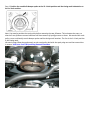
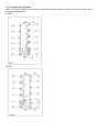
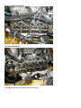
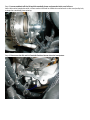
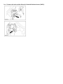
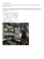
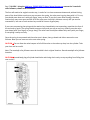
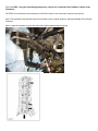
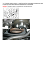
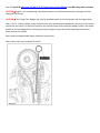
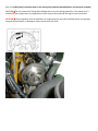
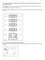
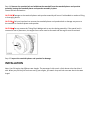
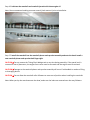
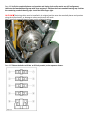
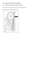
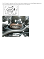
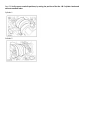
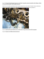
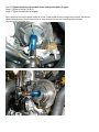
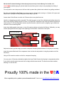
3V Ford Camshaft Installation Caution/Disclaimer This guide should be used for reference only. We do believe however, that it is 100% accurate and if you follow it step by step, you will be fine. Always refer to the click here- Ford Service Manual before starting any procedure as complex as this. Things you will need: Freedom Racing Tool & Die 3V Valve Spring Compressor and Timing Chain Locking Wedge - Do NOT attempt to do the job without these 3V specialty tools! Lint-free cloth or shop towels A very clean motor Camshafts Two new Cam Phaser Sprocket Bolts – The existing phaser bolts can NOT be reused. Cam Cover Gaskets (optional) The stock gaskets are reusable but why not replace them when about $30.00 gets them new from Ford Permatex Ultra Black Hi-Temp RTV Silicone (optional) 9/16” spark plug socket 5/16” box-end wrench or socket and ratchet 18mm box-end wrench 15mm socket and ratchet Before beginning, please read the valve spring instructions located at the bottom of this document, or just click here Let's get started… Step 1: Position the crankshaft damper spoke at the 12 o'clock position and the timing mark indentation at the 1 o'clock position. Note: You need to position the crank pulley before removing the cam followers. This orientates the cams, so that the 3 cam followers on each side have the least amount of spring pressure on them. We marked the crank pulley, so we could easily see the damper spoke and the timing mark locations. The line in the 1 o'clock position is the timing mark. We used a large 18mm box-end wrench on the crank pulley bolt with the spark plugs out and the transmission in neutral. click here- Ford TSB Spark Plug Removal Procedure Step 2: Remove the cam covers: Note: The Haynes manual has you reverse the tightening sequence when loosening the cam cover bolts. Here is the tightening sequence. RH side: LH side: Right-Hand Side (passenger’s) Left-Hand side (driver’s) STOP Plug all holes and galleys before continuing! Step 3: Loosen and back off the RH and LH camshaft phaser and sprocket bolts, one full turn: Note: We used a breaker bar with a 15mm socket. We held an 18mm box end wrench on the crank pulley bolt, to keep the crankshaft from spinning. Step 4: Disconnect the RH and LH Camshaft Position Sensor electrical connectors. Step 5: Remove the bolts and the RH and LH Camshaft Position Sensors (CMP's). Step 6: Stop and verify: Note: If the camshaft lobes are not exactly positioned as shown, the crankshaft will require one full additional rotation to 12 o'clock. Note: The No. 1 cylinder (passenger’s side, front) camshaft exhaust lobe (the middle lobe), must be coming up on the exhaust stroke. Verify by noting the position of the 2 intake camshaft lobes and the exhaust lobe on the No. 1 cylinder. Step 7: RH SIDE - Using the click here- FR-303-1039-TD Valve Spring Compressor remove the 3 camshaft roller followers, shown in the illustration. The foot will need to be angled a certain way, in order for it to have movement downward, without hitting parts of the head. Make sure that as you compress the spring, the valve stem is going along with it. If it's not, you should press down on it with your finger, every so often. If you don't press often enough, the valve retainer keys may come apart and fall off of the valve stem. Avoid this, because not only will you need to reassemble it, but one or both retainer keys could fall into an oil galley way. If you start compressing the spring and the retainer keys immediately start separating, reposition the foot of the tool and try again. The spring should compress nicely and you may or may not, need to press the valve stem down (with your finger) as you go along. The valve stem should press down fairly easily with your finger, if everything is setup correctly. Once the spring is compressed and the valve stem is down, then go ahead and either remove the cam follower. Now you can move on to the next valve spring. CAUTION Do not allow the valve keepers to fall off the valve or the valve may drop into the cylinder. Take your time and be careful. Note: The camshaft roller followers must be installed in their original locations. Record camshaft roller follower locations. CAUTION Immediately plug all cylinder head holes and timing chain cavity to stop anything from falling into your engine! Step 8: LH SIDE - Using the Valve Spring Compressor, remove the 3 camshaft roller followers, shown in the illustration. CAUTION: Do not allow the valve keepers to fall off the valve or the valve may drop into the cylinder. Note: The camshaft roller followers must be installed in their original locations. Record camshaft roller follower locations. Note: It may be necessary to push the valve down while compressing the spring. We removed the specified cam followers from the RH side, then the LH side. Be sure to keep them in order, so you can put them back in their original locations. Step 9: Rotate the crankshaft clockwise, as viewed from the front, positioning the crankshaft damper spoke at the 6 o'clock position and the timing mark indentation at the 7 o'clock position. CAUTION The crankshaft cannot be moved past the 6 o'clock position once set. Step 10: Install the click here- FR-303-1175-TD Timing Chain Locking Wedge in the RH timing chain as shown. CAUTION Engine is not freewheeling. Camshaft procedure must be followed exactly or damage to valves and pistons will result. CAUTION The Timing Chain Wedge tool must be installed square to the timing chain and the engine block. Note: This is a “locking” wedge. Using excessive force when positioning the wedge tool can result in the need to remove the front cover. To avoid this scenario, use common sense when setting the wedge in place. You should be able to lock the wedge firmly in place by placing one finger through the handle loop and pressing down firmly with just that finger. Note: Keep the wedge handle lightly oiled while being stored. Note: Engine front cover removed for clarity. Step 11: Scribe (index) a location mark on the timing chain and the camshaft phaser and sprocket assembly. CAUTION Do not remove the Timing Chain Wedge tool at any time during assembly. If the special tool is removed or out of placement, the engine front cover must be removed and the engine must be retimed. CAUTION The timing chain must be installed in its original position onto the camshaft phaser and sprocket using the scribed marks, or damage to valves and pistons will result. Step 12: Remove the bolts in the sequence shown, remove the front camshaft bearing cap, and then the remaining bearing caps. CAUTION Remove the front thrust camshaft bearing cap straight upward from the bearing towers, or the bearing cap may be damaged from sideloading. Note: The camshaft bearing caps must be installed in their original locations. Record the camshaft bearing cap locations. Step 13: Clean and inspect the RH camshaft bearing caps. The camshaft front thrust bearing cap contains an oil metering groove. Make sure the groove is free of foreign material. Step 14: Remove the sprocket bolt and withdraw the camshaft from the camshaft phaser and sprocket assembly, leaving the camshaft phaser and sprocket assembly in place. Discard the bolt and washer. CAUTION Damage to the camshaft phaser and sprocket assembly will occur if mishandled or used as a lifting or leveraging device. CAUTION Only use hand tools to remove the camshaft phaser and sprocket bolt or damage may occur to the camshaft or camshaft phaser and sprocket. CAUTION Do not remove the Timing Chain Wedge tool at any time during assembly. If the special tool is removed or out of placement, the engine front cover must be removed and the engine must be retimed. Step 15: Inspect the camshaft phaser and sprocket for damage. INSTALLATION Note: Your 3V engine has different cam lengths. The passenger’s side cam is a little shorter then the driver’s side. When you pull the first stock cam out of your engine, just match it up with the new cam that is the same length. Step 16: Lubricate the camshaft and camshaft journals with clean engine oil. Note: Some recommend soaking your new cams in fresh motor oil prior to installation. Step 17: Install the camshaft into the camshaft phaser and sprocket assembly and onto the head. Install a new camshaft phaser and sprocket bolt finger-tight. CAUTION Do not remove the Timing Chain Wedge tool at any time during assembly. If the special tool is removed or out of placement, the engine front cover must be removed and the engine must be retimed. CAUTION Damage to the camshaft phaser and sprocket assembly will occur if mishandled or used as a lifting or leveraging device. CAUTION Do not allow the camshaft roller followers to move out of position when installing the camshaft. Note: When you lay the cam down onto the head, make sure the lobes are centered over the cam followers. Step 18: Verify the camshaft phaser and sprocket and timing chain scribe marks are still in alignment. Lubricate the camshaft bearing caps with clean engine oil. Position the front camshaft bearing cap. Position the remaining camshaft bearing caps. Install the bolts finger-tight. CAUTION The timing chain must be installed in its original position onto the camshaft phaser and sprocket using the scribed marks, or damage to valves and pistons will result. Note: Install the camshaft bearing caps in their original locations. Step 19: Tighten the bolts to 10 Nm, or 89 inch pounds, in the sequence shown. Step 20: Remove the Timing Chain Locking Wedge. Step 21: Repeat steps 10-20 on the LH (driver’s side) cam. Note: For the LH side, step 10 will have you install the wedge like this: Note: Engine front cover removed for clarity. Step 22: Rotate the crankshaft a half turn counterclockwise and position the crankshaft damper spoke at the 12 o'clock position and the timing mark indentation at the 1 o'clock position. Step 23: Verify correct camshaft positions, by noting the position of the No. 1 & 5 cylinder intake and exhaust camshaft lobes. Cylinder 1 Cylinder 5 Step 24: Using the Valve Spring Compressor, install the 6 originally removed camshaft roller followers. Make sure you put them back in their original locations. Note: For us, all of the cam followers went in easily except for one; the number 8 cylinder exhaust. We had to rotate the crank pulley counter clock wise, until enough room opened up to slip the follower in. Step 25: Install the RH and LH CMP sensors and the bolts. Torque these bolts to 89 inch pounds. Step 26: Connect the CMP electrical connectors. Step 27: Tighten the RH and LH, camshaft phaser and sprocket bolt in 2 stages: Stage 1: Tighten to 40 Nm (30 lb-ft). Stage 2: Tighten an additional 90 degrees. Note: We drew lines on the phaser and also on the 15mm socket we were using to turn the bolt. We held an 18mm box-end wrench on the crank pulley in order to keep the cam and crankshaft from spinning. Here are before and after pics: Step 28: Install your cam covers. Step 29: Make sure all connectors that were removed during engine prep, are reconnected. Step 30: Reinstall battery tray and battery if it was removed for the RH cam cover removal. Cam install complete! Special Thanks to hammeron and Jason Bane! FR-303-1039-TD (Patent Pending) 3V Valve Spring Compressor by Freedom Racing Tool and Die, LLC: CAUTION Immediately plug all cylinder head holes and timing chain cavity to stop anything from falling in your engine! You may wish to use a shop towel or lint-free cloth to protect the cylinder head surface from getting scratched. Be patient and practice a few times on an easy-to-get-to cylinder before moving on. Cylinder # 4 is open and easy to see. If you get in a hurry the project is less likely to go well. Loosen lower Guide Screw to unlock unit. Remove shoe cover plate from ram. Hook the J-shaped leg around the camshaft. The other leg goes on top of the cylinder head surface where the valve cover sets #8 Cylinder exhaust is easier if you start with compressor body under the brake fluid tank and rotate upward. F-150 and Expedition owners may find it easier to jack the motor up slightly to get a little more clearance from the steering shaft. Insert shoe tightly against valve stem, on top of the spring retainer and under the follower. Optionally, you may use the spring removal shoe (larger inner opening) on the retainer. Install shoe cover plate. Shoe Cover Plate ▼ Shoe 5/16 Hex Guide Screws Set screw Adjust set screw to get the range you need to compress the spring proper distance for the job you are doing Insert the center-drilled end of the compressor shoe into the slot and position it using the pointed end of the Set Screw Using a 5/16 wrench or socket on the Hex, compress the spring You may use a 1/8 hex key (included) to tighten the lower Guide Screw to hold spring in compressed position. If you wish to use the upper screw as a lock, simply switch screws around. The lower screw has a washer, allowing it to lock the ram. Proudly 100% made in the U A Have a specialty tool or product you need manufactured? Contact us at [email protected]