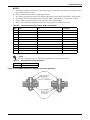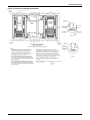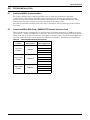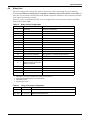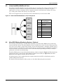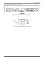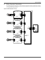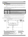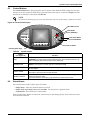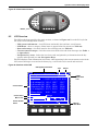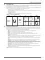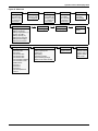
1
AC Power
For Business-Critical Continuity™
Liebert® APM™
User Manual–15-90kVA, 120 and 208V, 50/60Hz
TABLE OF CONTENTS
IMPORTANT SAFETY INSTRUCTIONS . . . . . . . . . . . . . . . . . . . . . . . . . . . . . . . . . . . . . . . . . . . . . . . .1
GLOSSARY OF SYMBOLS . . . . . . . . . . . . . . . . . . . . . . . . . . . . . . . . . . . . . . . . . . . . . . . . . . . . . . . .4
1.0
INSTALLATION . . . . . . . . . . . . . . . . . . . . . . . . . . . . . . . . . . . . . . . . . . . . . . . . . . . . . . . . . .5
1.1
Initial Inspections. . . . . . . . . . . . . . . . . . . . . . . . . . . . . . . . . . . . . . . . . . . . . . . . . . . . . . . . . . . . 6
1.1.1
Storing for Delayed Installation . . . . . . . . . . . . . . . . . . . . . . . . . . . . . . . . . . . . . . . . . . . . . . . . . 6
1.2
Preliminary Checks . . . . . . . . . . . . . . . . . . . . . . . . . . . . . . . . . . . . . . . . . . . . . . . . . . . . . . . . . . 6
1.3
UPS Location . . . . . . . . . . . . . . . . . . . . . . . . . . . . . . . . . . . . . . . . . . . . . . . . . . . . . . . . . . . . . . . 6
1.2.1
1.3.1
1.3.2
Identification. . . . . . . . . . . . . . . . . . . . . . . . . . . . . . . . . . . . . . . . . . . . . . . . . . . . . . . . . . . . . . . . . 6
Positioning the UPS . . . . . . . . . . . . . . . . . . . . . . . . . . . . . . . . . . . . . . . . . . . . . . . . . . . . . . . . . . . 6
Environmental Considerations . . . . . . . . . . . . . . . . . . . . . . . . . . . . . . . . . . . . . . . . . . . . . . . . . . 7
1.4
Considerations in Moving the Liebert APM . . . . . . . . . . . . . . . . . . . . . . . . . . . . . . . . . . . . . . . 7
1.5
Mechanical Considerations . . . . . . . . . . . . . . . . . . . . . . . . . . . . . . . . . . . . . . . . . . . . . . . . . . . . 8
1.5.1
1.5.2
1.5.3
1.6
Clearances. . . . . . . . . . . . . . . . . . . . . . . . . . . . . . . . . . . . . . . . . . . . . . . . . . . . . . . . . . . . . . . . . . . 8
Floor Installation . . . . . . . . . . . . . . . . . . . . . . . . . . . . . . . . . . . . . . . . . . . . . . . . . . . . . . . . . . . . . 8
Cable Entry . . . . . . . . . . . . . . . . . . . . . . . . . . . . . . . . . . . . . . . . . . . . . . . . . . . . . . . . . . . . . . . . . . 8
45kVA and 90kVA UPS Frames—Auxiliary Cabinets. . . . . . . . . . . . . . . . . . . . . . . . . . . . . . . 9
1.6.1
Optional Cabinets. . . . . . . . . . . . . . . . . . . . . . . . . . . . . . . . . . . . . . . . . . . . . . . . . . . . . . . . . . . . . 9
1.7
Optional Seismic Brackets . . . . . . . . . . . . . . . . . . . . . . . . . . . . . . . . . . . . . . . . . . . . . . . . . . . . 10
1.8
Liebert FlexPower™ Assembly . . . . . . . . . . . . . . . . . . . . . . . . . . . . . . . . . . . . . . . . . . . . . . . . 10
1.9
Static Bypass Assembly . . . . . . . . . . . . . . . . . . . . . . . . . . . . . . . . . . . . . . . . . . . . . . . . . . . . . . 11
2.0
ELECTRICAL CONNECTIONS—UPS . . . . . . . . . . . . . . . . . . . . . . . . . . . . . . . . . . . . . . . . . .12
2.1
Power Cabling. . . . . . . . . . . . . . . . . . . . . . . . . . . . . . . . . . . . . . . . . . . . . . . . . . . . . . . . . . . . . . 12
2.2
External Protective Devices. . . . . . . . . . . . . . . . . . . . . . . . . . . . . . . . . . . . . . . . . . . . . . . . . . . 12
2.1.1
2.2.1
2.2.2
2.2.3
2.2.4
2.2.5
2.2.6
2.2.7
2.2.8
2.2.9
2.2.10
2.3
Rectifier and Bypass Input Supply of the UPS. . . . . . . . . . . . . . . . . . . . . . . . . . . . . . . . . . . . .
External Battery. . . . . . . . . . . . . . . . . . . . . . . . . . . . . . . . . . . . . . . . . . . . . . . . . . . . . . . . . . . . .
UPS Output . . . . . . . . . . . . . . . . . . . . . . . . . . . . . . . . . . . . . . . . . . . . . . . . . . . . . . . . . . . . . . . .
UPS Input Configuration . . . . . . . . . . . . . . . . . . . . . . . . . . . . . . . . . . . . . . . . . . . . . . . . . . . . . .
Cabling Guidelines . . . . . . . . . . . . . . . . . . . . . . . . . . . . . . . . . . . . . . . . . . . . . . . . . . . . . . . . . . .
Cable Connections . . . . . . . . . . . . . . . . . . . . . . . . . . . . . . . . . . . . . . . . . . . . . . . . . . . . . . . . . . .
Accessory Fuses and Backfeed Breaker Wiring . . . . . . . . . . . . . . . . . . . . . . . . . . . . . . . . . . . .
Safety Ground . . . . . . . . . . . . . . . . . . . . . . . . . . . . . . . . . . . . . . . . . . . . . . . . . . . . . . . . . . . . . . .
Protective Devices. . . . . . . . . . . . . . . . . . . . . . . . . . . . . . . . . . . . . . . . . . . . . . . . . . . . . . . . . . . .
Cabling Procedure . . . . . . . . . . . . . . . . . . . . . . . . . . . . . . . . . . . . . . . . . . . . . . . . . . . . . . . . . . .
13
13
13
14
15
16
20
21
21
22
Control Cables Details . . . . . . . . . . . . . . . . . . . . . . . . . . . . . . . . . . . . . . . . . . . . . . . . . . . . . . . 23
2.3.1
2.4
Cable Rating . . . . . . . . . . . . . . . . . . . . . . . . . . . . . . . . . . . . . . . . . . . . . . . . . . . . . . . . . . . . . . . . 12
Static Bypass Assembly Features . . . . . . . . . . . . . . . . . . . . . . . . . . . . . . . . . . . . . . . . . . . . . . . 23
Dry Contacts . . . . . . . . . . . . . . . . . . . . . . . . . . . . . . . . . . . . . . . . . . . . . . . . . . . . . . . . . . . . . . . 25
2.4.1
2.4.2
2.4.3
2.4.4
2.4.5
Input Dry Contacts. . . . . . . . . . . . . . . . . . . . . . . . . . . . . . . . . . . . . . . . . . . . . . . . . . . . . . . . . . .
Output Dry Contacts . . . . . . . . . . . . . . . . . . . . . . . . . . . . . . . . . . . . . . . . . . . . . . . . . . . . . . . . .
Liebert BDC Interface . . . . . . . . . . . . . . . . . . . . . . . . . . . . . . . . . . . . . . . . . . . . . . . . . . . . . . . .
Battery Cabinet Interface Connectors. . . . . . . . . . . . . . . . . . . . . . . . . . . . . . . . . . . . . . . . . . . .
EPO Input—Optional . . . . . . . . . . . . . . . . . . . . . . . . . . . . . . . . . . . . . . . . . . . . . . . . . . . . . . . . .
i
25
26
26
27
28
3.0
BATTERY INSTALLATION . . . . . . . . . . . . . . . . . . . . . . . . . . . . . . . . . . . . . . . . . . . . . . . . . . 29
3.1
Introduction . . . . . . . . . . . . . . . . . . . . . . . . . . . . . . . . . . . . . . . . . . . . . . . . . . . . . . . . . . . . . . . 29
3.2
Safety . . . . . . . . . . . . . . . . . . . . . . . . . . . . . . . . . . . . . . . . . . . . . . . . . . . . . . . . . . . . . . . . . . . . 29
3.3
UPS Batteries—Liebert APM 45kVA Frame Only. . . . . . . . . . . . . . . . . . . . . . . . . . . . . . . . . 30
3.4
External Battery Cabinet Installation . . . . . . . . . . . . . . . . . . . . . . . . . . . . . . . . . . . . . . . . . . 30
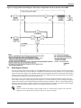
3.4.1
3.4.2
3.4.3
3.4.4
Matching Battery Cabinets . . . . . . . . . . . . . . . . . . . . . . . . . . . . . . . . . . . . . . . . . . . . . . . . . . . .
Connecting the Batteries . . . . . . . . . . . . . . . . . . . . . . . . . . . . . . . . . . . . . . . . . . . . . . . . . . . . . .
Installation Considerations . . . . . . . . . . . . . . . . . . . . . . . . . . . . . . . . . . . . . . . . . . . . . . . . . . . .
Connecting the Battery Cabinet to the UPS . . . . . . . . . . . . . . . . . . . . . . . . . . . . . . . . . . . . . . .
30
31
33
33
3.5
Battery Ground Fault Detection Set . . . . . . . . . . . . . . . . . . . . . . . . . . . . . . . . . . . . . . . . . . . . 35
3.6
Non-Standard Batteries . . . . . . . . . . . . . . . . . . . . . . . . . . . . . . . . . . . . . . . . . . . . . . . . . . . . . . 35
4.0
LIEBERT BDC . . . . . . . . . . . . . . . . . . . . . . . . . . . . . . . . . . . . . . . . . . . . . . . . . . . . . . . . . 36
4.1
Normal (UPS) Mode . . . . . . . . . . . . . . . . . . . . . . . . . . . . . . . . . . . . . . . . . . . . . . . . . . . . . . . . . 36
4.2
Maintenance Mode . . . . . . . . . . . . . . . . . . . . . . . . . . . . . . . . . . . . . . . . . . . . . . . . . . . . . . . . . . 37
4.3
Locating the Cabinet . . . . . . . . . . . . . . . . . . . . . . . . . . . . . . . . . . . . . . . . . . . . . . . . . . . . . . . . 37
4.4
Cable Installation . . . . . . . . . . . . . . . . . . . . . . . . . . . . . . . . . . . . . . . . . . . . . . . . . . . . . . . . . . . 37
4.1.1
4.4.1
4.4.2
4.4.3
Bypass Mode . . . . . . . . . . . . . . . . . . . . . . . . . . . . . . . . . . . . . . . . . . . . . . . . . . . . . . . . . . . . . . . . 36
Wiring Preparation. . . . . . . . . . . . . . . . . . . . . . . . . . . . . . . . . . . . . . . . . . . . . . . . . . . . . . . . . . . 37
Power Cable Installation . . . . . . . . . . . . . . . . . . . . . . . . . . . . . . . . . . . . . . . . . . . . . . . . . . . . . . 37
Input/Output Wiring . . . . . . . . . . . . . . . . . . . . . . . . . . . . . . . . . . . . . . . . . . . . . . . . . . . . . . . . . 38
4.5
Bolting Cabinets Together . . . . . . . . . . . . . . . . . . . . . . . . . . . . . . . . . . . . . . . . . . . . . . . . . . . . 40
5.0
INSTALLATION DRAWINGS . . . . . . . . . . . . . . . . . . . . . . . . . . . . . . . . . . . . . . . . . . . . . . . . .41
6.0
OPTION INSTALLATION . . . . . . . . . . . . . . . . . . . . . . . . . . . . . . . . . . . . . . . . . . . . . . . . . . . 52
6.1
Liebert IntelliSlot Communication . . . . . . . . . . . . . . . . . . . . . . . . . . . . . . . . . . . . . . . . . . . . . 52
6.2
Liebert IntelliSlot Web Card—SNMP/HTTP Network Interface Card . . . . . . . . . . . . . . . . . 52
6.3
Web Card—Optional . . . . . . . . . . . . . . . . . . . . . . . . . . . . . . . . . . . . . . . . . . . . . . . . . . . . . . . . 53
6.4
Relay Card . . . . . . . . . . . . . . . . . . . . . . . . . . . . . . . . . . . . . . . . . . . . . . . . . . . . . . . . . . . . . . . . 54
6.5
Liebert IntelliSlot MultiPort 4 Card . . . . . . . . . . . . . . . . . . . . . . . . . . . . . . . . . . . . . . . . . . . . 55
6.6
Alber BDSi Battery Monitoring System—Optional . . . . . . . . . . . . . . . . . . . . . . . . . . . . . . . . 55
6.7
Battery Temperature Compensation. . . . . . . . . . . . . . . . . . . . . . . . . . . . . . . . . . . . . . . . . . . . 57
7.0
OPERATION . . . . . . . . . . . . . . . . . . . . . . . . . . . . . . . . . . . . . . . . . . . . . . . . . . . . . . . . . . .58
7.1
Static Bypass Switch . . . . . . . . . . . . . . . . . . . . . . . . . . . . . . . . . . . . . . . . . . . . . . . . . . . . . . . . 59
7.2
Operating Modes . . . . . . . . . . . . . . . . . . . . . . . . . . . . . . . . . . . . . . . . . . . . . . . . . . . . . . . . . . . 60
8.0
OPERATOR CONTROL AND DISPLAY PANEL . . . . . . . . . . . . . . . . . . . . . . . . . . . . . . . . . . . 61
8.1
Operator Control Panel . . . . . . . . . . . . . . . . . . . . . . . . . . . . . . . . . . . . . . . . . . . . . . . . . . . . . . 61
8.2
Mimic Display Indicators . . . . . . . . . . . . . . . . . . . . . . . . . . . . . . . . . . . . . . . . . . . . . . . . . . . . . 62
8.3
Control Buttons . . . . . . . . . . . . . . . . . . . . . . . . . . . . . . . . . . . . . . . . . . . . . . . . . . . . . . . . . . . . 63
8.4
Alarm Buzzer . . . . . . . . . . . . . . . . . . . . . . . . . . . . . . . . . . . . . . . . . . . . . . . . . . . . . . . . . . . . . . 63
8.5
LCD Overview . . . . . . . . . . . . . . . . . . . . . . . . . . . . . . . . . . . . . . . . . . . . . . . . . . . . . . . . . . . . . 64
8.6
Navigation Keys . . . . . . . . . . . . . . . . . . . . . . . . . . . . . . . . . . . . . . . . . . . . . . . . . . . . . . . . . . . . 65
8.7
LCD Menus and Data Items . . . . . . . . . . . . . . . . . . . . . . . . . . . . . . . . . . . . . . . . . . . . . . . . . . 65
8.8
Language Selection . . . . . . . . . . . . . . . . . . . . . . . . . . . . . . . . . . . . . . . . . . . . . . . . . . . . . . . . . 67
ii
8.9
Current Date and Time . . . . . . . . . . . . . . . . . . . . . . . . . . . . . . . . . . . . . . . . . . . . . . . . . . . . . . 67
8.10
UPS History Log. . . . . . . . . . . . . . . . . . . . . . . . . . . . . . . . . . . . . . . . . . . . . . . . . . . . . . . . . . . . 68
8.11
Types of LCD Screens . . . . . . . . . . . . . . . . . . . . . . . . . . . . . . . . . . . . . . . . . . . . . . . . . . . . . . . 69
8.11.1
8.11.2
8.11.3
8.11.4
8.12
Opening Display . . . . . . . . . . . . . . . . . . . . . . . . . . . . . . . . . . . . . . . . . . . . . . . . . . . . . . . . . . . . .
Default Screen . . . . . . . . . . . . . . . . . . . . . . . . . . . . . . . . . . . . . . . . . . . . . . . . . . . . . . . . . . . . . .
UPS Help Screen . . . . . . . . . . . . . . . . . . . . . . . . . . . . . . . . . . . . . . . . . . . . . . . . . . . . . . . . . . . .
Screen Saver Window. . . . . . . . . . . . . . . . . . . . . . . . . . . . . . . . . . . . . . . . . . . . . . . . . . . . . . . . .
69
69
70
70
Pop-Up Windows . . . . . . . . . . . . . . . . . . . . . . . . . . . . . . . . . . . . . . . . . . . . . . . . . . . . . . . . . . . 70
8.12.1
8.12.2
8.12.3
8.12.4
8.12.5
8.12.6
8.12.7
From Bypass to Inverter Mode With Power Interruption . . . . . . . . . . . . . . . . . . . . . . . . . . . .
From Inverter to Bypass Mode With Interruption . . . . . . . . . . . . . . . . . . . . . . . . . . . . . . . . . .
System Self-Test . . . . . . . . . . . . . . . . . . . . . . . . . . . . . . . . . . . . . . . . . . . . . . . . . . . . . . . . . . . . .
Battery Capacity Test Confirmation . . . . . . . . . . . . . . . . . . . . . . . . . . . . . . . . . . . . . . . . . . . . .
Battery Self-Test Aborted, Condition Not Met . . . . . . . . . . . . . . . . . . . . . . . . . . . . . . . . . . . . .
Battery Refresh Charge Aborted, Condition Not Met . . . . . . . . . . . . . . . . . . . . . . . . . . . . . . .
Enter Control Password . . . . . . . . . . . . . . . . . . . . . . . . . . . . . . . . . . . . . . . . . . . . . . . . . . . . . . .
70
70
71
71
71
71
71
9.0
OPERATION . . . . . . . . . . . . . . . . . . . . . . . . . . . . . . . . . . . . . . . . . . . . . . . . . . . . . . . . . . .74
9.1
Liebert APM Operating Modes . . . . . . . . . . . . . . . . . . . . . . . . . . . . . . . . . . . . . . . . . . . . . . . . 74
9.2
UPS Startup . . . . . . . . . . . . . . . . . . . . . . . . . . . . . . . . . . . . . . . . . . . . . . . . . . . . . . . . . . . . . . . 74
9.2.1
9.2.2
Startup Procedure . . . . . . . . . . . . . . . . . . . . . . . . . . . . . . . . . . . . . . . . . . . . . . . . . . . . . . . . . . . 75
Switching Between UPS Operation Modes . . . . . . . . . . . . . . . . . . . . . . . . . . . . . . . . . . . . . . . . 76
9.3
UPS Battery Start . . . . . . . . . . . . . . . . . . . . . . . . . . . . . . . . . . . . . . . . . . . . . . . . . . . . . . . . . . 76
9.4
Switching the UPS from Normal Operation to Maintenance Bypass . . . . . . . . . . . . . . . . . . 77
9.5
Switching the UPS from Maintenance Bypass to Normal Operation . . . . . . . . . . . . . . . . . . 78
9.6
Powering Down the UPS . . . . . . . . . . . . . . . . . . . . . . . . . . . . . . . . . . . . . . . . . . . . . . . . . . . . . 79
9.7
Emergency Shutdown With EPO . . . . . . . . . . . . . . . . . . . . . . . . . . . . . . . . . . . . . . . . . . . . . . 80
9.8
Auto Restart . . . . . . . . . . . . . . . . . . . . . . . . . . . . . . . . . . . . . . . . . . . . . . . . . . . . . . . . . . . . . . . 80
9.9
Reset After Shutdown for Emergency Stop (EPO Action) or Other Conditions . . . . . . . . . . 80
9.10
Battery Protection . . . . . . . . . . . . . . . . . . . . . . . . . . . . . . . . . . . . . . . . . . . . . . . . . . . . . . . . . . 80
9.10.1 Battery Undervoltage Pre-Warning . . . . . . . . . . . . . . . . . . . . . . . . . . . . . . . . . . . . . . . . . . . . . 80
9.10.2 Battery End-of-Discharge (EOD) Protection. . . . . . . . . . . . . . . . . . . . . . . . . . . . . . . . . . . . . . . 80
9.11
Replacing Dust Filters . . . . . . . . . . . . . . . . . . . . . . . . . . . . . . . . . . . . . . . . . . . . . . . . . . . . . . . 81
10.0
SPECIFICATIONS AND TECHNICAL DATA. . . . . . . . . . . . . . . . . . . . . . . . . . . . . . . . . . . . . . . 82
10.1
Conformity and Standards. . . . . . . . . . . . . . . . . . . . . . . . . . . . . . . . . . . . . . . . . . . . . . . . . . . . 82
10.2
UPS Environmental . . . . . . . . . . . . . . . . . . . . . . . . . . . . . . . . . . . . . . . . . . . . . . . . . . . . . . . . . 82
10.3
Batteries Approved for Use in Liebert APM Systems . . . . . . . . . . . . . . . . . . . . . . . . . . . . . . 83
10.4
UPS Electrical Characteristics . . . . . . . . . . . . . . . . . . . . . . . . . . . . . . . . . . . . . . . . . . . . . . . . 83
APPENDIX A - HAZARDOUS SUBSTANCES OR ELEMENTS ANNOUNCEMENT . . . . . . . . . . . . . . . . A88
APPENDIX B - UPS STATUS MESSAGES . . . . . . . . . . . . . . . . . . . . . . . . . . . . . . . . . . . . . . . . . A89
iii
FIGURES
Figure 1
Figure 2
Figure 3
Figure 4
Figure 5
Figure 6
Figure 7
Figure 8
Figure 9
Figure 10
Figure 11
Figure 12
Figure 13
Figure 14
Figure 15
Figure 16
Figure 17
Figure 18
Figure 19
Figure 20
Figure 21
Figure 22
Figure 23
Figure 24
Figure 25
Figure 26
Figure 27
Figure 28
Figure 29
Figure 30
Figure 31
Figure 32
Figure 33
Figure 34
Figure 35
Figure 36
Figure 37
Figure 38
Figure 39
Figure 40
Figure 41
Figure 42
Figure 43
Figure 44
Figure 45
Figure 46
Figure 47
Figure 48
Figure 49
Cabinet arrangement . . . . . . . . . . . . . . . . . . . . . . . . . . . . . . . . . . . . . . . . . . . . . . . . . . . . . . . . . . . . . 9
Liebert FlexPower assembly indicators and controls . . . . . . . . . . . . . . . . . . . . . . . . . . . . . . . . . . . 10
Static bypass assembly connections. . . . . . . . . . . . . . . . . . . . . . . . . . . . . . . . . . . . . . . . . . . . . . . . . 11
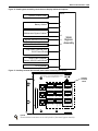
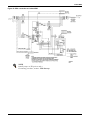
Single UPS block diagram—dual input configuration . . . . . . . . . . . . . . . . . . . . . . . . . . . . . . . . . . 14
Input busbars—Liebert APM 45kVA frame . . . . . . . . . . . . . . . . . . . . . . . . . . . . . . . . . . . . . . . . . . 16
Input busbars—Liebert APM 90kVA frame . . . . . . . . . . . . . . . . . . . . . . . . . . . . . . . . . . . . . . . . . . 17
Busbars—Liebert BDC . . . . . . . . . . . . . . . . . . . . . . . . . . . . . . . . . . . . . . . . . . . . . . . . . . . . . . . . . . . 18
Busbars—External Battery Cabinet . . . . . . . . . . . . . . . . . . . . . . . . . . . . . . . . . . . . . . . . . . . . . . . . 19
Accessory fuses . . . . . . . . . . . . . . . . . . . . . . . . . . . . . . . . . . . . . . . . . . . . . . . . . . . . . . . . . . . . . . . . . 20
Backfeed breaker wiring when bypass distribution cabinet not used . . . . . . . . . . . . . . . . . . . . . . 20
Ground and neutral busbar connections . . . . . . . . . . . . . . . . . . . . . . . . . . . . . . . . . . . . . . . . . . . . . 21
Static bypass assembly connections to display cabinet and options . . . . . . . . . . . . . . . . . . . . . . . 24
Auxiliary terminal block detail (static switch assembly front panel) . . . . . . . . . . . . . . . . . . . . . . 24
Input dry contacts . . . . . . . . . . . . . . . . . . . . . . . . . . . . . . . . . . . . . . . . . . . . . . . . . . . . . . . . . . . . . . . 25
Output dry contacts and EPO wiring . . . . . . . . . . . . . . . . . . . . . . . . . . . . . . . . . . . . . . . . . . . . . . . 26
EPO wiring and signal names for J6 . . . . . . . . . . . . . . . . . . . . . . . . . . . . . . . . . . . . . . . . . . . . . . . . 28
Battery cabinet, 600mm wide—details . . . . . . . . . . . . . . . . . . . . . . . . . . . . . . . . . . . . . . . . . . . . . . 31
Battery trays for 600mm wide battery cabinet . . . . . . . . . . . . . . . . . . . . . . . . . . . . . . . . . . . . . . . . 32
Battery cabinet connection to Liebert APM . . . . . . . . . . . . . . . . . . . . . . . . . . . . . . . . . . . . . . . . . . 34
Wiring of battery ground fault detection set . . . . . . . . . . . . . . . . . . . . . . . . . . . . . . . . . . . . . . . . . . 35
Single UPS with external Liebert BDC—typical configuration . . . . . . . . . . . . . . . . . . . . . . . . . . . 36
Liebert BDC—access plate removed . . . . . . . . . . . . . . . . . . . . . . . . . . . . . . . . . . . . . . . . . . . . . . . . 37
BDC connection to Liebert APM . . . . . . . . . . . . . . . . . . . . . . . . . . . . . . . . . . . . . . . . . . . . . . . . . . . 39
Bolting Liebert APM to a Liebert BDC . . . . . . . . . . . . . . . . . . . . . . . . . . . . . . . . . . . . . . . . . . . . . . 40
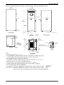
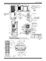
UPS dimensions- front view . . . . . . . . . . . . . . . . . . . . . . . . . . . . . . . . . . . . . . . . . . . . . . . . . . . . . . . 41
Lineup arrangement, Liebert APM with battery and Liebert BDCs . . . . . . . . . . . . . . . . . . . . . . . 41
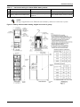
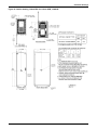
UPS dimensions continued, center of gravity—side, top and bottom views . . . . . . . . . . . . . . . . . 42
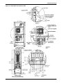
UPS main components—typical unit . . . . . . . . . . . . . . . . . . . . . . . . . . . . . . . . . . . . . . . . . . . . . . . . 44
UPS cable connections—45kVA and 90kVA frames . . . . . . . . . . . . . . . . . . . . . . . . . . . . . . . . . . . . 45
Battery cabinet connection to UPS . . . . . . . . . . . . . . . . . . . . . . . . . . . . . . . . . . . . . . . . . . . . . . . . . 46
Battery cabinet outline drawing, weights and center of gravity . . . . . . . . . . . . . . . . . . . . . . . . . . 47
Outline drawing, Liebert BDC for Liebert APM, 15-90kVA . . . . . . . . . . . . . . . . . . . . . . . . . . . . . 48
Liebert BDC connection to UPS . . . . . . . . . . . . . . . . . . . . . . . . . . . . . . . . . . . . . . . . . . . . . . . . . . . . 49
Acceptable hardware configuration for torque application. . . . . . . . . . . . . . . . . . . . . . . . . . . . . . . 50
Seismic mounting bracket details . . . . . . . . . . . . . . . . . . . . . . . . . . . . . . . . . . . . . . . . . . . . . . . . . . 51
Liebert IntelliSlot Web card display . . . . . . . . . . . . . . . . . . . . . . . . . . . . . . . . . . . . . . . . . . . . . . . . 53
Liebert IntelliSlot MultiPort 4 card pin assignment . . . . . . . . . . . . . . . . . . . . . . . . . . . . . . . . . . . 55
Alber BDSi controller and input connection . . . . . . . . . . . . . . . . . . . . . . . . . . . . . . . . . . . . . . . . . . 56
Multi-temperature sensors . . . . . . . . . . . . . . . . . . . . . . . . . . . . . . . . . . . . . . . . . . . . . . . . . . . . . . . . 57
Single module block diagram—Single input configuration with three-breaker Liebert BDC . . . 58
Single module block diagram—Dual input configuration with three-breaker Liebert BDC . . . . 59
Overview of control panel . . . . . . . . . . . . . . . . . . . . . . . . . . . . . . . . . . . . . . . . . . . . . . . . . . . . . . . . 61
Mimic display indicators location. . . . . . . . . . . . . . . . . . . . . . . . . . . . . . . . . . . . . . . . . . . . . . . . . . . 62
Control button layout . . . . . . . . . . . . . . . . . . . . . . . . . . . . . . . . . . . . . . . . . . . . . . . . . . . . . . . . . . . . 63
Alarm buzzer location . . . . . . . . . . . . . . . . . . . . . . . . . . . . . . . . . . . . . . . . . . . . . . . . . . . . . . . . . . . . 64
Sections of the LCD. . . . . . . . . . . . . . . . . . . . . . . . . . . . . . . . . . . . . . . . . . . . . . . . . . . . . . . . . . . . . . 64
Menu tree . . . . . . . . . . . . . . . . . . . . . . . . . . . . . . . . . . . . . . . . . . . . . . . . . . . . . . . . . . . . . . . . . . . . . 66
Language selection screen . . . . . . . . . . . . . . . . . . . . . . . . . . . . . . . . . . . . . . . . . . . . . . . . . . . . . . . . 67
Date and time screen . . . . . . . . . . . . . . . . . . . . . . . . . . . . . . . . . . . . . . . . . . . . . . . . . . . . . . . . . . . . 68
iv
Figure 50
Figure 51
Figure 52
Figure 53
Figure 54
Figure 55
Figure 56
Figure 57
History log records . . . . . . . . . . . . . . . . . . . . . . . . . . . . . . . . . . . . . . . . . . . . . . . . . . . . . . . . . . . . . .
Opening display. . . . . . . . . . . . . . . . . . . . . . . . . . . . . . . . . . . . . . . . . . . . . . . . . . . . . . . . . . . . . . . . .
Default screen . . . . . . . . . . . . . . . . . . . . . . . . . . . . . . . . . . . . . . . . . . . . . . . . . . . . . . . . . . . . . . . . . .
Screen saver window. . . . . . . . . . . . . . . . . . . . . . . . . . . . . . . . . . . . . . . . . . . . . . . . . . . . . . . . . . . . .
Battery start button location . . . . . . . . . . . . . . . . . . . . . . . . . . . . . . . . . . . . . . . . . . . . . . . . . . . . . .
Typical configuration for single UPS with external Liebert BDC . . . . . . . . . . . . . . . . . . . . . . . . .
Dust filter replacement. . . . . . . . . . . . . . . . . . . . . . . . . . . . . . . . . . . . . . . . . . . . . . . . . . . . . . . . . . .
Battery, circuit breaker and UPS wiring with external batteries with four connecting
wires. . . . . . . . . . . . . . . . . . . . . . . . . . . . . . . . . . . . . . . . . . . . . . . . . . . . . . . . . . . . . . . . . . . . . . . . . .
Figure 58 Battery, circuit breaker and UPS wiring with external batteries with three connecting
wires. . . . . . . . . . . . . . . . . . . . . . . . . . . . . . . . . . . . . . . . . . . . . . . . . . . . . . . . . . . . . . . . . . . . . . . . . .
v
68
69
69
70
76
79
81
87
87
TABLES
Table 1
Table 2
Table 3
Table 4
Table 5
Table 6
Table 7
Table 8
Table 9
Table 10
Table 11
Table 12
Table 13
Table 14
Table 15
Table 16
Table 17
Table 18
Table 19
Table 20
Table 21
Table 22
Table 23
Table 24
Table 25
Table 26
Table 27
Table 28
Table 29
Table 30
Table 31
Table 32
Table 33
Table 34
Table 35
Table 36
Table 37
Table 38
Table 39
Table 40
Table 41
Table 42
Table 43
Table 44
LED indications. . . . . . . . . . . . . . . . . . . . . . . . . . . . . . . . . . . . . . . . . . . . . . . . . . . . . . . . . . . . . . . . .
Description of dry contact input port . . . . . . . . . . . . . . . . . . . . . . . . . . . . . . . . . . . . . . . . . . . . . . . .
Output dry contact relays . . . . . . . . . . . . . . . . . . . . . . . . . . . . . . . . . . . . . . . . . . . . . . . . . . . . . . . . .
Liebert BDC interface. . . . . . . . . . . . . . . . . . . . . . . . . . . . . . . . . . . . . . . . . . . . . . . . . . . . . . . . . . . .
Battery cabinet interface . . . . . . . . . . . . . . . . . . . . . . . . . . . . . . . . . . . . . . . . . . . . . . . . . . . . . . . . .
EPO input contact relays . . . . . . . . . . . . . . . . . . . . . . . . . . . . . . . . . . . . . . . . . . . . . . . . . . . . . . . . .
Control wiring for Liebert APM to battery cabinet. . . . . . . . . . . . . . . . . . . . . . . . . . . . . . . . . . . . .
Control wiring for Liebert APM UPS to Liebert BDC . . . . . . . . . . . . . . . . . . . . . . . . . . . . . . . . . .
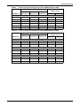
Center of gravity and weights for Liebert APM 90 kVA frame UPS . . . . . . . . . . . . . . . . . . . . . . .
Center of gravity and weights for Liebert APM 45 kVA frame UPS . . . . . . . . . . . . . . . . . . . . . . .
Interconnect wiring for Liebert APM to battery cabinet . . . . . . . . . . . . . . . . . . . . . . . . . . . . . . . .
Interconnect wiring for Liebert APM to Liebert BDC . . . . . . . . . . . . . . . . . . . . . . . . . . . . . . . . . .
Spring washer torque application . . . . . . . . . . . . . . . . . . . . . . . . . . . . . . . . . . . . . . . . . . . . . . . . . .
Liebert APM communication options. . . . . . . . . . . . . . . . . . . . . . . . . . . . . . . . . . . . . . . . . . . . . . . .
Relay Card pin configuration . . . . . . . . . . . . . . . . . . . . . . . . . . . . . . . . . . . . . . . . . . . . . . . . . . . . . .
Relay card jumper configuration. . . . . . . . . . . . . . . . . . . . . . . . . . . . . . . . . . . . . . . . . . . . . . . . . . .
UPS operating modes . . . . . . . . . . . . . . . . . . . . . . . . . . . . . . . . . . . . . . . . . . . . . . . . . . . . . . . . . . . .
Descriptions of UPS operator control and display panel . . . . . . . . . . . . . . . . . . . . . . . . . . . . . . . .
Mimic display status indicators . . . . . . . . . . . . . . . . . . . . . . . . . . . . . . . . . . . . . . . . . . . . . . . . . . . .
Control buttons . . . . . . . . . . . . . . . . . . . . . . . . . . . . . . . . . . . . . . . . . . . . . . . . . . . . . . . . . . . . . . . . .
Icons for navigation keys . . . . . . . . . . . . . . . . . . . . . . . . . . . . . . . . . . . . . . . . . . . . . . . . . . . . . . . . .
UPS menus and data window items . . . . . . . . . . . . . . . . . . . . . . . . . . . . . . . . . . . . . . . . . . . . . . . .
UPS operating modes . . . . . . . . . . . . . . . . . . . . . . . . . . . . . . . . . . . . . . . . . . . . . . . . . . . . . . . . . . . .
Mimic indicators after initialization . . . . . . . . . . . . . . . . . . . . . . . . . . . . . . . . . . . . . . . . . . . . . . . .
Mimic indicators for normal mode operation with battery breaker open . . . . . . . . . . . . . . . . . . .
Mimic indicators for normal mode operation with battery breaker closed . . . . . . . . . . . . . . . . . .
Environmental requirements . . . . . . . . . . . . . . . . . . . . . . . . . . . . . . . . . . . . . . . . . . . . . . . . . . . . . .
UPS mechanical characteristics. . . . . . . . . . . . . . . . . . . . . . . . . . . . . . . . . . . . . . . . . . . . . . . . . . . .
Liebert BDC mechanical characteristics . . . . . . . . . . . . . . . . . . . . . . . . . . . . . . . . . . . . . . . . . . . . .
Batteries approved for use in External Battery Cabinet, 600mm . . . . . . . . . . . . . . . . . . . . . . . . .
Internal batteries approved for use with 45kVA frame Liebert APM . . . . . . . . . . . . . . . . . . . . . .
UPS currents and terminals—Input (for single input unit 208V operation). . . . . . . . . . . . . . . . .
Battery cabinet mechanical characteristics. . . . . . . . . . . . . . . . . . . . . . . . . . . . . . . . . . . . . . . . . . .
UPS currents and terminals—Input (for dual input unit only 208V operation) . . . . . . . . . . . . . .
UPS currents and terminals—Bypass input (for dual input units 208V operation). . . . . . . . . . .
UPS currents and terminals—Output 208V) . . . . . . . . . . . . . . . . . . . . . . . . . . . . . . . . . . . . . . . . .
UPS currents and terminals—Battery ( 288V string) . . . . . . . . . . . . . . . . . . . . . . . . . . . . . . . . . .
AC/AC efficiency, loss and air exchange . . . . . . . . . . . . . . . . . . . . . . . . . . . . . . . . . . . . . . . . . . . . .
Rectifier input . . . . . . . . . . . . . . . . . . . . . . . . . . . . . . . . . . . . . . . . . . . . . . . . . . . . . . . . . . . . . . . . . .
Battery DC intermediate circuit . . . . . . . . . . . . . . . . . . . . . . . . . . . . . . . . . . . . . . . . . . . . . . . . . . .
Inverter output to critical load . . . . . . . . . . . . . . . . . . . . . . . . . . . . . . . . . . . . . . . . . . . . . . . . . . . . .
Bypass input . . . . . . . . . . . . . . . . . . . . . . . . . . . . . . . . . . . . . . . . . . . . . . . . . . . . . . . . . . . . . . . . . . .
Hazardous substances or elements . . . . . . . . . . . . . . . . . . . . . . . . . . . . . . . . . . . . . . . . . . . . . . . . .
UPS status messages . . . . . . . . . . . . . . . . . . . . . . . . . . . . . . . . . . . . . . . . . . . . . . . . . . . . . . . . . . . .
vi
10
25
26
26
27
28
34
38
43
43
47
50
50
52
54
54
58
61
62
63
65
72
74
75
75
75
82
82
82
83
83
83
83
84
84
84
84
85
85
85
86
86
88
89
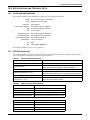
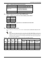
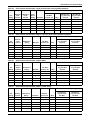
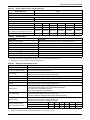
IMPORTANT SAFETY INSTRUCTIONS
SAVE THESE INSTRUCTIONS
This manual contains important instructions that should be followed during installation of the
Liebert APM, Liebert Bypass Distribution Cabinet and batteries (where applicable).
Read this manual thoroughly, paying special attention to the sections that apply to your installation,
before working with the UPS. Retain this manual for use by installing personnel.
A properly trained and qualified electrical contractor should oversee the installation of the
equipment.
The Liebert APM cannot be put into operation until it is commissioned by the manufacturer or
authorized engineer. Otherwise, human safety may be endangered and damage to the UPS will not be
covered by the warranty.
The Liebert APM is designed for commercial and industrial uses and cannot be used as life support
equipment.
!
WARNING
Exercise extreme care when handling UPS cabinets to avoid equipment damage or injury to
personnel. The Liebert APM’s weight ranges from 1100 to 2750 lb. (500 to 1250kg).
Determine unit weight and locate center of gravity symbols before handling the UPS.
Test lift and balance the cabinet before transporting it. Never tilt equipment more
than 15 degrees from vertical.
Battery manufacturers supply details of the necessary precautions to be observed when
working on, or in the vicinity of, a large bank of battery cells. These precautions should be
followed at all times.
Follow all battery safety precautions when installing, charging or servicing batteries. In
addition to the hazard of electric shock, gas produced by batteries can be explosive and
sulfuric acid can cause severe burns. When connected, the nominal battery voltage is 288VDC
and is potentially lethal.
In case of fire involving electrical equipment, use only carbon dioxide fire extinguishers or
those approved for use in fighting electrical fires.
Extreme caution is required when performing maintenance.
Be constantly aware that the UPS system contains high DC as well as AC voltages.
Check for voltage with both AC and DC voltmeters prior to making contact.
!
WARNING
As with other types of high power equipment, dangerous voltages are present within the UPS
and battery enclosure even after input power has been disconnected. The risk of contact with
these voltages is minimized as the live component parts are housed behind a metal panel.
Further internal safety screens make the equipment protected to IP20 standards. Never
remove panels or covers or open doors that will expose internal components to contact.
Read and follow all warnings, cautions and safety and operating instructions to avoid serious
injury or death from electric shock. No risk exists to any personnel when operating the
equipment in the normal manner, following the recommended operating procedures.
All equipment maintenance and servicing procedures involve internal access and should be
carried out only by trained personnel.
!
WARNING
High ground leakage current: Ground connection is essential before connecting the input
supply.
This equipment must be grounded in accordance with local electrical codes.
Maximum load must not exceed that shown on the UPS rating label.
1
!
WARNING
The Liebert APM has a control signal available for use with an automatic device, externally
located, to protect against backfeeding voltage through the mains static bypass circuit. If this
protection is not used with the switchgear that is used to isolate the bypass circuit, a label
must be added to the switchgear to advise service personnel that the circuit is connected to a
UPS system.
The text must convey the following meaning or is equivalent to: Isolate the UPS before
working on the circuit of this UPS.
Ground Leakage Currents
!
CAUTION
High Leakage Current
EARTH CONNECTION IS ESSENTIAL BEFORE CONNECTING THE INPUT SUPPLY.
Earth leakage current exceeds 3.5 mA and is less than 1000 mA.
Transient and steady-state earth leakage currents, which may occur when starting the
equipment, should be taken into account when selecting instantaneous RCCB or RCD devices.
Residual Current Circuit Breakers (RCCBs) must be selected sensitive to DC unidirectional
pulses (Class A) and insensitive to transient current pulses.
Note also that the earth leakage currents of the load will be carried by this RCCB or RCD.
This equipment must be earthed in accordance with the local electrical code of practice.
!
WARNING
Under typical operation and with all UPS doors closed, only normal safety precautions are
necessary. The area around the UPS system should be kept free of puddles of water, excess
moisture and debris.
Special safety precautions are required for procedures involving handling, installation and
maintenance of the UPS system and the internal batteries (internal batteries accommodated
by 45kVA frame only). Observe all safety precautions in this manual before handling or
installing the UPS system as well as during all maintenance procedures. Observe all battery
safety precautions before working on or near the battery.
This equipment contains several circuits that are energized with high voltage. Only
test equipment designed for troubleshooting should be used. This is particularly true for
oscilloscopes. Always check with AC and DC voltmeters to ensure safety before making
contact or using tools. Even when the power is turned Off, dangerously high electric charges
may exist within the UPS.
All power and control wiring should be installed by a qualified electrician. All power
and control wiring must comply with the NEC and applicable local codes.
ONLY qualified service personnel should perform maintenance on the UPS system.
When performing maintenance with any part of the equipment under power, service
personnel and test equipment should be standing on rubber mats. The service personnel
should wear insulating shoes for isolation from direct contact with the floor (earth ground).
Never work alone, even if all power is removed from the equipment. A second person should
be standing by to assist and summon help in case an accident should occur.
!
CAUTION
This unit complies with the limits for a Class A digital device, pursuant to Part 15 Subpart J
of the FCC rules. These limits provide reasonable protection against harmful interference in a
commercial environment. This unit generates, uses and radiates radio frequency energy and,
if not installed and used in accordance with this instruction manual, may cause harmful
interference to radio communications. This unit is not designed for use in a residential area.
Operation of this unit in a residential area may cause harmful interference that the user must
correct at his own expense.
2
Battery Cabinet Precautions
The following warning applies to all battery cabinets supplied with UPS systems. Additional warnings and cautions applicable to battery cabinets may be found in 3.0 - Battery Installation.
!
WARNING
Internal battery strapping must be verified by manufacturer prior to moving a battery cabinet
(after initial installation).
• Battery cabinets contain non-spillable batteries.
• Keep units upright.
• Do not stack.
• Do not tilt.
Failure to heed this warning could result in smoke, fire or electric hazard.
Call 1-800-LIEBERT before moving battery cabinets (after initial installation).
Battery Hazards
!
WARNING
Special care should be taken when working with the batteries associated with this equipment.
Batteries are always live. Battery terminal voltage will exceed 300VDC and is potentially
lethal.
In addition to the hazard of electric shock, gas produced by batteries can be explosive and
sulfuric acid can eause severe burns.
Batteries should be installed, serviced and replaced only by properly trained and qualified
service personnel trained in safe battery handling methods and who have the correct PPE
(Personal Protection Equipment) and tools.
The following precautions should be observed when working with the batteries:
•
•
•
•
•
•
•
•
•
•
Eye protection should be worn to prevent injury from electrical arcs.
Remove rings, watches and all other metal objects.
Use only tools with insulated handles.
Wear rubber gloves and boots.
When replacing batteries, replace them with the same type and number of batteries or battery packs.
Do not dispose of batteries in a fire. The batteries may explode.
Do not open or mutilate batteries. Released electrolyte is harmful to the skin and eyes. It is
toxic.
Never lay metal objects of any type on top of the batteries.
Disconnect the charging source before connecting or disconnecting battery terminals.
Determine whether the battery is grounded. If the battery is grounded, remove source of
the ground. Contact with any part of a grounded battery can result in electrical shock. The
likelihood of such shock can be reduced if such grounds are removed during installation and
maintenance
If a battery leaks electrolyte, or is otherwise physically damaged, it must be replaced, stored in a container resistant to sulfuric acid and disposed of in accordance with local regulations.
If electrolyte comes into contact with skin, the affected area should be washed immediately with large
amounts of water.
3
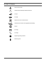
GLOSSARY OF SYMBOLS
Risk of electrical shock
!
Indicates caution followed by important instructions
AC input
AC output
i
-
Requests the user to consult the manual
+
Indicates the unit contains a valve-regulated lead acid battery
PbH2SO4
R
Recycle
DC voltage
AC voltage
Equipment grounding conductor
Bonded to ground
4
Installation
1.0
INSTALLATION
The Liebert APM is a transformerless, hardware-scalable, online UPS with 208/120V input and
208/120V output capability. The Liebert APM can operate with either a 50 or 60Hz input and provide
a matching output. The rack-mounted 15kVA/kW modules allow the UPS to scale it capacity by
15kVA increments from 15kVA to a maximum of 90kVA in a single cabinet.
The Liebert APM provides continuous, high-quality AC power to business-critical equipment, such as
telecommunications and data processing equipment. The Liebert APM supplies power free of the disturbances and variations in voltage and frequency common to utility power, which is subject to
brownouts, blackouts, surges and sags.
The Liebert APM utilizes the latest in high-frequency, double-conversion pulse width modulation
(PWM) technology and fully digital controls to enhance its reliability and increase the ease of use.
Two frame sizes are available: 45kVA/kW and 90kVA/kW. The 45kVA/kW frame is designed to accept
internal batteries; the 90kVA/kW frame does not.
This section describes the Liebert APM’s environmental requirements and mechanical considerations
that must be taken into account when planning the positioning and cabling of the UPS equipment.
Because each site is unique, this section presents a guide to general procedures and practices that
should be observed by the installing engineer, rather than step-by-step installation instructions.
!
WARNING
Do not apply electrical power to the UPS equipment before the commissioning engineer
arrives at the installation site.
The UPS must be installed by a properly trained and qualified engineer in accordance with
the information contained in this chapter. All the equipment not referred to in this manual is
shipped with details of its own mechanical and electrical installation information.
!
WARNING
Special care should be taken when working with the batteries associated with this equipment.
When connected together, the nominal battery voltage is 288VDC and is potentially lethal.
• Eye protection should be worn to prevent injury from accidental electrical arcs.
• Remove rings, watches and all metal objects.
• Only use tools with insulated handles.
• Wear rubber gloves.
If a battery leaks electrolyte or is otherwise physically damaged, it must be replaced, stored in
a container resistant to sulfuric acid and disposed of in accordance with local regulations.
If electrolyte comes into contact with skin, the affected area should be washed immediately
with large amounts of water.
NOTE
Three-phase, four-wire input power is required.
NOTE
Input power must be supplied to the Liebert APM from a properly grounded Wye or Delta
source. The Liebert APM is not for use with impedance grounded systems, corner-grounded
systems or high-leg Delta systems. For these applications, an isolation transformer must be
installed between the input power and the Liebert APM.
5
Installation
1.1
Initial Inspections
1. While the Liebert APM and ancillary cabinets are still on the truck, inspect the equipment and
shipping container for any signs of damage or mishandling. Do not attempt to install the system if
damage is apparent. If any damage is noted, file a damage claim with the shipping agency
immediately and contact Emerson Network Power Liebert Services at 1-800-LIEBERT to inform
them of the damage claim and the condition of the equipment.
2. Compare the contents of the shipment with the bill of lading. Report any missing items to the
carrier and your local Emerson representative immediately.
3. Check the product label on the back of front door and confirm the contents match the UPS model,
capacity and main parameters that were ordered.
1.1.1
Storing for Delayed Installation
If the equipment will not be installed immediately, it must be stored indoors where the humidity is no
higher than 90% and the temperature is no higher than 104°F (40°C). The storage area must protect
the Liebert APM from excessive moisture (see 10.2 - UPS Environmental).
!
!
CAUTION
If the UPS must remain disconnected from power for more than six (6) months, the batteries
(if so equipped) must be recharged before use. To charge the batteries, the unit must be
connected to utility power and started up—the charger operates only while the Liebert APM
is operating.
CAUTION
When batteries are installed in the UPS or are cabinet-mounted adjacent to the UPS, the
battery—not the UPS—dictates the designed maximum ambient temperature.
1.2
Preliminary Checks
1.2.1
Identification
The equipment supplied has an identification tag on the back of the main door listing the type and
size of the UPS.
1.3
UPS Location
1.3.1
Positioning the UPS
Choose a location for the UPS that offers:
•
•
•
•
•
•
•
Easy connection to inputs, outputs and auxiliary equipment
Enough space to service the UPS
Air circulation sufficient to expel heat produced by UPS
Protection against moisture and excessive humidity
Protection against dust and other particulate matter
Compliance with fire prevention regulations and practices
Operating environment temperature of 74-80°F (23-27°C) for maximum battery efficiency
6
Installation
1.3.2
Environmental Considerations
Before installing the Liebert APM, verify that the UPS room satisfies the environmental conditions
stipulated in 10.2 - UPS Environmental, paying particular attention to the ambient temperature
and air exchange system.
The UPS unit should be installed in a cool, dry, clean-air environment with adequate ventilation to
keep the ambient temperature within the specified operating range 32°F to 104°F (0°C to 40°C).
For optimal UPS and battery system performance and service life, maintain the operating temperature within the range of 74-80°F, (23-27°C).
The Liebert APM is cooled by internal fans. Cooling air enters the unit through the front of the unit
and is exhausted out the back. To permit proper air flow and prevent overheating, do NOT block or
cover the ventilation openings or blow air down onto the unit. The UPS requires 24 in. (610mm) ventilation clearance above the unit and 12" (305mm) behind the UPS.
See Table 38 for details on heat dissipation.
Battery Location
Temperature is a major factor in determining battery life and capacity. Battery manufacturers recommend an operating temperature of 77°F (25°C). Ambient temperatures warmer than this reduce battery life; temperatures below this reduces battery capacity. In a typical installation, battery
temperature should be maintained between 74°F and 80°F (23-27°C). Batteries should be placed
where there are no main heat sources or air inlets to prevent portions of batteries from being either
much warmer or much cooler than other parts of the batteries.
1.4
Considerations in Moving the Liebert APM
Ensure that the UPS weight is within the designated surface weight loading (lb./ft2 or kg/cm2) of any
handling equipment. See Table 28 for weights of various units.
The Liebert APM may be rolled on its casters for short distances only. For longer distances, move the
UPS with a forklift or similar equipment to ease the relocation and to reduce vibration.
The optional battery cabinets should be moved with a forklift or similar equipment.
!
WARNING
Ensure that any equipment that will be used to move the Liebert APM has sufficient lifting
capacity. The Liebert APM’s weight ranges from 1100 to 2750lb. (500 to 1250kg). See
Table 28 for details.
The UPS presents a tipping hazard. Do not tilt the Liebert APM more than 15 degrees from
vertical.
The UPS is fitted with casters—Take care to prevent movement when unbolting the
equipment from its shipping pallet. Ensure adequate personnel and lifting equipment are
available when taking the Liebert APM off its shipping pallet.
!
WARNING
The casters are strong enough for movement across even surfaces only. Casters may fail if
they are subjected to shock loading, such as being dropped or rolled over holes in the floor or
obstructions. Such failure may cause the unit to tip over, injuring personnel and damaging
the equipment.
Care must be taken when maneuvering units fitted with batteries. Keep such moves to a
minimum. For further information, see Battery Cabinet Precautions on page 3.
Final Positioning
When the equipment has been finally positioned, ensure that the adjustable stops are set so that the
UPS will remain stationary and stable (see 5.0 - Installation Drawings).
The Liebert APM and its auxiliary cabinets must be installed on a concrete or equivalent, non-resilient floor.
7
Installation
1.5
Mechanical Considerations
The Liebert APM is constructed with a steel frame and removable panels. Top and side panels are
secured to the chassis by screws. The doors may be opened for access to power connections bars, auxiliary terminals blocks and power switches.
The UPS comes with an operator control panel that provides basic operational status and alarm information. The cabinet houses both the power components and the internal batteries. Cooling is provided by internal fans. The unit sits on four casters. Adjustable stops are provided to prevent the UPS
from moving once it has been moved to its final position.
!
WARNING
The Liebert BDC and battery cabinets must be properly prepared and secured for lifting.
Improper lifting may cause the cabinets to fall, causing personal injury or death and
equipment damage.
Emerson recommends lifting the units with one of the following methods:
• Installing four eyebolts in the factory-fabricated holes, one at each corner of the unit,
attaching cables or similar strapping to the eyebolts and lifting with a suitable mechanism.
• Placing suitable straps on the Liebert BDC or battery cabinet. The straps must go under
the unit to be lifted.
1.5.1
Clearances
There are no ventilation grilles on the sides of the UPS. The sides must be accessible during installation. After installation, the unit must have a clearance of 12 in. (305mm) in the rear to permit adequate circulation of air exhausted from the UPS.
To enable routine tightening of power terminations within the UPS, make sure there is sufficient
clearance in front of the Liebert APM to permit free passage of personnel with the door fully opened.
Leave a minimum of 24 in. (610mm) between the top of the UPS and the ceiling to permit adequate
air circulation above the unit. Emerson recommends against using air conditioning or other systems
that blow air onto the top of the unit.
1.5.2
Floor Installation
If the Liebert APM, Liebert BDC or battery cabinet is to be placed on a raised floor, the UPS should be
mounted on a pedestal that will support the equipment point loading. Refer to the bottom view in
Figures 27, 31 or 32 to design this pedestal.
1.5.3
Cable Entry
Cables can enter the Liebert APM, Liebert BDC and battery cabinets from the top or bottom through
removable metal plates.
Some plates have factory-punched holes and others are designed to allow the personnel to punch
holes for fitting and securing the conduit. Once the conduit holes are punched, these plates should be
reattached to the UPS. The conduit size and wiring method must be in accordance with all local,
regional and national codes and regulations, including NEC ANSI/NFPA 70.
The UPS must be accessible from the right side to allow personnel to complete the cable connections
and make necessary adjustments. After installation is complete, the Liebert APM may be serviced
from the front.
NOTE
When installing the UPS, the customer must provide a disconnect with overcurrent protection
at the output of the UPS.
8
Installation
1.6
45kVA and 90kVA UPS Frames—Auxiliary Cabinets
The 45kVA frame consists of a single cabinet housing the UPS components and the internal battery
string. The 90kVA frame, also a single cabinet, does not accommodate internal batteries.
Optional battery cabinets are available for each Liebert APM model to provide extended run time.
Each battery cabinet houses additional strings of batteries that operate in parallel with the Liebert
APM’s internal batteries (45kVA frame only). The battery cabinets are designed to be bolted to the
left side of the UPS (see Figure 1). Refer to 3.4 - External Battery Cabinet Installation for
details.
Optional Liebert BDCs are available. These cabinets house the components necessary to provide an
external wraparound maintenance bypass switch for servicing the UPS
Liebert BDCs are designed to be bolted to the right side of the UPS (see Figure 1). Refer to 4.3 Locating the Cabinet for further details.
System Composition
A UPS system can comprise a number of equipment cabinets, depending on the system design
requirements—e.g., UPS cabinet, External Battery Cabinet and External Bypass Cabinet. In general,
all cabinets used will be the same height and are designed to be positioned side-by-side to form an
aesthetically appealing equipment suite.
1.6.1
Optional Cabinets
If the Liebert APM installation includes a Liebert BDC, the UPS must be positioned to allow the Liebert BDC to be bolted to right side of the Liebert APM (see Figure 1).
The Liebert BDC must be cabled and bolted to the Liebert APM before the UPS and bypass cabinet
are moved into their final position. Connect the input wiring to the Liebert BDC ONLY after the units
are connected and positioned.
Battery cabinets may be bolted only to the left side of the Liebert APM; see Figure 1.
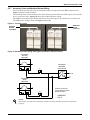
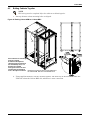
Figure 1
Cabinet arrangement
ALL UNITS VIEWED FROM ABOVE
Liebert
APM
Liebert
APM
Maintenance
Bypass
Cabinet
Battery
Cabinet
Liebert APM connected
only to Liebert BDC
(BDC must be on right side of the
Liebert APM)
Liebert APM connected to Battery Cabinet
(Battery Cabinets may be on either side
of the Liebert APM)
Liebert
APM
Battery
Cabinet
Battery
Cabinet
Maintenance
Bypass
Cabinet
Liebert APM connected to Liebert BDC and Battery Cabinets
(BDC must be on right side of the Liebert APM)
(Battery Cabinets must be on the left side of the Liebert APM
in this configuration)
9
Installation
1.7
Optional Seismic Brackets
Optional seismic mounting brackets to anchor the Liebert APM, Liebert BDC and battery cabinet to
the floor are available. Refer to Figure 35 for mounting details.
1.8
Liebert FlexPower™ Assembly
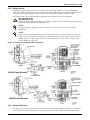
Figure 2
Liebert FlexPower assembly indicators and controls
Run LED
Fault LED
DIP Switches
Battery sta rt button
Ready Switch
The Battery start button allows starting of UPS on battery; refer to 9.3 - UPS Battery Start.
The Run LED is illuminated Green when the Liebert FlexPower assembly is operating normally.
The Fault LED will illuminate red when the Liebert FlexPower assembly has a problem.
Table 1
LED indications
LED Status
Indication
Green LED
Flashing
The inverter is starting, but has no output yet
Constant Green
The inverter has started to supply power.
OFF
The inverter has not started up.
Red LED
Constant Red
Auxiliary power failure (15V or 24V), rectifier overtemperature, rectifier failure (including battery
SCR short circuit), battery converter failure, soft start failure, main circuit back feed, abnormal
input current, inverter failure, output short circuit, bypass SCR short circuit fault, inverter relay
short circuit fault, abnormal bus voltage under non-sleep mode, module not ready, module ID
out of range and duplicated module ID.
Flashing
Charger failure, abnormal main circuit voltage, abnormal main circuit frequency, main circuit
undervoltage, main circuit reverse phase, battery unavailable, reverse battery, input zero-loss,
current sharing failure, module overload, inverter relay disconnection fault, bypass SCR
disconnection fault and input fuse blown.
OFF
No above failures or alarms.
10
Installation
1.9
Static Bypass Assembly
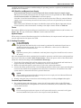
Figure 3
Static bypass assembly connections
J5
J4
J6
J7
J9
J8
J12
J10
J11
Monitor
RS-485
RS-232
Liebert IntelliSlot
Bays 1, 2, 3
The Static bypass assembly has three Liebert IntelliSlot interface card bays and connections for ancillary cabinets (Liebert BDC and battery) and for options.
11
Electrical Connections—UPS
2.0
ELECTRICAL CONNECTIONS—UPS
The UPS requires both power and control cabling once it has been mechanically installed. All control
cables must run separate from power cables in metal conduits or metal ducts that are electrically
bonded to the metalwork of the cabinets to which they are connected.
!
WARNING
Before connecting input power to the Liebert APM, ensure that you are aware of the location
and operation of the overcurrent protection devices that connect the UPS input/bypass supply
to the power distribution panel.
De-energize and lockout or tagout all incoming high- and low-voltage power circuits before
installing cables or making any electrical connections.
2.1
Power Cabling
2.1.1
Cable Rating
The main factors affecting the choice and size of cable are voltage, current (also taking into account
overcurrent), room temperature and conditions of installation of the cable. Refer to ANSI/NFPA 70.
The power cables of the system must be sized with respect to the following description:
• UPS input cables - The UPS input cables must be sized for the maximum input current, including the maximum battery recharge current, given in Table 33, with respect to the unit rating and
the input AC voltage.
• UPS bypass and output cables - The bypass and output cables must be sized for the nominal
output current, given in Table 33, with respect to the unit rating and the output AC voltage.
• Battery cables - Each UPS unit has its own internal batteries factory-wired. If connecting an
external battery cabinet, the battery cables must be sized for the battery discharge current at the
end-of-discharge voltage, as given in Table 33, with respect to the unit rating.
NOTE
Table 33 gives nominal currents for determining the size of UPS power cables. Other
important factors to consider include cable route length and coordination with protective
devices.
The power cables can be sized to suit the UPS unit rating according to Table 33.
Lug Size and Torque Requirements
Refer to Table 33 for lug size and torque requirements and to Table 13 and Figure 34.
2.2
External Protective Devices
For safety concerns, it is necessary to install external circuit breakers or other protective devices for
the input AC supply of the UPS system. This section provides generic practical information for qualified installation engineers. The installation engineers should be knowledgeable about regulatory wiring standards and the equipment to be installed.
To reduce the risk of fire, connect only to a circuit provided with branch circuit overcurrent protection
in accordance with NEC ANSI/NFPA 70.
12
Electrical Connections—UPS
2.2.1
Rectifier and Bypass Input Supply of the UPS
Overcurrents
Install suitable protective devices in the distribution unit of the incoming mains supply, considering
the power cable current-carrying capacity and overload capacity of the system. Generally, the magnetic circuit breaker with IEC60947-2 tripping curve C (normal) at the 125% of the nominal current
listed in Tables 33, 34 and 35 is recommended.
Split bypass: In case a split bypass is used, separate protective devices should be installed for the rectifier input and bypass input in the incoming mains distribution panel.
NOTE
The rectifier input and bypass input must use the same neutral line.
For an IT power network system, a 4-pole protective device must be installed on the external
input distribution and external output distribution of the UPS.
Earth Leakage, RCD Devices
Any residual current detector (RCD) installed upstream of the UPS input supply:
• Must be sensitive to DC unidirectional pulses (Class A)
• Must be insensitive to transient current pulses, and
• Must have an average sensitivity, adjustable between 0.3 and 1A.
To avoid false alarms, earth leakage monitoring devices when used in systems with split bypass input
or when used in paralleled UPS configurations, must be located upstream of the common neutral
sinking point. Alternatively, the device must monitor the combined four-wire rectifier and split
bypass input currents.
The residual earth current introduced by the RFI suppression filter inside the UPS is greater than
3.5mA and less than 300mA. Liebert recommends verifying the selectivity with all other differential
devices both upstream of the input distribution board and downstream (toward the load).
2.2.2
External Battery
The DC-compatible circuit breaker provides overcurrent protection for UPS system and battery,
which is provided by the external battery cabinet.
2.2.3
UPS Output
If an external distribution panel is used for load distribution, the selection of protective devices must
provide discrimination with those that are used at the input to the UPS (see Table 39).
13
Electrical Connections—UPS
2.2.4
UPS Input Configuration
By default, the Liebert APM ships with internal links installed between the bypass input and main
(rectifier) input (single input configuration see Figure 40).
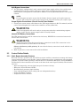
Figure 4 shows the Liebert APM in a split bypass (single source dual-input) configuration. In this
configuration the static bypass and the maintenance bypass lines are supplied by the same source
using separate feeds. Both feeds must be protected externally with properly sized protective devices.
To wire the Liebert APM as a single source dual-input UPS, remove the links and wire the bypass
feed to the bypass busbars, then wire the main feed to the main busbars (see Figure 6).
Figure 4
Single UPS block diagram—dual input configuration
14
Electrical Connections—UPS
2.2.5
Cabling Guidelines
The following are guidelines only and are superseded by local regulations and codes of practice where
applicable. Use wiring rated at 75°C or greater.
1. Take special care when determining the size of the neutral cable, as current circulating on the
neutral cable may be greater than nominal current in the case of non-linear loads. Refer to the
values in 10.4 - UPS Electrical Characteristics.
2. The ground conductor should be sized according to such factors as the fault rating, cable lengths
and type of protection. The ground cable connecting the UPS to the main ground system must
follow the most direct route possible. Control wiring and power wiring must be run in separate
conduit. Output and input cables must be run in separate conduit.
3. Consider using paralleled smaller cables for heavy currents—this can ease installation.
4. When sizing battery cables, a maximum voltage drop of 4VDC is permissible at the current
ratings in Table 37. For terminal connection sizing, see Tables 33 through 37.
5. In most installations, the load equipment is connected to a distribution network of individually
protected busbars fed by the UPS output, rather than connected directly to the UPS itself. When
this is the case, the UPS output cables can be rated to suit the individual distribution network
demands rather than being fully load-rated.
NOTE
If more load is added to the distribution panel, the unit’s cabling must be resized.
6. When laying power cables, do not form coils; this will help avoid increasing formation of
electromagnetic interference.
NOTE
Right-side access may be required when making power connections. Cable connections should
be made before a cabinet is attached to the right side of the Liebert APM or before the UPS is
placed where another obstruction, such as a wall, is against the Liebert APM’s the right side.
15
Electrical Connections—UPS
2.2.6
Cable Connections
The rectifier input, bypass output and battery are easily accessible from the right side of the unit for
installation. All require lug type terminations. They are connected to busbars on the right side of the
Liebert APM, as shown in Figures 5 and 6. These busbars are accessible when the right side panel is
removed.
!
Figure 5
WARNING
When wiring a single-input only system, connect only the power wiring to the input busbars.
Input busbars—Liebert APM 45kVA frame
16
Electrical Connections—UPS
Figure 6
Input busbars—Liebert APM 90kVA frame
17
Electrical Connections—UPS
Figure 7
Busbars—Liebert BDC
18
Electrical Connections—UPS
Figure 8
Busbars—External Battery Cabinet
19
Electrical Connections—UPS
2.2.7
Accessory Fuses and Backfeed Breaker Wiring
Two fuse blocks provide power for the backfeed breakers (standard) and the BDSi (optional). See
Figure 9 for fuse holder locations.
The backfeed breaker fuse block provides 120V nominal provided from the UPS output (L-N) and the
fuse is rated for 8 amps. Figure 10 shows the backfeed breaker wiring.
The BDSi fuse block provides 208V nominal from the UPS output (L-L) and the fuse is rated at 8A.
The BDSi power wiring is shown in Figures 19 and 38.
Figure 9
Accessory fuses
BDSi Fuse
Block
(optional)
Backfeed
Breaker
Fuse Block
Figure 10 Backfeed breaker wiring when bypass distribution cabinet not used
UPSTREAM
BYPASS
BREAKER
AUX
C2
MX
C1
BACKFEED
BREAKER
FUSE BLOCK
J11
2 3
8A
8A
PH B
N
UPSTREAM
MAIN
BREAKER
AUX
C2
MX
C1
Auxiliary contacts are
not needed for backfeed
breaker operation.
J10
2 3
UAM04030
Rev. 0
NOTE
Shunt trips are required in upstream breakers to allow backfeed protection to function
properly.
20
Electrical Connections—UPS
2.2.8
Safety Ground
The safety ground busbar is below the neutral input and output busbars as shown in Figure 11
below. The safety ground cable must be connected to the ground busbar and bonded to each cabinet in
the system. This ground busbar is then connected to the ground electrode conductor (GEC).
All cabinets and cable conduit should be grounded in accordance with local regulations.
!
WARNING
Failure to follow proper grounding procedures can result in electric shock hazard to personnel
or the risk of fire, should a ground fault occur.
NOTE
Proper grounding significantly reduces problems in systems caused by electromagnetic
interference.
NOTE
The ground and neutral busbars are easily accessible when the right side panel is removed.
Cable connections should be made before a cabinet is attached to the right side of the Liebert
APM or before the UPS is placed where another obstruction, such as a wall, is against the
Liebert APM’s the right side.
Figure 11 Ground and neutral busbar connections
45KVA Frame Busbars
90KVA Frame Busbars
2.2.9
Protective Devices
For safety, it is necessary to install circuit breakers in the input AC supply external to the UPS system. Given that every installation has its own characteristics, this section provides guidelines for
21
Electrical Connections—UPS
qualified installation engineers with knowledge of operating practices, regulatory standards and the
equipment to be installed.
UPS Rectifier and Bypass Input Supply
• Protection from excessive overcurrents and short circuits in power supply input
External overcurrent protection for the AC output circuit is to be provided. See 10.4 - UPS Electrical Characteristics and Table 39 for overload capacity.
A breaker is used for internal battery circuit overcurrent protection. When an external battery
supply is used, overcurrent protection for the battery circuit is to be provided by the customer.
• Dual Input
When wiring the UPS with dual inputs, the Rectifier input and the Bypass input must be protected separately. Size the breakers according to the input currents shown in Table 33.
Fuses
The Liebert APM’s main input and bypass input busbars are equipped with fuses (six locations; see
Figure 28). The type is Bussman 170M4465, rated at 550A and 700V.
System Output
When using an external distribution panel for load distribution, the output neutral and input neutral
must be separated at the input to the UPS.
2.2.10 Cabling Procedure
!
CAUTION
The operations described in this section must be performed by authorized electricians or
qualified technical personnel. If you have any difficulties, contact your local Emerson
representative or Liebert Services.
NOTE
Hydraulic pressure pliers, combinative tools and piston ring pliers should be used to connect
AC wiring.
Once the equipment has been positioned and secured for operation, and the battery and ground lugs
have been connected (see 2.2.6 - Cable Connections), connect the power cables as described below.
(Study the reference drawing in 5.0 - Installation Drawings.)
1. Verify that all incoming high and low voltage power circuits are de-energized and locked out or
tagged out before installing cables or making any electrical connections.
2. Remove the right side panel to gain easier access to the connections busbars.
3. Connect the safety ground and any easier bonding ground bus cables to the copper ground busbar
located on the bottom of the equipment below the power connections. All cabinets in the UPS
system must be connected to the user’s ground connection.
NOTE
The grounding and neutral bonding arrangement must comply with the National Electrical
Code and all applicable local codes.
4. Identify and make power connections with incoming cables according to Steps 5 through 8.
Common Input Connections
5. For common bypass and main inputs, connect the AC input supply cables to the UPS input
terminals (A2-B2-C2-N1) and tighten the connections to 240lb-in. (27N-m) (M10 Bolt). Ensure
correct phase rotation.
NOTE
For common bypass and main inputs, the AC input cables must be connected to the bypass
terminal (A2-B2-C2-N1) but not the main input terminal (A2-B2-C2).
22
Electrical Connections—UPS
Split Bypass Connections
6. If a split bypass configuration is used, connect the AC input supply cables to the rectifier input
terminals (A1-B1-C1-N1) and the AC bypass supply cables to the bypass input terminals
(A2-B2-C2-N1) and tighten the connections to 240lb-in. (27N-m) (M10 Bolt). Ensure correct phase
rotation.
NOTE
For split bypass operation, ensure that the busbars between bypass and rectifier inputs are
removed. The neutral line of the bypass input must be connected to that of the rectifier input.
Output System Connections—Ensure Correct Phase Rotation
7. Connect the system output cables between the UPS output busbars (A-B-C-N terminals) and the
critical load and tighten the connections to 240lb-in. (27N-m) (M10 bolt).
!
WARNING
If the load equipment will not be ready to accept power when the commissioning engineer
arrives, ensure that the system output cables are safely isolated.
Internal UPS Battery Connections
The UPS internal batteries will be connected at the factory, EXCEPT the connections between the
shelves and to the breaker.
!
WARNING
The DC bus is live when this internal battery connection is made. This connection is to be
performed ONLY by Liebert Services at startup.
Observe the battery cable polarity. Be sure that the battery connection is made with the correct polarity.
8. Refit all protective covers removed for cable installation
2.3
Control Cables Details
2.3.1
Static Bypass Assembly Features
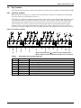
Based on your site’s specific needs, the UPS may require auxiliary connections to manage the battery
system (external battery circuit breaker, battery temperature sensor), communicate with a personal
computer or provide alarm signaling to external devices or for Remote Emergency Power Off (REPO).
Terminations for these functions are located at the front of the static bypass assembly. The main features are:
• Input and output dry contacts signal (one pair of contacts of relay)
• Emergency Power Off control (EPO)
• Environmental parameter input interface
• User communication (for data setting and user background monitor)
• Liebert IntelliSlot® interface
• Temperature detect interface
23
Electrical Connections—UPS
Figure 12 Static bypass assembly connections to display cabinet and options
Monitor
Operator Control Panel
J4
Battery Cabinet
J8
J5
Maintenance Bypass Cabinet
J12
Bypass Backfeed Protection
J11
Mains Backfeed Protection
J10
Temp Sensor (optional ) and
BCB Control Board
J4
Ground Fault (optional )
Sensor & BCB Control Board
J9
EPO (optional )
J6
Static
Bypass
Assembly
Figure 13 Auxiliary terminal block detail (static switch assembly front panel)
Input/output dry contact and EPO/BCB/MBC interface
J1∼J3 port can't connect to phone !
BFP_O
INV_O
MFP_O
MFP_C
MFP_S
BFP_C
BFP_S
INV_S
INPUT_1
J11
INV_C
INPUT_2
BCB_IN
DRIVER
GND
ENV_DET
ONLINE
+12V
BAT_GND
GND
OUT
+12V
BAT-IN
J9
BAT_READY
EPO-NO
LBS
Q3BP
J6
Q2BP
PARA
+12V
J3
J10
J8
EPO-NC
GND
J5
GND
PARA
+12V
J2
BAT-OUT
J7
EXT-OUT
J4
J1
Auxiliary
Terminal
Block
J12
NOTE
Terminal block connectors are on the left side of the static bypass assembly.
24
Electrical Connections—UPS
2.4
Dry Contacts
The UPS provides input dry contacts and output dry contacts on the Auxiliary Terminal Block (ATB).
2.4.1
Input Dry Contacts
External input dry contacts are connected via the ATB. Dry contacts are available for environment
detection, battery ground fault detection, etc.
The UPS accepts external signal from zero-voltage (dry) contacts connected through external dry contact terminals produced, and these terminals are on the static bypass assembly. Through software
programming, these signals become active when these contacts connect to +12V to ground (in the
most left side). The cables connected to the monitor board must be separated from power cables.
Moreover, these cables should be double-insulated with a typical cross-section of 0.5 to 1mm2 for a
maximum connection length between 82 and 165ft. (25-50m). The ATB has several input dry contacts.
Figure 14 Input dry contacts
12V
12V
12V
+12V
DRIVER
BCB_IN
ONLINE
Q3BP
Q2BP
J8
EXT_OUT
GND
BAT_IN
+12V
BAT_OUT
GND
ENV_DET
BAT_GND
BAT_READY-
+12V
J5
GND
J4
J9
NOTE: The black square () on each connector indicates Pin 1.
Refer to Figure 13 for the location of connectors J4, J5, J8 and J9.
Table 2
Position
J9.1
J9.2
J9.3
J9.4
J4.1
J4.2
J4.3
J4.4
Description of dry contact input port
Name
Description
ENV_DET
BAT_GND
BAT_READY
+12V
BAT_IN
+12V
BAT_OUT
GND
Detection of battery room environment (normally closed)
Battery short to ground detection
Not Used
+12V power supply
Internal battery temperature detection
+12V power supply
External battery temperature detection
Power supply GND
25
Electrical Connections—UPS
2.4.2
Output Dry Contacts
The Auxiliary Terminal Block has three output dry contact relays (see Figure 15 and Table 3).
Figure 15 Output dry contacts and EPO wiring
MFP_O
MFP_S
INV_O
MFP_C
J10
INV_S
BFP_O
BFP_C
INV_C
J12
BFP_S
J11
NOTE: The black square () on each connector indicates Pin 1.
Refer to Figure 13 for the location of connectors J10, J11 and J12.
Table 3
Output dry contact relays
Position
Name
Description
J11.2
BFP_O
Bypass feedback protection relay. Normally open. Closed when bypass SCR is shorted.
J11.3
BFP_S
Bypass feedback protection relay center
J11.4
BFP_C
Bypass feedback protection relay. Normally closed. Open when bypass SCR is shorted.
J12.2
INV_O
Inverter mode relay. Normally open. Closed when UPS is in inverter mode.
J12.3
INV_S
Inverter mode relay common
J12.4
INV_C
Inverter mode relay. Normally closed. Open when UPS is in inverter mode.
J10.2
MFP_O
Main feedback protection relay. Normally open. Closed when bypass SCR is shorted.
J10.3
MFP_S
Main feedback protection relay common
J10.4
MFP_C
Main feedback protection relay. Normally closed. Open when bypass SCR is shorted.
NOTE
All auxiliary cables of terminal must be double-insulated. Wire should be 20-16AWG stranded
for maximum runs between 80 and 200 feet (25-60m), respectively.
2.4.3
Liebert BDC Interface
The Liebert BDC interface is on the Auxiliary Terminal Block at J5. Refer to Figure 13 for the location of connector J5 and to Figure 14 for circuit details.
Table 4
Liebert BDC interface
Position
Name
Description
J5.1
Q3BP
Input circuit breaker status of external Liebert BDC
J5.2
Q2BP
Output circuit breaker status of external Liebert BDC
J5.3
EXT_OUT
J5.4
GND
Input circuit breaker status of internal Liebert BDC
Power supply GND
These contacts cannot be active unless they are set via software.
NOTE
All auxiliary cables of terminal must be double-insulated. Wire should be 20-16AWG stranded
for maximum runs between 80 and 200 feet (25-60m), respectively.
NOTE
Refer to Table 8 and Figure 23 for the Liebert BDC wiring.
26
Electrical Connections—UPS
2.4.4
Battery Cabinet Interface Connectors
The battery cabinet interface is on the Auxiliary Terminal Block at J8 and J4. Refer to Figure 13 for
the location of connectors J4 and J8 and to Figure 14 for circuit details.
Table 5
Battery cabinet interface
Position
Name
Description
J4.1
GND
Power Ground
J4.2
BAT_OUT
External Battery Temperature Detection
J4.3
+12V
J4.4
BAT_IN
Internal Battery Temperature Detection
+12V Power Supply
J8.1
DRIVER
BCB Driver Signal
J8.2
BCB_IN
BCB Contact State
J8.3
GND
J8.4
ONLINE
Power Ground
BCB On-Line - Input (N.O.) - This pin will become
active when the BCB interface is connected.
NOTE
All auxiliary cables of terminal must be double-insulated. Wire should be 20-16AWG stranded
for maximum runs between 80 and 200 feet (25-60m), respectively.
NOTE
Refer to Table 7 and Figure 19 for battery cabinet wiring.
27
Electrical Connections—UPS
2.4.5
EPO Input—Optional
The UPS has an Emergency Power Off (EPO) function operated by a button on the control panel or by
a remote contact provided by the user. The EPO button is under a hinged, clear plastic shield.
The J6 connector, shown in Figure 16, is the remote EPO input interface. The EPO has NO/NC contacts that become active when shorting terminals J6: 3 and 4 or open terminal connection J6: 2 and 1.
If an external Emergency Stop capability is required, it is connected at terminals J6: 1&2 and at J6: 3
and 4 on the monitor board. It also is connected to the Normally Open or Normally Closed remote stop
switch between these two terminals using shielded cable (see Figure 16 and Table 6). If this function is not used, terminals J6:3 and 4 must be opened and J6:1 and 2 must be closed.
Figure 16 EPO wiring and signal names for J6
+12V
EPO-NC
+12V
EPO-NC
+12V
EPO-NO
J6
EPO-NO
J6
+12V
NOTE: The black square () on each connector indicates Pin 1.
Refer to Figure 13 for the location of connector J6.
Table 6
EPO input contact relays
Position
Name
Description
J6.1
EPO_NC
EPO Activated when opened to J6.2
J6.2
+12V
EPO Activated when opened to J6.1
J6.3
+12V
EPO Activated when shorted to J6.4
J6.4
EPO_NO
EPO Activated when shorted to J6.3
NOTE
The Emergency Stop action within the UPS shuts down the rectifier, inverter and static
bypass. It does not internally disconnect the input power supply. To disconnect ALL power to
the UPS, open the upstream feeder breaker(s) when the remote EPO is activated.
NOTE
Normally Closed EPO – J6: 1, 2, these terminals are supplied factory-linked on the monitor
board and must remain installed if using NO contacts.
NOTE
All auxiliary cables of terminal must be double-insulated. Wire should be 20-16AWG stranded
for maximum runs between 80 and 200 feet (25-60m), respectively.
28
Battery Installation
3.0
BATTERY INSTALLATION
3.1
Introduction
Emerson recommends that the batteries in external cabinets be the same type and made by the same
manufacturer as the internal batteries in the Liebert APM.
If multiple sets of batteries connected in parallel are used to provide the required battery backup run
times, fit each set with an isolating device to permit working on one of the battery sets while leaving
the others in service and providing backup protection.
3.2
Safety
Special care should be taken when working with the batteries associated with the Liebert APM system equipment.
!
WARNING
The Liebert APM’s internal batteries are connected and energized even if the UPS is turned
Off. To minimize the risk of injury, a properly trained and qualified service person should
disconnect internal batteries before any maintenance is performed on the unit.
When all batteries are connected together, the battery terminal voltage may exceed 324V and
is potentially lethal.
The center of the battery is connected to the neutral of the UPS and is grounded.
A battery can present a risk of electrical shock and high short circuit current. The following
precautions should be observed when working on batteries:
• Remove watches, rings and other metal objects.
• Use tools with insulated handles.
• Wear rubber gloves and boots.
• Do not lay tools or metal parts on top of batteries.
• Disconnect charging source prior to connecting or disconnecting battery terminals.
• Determine whether the battery is grounded. If the battery is grounded, remove source of
the ground. Contact with any part of a grounded battery can result in electrical shock. The
likelihood of such shock can be reduced if such grounds are removed during installation and
maintenance
When replacing batteries, replace with batteries of the same type and manufacturer, or equivalent.
Refer to 10.2 - UPS Environmental for a list of approved batteries or contact your Emerson representative.
!
CAUTION
Batteries used in the Liebert APM and its auxiliary cabinets must be of an approved type.
Replacing batteries with an incorrect type can cause an explosion and fire. Refer to Tables 31
and 32 for acceptable batteries.
Do not dispose of batteries in a fire. The batteries may explode. Do not open or mutilate
batteries. Released electrolyte is harmful to the skin and eyes. It is toxic.
29
Battery Installation
3.3
UPS Batteries—Liebert APM 45kVA Frame Only
The Liebert APM’s internal batteries are fully charged before the unit is shipped. During storage and
transportation, some charge is lost. All batteries should be recharged before use. The battery charger
works only when the Liebert APM is connected to input power and turned On.
NOTE
Full safety instructions concerning the use and maintenance of UPS batteries are provided in
the appropriate battery manufacturer's manuals, available on the manufacturer’s Web site.
The battery safety information contained in this section relates to key considerations that must
be taken into account during the installation design process and might affect the design
outcome, depending on your installation.
3.4
External Battery Cabinet Installation
3.4.1
Matching Battery Cabinets
A matching battery cabinet is available. Refer to Figure 17. The same model battery cabinet may be
installed in parallel in multiple cabinet strings for additional capacity. Battery run time depends on
the cabinet model, the number of cabinets and the load on the UPS.
Handling—The battery cabinet has casters to facilitate movement over short distances. The bottoms
of the battery cabinets are reinforced to permit movement by forklift over longer distances.
Inspection—Remove all panels and visually inspect the batteries, bus connections, and cabinet for
any damage. Exercise caution; voltage is present within the battery cabinet even before installation.
If there are signs of damage, do not proceed. Call Liebert Services at 1-800-542-2378.
Storage—The batteries can be stored for up to six months without appreciable deterioration. If planning to store a battery cabinet for longer than six months or at temperatures higher than 77°F (25°C),
contact Liebert Services for recommended precautions.
The following notes, in conjunction with the diagrams (Figure 17), illustrate the broad principles to
be followed when fitting and connecting the majority of battery cabinet installations.
!
CAUTION
Any battery system should be installed by properly trained and qualified personnel.
When installing an external battery cabinet that is NOT a Liebert APM battery cabinet, the customer
must provide overcurrent protection. See Table 37 for sizing of protection devices.
NOTE
When using an external battery supply that is not provided with the UPS, please make
reference to the battery manufacturer’s installation manual for battery installation and
maintenance instructions, available on the manufacturer’s Web site. When replacing batteries,
Emerson recommends that the batteries in external cabinets be the same type used internally in
the Liebert APM. See Tables 31 and 32 for batteries that are approved for use with the Liebert
APM.
30
Battery Installation
3.4.2
Connecting the Batteries
If the Liebert APM battery cabinets are installed on a raised floor, the battery power cables and circuit breaker control cables may be routed to the UPS cabinet through the bottom of the cabinet.
If the Liebert APM battery cabinets are installed adjacent to one another on a solid floor, these cables
may be passed between the cabinets through slots in the lower sides of the cabinets.
Intertray connections must be made before the battery cabinet may be used.
Figure 17 Battery cabinet, 600mm wide—details
12
X8
B
Tray 1
Tray 2
34
Tray 3
40
42
Tray 4
2X 32
603705G2
ASSY BATT NXRA 600 BATT CAB HX330
603705G4
ASSY BATT NXRA 600 BATT CAB HX300
603705G5
ASSY BATT NXRA 600 BATT CAB HX205
603705G10
ASSY BATT NXRA 600 BATT CAB HX150
39
Detail B
4X
603705
Pg. 1, Rev. 1
31
Battery Installation
Figure 18 Battery trays for 600mm wide battery cabinet
HX300
HX330
HX205
HX150
32
Battery Installation
3.4.3
Installation Considerations
Position—Liebert battery cabinets come in versions specific to the left side of the UPS. If the system
includes a matching Liebert BDC, the cabinet should be mounted to the right of the UPS (nearest the
busbars) and the battery cabinet(s) should be installed to the left of the UPS.
The battery cabinet(s) are designed to be located conveniently next to each UPS module, and are also
available in stand-alone configurations with painted side panels. The front access design eliminates
side and rear service clearance requirements. Refer to Table 30 for battery cabinet dimensions and
weights.
Bolt-On Cabinets—Matching battery cabinets are designed to bolt onto the left side of the UPS
module cabinet. Use bolts that ship with each unit to connect cabinet frames at posts, two places in
the front and two places in the rear.
Service Clearance—Allow front access to the battery cabinet at all times for maintenance and servicing. Electrical codes require that the battery cabinet be installed with no less than 3 feet (1m) of
clearance at the front of the cabinet when operating. Side and rear panels do not require service clearance.
Cables—Cables may be run between the cabinets through cutouts in the top of the cabinet, eliminating the need for external conduit runs. Route cables before moving cabinets into final position for bolting together. No top or bottom entry cables are required, except for remotely located cabinets which
require conduits.
Software—To allow the UPS to accurately display the battery run time, the number of battery cabinets must be noted when performing initial startup and setup using the configuration software. This
is to be performed by the Liebert Services engineer when commissioning the unit.
Casters and Adjustable Stops—The adjustable stops are not designed to bear the full weight of the
cabinet. Lower the stops until they are finger-tight in contact with the floor. Then tighten a small
amount with a wrench (less than two turns) to give a good friction fit. When mounting the battery
cabinet on seismic stands, ensure that the casters are bearing the weight of the cabinet.
3.4.4
Connecting the Battery Cabinet to the UPS
After the battery cabinet equipment has been positioned and secured for operation and the batteries
have been connected, connect the power cables as described below (see Figure 19).
1. Verify that all incoming high and low voltage power circuits are de-energized and locked out or
tagged out before installing cables or making any electrical connections.
2. Remove the UPS right side panel to gain access to the ground and battery busbars.
3. Remove the battery cabinet front panel to gain access to the busbars.
4. Connect the safety ground and any necessary bonding ground cables to the copper ground busbar.
(example: UPS located on the bottom of the equipment below the power connections).
All cabinets in the UPS system must be connected to the user's ground connection.
NOTE
The grounding and neutral bonding arrangement must be in accordance with the National
Electrical Code and all applicable local codes.
5. Connect the system battery cables from the UPS battery terminals (+ N -) to battery cabinet
breaker BCB (+ N -) as shown in Figure 19. Be sure that the battery connections are made with
the right polarity, and tighten the connections to 240lb-in. (27N-m) (M10 bolt). Do not close the
battery circuit breaker before the equipment has been commissioned.
6. Connect TB1 from battery cabinet to J4 and J8 on the UPS according to Table 7.
NOTE
The shunt trip drive capability for the battery breaker is 220VDC at 2.4A.
33
Battery Installation
Table 7
Control wiring for Liebert APM to battery cabinet
From
To
Liebert APM UPS
Monitor Board (X2 J4 & J8)
Battery Cabinet
Terminal Strip (TB1)
J4-2
TB1-12
J4-3
TB1-11
J4-4
TB1-10
J8-1
TB1-6
J8-2
TB1-7
J8-3
TB1-8
J8-4
TB1-9
Figure 19 Battery cabinet connection to Liebert APM
34
Battery Installation
3.5
Battery Ground Fault Detection Set
In addition to any residual current device mounted externally and upstream the UPS or when
optional isolation transformers are fitted to the UPS, an optional residual battery current device can
be fitted to detect leakage current so as to ensure the normal operation of the system. Residual current range monitored: 30mA ~ 3000mA
Power supply: 208VAC (L-L)
When a battery ground fault is detected, an alarm will appear on the UPS display panel.
The battery ground fault detection set contains one current transformer and one DC-sensitive residual current monitor. The connection of this set for UPS is shown in Figure 20.
Figure 20 Wiring of battery ground fault detection set
Current Transformer
W4-A140S
Battery
Cabinet
Battery Cabinet
Breaker
Batt_+
Batt_N
Batt_-
X
X
K1
K2
I2
+15V
208VAC
UHW241M5
Power Board
GND
-15V
4 +12V
J5
J1
2
BAT_GND
J9
Battery Ground
Fault Detection Device
ULC3661SCI
3.6
Static Bypass
Module
I2
APM
Non-Standard Batteries
When batteries other than a matching battery cabinet are used, a remote battery disconnect switch
with overcurrent protection is required per the National Electrical Code. Contact your local Emerson
sales representative about this option. Refer to Figures 57 and 58 for details.
Install battery racks, cabinets and batteries in accordance with the manufacturer's instructions.
Verify that the battery area has adequate ventilation and battery operating temperature complies
with the manufacturer's specifications and with all applicable national and local codes.
If you have any questions concerning batteries, battery racks or accessories, contact Liebert Services
at 1-800-543-2378.
NOTE
The user-supplied battery DC bypass breakers or fuses should have a minimum overload
rating of 8kA and 500V.
35
Liebert BDC
4.0
LIEBERT BDC
The Liebert BDC is designed to operate in UPS mode, bypass mode and maintenance mode.
Figure 21 Single UPS with external Liebert BDC—typical configuration
4.1
Normal (UPS) Mode
While the Liebert BDC is in Normal mode (MBB open; BIB/MIB closed), the UPS is supplying the
connected load with continuous, high-quality AC power. In this mode of operation, the load is protected by the UPS.
4.1.1
Bypass Mode
When the Liebert BDC is in Bypass mode, it provides an alternate path for power to the connected
equipment. Should the UPS need to be taken out of service for limited maintenance or repair, manual
activation of the bypass will cause an immediate transfer of the equipment from the UPS inverter to
the bypass source. In this mode, power will still be supplied to the UPS; however, the load is NOT protected by the UPS.
36
Liebert BDC
4.2
Maintenance Mode
When the Liebert BDC is in Maintenance mode (MBB closed; BIB/MIB open), it provides an alternate
path for power to the connected equipment. Should the UPS need to be taken out of service for limited
maintenance or repair. In this mode of operation, no power is supplied to the UPS and the load is
NOT protected by the UPS.
4.3
Locating the Cabinet
This Liebert BDC may be mounted to the left of the UPS or installed as a stand-alone unit. In either
case, ensure that the unit is in a well-ventilated area and that there is clearance for access to the
switches and cable connections as required by national and local codes.
4.4
Cable Installation
4.4.1
Wiring Preparation
Be sure that the unit is not connected to any AC utility power source or UPS before installing any wiring to this unit. This Liebert BDC should be installed by a qualified / certified electrician.
!
WARNING
Please read this section thoroughly before attempting to install wiring to this unit.
Removing the Cover Plates
Plates cover the input and output terminals on the front of the Liebert BDC (see Figure 22). Remove
these and keep the screws and plates for reinstallation.
Figure 22 Liebert BDC—access plate removed
4.4.2
Power Cable Installation
Refer to Table 37 when selecting cables.
NOTE
Transient and steady state earth leakage currents may occur when starting the equipment.
This should be taken into account when selecting ground current detection devices because
these will carry the earth leakage currents of both the UPS equipment and the load.
37
Liebert BDC
4.4.3
Input/Output Wiring
Follow the steps below to connect the input wiring:
NOTE
Input wiring must be installed using conduit if cabinet is not mounted to the immediate right
of the UPS.
1. Locate the input wiring access (top or bottom access), remove the conduit landing plate and punch
the appropriate size hole for the size conduit being used. Pull the three/four input wires through
it, allowing some slack for installation. For cabinets that are located to the immediate left of the
UPS, the access plate is on the lower right of the cabinet. Remove the access plate and verify that
the edge guarding is installed and intact.
2. Secure the conduit to the access plate of the Liebert BDC.
3. Input power cables connect to the system input circuit breaker; refer to Figure 33 and to
Table 13.
4. Connect the ground (earth) wire to the earth busbar and tighten it to 240lb-in. (27N-m) (M10
bolt).
5. Locate UPS input and output cables and access panel to UPS on lower right side.
NOTE
If the Liebert BDC is not to be bolted to the UPS, use either top or bottom access plate.
6. Connect the system ground cable between the Liebert BDC and UPS and tighten the connections
to 240lb-in. (27N-m) (M10 bolt).
7. Connect the system input cables between the Liebert BDC “UPS Input” Busbars (A-B-C N
terminals) and UPS input busbars (A-B-C N terminals) and tighten the connections to 240lb-in.
(27N-m) (M10 bolt).
8. Connect the system output cables between the Liebert BDC 'UPS Output' Busbars (A-B-C N
terminals) and UPS output busbars (A-B-C N terminals) and tighten the connections to 240lb-in.
(27N-m) (M10 bolt).
9. Connect TB1 from the Liebert BDC to J5 and J12 on the Liebert APM.
!
Table 8
WARNING
The control wire must be installed to ensure proper operation of the system and fully protect
the load when switching between bypass cabinet and UPS.
Control wiring for Liebert APM UPS to Liebert BDC
From
To
Liebert APM UPS Monitor
Board (X2 J5 & J12)
Liebert BDC Terminal Strip (TB1)
J12-3
TB1-11
J12-4
TB1-12
J5-1
TB1-3
J5-3
TB1-6
J5-4
TB1-5
Jumper TB1-4 to TB1-5
38
Liebert BDC
Figure 23 BDC connection to Liebert APM
NOTE
Install jumper on TB1 pins 4 and 5.
For startup procedure, see 9.2 - UPS Startup.
39
Liebert BDC
4.5
Bolting Cabinets Together
NOTE
UPS wiring must be completed before the cabinets are bolted together.
1. Line up cabinets so that mounting holes are aligned.
Figure 24 Bolting Liebert APM to a Liebert BDC
A
Place cabinets so mounting
holes are aligned.
A bolt from the adjacent
cabinet may be screwed into
the threaded top hole, or a
bolt may be inserted
through the lower hole and
screwed into the threaded
hole in the adjacent cabinet.
Hardware for bolting units is in a bag attached to
the Liebert APM. See form included with UPS.
2. Using supplied hardware, bolt the cabinets together. The bolts may be inserted from either the
UPS side or from the Liebert BDC side, whichever is more convenient.
40
Installation Drawings
5.0
INSTALLATION DRAWINGS
The diagrams in this section illustrate the key mechanical and electrical characteristics of the Liebert
APM UPS System cabinets (UPS, Liebert BDC and battery).
Figure 25 UPS dimensions- front view
Figure 26 Lineup arrangement, Liebert APM with battery and Liebert BDCs
41
Installation Drawings
Figure 27 UPS dimensions continued, center of gravity—side, top and bottom views
Refer to Tables 9 and 10 for Dimensions X, Y and Z in each Liebert APM model.
42
Installation Drawings
Table 9
Center of gravity and weights for Liebert APM 90 kVA frame UPS
Center of Gravity
Weight, lb (kg)
KVA Rating
Dimension X
Dimension Y
Dimension Z
Unit
Shipping
No Internal Batteries
15
16.65 (423)
37.64 (956)
18.78 (477)
705 (320)
775 (352)
30
16.18 (411)
38.66 (982)
18.54 (471)
780 (354)
850 (386)
45
15.79 (401)
39.88 (1013)
18.35 (466)
855 (388)
925 (420)
60
15.47 (393)
41.30 (1049)
18.15 (461)
930 (422)
1000 (454)
75
15.16 (385)
42.87 (1089)
17.99 (457)
1005 (456)
1075 (488)
90
14.88 (378)
44.57 (1132)
17.83 (453)
1080 (490)
1150 (522)
Table 10
Center of gravity and weights for Liebert APM 45 kVA frame UPS
Center of Gravity
Weight, lb (kg)
KVA Rating
Dimension X
Dimension Y
Dimension Z
Unit
Shipping
919 (417)
989 (449)
No Internal Batteries
15
15.87 (403)
36.18 (919)
18.31 (465)
30
15.71 (399)
37.64 (956)
18.19 (462)
994 (451)
1064 (483)
45
15.59 (396)
39.13 (994)
18.07 (459)
1069 (485)
1139 (517)
1981 (899)
2051 (930)
12HX100 Batteries
15
14.29 (363)
31.50 (800)
21.30 (541)
30
13.94 (354)
33.46 (850)
21.59 (548.4)
2052 (931)
2122 (963)
45
13.62 (346)
35.04 (890)
21.73 (552)
2127 (965)
2197 (997)
12HX150 Batteries
15
14.25 (362)
30.91 (785)
21.54 (547)
2455 (1114)
2525 (1145)
30
13.78 (350)
32.87 (835)
21.81 (554)
2530 (1148)
2600 (1179)
45
13.39 (340)
34.72 (882)
22.05 (560)
2605 (1182)
2675 (1213)
43
Installation Drawings
Figure 28 UPS main components—typical unit
Liebert APM 45kVA Frame
Liebert APM 90kVA Frame
44
Installation Drawings
Figure 29 UPS cable connections—45kVA and 90kVA frames
45kVA frame
90kVA frame
45
Installation Drawings
Figure 30 Battery cabinet connection to UPS
Refer to Table 11
for interconnect
wiring
46
Installation Drawings
Table 11
Run
Interconnect wiring for Liebert APM to battery cabinet
From
To
Conductors
A
UPS Battery Busbar
External Battery Cabinet Busbar
Positive, Midpoint, Negative
B
Battery Cabinet Terminal Block TB1
UPS Static Bypass Assembly
J4 and J8
Battery Breaker Shunt and Aux Contacts
See Figure 19 for additional details.
NOTE
Wiring is supplied when the UPS and external battery cabinet are ordered as a system.
Figure 31 Battery cabinet outline drawing, weights and center of gravity
47
Installation Drawings
Figure 32 Outline drawing, Liebert BDC for Liebert APM, 15-90kVA
48
Installation Drawings
Figure 33 Liebert BDC connection to UPS
49
Installation Drawings
NOTES
1. All Liebert-supplied cable must be repositioned prior to and while the cabinets are being placed in
their final installed location.
2. All interconnection hardware supplied by Liebert.
3. AC connections must be made to the UPS module before attaching Liebert BDC to UPS module.
4. All cabling will be field-supplied when a Liebert BDC is configured as a stand-alone cabinet.
5. Liebert BDCs must attach to the right side only of the Liebert APM.
6. Refer to the individual drawing of each piece of equipment for additional details.
Table 12
Run
Interconnect wiring for Liebert APM to Liebert BDC
From
To
Conductors
A
Utility AC source
BDC System Input Bus
Phase A, B, C
B
Utility AC Source
BDC System Input Bus
Neutral
C
BDC Bypass Isolation Breaker
UPS Main Input
Phase A, B, C
D
BDC Bypass Isolation Breaker
UPS Main Input
Neutral
E
UPS Output
MBC Maintenance Isolation Breaker
Phase A, B, C
F
UPS Output
MBC Maintenance Isolation Breaker
Neutral
G
BDC Panelboard
Load AC Connection
Phase A, B, C
H
BDC Panelboard
Load AC Connection
Neutral
I
Utility AC Source
All Ground Connections
Ground
J
BDC Terminal Block TB1
UPS Static Bypass Module J5 and J12
Wiring for KO on MBC
See Figure 23 and Table 8 for additional details.
NOTE
Wiring is supplied when the UPS and Liebert BDC are ordered as a system.
Table 13
Spring washer torque application
Hardware
Two Belleville Washers
M10 (3/8")
240 lb-in. (27 N-m)
Figure 34 Acceptable hardware configuration for torque application
50
Installation Drawings
Figure 35 Seismic mounting bracket details
51
Option Installation
6.0
OPTION INSTALLATION
6.1
Liebert IntelliSlot Communication
The Liebert APM has three Liebert IntelliSlot ports to allow field-installation of optional
communication cards. Liebert IntelliSlot cards communicate via Liebert’s proprietary Velocity
protocol to cards that translate the information into such protocols as SNMP and Modbus. Other
cards provide dry contact signals for external signaling of operating status.
The Liebert IntelliSlot communication ports may be installed or removed while the Liebert APM is
operating.
6.2
Liebert IntelliSlot Web Card—SNMP/HTTP Network Interface Card
This network interface card provides all real-time data and status information as SNMPv1 traps for
connection to a 10/100-baseT Ethernet connection. The same card also will transmit the same status
information and all measured parameters for display via a Web browser. The Liebert IntelliSlot bays
are on the right side of the control module and labeled as IntelliSlot1, IntelliSlot2 and IntelliSlot3.
Table 14 Liebert APM communication options
Port Type and
Location
Labeled ID
Name of Port
Monitoring
Devices Supported
MultiPort 4
Left Liebert
IntelliSlot
IntelliSlot 1
Relaycard-int
ISWEB-L
Modbus
MultiPort 4
Center Liebert
IntelliSlot
IntelliSlot 2
Relaycard-int
ISWEB-L
Modbus
MultiPort 4
Right Liebert
IntelliSlot
IntelliSlot 3
Relaycard-int
ISWEB-L
Modbus
52
Option Installation
6.3
Web Card—Optional
An optional Web card is available that provides remote access to the UPS. A wide variety of status
and summary information is available through an Ethernet connection.
Figure 36 Liebert IntelliSlot Web card display
53
Option Installation
6.4
Relay Card
The relay card provides voltage-free contact closures for remote monitoring of alarm conditions.
Delivering On Battery, On Bypass, Low Battery, Summary Alarm, UPS Fault and On UPS signals, the easy-to-install card integrates with AS/400 computers (additional cable required) and other
relay contact monitoring systems.
The relay card is rated for 24 VAC/DC at 1A. and supported in any of the three Liebert IntelliSlot
bays on the Liebert APM.
Table 15
Relay Card pin configuration
Pin
Function
Operation
1
UPS Fault
Closed if no UPS failure
2-3
Not Used
4
UPS Fault
Closed if UPS fails
5
Summary Alarm**
Closed if SUMMARY ALARM** occurs
6
Summary Alarm**
Closed if no alarm conditions are present
7
Any Mode Shutdown return
Not supported – use External EPO terminal
8
Not Used
9
Common - Low Battery
10
Low Battery
Closed if battery is OK
11
Low Battery
Closed if LOW BATTERY point occurs.
12-13
Not Used
14
UPS Any Mode Shutdown
Not supported – use External EPO terminal
15
On UPS
Closed if ON UPS (inverter) power
16
On Battery
Closed if ON BATTERY power (Utility failure)
17
Common - UPS Fault,
Summary Alarm, On UPS, On
Battery, On Bypass
18
On Battery
19-23
Closed if not ON Battery power (Utility OK)
Not Used
24
On Bypass
25
Not Used
Closed if ON BYPASS
**A Summary Alarm occurs when any of the following conditions exist:
1. Utility power is out of the acceptable range (voltage and/or frequency).
2. UPS is in BYPASS MODE (load not on Inverter power).
3. UPS Battery is LOW.
4. UPS fault has occurred.
Table 16
Relay card jumper configuration
Number
Connection
Description
JP01
Pin 9 to Pin 17
Allows all relay COMMONS to be tied together.
Any JP02
Pin 7 to Pin 17
REMOVE - Interconnects all relay COMMONS and the (not supported)
MODE SHUTDOWN Return
54
Option Installation
6.5
Liebert IntelliSlot MultiPort 4 Card
The Liebert IntelliSlot MultiPort 4 card provides four sets of voltage-free contact closures for remote
monitoring of alarm conditions UPS operation On Battery and battery low condition. A typical
application is to allow a maximum of four computer systems to simultaneously monitor the status
(e.g., utility power failure-low battery) of a single UPS.
This card is supported in any of the three Liebert IntelliSlot bays on the Liebert APM.
Figure 37 Liebert IntelliSlot MultiPort 4 card pin assignment
CPU
Pin
CPU
UPS
CPU
CPU
6.6
Assignment
Description
1
Low Battery
2
Not Used
3
Not Used
4
Not Used
5
Not Used
6
Not Used
7
Low Battery Common
8
Utility Fail Common
9
Utility Fail
Alber BDSi Battery Monitoring System—Optional
The matching Liebert battery cabinets allow installing an optional Alber BDSi battery monitoring
system inside the cabinet. The Alber BDSi by Liebert continuously checks all critical battery parameters, such as cell voltage, overall string voltage, current and temperature. Automatic periodic tests of
internal resistance of each battery will verify the battery's operating integrity. Additional capabilities
include automatic internal DC resistance tests and trend analysis providing the ability to analyze
performance and aid in troubleshooting.
The Alber BDSi system is installed inside the battery cabinet as shown in Figure 30. The monitoring
system power inlet is wired to the Alber BDSi Fuse Block on the UPS (see Figure 38). The Alber
BDSI fuse block supplies 120VAC and has an 8A fuse.
If required, power can be supplied from the output terminals of the UPS, a distribution panel or
another UPS-protected source.
For details about operating the Alber system, see the Alber Monitoring System manual.
55
Option Installation
Figure 38 Alber BDSi controller and input connection
Rear Panel
120VAC 50/60Hz
Input
56
Option Installation
6.7
Battery Temperature Compensation
For a UPS with external batteries, an optional battery temperature interface optimizes the external
battery management by connecting up to four external temperature sensors from the battery cabinets
to a control unit inside the UPS.
Figure 39 Multi-temperature sensors
Temperature
Sensor
+
IN
TMP-2
X103
NC
12V
OUT
GND
Temperature
Sensor
X104
NC
12V
OUT
GND
+
IN
TMP-2
X108
12V
OUT
GND
Temperature
Sensor
X105
NC
12V
OUT
GND
+
IN
TMP-2
BCB Control
Board
Temperature
Sensor
X106
NC
12V
OUT
GND
+
IN
TMP-2
57
Monitor
Board
– X2
+12V
BAT_OUT
GND
Static
J4
Bypass
Module
Operation
7.0
OPERATION
!
WARNING
The Liebert APM contains high voltages internally. Components that can only be accessed by
opening the protective cover with tools cannot be serviced or replaced by the user.
Only properly trained and qualified service personnel are authorized to remove the protective
covers.
The Liebert APM operates in the modes shown in Table 17. This section describes various kinds of
operating procedures under each operating mode, including transfer between operating modes, UPS
setting and procedures for turning on/off inverter.
Table 17 UPS operating modes
Operating mode
Descriptions
Normal mode
NORMAL
UPS powers the load
Bypass mode
BYPASS
The load power supply is provided by the static bypass. This mode can be regarded
as a temporary transition mode between the normal mode and maintenance bypass
mode, or a temporary abnormal operating status
Maintenance
Mode
MAINT
UPS shuts down, the load is connects to the mains through the Liebert BDC. In this
mode the load is not protected against abnormal input utility power.
As shown in Figure 40, the AC utility source is supplied through the input breaker, and the rectifier
converts the alternating current into DC power. The inverter converts the AC power from the utility—or DC power from the batteries—into AC power for the load. The batteries power the load
through the inverter in the event of a power failure. The utility source can also power the load
through the static bypass.
If maintenance or repair of the UPS is necessary, the load can be switched without interruption in
service using the Liebert BDC.
Figure 40 Single module block diagram—Single input configuration with three-breaker Liebert BDC
58
Operation
Figure 41 Single module block diagram—Dual input configuration with three-breaker Liebert BDC
7.1
Static Bypass Switch
The circuit block labeled “Static Bypass” in Figure 40 contains an electronically controlled switching
circuit that enables the critical load to be connected to either the inverter output or to a bypass power
source via the static bypass line. During normal system operation the load is connected to the inverter
and the inverter contactor is closed; but in the event of a UPS overload or inverter failure, the load is
automatically transferred to the static bypass line.
To provide a clean (no-break) load transfer between the inverter output and static bypass line, the
static switch activates, connecting the load to bypass. To achieve this, the inverter output and bypass
supply must be fully synchronized during normal operating conditions. This is achieved through the
inverter control electronics, which make the inverter frequency track that of the static bypass supply,
provided that the bypass remains within an acceptable frequency window.
NOTE
When the UPS is operating in static bypass mode or on maintenance bypass, the connected
equipment is not protected from power failures or surges and sags.
59
Operation
7.2
Operating Modes
The UPS is designed to operate as an on-line, double-conversion, reverse-transfer system in the following modes:
•
•
•
•
•
•
Normal Mode
Battery Mode
Auto-Restart Mode
Bypass Mode
Battery Start Mode
Maintenance Mode (Manual Bypass)
Normal Mode
Operating in normal mode, the Liebert APM’s rectifier derives power from a utility AC source and
supplies regulated DC power to the inverter, which regenerates precise AC power to supply the connected equipment. The rectifier also uses the utility source power to charge the batteries.
Battery Mode
When utility AC power fails, the Liebert APM protects the critical load by instantaneously channeling
battery power to the inverter which continues supporting the critical load without interruption. When
utility power returns and is within acceptable limits, the Liebert APM automatically shifts back to
Normal mode, with the rectifier powering the critical load.
Auto-Restart Mode
The battery may become exhausted following an extended AC utility failure. The inverter shuts down
when the battery reaches the End of Discharge voltage (EOD). The UPS may be programmed to “Auto
Recovery after EOD” after a delay time if the AC utility recovers. This mode and any delay time may
be programmed by the commissioning engineer.
Bypass Mode
When the Liebert APM is in bypass mode, the load is directly supported by utility power and is without battery backup protection.
The Liebert APM’s static transfer switch will shift the load from the inverter to bypass mode without
an interruption in AC power if the inverter is synchronous with the bypass and any of the following
occurs:
• inverter fails
• inverter overload capacity is exceeded
• inverter is manually turned off by user
NOTE
If the inverter is asynchronous with the bypass, the static switch will transfer the load from the
inverter to the bypass WITH interruption in AC power to the critical load. This interruption
will be less than 15ms (in 50Hz), or less than 13.33ms (in 60Hz). This interruption time may be
altered by modifying the Output transfer interrupt time setting.
Battery Start Mode
The battery start option permits starting the Liebert APM with power supplied only by the batteries
(at charged condition).
Maintenance Mode
For maintenance or repair, the Liebert APM may be operated in maintenance mode. To place the Liebert APM in maintenance mode, follow the instructions in 9.4 - Switching the UPS from Normal
Operation to Maintenance Bypass.
!
WARNING
The UPS input and output must be protected with external overcurrent protection devices. In
maintenance mode, the input and output busbars remain energized.
60
Operator Control and Display Panel
8.0
OPERATOR CONTROL AND DISPLAY PANEL
8.1
Operator Control Panel
The control panel and LCD on the front of the Liebert APM lets the operator:
•
•
•
•
Turn the UPS On or Off
Transfer into the various operating modes
Silence alarms
Check the status of the UPS and its batteries, including all measured parameters, events and
alarms
The main areas of the control panel are shown below in Figure 42 and explained in Table 18.
• Mimic Display - view the status of the Liebert APM in single-line diagram format—indicators
show status by changing color when ON, flashing or OFF
• Liquid Crystal Display (LCD) and Navigation keys - view status and operational data from
the Liebert APM in tabular format
• Control buttons - turn the Liebert APM on or off, silence alarms
Figure 42 Overview of control panel
E ME R S O N
TM
8
Network Power
Mimic
current
path
3
4
1
5
Control
buttons
EPO
2
FAULT CLE AR
INV E RTE R OFF
6
STATUS
7
S ILE NCE ON/ OFF
F1
F2
F3
F4
HELP
INV E RTE R ON
LCD and Menu Buttons
Table 18
Descriptions of UPS operator control and display panel
Mimic Current Path
Item #
Control Buttons
Function
Button
Function
1
Rectifier indicator (AC to DC)
EPO
EPO switch
2
Battery indicator (backup DC power)
INVERTER ON
Inverter start button
3
Bypass input indicator
INVERTER OFF
Inverter shutdown button
4
Inverter indicator (DC to AC)
FAULT CLEAR
Fault reset button
5
Load indicator (AC output)
SILENCE ON/OFF
Alarm mute button
6
UPS status and alarm indicator
7
Audible alarm (buzzer)
8
Protective cover for EPO button
Menu Buttons
Button
F1 through F4 and HELP
Function
LCD menu keys
NOTE
Help button menus are not active. Future units will ship with an F5 legend in place of the
HELP legend.
61
Operator Control and Display Panel
8.2
Mimic Display Indicators
Figure 43 Mimic display indicators location
E ME R S O N
TM
3
Network Power
Mimic indicators
1. Rectifier indicator
2. Battery indicator
3. Bypass indicator
4. Inverter indicator
5. Load indicator
6. Status indicator
4
5
2
STATUS
6
1
Mimic indicators show the operational status of the Liebert APM by their color—green, amber or
red—and whether they are ON (solid), flashing or OFF. Table 19 provides a guide to interpreting the
various states of the indicators.
Table 19
Mimic display status indicators
Indicator
(see Figure 43)
Green
Flashing Green / Amber
Red
Off
1. Rectifier
Load on Rectifier
Flashing Green: Utility normal,
Rectifier fault
but rectifier not operating
Rectifier is normal, but utility
is abnormal
2. Battery
Battery Powering
the Load
Flashing Green: Battery
pre-warning (low battery)
Battery or battery
converter abnormal*
Battery and converter are
normal, and battery is not
discharging
3. Bypass
Load on Bypass
Power
Bypass out of
normal range
Bypass Normal
4. Inverter
Inverter Powering Flashing Green: Inverter on
the Load Normally standby
Inverter fault
Inverter normal, but Off
5. Load
UPS output On
UPS output overloaded
UPS has no output power
6. Status
No Alarms—UPS Amber: UPS has a general
Working Normally alarm
—
—
UPS has a serious alarm
—
* Battery or battery converter abnormal events include these event messages (see Table 1 in Appendix A): No Battery, Battery Replaced,
Battery Reverse, Batt. Conv. Over. Curr., Batt. Converter Fault, Batt. Converter Overtemp.
62
Operator Control and Display Panel
8.3
Control Buttons
The Control Buttons on the front panel may be used to shut down the UPS completely, turn the
inverter on or off, restart the UPS after a fault and silence the alarm, as shown in Figure 44. The
function of each button is described in Table 20.
NOTE
To activate a button properly, press and hold until you hear a short beep—about two seconds.
Figure 44 Control button layout
EPO Button Cover
EPO Button
E MER SO N
Inverter Off Button
TM
Network Power
EPO
STATUS
Fault Clear Button
FAULT CLE AR
INV E RTE R OFF
Silence On/Off Button
S ILE NCE ON/ OFF
F1
F2
F3
F4
HELP
INV E RTE R ON
Inverter On Button
LCD Navigation Keys
Table 20
Control buttons
Button
(see Figure 44)
8.4
Function
EPO
Completely shuts down the UPS, including the static switch.
CAUTION: Use caution before pressing the Emergency Power Off (EPO) button. This
button completely shuts down the unit and the critical load.
INVERTER ON
Press this button to start the inverter and transfer from static bypass to inverter.
NOTE: If the inverter is not ready, this will not activate the UPS.
INVERTER OFF
Press this button to shut down the inverter during operation. The load will be transferred
to static bypass.
FAULT CLEAR
After the UPS shuts down due to a fault and the alarm condition has been resolved, press
this button to clear the fault and restart the UPS.
SILENCE ON/OFF
Press this button once to silence the alarm buzzer when an alarm is active. Any new fault
will sound the buzzer again.
If the alarm buzzer is not beeping, press this button to test the alarm sound.
Alarm Buzzer
The alarm buzzer produces three types of sounds:
• Single beep - when any Control button is pressed
• Single beep repeating every two seconds - the system has a general alarm
• Continuous - the system has a serious fault
If the alarm buzzer makes no sound, the system may be operating properly or the alarm may have
been silenced manually.
63
Operator Control and Display Panel
Figure 45 Alarm buzzer location
E ME R S O N
TM
Network Power
EPO
FAULT CLE AR
INV E RTE R OFF
STATUS
S ILE NCE ON/ OFF
F1
F2
F3
F4
HELP
INV E RTE R ON
Buzzer
8.5
LCD Overview
The LCD on the front panel has five main sections, as shown in Figure 46. Press the F1 key below
the LCD to scroll through these sections.
•
•
•
•
UPS system information - view UPS name and model, date and time, overall status.
LCD Menu - choose a category of data items to appear below the menus (see Table 22).
Data and settings - view data items for the selected menu (see Table 22).
Current status messages - check the most recent UPS event and alarm messages (see Table 1
in Appendix A).
• Navigation key icons - look at the icon above each navigation key to determine how the key
operates when pressed (see 8.6 - Navigation Keys).
The LCD displays alarm information in real time. After appearing in the current status section of the
LCD, status messages are stored in the history log—512 records can be stored and retrieved.
Figure 46 Sections of the LCD
UPS System Information
Single
Current status
Time
APM 090 kVA
Alarms
02:17:47
L1-N/L2 L2- N/L3
L-N voltage (V) 121.4 122.7
L-N current (A) 12.2
14.2
Frequency (Hz) 59.96 59.96
L-L voltage (V) 211.3 211.6
Power factor
0.00
0.00
L3-N/L1
121.7
13.5
59.96
210.5
0.00
E-Mail
Notification
Icon
Mains
Current menu
Menu icons
Return to Main
Menu
Move to
Next Menu
F1
F2
F3
64
F4
HELP
Operator Control and Display Panel
8.6
Navigation Keys
The navigation keys on the front panel—F1 through F4 and Help—are used to access the LCD to view
the current status and other information about the Liebert APM.
Navigation key icons on the LCD appear above each key to indicate its operation (see Table 21). The
keys are “soft keys” that can change functions according to the icon.
• Use F1 to move to the home portion of the LCD.
• Use F3 and F4 as cursor keys to move left and right or up and down, depending on the icons displayed above the keys.
• Use F2 as an ESC key.
• Use HELP to access help information on the LCD or to enter a choice.
Table 21
Key
Icons for navigation keys
F1
Functions
Available
Home
F2
F3
F4
HELP
ESC
Left
Right
Enter
?
Exit
Up
8.7
Down
Help
LCD Menus and Data Items
The LCD menus provide access to the following categories of information and settings for the UPS.
Selecting a menu changes the information displayed in the UPS data items portion of the LCD. The
menu choices are listed below and described in detail in Table 22.
• Mains - view utility power input data: voltage, current, frequency and power factor
• Bypass - view bypass data: voltage and frequency
• Output - view output data: voltage, current, frequency and power factor
• Load - view load data: load percent, output current, output power and crest factor (CF)
• System - view system data
• Battery - view battery characteristics—voltage, current, temperature, remaining time and capacity—and messages when the battery is boost/float charging or disconnected
• Events - view the events log—displays all recent events added to the log (new records added at
end)
• Records - access the history log—displays all records in the log (new records added at end)
• Language - select a language for LCD text (choices appear in the native language)
• Settings - configure UPS settings: adjust the display contrast, choose a format for date display,
set the date and time, set up the UPS for modem communications (baud rate, address, mode and
phone numbers to dial for alarm notifications) and change the password
• Command - start or stop a battery maintenance test, battery capacity test or system test
• Run Time - view available backup time for the UPS and bypass
• Version - view firmware versions for the inverter, rectifier and software display board and the
model information for the UPS
Figure 47 shows a menu tree of the options available from the LCD menus.
65
Operator Control and Display Panel
Figure 47 Menu tree
Mains (input)
Bypass
Output
Load
System
L-N voltage (V)
L-N current (A)
Frequency (Hz)
L-L voltage (V)
Power factor
L-N voltage (V)
Frequency (Hz)
L-L voltage (V)
L-N voltage (V)
L-N current (A)
Frequency (Hz)
L-L voltage (V)
Power factor
Sout (kVA)
Pout (kW)
Qout (kVAR)
Load level %
Crest factor
Sout (kVA)
Pout (kW)
Qout (kVAR)
Battery
Events
Records
Language
Battery voltage (V)
Battery current (A)
Battery temperature (°C)
Remain Time Min.
Battery capacity (%)
Battery boost charging
Battery float charging
Battery disconnected
(events log)
(history log)
(Choices for
display)
Settings
Command
Run Time
Version
Display contrast
Date format set
Date & time
Comm1 baud rate
Comm2 baud rate
Comm3 baud rate
Communication address
Communication mode
Callback times
Phone No.1
Phone No.2
Phone No.3
Command password
Protocol
Battery maintenance test
Battery capacity test
System test
Stop testing
Freshening Charge
Stop Freshening Charge
Modem Auto-answer enable
UPS Run Time
Byp Run Time
Monitor version
Rectifier version
Inverter version
Bypass version
UPS model
66
Operator Control and Display Panel
8.8
Language Selection
The LCD menus and data display are available in 12 languages (Chinese, Dutch, English, French,
German, Italian, Japanese, Polish, Portuguese, Russian, Spanish and Swedish). To select a different
language:
1. From the main menu, press the F4 (shift) key to move the cursor to the Language menu at the
bottom of the screen.
2. Press HELP to access the language choices.
3. Press F3 and F4 (left and right arrows) as needed to highlight the desired language.
4. Use HELP to select the required language.
5. Return to the main menu by repeatedly pressing F2 (ESC) and F1.
All text on the LCD will now be displayed in the selected language.
Figure 48 Language selection screen
Single
POLSKI
APM 090 kVA
02:17:47
ENGLISH
DEUTSCH
FRANCAIS
ITALIANO
ESPANOL NEDERLANDS SVENSKA
PORTUGUES
Language
F1
8.9
F2
F3
F4
HELP
Current Date and Time
To change the system date and time:
1. From the main menu, press the F4 (shift) key to move the cursor to the Settings menu at the
bottom of the screen.
2. Press HELP to select the Settings menu.
3. Use F3 and F4 (up and down) to select the Date & Time option, then press HELP (enter).
4. Use F4 to position the cursor on the row where the date and time are displayed, then press
HELP (enter).
5. Using the F3 (up), enter the current time and date information.
6. Press HELP (enter) to save the settings.
7. Press F2 (ESC), then F1 to return to the main screen.
67
Operator Control and Display Panel
Figure 49 Date and time screen
Single
APM 090 kVA
02:17:47
D is p la y c o n t r a s t
D a t e f o r ma t s e t
D / M/ Y
D a t e & t ime
2 0 1 0-0 7 - 1 5
Y / M/ D
Y / M/ D
M/ D / Y
0 2: 1 7 : 4 5
Settings
F1
8.10
F2
F3
F4
HELP
UPS History Log
The Liebert APM displays status changes as they occur and stores that data in the history log, as
shown in Figure 50.
• History Log: When a record moves to the history log, the time the status changed is recorded.
The history log can hold up to 512 records. History log records may be viewed by accessing the
Records menu.
Figure 50 History log records
Single
APM 090 kVA
1 Ma in s v o lt . a b n o r ma l
2 0 1 0-0 6 - 0 7
2 0 1 0-0 6 - 0 7
3 Ma in s v o lt . a b n o r ma l
2 0 1 0-0 6 - 0 7
2 0 1 0-0 6 - 0 7
6 Ma in s v o lt . a b n o r ma l
2 0 1 0-0 6 - 0 7
2 0 1 0-0 6 - 0 7
Records
F1
F2
F3
02:17:47
0 9 : 4 8: 1 0
0 9 : 4 8: 1 0
0 9 : 4 8: 1 0
0 9 : 4 8: 1 0
History log
(records menu)
0 9 : 4 8: 1 0
0 9 : 4 8: 1 0
F4
HELP
See Table 1 in Appendix A for a complete list of status messages, along with a description and any
recommended actions.
68
Operator Control and Display Panel
8.11
Types of LCD Screens
This section provides a quick guide to the main types of LCD screens.
8.11.1 Opening Display
As the UPS begins powering up, the opening display appears, as shown in Figure 51.
Figure 51 Opening display
Single
APM 090 kVA
02:17:47
EMERSON™
Network Power
Liebert
®
Pr ess any key back to m ain m enu
F1
F2
F3
HELP
F4
8.11.2 Default Screen
After the UPS has powered up and completed a self-test, the output screen appears, as shown in
Figure 52. This window is the default screen.
Figure 52 Default screen
Single
APM 090 kVA
02:17:47
L1-N/L2 L2- N/L3
L-N voltage (V) 118.4 119.2
L-N current (A) 0.0
0.0
Frequency (Hz) 59.97 59.97
L-L voltage (V) 205.7 208.4
Power factor
0.00
0.00
L3-N/L1
121.6
13.5
59.97
207.9
0.00
Output
F1
F2
F3
69
F4
HELP
Operator Control and Display Panel
8.11.3 UPS Help Screen
Press the HELP key below the LCD to display the Help window. (Press the HELP key again to exit
the Help window.)
8.11.4 Screen Saver Window
If there has been no interaction with the Liebert APM’s LCD for 2 minutes, the screen saver window
appears. It remains on the LCD for 2 minutes, then the screen will go dark. The LCD will become
active again when any key is pressed.
Figure 53 Screen saver window
Single
APM 090 kVA
02:17:47
EMERSON™
Network Power
Liebert
®
Pr ess any key back to m ain m enu
F1
F1
8.12
F2
F2
F3
F3
F4
F4
HELP
HELP
Pop-Up Windows
Pop-up prompt windows appear when the user must confirm a choice or perform an operation. This
section describes the pop-up windows. Some operations require entering a password; refer to 8.12.7 Enter Control Password for help.
8.12.1 From Bypass to Inverter Mode With Power Interruption
If the bypass voltage or frequency exceeds the synchronized range and
utility voltage or frequency is normal, the inverter cannot be in synTransfer with Interrupt,
please confirm or cancel
chronization with the bypass, and the output can only transfer to
inverter after an interruption of about 15ms when the user presses the
INVERTER ON button. Before transferring, the system will let the
user confirm whether the interruption can be accepted, as shown at right. If the bypass voltage
returns to normal before the user makes confirmation, the UPS will transfer to inverter mode automatically. At the same time, the prompt window will close.
8.12.2 From Inverter to Bypass Mode With Interruption
If the bypass voltage or frequency exceeds the synchronized range and
the UPS is in inverter mode, the system must let the user to confirm
This operation leads to
and accept the power interruption danger before pressing the
output shutdown,
Confirm or cancel
INVERTER OFF button to shut down the output of the inverter. The
user can also cancel the shutdown operation, as shown at right. If the
bypass voltage returns to normal before the user makes the confirmation, the UPS will transfer to bypass operation mode automatically, and at the same time the prompt
window will disappear soon.
70
Operator Control and Display Panel
8.12.3 System Self-Test
When a system self-test is completed, a pop-up window reports the
results of the test, as shown at right.
• Press the Help (Enter) key and the pop-up window closes.
System Self-Test finished.
Please check the current
warnings
8.12.4 Battery Capacity Test Confirmation
When a battery capacity test is started from the Command menu, the
battery will be discharged to low-battery warning level. The Liebert
APM asks for confirmation before the test is started, as shown at right.
Battery will be depleted,
Confirm or cancel
• To confirm the choice and begin the battery capacity test, press the
Help (Enter) key and the pop-up window disappears.
• To cancel the test, press the F2 (ESC) key. The pop-up window disappears.
NOTE
For a battery capacity test to function properly, the load must be between 20% and 100%.
8.12.5 Battery Self-Test Aborted, Condition Not Met
When a battery capacity test is started from the Command menu and
the battery self-test condition is inadequate, the Liebert APM will not
perform a battery test. User should check whether the battery state is
boost charging and whether the load level is greater than 20 percent.
Battery Self-Test aborted,
Conditions not met
• Press the Help (Enter) key and the pop-up window closes.
8.12.6 Battery Refresh Charge Aborted, Condition Not Met
When a battery refreshening charge is started from the Command
menu and battery refreshening condition fails to meet requirements,
the Liebert APM will not perform a battery refreshening charge. User
should check if boost charging condition is not enough, such as (No battery, charger failed, etc.).
Battery Refresh Charge
aborted,
Conditions not met
• Press the Help (Enter) key and the pop-up window closes.
8.12.7 Enter Control Password
When a UPS control operation requires a password, the pop-up at
right will be displayed. The password is 12345.
Use the Right or Left arrow to move the cursor along the password
field. Then use the Up and Down arrows to advance until the desired
number is displayed. Enter the password one digit at a time.
71
Enter Control Password
*****
Operator Control and Display Panel
Table 22
UPS menus and data window items
Menu Type
Mains
(input)
Bypass
Output
Load
System
Battery
Item Type
Explanation
L-N voltage (V)
Phase voltage
L-N current (A)
Phase current
Frequency (Hz)
Input frequency
L-L voltage (V)
Line-line voltage
Power factor
Power factor
L-N voltage (V)
Phase voltage
Frequency (Hz)
Bypass frequency
L-L voltage (A)
Line-line voltage
L-N voltage (V)
Phase voltage
L-N current (A)
Phase current
Frequency (Hz)
Output frequency
L-L voltage (V)
Line-line voltage
Power factor
Power factor
Sout (kVA)
Sout: Apparent power
Pout (kW)
Pout: Active power
Qout (kVAR)
Qout: Reactive power
Loadlevel %
The percent of the UPS rating load
Crest factor
Output current Crest Factor
Sout (kVA)
Sout: Apparent power
Pout (kW)
Pout: Active power
Qout (kVAR)
Qout: Reactive power
Single unit
When configured as a single unit, UPS displays only native load, no system
load.
Battery voltage (V)
Battery bus voltage
Battery current (A)
Battery bus current
Battery temperature (°C)
Internal battery temperature °C
Remain Time Min.
Battery run time remaining
Battery boost charging
Battery is boost charging
Battery float charging
Battery is float charging
Battery disconnected
Battery is not connected
Events
(event log)
Displays recent events
Records
(history log)
Displays all records in the history log
Language
(choices for text displayed)
User may select any of 12 languages for LCD text.
72
Operator Control and Display Panel
Table 22
UPS menus and data window items (continued)
Menu Type
Settings
Command
(start / stop
battery &
system
tests)
Run Time
Version
Item Type
Explanation
Display contrast
Adjust the LCD display contrast
Date format set
Choose the format for date display: YYYY MM DD, DD MM YYYY and MM DD
YYYY
Date & time
Set the date and time
Comm1 baud rate
Communication baud rate setting for Liebert IntelliSlot 1
Comm2 baud rate
Communication baud rate setting for Liebert IntelliSlot 2
Comm3 baud rate
Communication baud rate setting for Liebert IntelliSlot 3
Communication address
This setting is applicable to RS485 communication mode
Communication mode
Communication Mode Setting
Callback times
When Liebert IntelliSlot 1 Communication mode is Modem, this parameter sets
the number of times a number is redialed to send an alarm notification.
Phone No.1
When Liebert IntelliSlot 1 Communication mode is Modem, this is the first
phone number to be dialed (to send an alarm notification).
Phone No.2
When Liebert IntelliSlot 1 Communication mode is Modem, this is the second
phone number to be dialed (to send an alarm notification).
Phone No.3
When Liebert IntelliSlot 1 Communication mode is Modem, this is the third
phone number to be dialed (to send an alarm notification).
Command password
User can modify the command password.
Protocol
System protocol
Battery maintenance test
This test performs a partial discharge of the battery to obtain a rough estimate
of the battery capacity. Load must be between 20% and 80%.
Battery capacity test
This test performs a full discharge of the battery to obtain a precise measure of
the battery capacity. Load must be between 20% and 80%.
System test
This is a self-test of the UPS. When the user activates this function, a pop-up
window appears about 5 seconds later to show the results.
Stop testing
Manually stops a battery maintenance test, battery capacity test or system
test.
Freshening Charge
Allows a temporary Equalize charge for the batteries. This charge is
configurable for 1 to 36 hours.
Stop Freshening Charge
Manually stops a Freshening Charge.
Modem Auto-answer
enabled
Manually enable the modem's auto-answer function.
UPS Run Time
UPS Run Time
Byp Run Time
Bypass Run Time
UPS model
Provides UPS model information—for example, 208V-60Hz.
Monitor Version
Monitor Firmware Version
Rectifier Version
Rectifier Firmware Version
Inverter Version
Inverter Firmware Version
Bypass Version
Bypass Firmware Version
73
Operation
9.0
OPERATION
9.1
Liebert APM Operating Modes
The Liebert APM can operate in any of three modes, as shown in Table 23. This section provides
instructions on switching between modes, resetting the UPS, switching the inverter On and Off and
performing other operations.
Table 23
UPS operating modes
Operating Mode
Description
Normal
Operation
The UPS is powering the load.
On Maintenance
Bypass
The UPS is shut down but the load is connected to utility power via the Maintenance Bypass
Supply line.
NOTE: The load is not protected against disturbances in AC input power in this mode.
The load power is supplied through the static bypass line. This may be considered as a
On Static Bypass temporary mode during load transfers between inverter and maintenance bypass or supply
under abnormal operating conditions.
NOTE
1. The user controls and indicators mentioned in these procedures are identified in 8.0 Operator Control and Display Panel.
2. The audible alarm may sound at various points during these procedures. It can be canceled
at any time by pressing the SILENCE ON/OFF push button.
NOTE
This unit refers to some modes and conditions that are set or adjusted using proprietary service
software. To take advantage of all the available features for the Liebert APM, the unit must be
commissioned by an Emerson-authorized engineer.
9.2
UPS Startup
The Liebert APM must be fully installed and commissioned before startup, and external power isolators must be closed. Once those general conditions are met, the UPS may be started.
!
WARNING
During this procedure the output terminals will become live.
If any load equipment is connected to the UPS output terminals, please check with the load
user and ascertain whether it is safe to apply power to the load. If the load is not ready to
receive power, then ensure that it is safely isolated from the UPS output terminals.
74
Operation
9.2.1
Startup Procedure
To start the UPS from a fully powered-down condition:
1.
2.
3.
4.
5.
Open the external power switch.
Open the UPS door.
Connect the power supply cables
Ensure the correct phase rotation.
Confirm that the address DIP switch of the main Liebert FlexPower assemblies are different from
each other, and they are within 1 to 6. If they are the same, adjust them to create different Liebert
FlexPower assembly addresses.
NOTE
For standardization, if the quantity of modules in system is less than 6, for example 45kVA
system, Emerson recommends setting the address bits of the modules as 1, 2, 3 respectively.
6. Close the external input circuit breaker and connect input power.
The LCD activates. The rectifier indicator flashes while the rectifier is starting. The rectifier
enters normal operation state, and after about 30 seconds, the rectifier indicator stops blinking
and is illuminated in a steady green. After initialization, the bypass static switch turns on. The
mimic LEDs appear as shown Table 24.
Table 24
Mimic indicators after initialization
LED
Status
Rectifier Indicator
Green
Battery Indicator
Red
Bypass Indicator
Green
Inverter Indicator
Off
Load Indicator
Green
Status Indicator
Amber
7. Ensure that the Liebert FlexPower assembly ready switches are latched (in Down position).
8. Close the external output circuit breaker.
9. Press the INVERTER ON button for 2 seconds. The inverter indicator flashes while the inverter
is starting. After the inverter is ready, the UPS transfers from bypass to inverter, the bypass
indicator turns Off, and the inverter indicator turns On. The UPS is in Normal Mode. The mimic
LEDs will appear as shown below.
Table 25
Mimic indicators for normal mode operation with battery breaker open
LED
Status
Rectifier Indicator
Green
Battery Indicator
Red
Bypass Indicator
Off
Inverter Indicator
Green
Load Indicator
Green
Status Indicator
Amber
10. Close the battery breaker.
Table 26
Mimic indicators for normal mode operation with battery breaker closed
LED
Status
Rectifier Indicator
Green
Battery Indicator
Off
Bypass Indicator
Off
Inverter Indicator
Green
Load Indicator
Green
Status Indicator
Green
75
Operation
9.2.2
Switching Between UPS Operation Modes
To switch from Normal Mode to Static Bypass Mode—Press the INVERTER OFF button to
switch to Bypass Mode (see Figure 44).
NOTE
In Static Bypass Mode, the load is being powered by the utility and is not protected from
fluctuations in input power: spikes, sags and failure.
To switch from bypass mode to normal mode—When the UPS is in Bypass Mode, press the
INVERTER ON button. After the inverter enters normal operation, the UPS transfers to Normal
Mode.
9.3
UPS Battery Start
The battery start option permits starting the Liebert APM with power supplied only by the batteries
(at charged condition).
!
CAUTION
Before attempting to start the UPS without utility power present, ensure that the batteries
are fully charged—over 2.1V per cell—and will supply adequate run time to the load.
1. Verify that the battery cabinet is properly connected (see Figure 20) and that the battery breaker
is closed.
2. Press the battery start button on the front panel of any Liebert FlexPower assembly for two
seconds (see Figure 54 for the button’s location).
The LCD displays the start screen, and the battery indicator flashes green. It stops flashing and
becomes solid green about 30 seconds after the rectifiers enter normal operation.
3. Press and hold the INVERTER ON key for two seconds, and the UPS will begin operating in
battery mode.
Figure 54 Battery start button location
Battery Start Button on Right
Side of the Liebert FlexPower
assembly
76
Operation
9.4
Switching the UPS from Normal Operation to Maintenance Bypass
Follow the procedure below to transfer the load from the UPS inverter output to the Maintenance
Bypass system.
!
CAUTION
This procedure must be performed by properly trained and qualified personnel who are
knowledgeable about the operation of this system. Failure to follow these instructions will
result in loss of power and possible damage to critical equipment.
Before performing this operation, read any messages on the LCD to be sure that bypass
supply is regular and the inverter is synchronous with it. If those conditions are not present,
there is a risk of a short interruption in powering the load.
This procedure assumes that UPS is operating normally.
1. Press the INVERTER OFF button on the right side of the operator control panel for longer than
2 seconds.
The Inverter indicator will turn Off, the status indicator will turn amber and an audible alarm
will sound. The load will transfer to static bypass (internal) and the inverter will shut off.
NOTE
Pressing the Alarm Silence Switch cancels the audible alarm, but leaves the warning message
displayed until the appropriate condition is rectified.
2. Open the Liebert BDC door to gain access to the bypass isolation breaker (BIB), maintenance
bypass breaker (MBB) and maintenance isolation breaker (MIB).
3. When the lamp indicator on the BDC is illuminated, press and hold the adjacent push button and
remove the Key from the lock (K0).
4. Insert the Key into the lock on the MBB and turn the Key.
5. Close the MBB.
6. Verify the MBB is closed. Failure to close the MBB will interrupt power to the load.
7. Open the MIB.
8. Remove the key from the lock on the MIB. Insert the key into the lock (K0) and turn the key.
9. The UPS system is now isolated from the critical load.
10. For a single-input system, the bypass isolation breaker (BIB) remains closed; this allows power to
remain present at the UPS input; refer to Figure 40.
11. For a single-source, dual-input system, the bypass isolation breaker (BIB) can be opened to
further isolate the UPS from input power; refer to Figure 55.
!
WARNING
!
WARNING
!
CAUTION
Wait 5 minutes for the internal DC busbar capacitors to discharge before attempting
to remove the internal protective barriers.
Even with the UPS in maintenance bypass and Off, portions of the Liebert APM system are
still energized. Service must be performed by properly trained and qualified personnel only.
The load equipment is not protected from normal supply aberrations when the Liebert APM is
operating in the maintenance bypass mode.
77
Operation
9.5
Switching the UPS from Maintenance Bypass to Normal Operation
Follow the procedure below to transfer the load from the Maintenance Bypass system to the UPS
inverter output.
These conditions must be met for this operation to proceed:
• the UPS must be operating normally
• the BIB breaker must be closed
• the UPS system must be in the Maintenance Bypass mode of operation.
!
CAUTION
This procedure must be performed by properly trained and qualified personnel who are
knowledgeable about the operation of this system. Failure to follow these instructions will
result in loss of power and possible damage to critical equipment.
Before performing this operation, read any messages on the LCD to be sure that bypass
supply is regular and the inverter is synchronous with it. If those conditions are not present,
there is a risk of a short interruption in powering the load.
1. Verify that the Liebert APM is in Maintenance Bypass mode.
NOTE
Pressing the Alarm Silence Switch cancels the audible alarm, but leaves the warning message
displayed until the appropriate condition is rectified.
2. Open the Liebert BDC door to gain access to the bypass isolation breaker (BIB), maintenance
bypass breaker (MBB) and the maintenance isolation breaker (MIB).
3. When the Lamp indicator on the BDC is illuminated, press and hold the adjacent push button and
remove the key from the lock (K0).
4. Insert the key into the lock on the MIB, and turn the key.
5. Close the MIB.
6. Verify the MIB is closed. Failure to close the MIB will interrupt power to the load.
7. Open MBB.
8. Remove the key from the lock on the MBB.
9. Insert the key into the lock (K0) and turn the key.
The UPS system is now supplying power to the critical load.
10. Press the INVERTER ON button on the right side of the operator control panel for longer than
2 seconds.
The Inverter indicator flashes while the inverter is starting.
After the inverter is ready, the UPS transfers from static bypass to inverter, the bypass indicator
turns Off and the inverter indicator turns On. The UPS is in Normal Mode. The indicator will
appear as shown in Table 26.
78
Operation
9.6
Powering Down the UPS
To power down the UPS completely, follow the procedures in 9.4 - Switching the UPS from Normal Operation to Maintenance Bypass.
NOTE
To continue supplying power to the load by maintenance bypass, before beginning to shut down
the UPS, check the LCD to be sure that the bypass supply is available and the inverter is
synchronous with it. Ensuring those conditions exist should avert interrupting power to the
load.
1. Press EPO button to power down the Liebert APM (see Figure 44 for the button’s location).
2. For a single input system, open the bypass isolation breaker (BIB); refer to Figure 40.
3. For a single-source, dual-input system, open the bypass isolation breaker (BIB) and the Main
(Rectifier) breaker, which is external to the UPS; refer to Figure 55.
4. Open the breaker of the external battery cabinets and, if the Liebert APM has internal batteries,
open the battery breaker on the UPS.
!
WARNING
To prevent injury to personnel, lockout and tag out the service supplies.
On the primary input distribution panel, which is often located distant from the UPS area, a
label should be posted advising service personnel that the UPS circuit is under maintenance.
Wait 5 minutes to let the internal capacitors fully discharge. After the internal capacitors are
fully discharged, the UPS should be powered down completely.
Figure 55 Typical configuration for single UPS with external Liebert BDC
79
Operation
9.7
Emergency Shutdown With EPO
This circuit has been designed to switch off the UPS in emergency conditions (i.e., fire, flood, etc.). The
system will turn off the rectifier, inverter and stop powering the load immediately (including the
inverter and bypass), and the battery stops charging or discharging.
If the input utility is present, the UPS’s controls will remain active; however, the output will be
turned off. To remove all power from the UPS, the external feeder breaker should be opened.
9.8
Auto Restart
When the main and bypass sources fail, the UPS draws power from the battery system to supply the
load until the batteries are depleted. When the UPS reaches its end of discharge (EOD) threshold, it
will shut down.
The UPS will automatically restart and enable output power:
• after utility power is restored
• if “Auto Recovery after EOD Enabling” is enabled in the UPS configuration (set by factory or by
Liebert Services).
• after the “Auto Recovery after EOD Delay Time” expires (the default delay is 10 minutes)
During the auto recovery delay, the Liebert APM will be charging its batteries to provide a safety
margin for equipment shutdown if input power fails again.
If the “Auto Recovery after EOD Enabling” feature is disabled, the system must be restarted manually.
9.9
Reset After Shutdown for Emergency Stop (EPO Action) or Other Conditions
Once all appropriate measures have been taken to correct the problem indicated by the alarm message appearing on the operator control panel display, carry out this procedure to restore the UPS to
regular operation following an EPO action or for the following reasons: Inverter Overtemperature,
Cut-off Overload, Battery Overvoltage, excessive switching (BYP: XFER COUNT BLOCK), etc.
When the user confirms that the fault is cleared:
1. Press the FAULT CLEAR button to let the system exit the emergency off state.
2. Press the INVERTER ON button on the right side of the operator control panel for longer than
2 seconds (after the rectifier has qualified).
NOTE
The rectifier will start automatically 5 minutes after the of overtemperature fault is cleared.
After the EPO button is pressed, if the input utility is removed, the UPS will shut down completely.
When input utility is restored, the EPO condition will clear, and the UPS will enable the static bypass
and restore the output.
9.10
Battery Protection
9.10.1 Battery Undervoltage Pre-Warning
Before the end of discharge, the Liebert APM displays a low battery warning. After this warning, the
battery has the capacity for 5 minutes discharging with full load (default time). The Liebert APM can
be user-configured to display this warning from 3 to 60 minutes before end-of-discharge.
9.10.2 Battery End-of-Discharge (EOD) Protection
If the battery voltage is lower than the end-of-discharge voltage, the battery converter will be shut
down.
80
Operation
9.11
Replacing Dust Filters
Installing the two dust filter sizes in a Liebert APM requires only a Phillips screwdriver. Each filter is
held in place by a bracket on either side of each filter. To replace each filter:
1. Open the UPS front door and locate the filters on the back side of the front door (see Figure 56).
2. Remove one bracket and loosen the screw on the second bracket. The second bracket need not be
removed
3. Remove the dust filter to be replaced.
4. Insert the clean filter.
5. Reinstall the bracket, tightening the screw securely.
6. Tighten the screw on the second bracket.
Figure 56 Dust filter replacement
81
Specifications and Technical Data
10.0 SPECIFICATIONS AND TECHNICAL DATA
10.1
Conformity and Standards
The Liebert APM has been designed to conform to the following standards:
Safety
UL 1778, CSA 22.2 107.3, 4th Edition
Surge
ANSI 62.41 Cat A3 and B3
Harmonics
IEC 61000-3-4
Electrical Fast Transient
IEC 61000-4-4 Level 4, Criteria A
ESD
IEC 61000-4-2 Level 4, Criteria A
FCC
Part 15, Class A
Radiated Immunity
IEC 61000-4-3 Level 3, Criteria A
Conducted Immunity
IEC 61000-4-6 Level 4, Criteria A
Low-Frequency Signals
Transportation
ISO
Misc
IEC 61000-2-2 Criteria A
ISTA Procedure 1H
9001
OSHA, ASME, NEMA PE-1
The Liebert APM has UL and c-UL approval.
10.2
UPS Environmental
The Liebert APM is designed to operate under the following environmental conditions without damage or degradation in electrical operating characteristics:
Table 27
Environmental requirements
Item
Requirements
Acoustical Noise, dBA, at 39 in. (1m)
57 (45kVA); 60 ((90kVA)
Operating Altitude
3300 ft. (1000m) above sea level; derate power by 1% per 330 ft.
(100m) between 3300 and 6000 ft. (1000m and 2000m)
Relative Humidity
0 to 95% non condensing
Operating Temperature, °F (°C)
32 to 104 (0 to 40)*
Battery life is halved for every 18°F (10°C) increase above 68 (20)
UPS Storage/Transport Temperature, °F (°C)
-4 to 158 (-20 to 70)
Recommended Battery Storage
Temperature, °F (°C)
-4 to 86 (-20 to 30)
68 (20) for optimum battery storage
Table 28
UPS mechanical characteristics
Rated Power, kVA
15 - 90
Dimensions, W x D x H, in (mm)
31-1/2 x 39-1/2 x 78-3/4 (800 x 1000 x 2000)
Weight, without batteries, lb (kg)
1100 (500)
Color
Black
Protection Degree IEC (60529)
IP20 (finger-proof with front doors open or closed)
Table 29
Liebert BDC mechanical characteristics
Rated Power, kVA
15 - 90
Dimensions, W x D x H, in (mm)
23-5/8 x 39-1/2 x 78-3/4 (600 x 1000 x 2000)
Weight, lb (kg)
902 (410)
Color
Black
Protection Degree IEC (60529)
IP20 (finger-proof with front doors open or closed)
82
Specifications and Technical Data
Table 30
Battery cabinet mechanical characteristics
Rated Power, kVA
10.3
Dimensions, W x D x H, in (mm)
23-5/8 x 39-1/2 x 78-3/4 (600 x 1000 x 2000)
Weight, lb (kg)
1554 (705) with HX150 batteries
1693 (768) with HX205 batteries
2101 (953) with HX300 batteries
2366 (1073) with HX330 batteries
Color
Black
Protection Degree IEC (60529)
IP20 (finger-proof with front doors open or closed)
Batteries Approved for Use in Liebert APM Systems
Table 31
Batteries approved for use in External Battery Cabinet, 600mm
Supplier
Part Number
Enersys
12HX150-FR
Enersys
12HX205-FR
Enersys
12HX300-FR
Enersys
12HX330-FR
Table 32
10.4
15 - 90
Internal batteries approved for use with 45kVA frame Liebert APM
Supplier
Part Number
Enersys
12HX100-FR
Enersys
12HX150-FR
UPS Electrical Characteristics
Refer to additional circuit breaker notes in 2.2.7 - Accessory Fuses and Backfeed Breaker Wiring.
NOTE
The breakers and cables used must be in accordance with NEC ANSI/NFPA 70. A disconnect
breaker must be provided for AC input, DC input and AC output. Recommended cable sizes are
suitable for operation at a maximum temperature of 86°F (30°C). For continuous operation at
temperatures above 86°F (30°C), the site design should include cables that meet requirements
for 104°F (40°C) installations.
Table 33
UPS currents and terminals—Input (for single input unit 208V operation)
Maximum Recommended Lug (T&B)
Wire
Compression
Lug Two Hole
3/8" Bolt
Mechanical
Lug Two Hole
3/8" Bolt
130
(1) #1
54857BE
32209
M10 (3/8")
150
(1) 1/0
54860BE
32209
225
M10 (3/8")
200
(1) 3/0
54864BE
32211
240
300
M10 (3/8")
300
(2) 1/0
54860BE
32209
300
400
M10 (3/8")
350
(2) 2/0
54862BE
32209
360
450
M10 (3/8")
460
(2) 4/0
54866BE
32211
Unit
Rating
Nominal
Input
Current
Maximum
Input
Current
OCP
Device
Rating
15
45
60
30
90
45
Bolt Size
75C Wire
Current, tot
80
M10 (3/8")
120
150
134
180
60
179
75
224
90
269
83
Specifications and Technical Data
Table 34
UPS currents and terminals—Input (for dual input unit only 208V operation)
Maximum Recommended Lug (T&B)
Wire
Compression
Lug Two Hole
3/8" Bolt
Mechanical
Lug Two Hole
3/8" Bolt
130
(1) #1
54857BE
32209
M10 (3/8")
150
(1) 1/0
54860BE
32209
225
M10 (3/8")
200
(1) 3/0
54864BE
32211
240
300
M10 (3/8")
300
(2) 1/0
54860BE
32209
300
400
M10 (3/8")
350
(2) 2/0
54862BE
32209
360
450
M10 (3/8")
460
(2) 4/0
54866BE
32211
Unit
Rating
Nominal
Input
Current
Maximum
Input
Current
OCP
Device
Rating
15
45
60
30
90
45
Bolt Size
75C Wire
Current, tot
80
M10 (3/8")
120
150
134
180
60
179
75
224
90
269
Table 35
UPS currents and terminals—Bypass input (for dual input units 208V operation)
Maximum Recommended Lug (T&B)
Unit
Rating
Nominal
Input
Current
OCP Device
Rating
Wire
Compression
Lug Two Hole
3/8" Bolt
Mechanical
Lug Two Hole
3/8" Bolt
15
42
130
(1) #1
54857BE
32209
30
M10 (3/8")
150
(1) 1/0
54860BE
32209
175
M10 (3/8")
175
(1) 2/0
54862BE
32209
225
M10 (3/8")
230
(1) 4/0
54866BE
32211
208
300
M10 (3/8")
300
(2) 1/0
54860BE
32209
250
350
M10 (3/8")
350
(2) 2/0
54862BE
32209
Bolt Size
75C Wire
Current, tot
60
M10 (3/8")
83
125
45
125
60
167
75
90
Table 36
UPS currents and terminals—Output 208V)
Maximum Recommended Lug (T&B)
Wire
Compression
Lug Two Hole
3/8" Bolt
Mechanical
Lug Two Hole
3/8" Bolt
130
(1) #1
54857BE
32209
M10 (3/8")
150
(1) 1/0
54860BE
32209
200
M10 (3/8")
175
(1) 2/0
54862BE
32209
225
M10 (3/8")
230
(1) 4/0
54866BE
32211
208
300
M10 (3/8")
300
(2) 1/0
54860BE
32209
250
350
M10 (3/8")
350
(2) 2/0
54862BE
32209
Unit
Rating
Nominal
Output
Current
OCP Device
Rating
15
42
30
Bolt Size
75C Wire
Current, tot
60
M10 (3/8")
83
125
45
125
60
167
75
90
Table 37
UPS currents and terminals—Battery ( 288V string)
Maximum Recommended Lug (T&B)
Wire
Compression
Lug Two Hole
3/8" Bolt
Mechanical
Lug Two Hole
3/8" Bolt
130
(1) #1
54857BE
32209
M10 (3/8")
175
(1) 2/0
54862BE
32209
225
M10 (3/8")
230
(1) 4/0
54866BE
32211
300
M10 (3/8")
300
(2) 1/0
54860BE
32209
336
350
M10 (3/8")
400
(2) 3/0
54864BE
32211
404
450
M10 (3/8")
460
(2) 4/0
54866BE
32211
Unit
Rating
Battery
Current
OCP Device
Rating
Bolt Size
75C Wire
Current, tot
15
67
80
M10 (3/8")
30
135
150
45
202
60
269
75
90
84
Specifications and Technical Data
Table 38
AC/AC efficiency, loss and air exchange
AC/AC Efficiency
Data
Normal mode (dual conversion), %
94 maximum
Inverter Efficiency (DC/AC) (battery at nominal voltage 288VDC and full-rated linear load)
Rated Power, kVA
15-90
Battery Mode, %
94
Heat Losses & Air Exchange
Rated Power, kVA
15
30
45
60
75
Normal Mode, kW
0.9
1.8
2.7
3.6
4.5
No Load, kW
0.3
0.6
0.9
1.2
1.5
Maximum forced air cooling
102 (173)
204 (346)
306 (519)
408 (692)
510 (865)
(front intake, rear exhaust), L/sec (m3/hr)
Heat Dissipation, BTU/Hr (kWH)
3074 (0.9) 6147 (1.8) 9220 (2.7) 12295 (3.6) 15368 (4.5)
Table 39
90
5.4
1.8
612 (1038)
18442 (5.4)
Rectifier input
Parameter
15-90kVA
Rated AC Input Voltage 3
208/120V or 220/127V, 60Hz, 3-Phase, 4-Wire Plus Ground
Input Voltage Range, Startup/Operating
Input Voltage Range, Operating
Frequency
Power Factor
96-138V or 102-146V or -20%, +15% (Full Load)
72-138V or 76-146V or -40%, +15% (<80% Load)
50 or 60Hz (40-70Hz Range)
0.99 Full Load, 0.98 Half Load
Input Current, Rated 1
45/90/135/180/225/270 A
Input Current, Max 2
60/120/180/240/300/360 A
THD
3% THDI Full Load
1. At rated load and 208V input with battery charged (EN 62040-3 / 50091-3).
2. At rated load and 208V input with battery charging at maximum power (EN 62040-3 / 50091-3).
3. Three-phase, four-wire and shared neutral with the bypass input.
Table 40
Battery DC intermediate circuit
Parameter
15 - 90kVA
Battery Bus Voltage
Nominal: 288VDC (VRLA Float charge is 324V) 24 jars of 12V VRLA
Number of Lead-Acid Cells
144 = [24 x 6 cell (12V) blocks], nominal
Float Voltage
Temperature Compensation
Ripple Voltage
Ripple Current, ~ C10
Boost Charge
Voltage
Boost Control
End of Discharge
Battery Charge
Battery Charging Power1
Max Current (Adjustable)2
2.25V/cell, selectable from 2.2 - 2.3V/cell
Constant current and constant voltage charge mode
-3.0mV/°C, selectable from 0 to -5.0mV/°C around 77°F (25°C) or 86°F (30°C) or inhibit
≤1%
≤5%
2.35 V/cell (selectable from 2.30-2.40V/cell)
Constant current and constant voltage charge mode
• Float-boost current trigger 0.050 C10 (selectable 0.030-0.070)
• Boost-float current trigger 0.010 C10 (selectable 0.005-0.025)
24 hr safety time-out (selectable 8-30 hr)
Boost charge mode inhibit also selectable
1.63 V/cell (selectable from 1.60-1.750V/cell)
Auto Inverse EOD voltage x discharge current mode
(The end of discharge voltage increases at low discharge currents)
2.4 V/cell (selectable from 2.3-2.4V/cell)
Constant current and constant voltage charge mode
Programmable auto trigger or inhibit of boost mode
UPS (kVA)
Battery Charging Power (kW)
Max Charging Current (A)
15
30
45
60
75
90
2.25
11
4.5
22
6.75
33
9
44
11.25
55
13.25
66
1. At low input voltage, the UPS recharge capability increases with load decrease (up to the maximum capacity indicated).
2. Maximum currents listed are for end of discharge voltage of 1.67 V/cell for 144 cells.
85
Specifications and Technical Data
Table 41
Inverter output to critical load
Parameter
15 - 90kVA
Rated AC Voltage
Frequency
1
208/120, 220/127VAC, 60Hz, 3-phase, 3- or 4-wire plus ground
2
60Hz
110% load, 60 min
125% load, 10 min
150% load, 60 sec
Overload Capacity
Fault Current
Non-Linear Load Capability
Short circuit for 200 ms
3
100%
Neutral Current Capability
170%
Steady State Voltage Stability
±1% (balanced load)
Voltage Regulation
±1% for balanced load
±5% for 100% unbalanced load
Phase Balance
120° ±1° for balanced load
120° ±15°± for 100 unbalanced load
Transient Voltage Response 4
±5%
THD
< 1% (linear load), <4% (non linear load 3)
Sync Frequency Range
Rated frequency ± 2Hz (selectable ± 0.5 to ± 3Hz)
Frequency Slew Rate
0.2 to 3Hz/sec
Frequency Regulation
±0.1% (single Liebert FlexPower Assembly)
±0.25% (six Liebert FlexPower Assemblies)
Voltage Adjustment Range
±5%
1.
2.
3.
4.
Factory set to 208V or 220V selectable by commissioning engineer.
Factory set to 60Hz; 50Hz selectable by commissioning engineer. Frequency converter operation also selectable.
EN50091-3 (1.4.58) crest factor: 3:1
IEC62040-3/ EN 50091-3 also for 0-100-0% load transient. Transient recovery time: return to within 5% of steady state output voltage
within half a cycle.
5. Three-phase, 4 wire and shared neutral with the bypass input.
Table 42
Bypass input
Parameter
15 - 90kVA
Rated AC Voltage 1 2
208/220V 3-phase
Rated current
208V
220V
252A
240A
Overload
135% load, long term
Upstream protection, bypass line
Thermomagnetic circuit-breaker, rated up to 125% of nominal output
current. IEC 60947-2 curve C.
Current rating of neutral cable, A
1.7×In
Frequency, Hz
60
Transfer time between Bypass and Inverter, ms
Synchronous transfer: 0ms
Asynchronous transfer (default): 15 ms (50 Hz), 13.3 ms (60 Hz)
or 40, 60, 80, 100 ms selectable
Bypass voltage tolerance, %VAC
Upper limit: +10, +15 or +20, default +15
Lower limit: -10, -20, -30 or -40; default: -20 (delay time to accept steady
bypass voltage: 10 sec)
Bypass frequency tolerance, %
±10 or ±20; default ±10
Synchronization - Window
Rated frequency ± 2Hz (selectable ± 0.5 to ± 3Hz)
1. Factory-set to 208 or 220V selectable by commissioning engineer.
2. Three-phase, 4 wire and shared neutral with the rectifier input. Neutral referenced to the output.
86
Specifications and Technical Data
Figure 57 Battery, circuit breaker and UPS wiring with external batteries with four connecting wires
+
N
N
N
UPS
+
−
−
Figure 58 Battery, circuit breaker and UPS wiring with external batteries with three connecting wires
+
N
N
−
−
87
UPS
+
Specifications and Technical Data
APPENDIX A HAZARDOUS SUBSTANCES OR ELEMENTS ANNOUNCEMENT
Table 43
Hazardous substances or elements
Hazardous Substances
Lead
Mercury
Cadmium
Chrome
Polybrominated
Biphenyl
Polybrominated
Diphenyl Ethers
Pb
Hg
Cd
Cr6+
PBB
PBDE
X
✔
✔
✔
✔
✔
PCBA
X
✔
✔
✔
✔
✔
AC capacitor
X
✔
✔
✔
✔
✔
DC capacitor
X
✔
✔
✔
✔
✔
Fan
X
✔
✔
✔
✔
✔
Cables
X
✔
✔
✔
✔
✔
LCD
X
X
✔
✔
✔
✔
Sensors
X
✔
✔
✔
✔
✔
Large-medium
power magnetic
components
X
✔
✔
✔
✔
✔
Circuit breaker /
rotating switch
X
✔
✔
✔
✔
✔
Semiconductors
X
✔
✔
✔
✔
✔
Battery (when
applicable)
X
✔
✔
✔
✔
✔
Insulation
monitoring device
(when applicable)
X
✔
✔
✔
✔
X
Part Name
Hex copper stud
✔= Means the content of the hazardous substances in all the average quality materials of the part is within the limits specified in
SJ/T-11363-2006
X = Means the content of the hazardous substances in at least one of the average quality materials of the part is outside the limits
specified in SJ/T11363-2006
Emerson Network Power Co., Ltd. has been committed to the design and manufacturing of environment-friendly products. It will
reduce and eventually eliminate the hazardous substances in the products through unremitting efforts in research. However,
limited by the current technical level, the following parts still contain hazardous substances due to the lack of reliable substitute or
mature solution:
1. All solders in the products contain lead.
2. Copper alloy contains lead.
3. Backlight bulb contains mercury.
4. The ceramic materials of the ceramic capacitor, the copper terminals and copper leads of metallic film capacity contain lead.
5. The glass of resistor contains lead.
6. The glass of LCD contains lead, and the backlight lamp contains mercury.
7. The lead in the battery is determined by the battery feature and technical levels.
8. The insulation monitoring device contains lead and PBDE.
About Environment Protection Period: The Environment Protection Period of the product is marked on the product. Under normal
working conditions and normal use of the products observing relevant safety precautions, the hazardous substances in the
product will not seriously affect the environment, human safety or property in the Environment Protection Period starting from the
manufacturing date.
About battery: The battery life is dependent on the ambient temperature and charging / discharging times. The battery life will be
shortened if the battery is used under high temperature or in deep discharging status. Refer to the manufacturer’s product
literature for details.
Applicable scope: Liebert APM 90kVA UPS
88
Specifications and Technical Data
APPENDIX B UPS STATUS MESSAGES
Table 44 shows all event messages as they appear in the current status area of the LCD or the history log, along with a description and recommended actions, if any. For further information on the
current status area and the history log, see 8.10 - UPS History Log.
Table 44
UPS status messages
Event Message
Description / Suggested Action (if any)
Comm. Fail
The CAN communication between internal monitor and rectifier/inverter/bypass fails. Contact
Liebert Services at 800-543-2378 for assistance.
Battery Overtemp.
The Battery temperature is over limit. Check the battery temperature and ventilation
Ambient Overtemp.
The Ambient temperature is over limit. Check the ventilation of UPS room.
Replace Battery
Battery should be replaced. Contact Liebert Services at 800-543-2378 for assistance.
Battery Low Pre-warning
Before the end of discharging, battery under-voltage pre-warning should occur. After this prewarning, battery should have the capacity for 3 minutes discharging with full load. The time is
user configured from 3 to 60 minutes.
Shut down the load in time
Battery End of Discharge
Inverter turned off due to low battery voltage.
Check the utility failure and try to recover it.
Mains Volt. Abnormal
Mains Voltage exceeds the upper or lower limit and results in rectifier shutdown.
Check the input line-to-neutral voltage amplitude of rectifier.
Mains Undervoltage
Mains Voltage is undervoltage (120v~132V) with derated load.
Check the input line-to-line voltage amplitude of rectifier.
Mains Freq. Abnormal
Mains frequency is out of limit range and results in rectifier shutdown.
Check the rectifier’s input voltage frequency
Rectifier Fault
Rectifier Fault; Contact Liebert Services at 800-543-2378 for assistance.
Rectifier Overtemp.
The temperature of heat sink is too high to keep the rectifier running.
The UPS can recover automatically. Check the environment and ventilation.
Charger Fault
The Charger is fault. Contact Liebert Services at 800-543-2378 for assistance.
Input Fuse Fail
Input fuse is open. Contact Liebert Services at 800-543-2378 for assistance.
Control Power 1 Fail
Control Power 1 has failed or has been lost. Contact Liebert Services at 800-543-2378 for
assistance.
Mains Phase Reversed
Input phase sequence is inverse. Contact Liebert Services at 800-543-2378 for assistance.
Soft Start Fail
Rectifier could not start due to low DC bus voltage. Contact Liebert Services at 800-543-2378 for
assistance.
Bypass Unable to Trace
This alarm is triggered by an inverter software routine when the amplitude or frequency of bypass
voltage is beyond the normal range.
The amplitude threshold is fixed for positive and negative 10% rating.
This alarm automatically resets once the bypass voltage goes normal.
1. First verify that the bypass voltage and frequency displayed on the panel is within the selected
range. Note here the rated voltage and frequency are specified by “Output voltage level” and
“Output frequency level” respectively.
2. If the displayed voltage is believed to be abnormal, then verify the bypass voltage and
frequency presented to the UPS. Check the external supply if it is found to be faulty.
Contact Liebert Services at 800-543-2378 for assistance.
Bypass Abnormal
This alarm is triggered by an inverter software routine when the amplitude or frequency of bypass
voltage exceeds the limit.
This alarm automatically resets once the bypass voltage goes normal.
First check if there are some relevant alarms such as “Bypass disconnect open”, “Bypass phase
reverse” and “Mains neutral lost”. If they appear, solve them first.
1. Then verify that the bypass voltage and frequency displayed on the panel is within the bypass
limit. Note here the rated voltage and frequency are specified by “Output voltage level” and
“Output frequency level” respectively.
2. If the displayed voltage is believed to be abnormal, then verify the bypass voltage and
frequency presented to the UPS. Check the external bypass supply if it is found to be faulty. If
the utility is likely to trigger this alarm frequently, the bypass limit can be changed a little larger
through the configuration software according to the customer’s agreement.
Contact Liebert Services at 800-543-2378 for assistance.
89
Specifications and Technical Data
Table 44
UPS status messages (continued)
Event Message
Description / Suggested Action (if any)
Inverter Asynchronous
This alarm is triggered by an inverter software routine when the inverter and bypass waveforms
are misaligned by more than 6 degrees in phase. This alarm resets automatically once the
condition is no longer true.
1. First check if the alarm “Bypass unable to trace” or “Bypass abnormal” occurs. If so, solve it
first.
2. Verify the waveform of the bypass voltage. If it is too distorted, ask the customer to verify and
seek any possible measurements.
Contact Liebert Services at 800-543-2378 for assistance.
Inverter Fault
This alarm indicates a fault condition exists within the inverter.
Contact Liebert Services at 800-543-2378 for assistance.
Fan Fault
At least one of the cooling fans fails. Contact Liebert Services at 800-543-2378 for assistance.
Inverter STS (relay) Fail
At least one of the static switches of inverter side is open or short circuit. This fault is locked until
power off. Contact Liebert Services for assistance at 800-543-2378 for assistance.
Bypass STS Fail
At least one of the static switches of bypass side is open or short circuit. This fault is locked until
power off.
Contact Liebert Services at 800-543-2378 for assistance.
Output Fuse Fail
At least one of the output fuses is open. Contact Liebert Services at 800-543-2378 for assistance.
Control Power 2 Fail
Control Power 2 is abnormal or lost. Contact Liebert Services at 800-543-2378 for assistance.
Unit Overload
The UPS is confirmed to be overload when the load arises above 105% nominal rating.
The alarm automatically resets once the overload condition is removed.
1. Confirm that the alarm is true by checking the load percent indicated on the LCD panel to
determine which phase is being overloaded.
2. If the alarm is true, measure the actual output current to verify that the indications are valid.
Disconnect unnecessary load and ensure the safety. In a parallel system, a severe load
sharing error can also leads to the alarm.
Contact Liebert Services at 800-543-2378 for assistance.
System Overload
The UPS parallel system is confirmed to overload when the total load arises above 105% nominal
rating for the set basic number of UPSs. The alarm automatically resets once the overload
condition is removed.
1. Confirm that the alarm is true by checking the system load percent indicated on the LCD
panel to determine which phase is being overloaded.
2. If the alarm is true, measure the actual output current to verify that the indications are valid.
Disconnect unnecessary load and ensure the safety. In a parallel system, a severe load
sharing error can also leads to the alarm.
Unit Overload Timeout
The UPS is confirmed to overload and the overload times out.
Note 1: The highest loaded phase will indicate overload timing-out first.
Note 2: When the timer is active then alarm “unit overload” should also be active as the load is
above nominal.
Note 3: When the timer has expired, the inverter Static Switch is opened and the load transferred
to bypass. The inverter shutdown and will restart after 10 seconds.
Note 4: If the load decreases lower than 95% after 5 minutes, the system will transfer back to
inverter mode.
Confirm that the alarm is genuine by checking the load percent indicated on the LCD. If an
overload is indicated then check the load, and investigate any additional load connected prior to
the alarm (if applicable).
Bypass Phase Reversed
The phase sequence direction of bypass voltage is reversed.
Normally, the phase of Phase B lags 120 degrees behind Phase A, and the phase of Phase C
lags 120 degrees behind Phase B.
Verify that the phase rotation of the bypass supply presented to the UPS is correct, and rectify it if
it is found to be in error. Contact Liebert Services at 800-543-2378 for assistance.
Load Impact Transfer
A transfer to bypass occurred due to a large step load. The UPS should recover automatically.
Turn on connected equipment in sequential order to reduce the step loading of the inverter.
Transfer Timeout
The load is on bypass power due to excessive number of transfers that occurred within the last
hour.
The UPS will recover automatically and will transfer the load back to inverter power within an
hour.
Load Sharing Fault
UPS working within a parallel system are not sharing load current correctly. Contact Liebert
Services at 800-543-2378 for assistance.
90
Specifications and Technical Data
Table 44
UPS status messages (continued)
Event Message
Description / Suggested Action (if any)
DC Bus Abnormal
Shut off inverter due to abnormal DC bus voltage.
Contact Liebert Services at 800-543-2378 for assistance.
System Transfer
The whole paralleled UPS system transferred to bypass at the same time. This message will
appear on the UPS which passive transfer to bypass.
DC Bus Overvoltage
Rectifier, inverter and battery converter were shutdown because DC bus voltage is too high.
Check whether there is a fault in rectifier side. If no, then check whether overload occurs.
Restart the inverter after resetting the fault. If fault does not clear, contact Liebert Services at 800543-2378 for assistance.
LBS Active
The LBS setting is active. The UPS is acting as an LBS master or slave in a dual bus
configuration.
Battery ground fault
Battery ground fault from dry contact signal. Contact Liebert Services at 800-543-2378 for
assistance.
Inverter turned On
manually
Manual Turn On via front panel
Inverter turned Off
manually
Manual Turn Off via front panel
EPO
Emergency Power Off
Transfer Confirm
Interrupted Transfer Confirm
Transfer Cancel
Interrupted Transfer is cancel
Unit Off Confirm
Unit Turned Off Confirm
System Off Confirm
System Turned Off Confirm
Fault Reset
Fault Reset
Alarm Silence
Alarm Silence
Turn On Fail
Turn On Fail
Alarm Reset
Audible Alarm Reset
Bypass Mode
UPS in Bypass Mode
Normal Mode
UPS in Normal Mode
Battery Mode
UPS in Battery Mode
Output Disabled
UPS Output Disabled
Maint. Disconnect Closed
Maintenance Disconnect Closed
Reserved
Output Disconnect Open
Output Disconnect Open
Battery Reverse
Connect the battery again and check the wiring of batteries
No Battery
Check the battery and the wiring of batteries
Auto start
After UPS was shutdown at EOD, inverter auto starts when utility is restored.
BCB closed
BCB closed from dry contact signal.
BCB open
BCB open from dry contact signal.
Battery Float Charging
Battery is float charging
Battery Boost Charging
Battery is boost charging
Battery Discharging
Battery is discharging
Battery Period Testing
Battery is period self-testing.
Batt. Capacity Testing
Battery is capacity self-testing.
Batt. Maint. Testing
Battery is maintenance self-testing.
Inverter in Setting
Inverter is in parameter setting
Rectifier in Setting
Rectifier is in parameter setting
Batt. Converter Fault
Battery converter output voltage beyond limits or battery fuse failed. Battery converter shuts
down. Battery backup not available.
Operation Invalid
This record is registered following an incorrect operation.
91
Specifications and Technical Data
Table 44
UPS status messages (continued)
Event Message
Description / Suggested Action (if any)
Byp. Abnormal Shutdown
Both bypass and inverter voltages unavailable. Load interruption.
Mains Neutral Lost
AC Input mains reference neutral not detected.
Battery Room Alarm
Environment in Battery Room Needs Attention
Rec Flash Update
Rectifier firmware is being updated
Inv Flash Update
Inverter firmware is being updated
Monitor Flash Update
Monitor firmware is being updated
LBS abnormal
LBS is abnormal
92
Specifications and Technical Data
NOTES
93
Specifications and Technical Data
94
Ensuring The High Availability
Of Mission-Critical Data And Applications.
Emerson Network Power, a business of Emerson (NYSE:EMR),
is the global leader in enabling Business-Critical Continuity™
from grid to chip for telecommunication networks, data centers,
health care and industrial facilities. Emerson Network Power
provides innovative solutions and expertise in areas including
AC and DC power and precision cooling systems, embedded
computing and power, integrated racks and enclosures,
power switching and controls, infrastructure management,
and connectivity. All solutions are supported globally by local
Emerson Network Power service technicians. Liebert AC power,
precision cooling and monitoring products and services
from Emerson Network Power deliver Efficiency Without
Compromise™ by helping customers optimize their data center
infrastructure to reduce costs and deliver high availability.
Technical Support / Service
Web Site
www.liebert.com
Monitoring
[email protected]
800-222-5877
Outside North America: +00800 1155 4499
Single-Phase UPS & Server Cabinets
[email protected]
800-222-5877
Outside North America: +00800 1155 4499
Three-Phase UPS & Power Systems
800-543-2378
Outside North America: 614-841-6598
Environmental Systems
800-543-2778
Outside the United States: 614-888-0246
Locations
United States
1050 Dearborn Drive
P.O. Box 29186
Columbus, OH 43229
Europe
Via Leonardo Da Vinci 8
Zona Industriale Tognana
35028 Piove Di Sacco (PD) Italy
+39 049 9719 111
Fax: +39 049 5841 257
Asia
29/F, The Orient Square Building
F. Ortigas Jr. Road, Ortigas Center
Pasig City 1605
Philippines
+63 2 687 6615
Fax: +63 2 730 9572
While every precaution has been taken to ensure the accuracy
and completeness of this literature, Liebert Corporation assumes no
responsibility and disclaims all liability for damages resulting from use of
this information or for any errors or omissions.
© 2009 Liebert Corporation
All rights reserved throughout the world. Specifications subject to change
without notice.
® Liebert is a registered trademark of Liebert Corporation.
All names referred to are trademarks
or registered trademarks of their respective owners.
SL-25615_REV5_09-10
Emerson Network Power.
The global leader in enabling Business-Critical Continuity™
AC Power
Connectivity
Embedded Computing
Embedded Power
DC Power
Infrastructure Management & Monitoring
Outside Plant
Power Switching & Controls
Precision Cooling
EmersonNetworkPower.com
Racks & Integrated Cabinets
Services
Surge Protection
Emerson, Business-Critical Continuity, Emerson Network Power and the Emerson Network Power logo are trademarks of Emerson Electric Co. or one of its affiliated companies.
©2010 Emerson Electric Co.