1
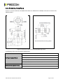
H330 Mini PCIe Hardware User Manual Version: V1.0.5 Date: 2013-09-11 Confidential Material This document contains information highly confidential to Fibocom Wireless Inc. (Fibocom). Fibocom offers this information as a service to its customers, to support application and engineering efforts that use the products designed by Fibocom. The information provided is based upon requirements specifically provided to Fibocom by the customers. All specifications supplied herein are subject to change. Disclosure of this information to other parties is prohibited without the written consent of Fibocom. Copyright Copy, Reproduce, Distribute and/or Edit of this document or part of it as well as utilization of its contents and communication thereof to others without express authorization are prohibited. Offenders will be held liable for payment of damages. All rights created by patent grant or registration of a utility model or design patent are reserved. Copyright ©2013 Fibocom Wireless Inc. All rights reserved. Trademarks Notice The FIBOCOM Logo is registered by Fibocom Wireless Inc. All other product or service names or logos are the property of their respective owners. Copyright ©2013 Fibocom Wireless Inc. All rights reserved. Revision History Version Date Remarks V1.0.0 2012-09-07 Initial Version V1.0.1 2012-12-24 Update product photo V1.0.2 2013-01-09 Update the name of the document; add Reliability Features in specifications V1.0.3 2013-05-02 Update the name of the document, upgrade the manual V1.0.4 2013-05-27 Add Power Sequence description V1.0.5 2013-09-11 Update the name of the document H330 Mini PCIe Hardware User Manual Page 2 of 19 Applicability Table No. Type 1 H330-MiniPCIe-00 2 H330-MiniPCIe-11 H330 Mini PCIe Hardware User Manual Note Page 3 of 19 Contents 1 2 3 4 5 Preface ..................................................................................................................................................................................................... 6 1.1 Scope ......................................................................................................................................................................................... 6 1.2 Standards ................................................................................................................................................................................. 6 Overview ................................................................................................................................................................................................ 7 2.1 Description .............................................................................................................................................................................. 7 2.2 Specifications ......................................................................................................................................................................... 7 Interface Description ......................................................................................................................................................................... 8 3.1 Mini PCI Express Interface ................................................................................................................................................. 8 3.2 Antenna Interface ............................................................................................................................................................... 10 Electrical Features ............................................................................................................................................................................. 11 4.1 Extreme Conditions ........................................................................................................................................................... 11 4.2 Environment Temperature .............................................................................................................................................. 11 4.3 Power Sequence Requirements .................................................................................................................................... 11 4.3.1 Powered-up Time ...................................................................................................................................................... 11 4.3.2 Fall Time ........................................................................................................................................................................ 12 Interface Application Notes........................................................................................................................................................... 13 5.1 5.2 5.3 5.4 USB Interface ........................................................................................................................................................................ 13 5.1.1 USB Interface Description ...................................................................................................................................... 13 5.1.2 USB Interface Application ...................................................................................................................................... 13 USIM Interface...................................................................................................................................................................... 14 5.2.1 USIM Signal Pin Definition ..................................................................................................................................... 14 5.2.2 USIM Interface Application Notes....................................................................................................................... 14 Analog Audio Interface .................................................................................................................................................... 15 5.3.1 Audio Interface Signals Definition...................................................................................................................... 15 5.3.2 Audio Interface Application Note ....................................................................................................................... 15 5.3.3 Audio Channel Output Features.......................................................................................................................... 15 UART ........................................................................................................................................................................................ 15 5.4.1 UART Interface Pin Definition ............................................................................................................................... 15 5.4.2 UART Design ............................................................................................................................................................... 16 5.4.3 Ring Indication ........................................................................................................................................................... 17 5.5 Reset Signal........................................................................................................................................................................... 17 5.6 LPG Signal .............................................................................................................................................................................. 18 H330 Mini PCIe Hardware User Manual Page 4 of 19 5.7 6 W_DISABLE Signal .............................................................................................................................................................. 18 Mechanical Design............................................................................................................................................................................ 19 6.1 Dimensions ........................................................................................................................................................................... 19 H330 Mini PCIe Hardware User Manual Page 5 of 19 1 Preface 1.1 Scope This manual provides the electrical characteristics, RF performance, Structure, Size and Application environment of the H330 Mini PCIe. This document helps developers quickly understand the performance of the H330 Mini PCIe and develop product. 1.2 Standards Mini PCI Express Card Electromechanical Specification Revision 1.0-2003 H330 Mini PCIe Hardware User Manual Page 6 of 19 2 Overview 2.1 Description H330 Mini PCI Express is designed based on FIBOCOM 3G wireless communication module--H330 series, widely used in vehicle and security fields. 2.2 Specifications Product Feature Description Power Supply Input VCC: 3.3V ~ 4.2V (Recommended Voltage:3.5V) Size: 30mm x 50.95 mm x 3.45mm Connector: Mini PCI Express Interface Physical Weight: <10g Operating Temperature: -30°C to +85°C Storage Temperature: -40°C to +85°C Antenna Interface Supports 1 Antenna Interface USB USB2.0 Two UART interfaces: UART 7-lines UART (no DSR) 2-lines UART (only support a few query functions) Reset Signal Audio Interface Other Interfaces External reset signal 1 x Micphone in 1 x Handset out 1 x W_DISABLE 1 x LPG H330 Mini PCIe Hardware User Manual Page 7 of 19 3 Interface Description This chapter describes the external interface and antenna interface of H330 Mini PCIe. 3.1 Mini PCI Express Interface H330 Mini PCIe interface pins are defined as following: Pin# Name I/O Description 1 MICP I Audio channel -MIC signal input + 2 VCC I Power Input 3 MICN I Audio channel -MIC signal input - 4 GND G GND 5 EARP O Audio channel -EAR signal output + 6 NC 7 EARN O Audio channel -EAR signal output - 8 VSIM I USIM Card Power Output 1.8V/3V 9 GND G GND 10 SIMIO I/O USIM Signal Line 11 UART1_RX I UART1 Data Reception 12 SIMCLK O USIM Clock Signal 13 UART1_TX O UART1 Data Transmission 14 SIMRST O USIM Reset Signal 15 GND G GND 16 NC 17 UART1_RI O UART1 ring signal output 18 GND G GND 19 NC 20 W_DISABLE I Low effective, fight mode 21 GND G GND 22 RESET I External reset signal input 23 UART1_CTS I UART1 allow sending data signal input 24 NC 25 UART1_RFR H330 Mini PCIe Hardware User Manual — — — — O UART1 accept ready Page 8 of 19 26 GND G GND 27 GND G GND 28 NC 29 GND G GND 30 NC 31 UART1_DTR O UART1 terminal ready 32 NC 33 UART1_DCD O UART1 carrier detect output 34 GND G GND 35 GND G GND 36 USB_D- I/O USB Signal - 37 GND G GND 38 USB_D+ I/O USB Signal + 39 VCC I Power Input 3.3V-4.2V 40 NC 41 VCC I Power Input 3.3V-4.2V 42 LPG O Network status signal output 43 GND G GND 44 UART2_RX I UART2 Data Reception 45 NC 46 UART2_TX 47 NC — 48 NC — 49 NC — 50 GND 51 NC 52 VCC H330 Mini PCIe Hardware User Manual — — — O G UART2 Data Transmission GND — I Power Input 3.3V-4.2V Page 9 of 19 3.2 Antenna Interface There is an antenna interface in H330 Mini PCIe which uses HIROSE U.FL-R-SMT(01) Connector. As shown in the following figure: Figure 3-1 Dimension and Recommended PCB Mounting Pattern The following table shows the Antenna Performance: Class 4 (2W) : 850/900 MHz, GSM Class 1 (1W) :1800/1900 MHz, GSM Tx Power (Typical Value) Class E2 (0.5W) :850/900 MHz, EDGE Class E2 (0.4W) :1800/1900 MHz, EDGE Class 3 (0.25W) :850/900/1900/2100 MHz, WCDMA Rx Sensitivity (Typical Value) H330 Mini PCIe Hardware User Manual UMTS/HSPA:-109dBm GSM:-108dBm Page 10 of 19 4 Electrical Features This chapter introduces the electrical features of H330 Mini PCIe. 4.1 Extreme Conditions Parameter Desscription Minimum Maximum Unit VCC Module Input Voltage 0 4.2 V VIN IO Input Voltage 0 3.6 V 4.2 Environment Temperature Parameter Minimum Maximum Unit Operating Temperature -30 +85 °C Storage Temperature -40 +85 °C 4.3 Power Sequence Requirements 4.3.1 Powered-up Time The following figure shows the establish time of voltage when powered up: Figure 4-1 Power up Sequence Diagram T s1 Description Requiremetns The time for the power voltage to change from 2.5V to 3.3V lower than 5ms Note: If it takes too long to rise the power voltage , the module may fail to power up. H330 Mini PCIe Hardware User Manual Page 11 of 19 4.3.2 Fall Time The power voltage drops and then rise again, corresponds to the power down time of the module. The following figure shows the time requirements: Figure 4-2 Power off Sequence Diagram T d1 Description Requiremetns The time for the power voltage to change from 3.3V to 2.5V lower than 45ms H330 Mini PCIe Hardware User Manual Page 12 of 19 5 Interface Application Notes 5.1 USB Interface 5.1.1 USB Interface Description H330 Mini PCIe supports USB2.0, compatible with USB1.1, please install the USB driver before you use the USB interface. 5.1.2 USB Interface Application The following figure shows the reference circuit: Figure 5-1 USB Interface Reference Circuit T2 and T3 requires the selected capacitance values lower than 1pF following TVS diode. USB_DP and USB_DM for high-speed differential signal lines, the maximum transfer rate of 480 Mbps, PCB Layout must notice the following requirements: USB_DP and USB_DM should be equal length and as short as possible USB_DP and USB_DMneed GND isolation USB2.0 differential signal line fabric away from the strata nearest the signal layer Good impedance matching, impedance requirement of 90 ohms H330 Mini PCIe Hardware User Manual Page 13 of 19 5.2 USIM Interface 5.2.1 USIM Signal Pin Definition Pin# Name I/O Function Description 8 USIM_VCC O USIMPower Supply Signal 14 USIM_RST O USIM Reset Signal 12 USIM_CLK O USIM Clock Signal 10 USIM_IO I/O USIM Data Signal 5.2.2 USIM Interface Application Notes Recommended USIM Design: Figure 5-2 Recommended USIM Design Note: To improve EMC performance, the SIM card holder should be close to the module. The SIM card signal filter capacitor should be close to the SIM card pin. SIM card signals the need to increase the ESD device (such as TVS diode) protection, ESD devices should be close to the SIM card pin placement. H330 Mini PCIe Hardware User Manual Page 14 of 19 5.3 Analog Audio Interface 5.3.1 Audio Interface Signals Definition H330 Mini PCIe supports 1 input audio channel and 1 audio output channel. Pin# Name I/O Description 7 EAR- O Audio channel headphone signal output - 5 EAR+ O Audio channel headphone signal output + 1 MIC+ I Audio channel MIC input signal + 3 MIC- I Audio channel MIC input signal - 5.3.2 Audio Interface Application Note Audio input and output signal is a differential signal, it has good resistance performance to RF interference, no external audio amplifier is needed when connecting to the handset. The PCB traces requires of long, parallel to the length as short as possible, plus a package deal, best by GND aspects of isolation between the input and output signals. The best audio signal port and ESD protection. 5.3.3 Audio Channel Output Features Differential audio Channel interface is used for handling calls. Table I: MIC input interface level characteristics Parameter Test Condition Bias Voltage Without Load Gain Programable steps 1dB Minimum Typical Maximum Units 2.5 2.6 V 16 dB 0 Design Impedance 2.2 Kohm Table II: The the EAR output interface level characteristics: Parameter Test Conditions Output Voltage Without Load Minimum Typical Maximum Units 1.4 Vpp Design Load Impedance 32 ohm DC Bias Voltage 1 V 5.4 UART 5.4.1 UART Interface Pin Definition H330 Mini PCIe has UART ports: one is 7 wire serial bus interface, and then other is a 2 wire serial bus interface. H330 Mini PCIe Hardware User Manual Page 15 of 19 7 wire serial bus interface (UART1) supports flow control and all the AT commands, it does not support UART1_DSR; users can download software or send/receive AT through UART1. 2 wire serial bus interface (UART2) only supports a few AT Commands. UART1 and UART2 pin definition: UART1 Pin# Pin Name I/O Description 17 UART1_RI O UART1 Ring Indicator 31 UART1_DTR O UART1 DCE Ready 33 UART1_DCD O UART1 Carrier Detect 23 UART1_CTS I UART1 Clear to send 25 UART1_RFR O UART1 Ready to accept 13 UART1_TXD O UART1 Transmitted Data 11 UART1_RXD I UART1 Received Data Pin# Pin Name I/O Description 44 UART2_RXD I UART2 Received Data 46 UART2_TXD O UART2 Transmitted Data UART2 5.4.2 UART Design The following table shows the signal direction when H330 Mini PCIe (DCE) UART1 connects to PC (DTE): Application MCU(DTE) Signal Direction H330 Mini PCIe (DCE) RXD UART1_TXD TXD UART1_RXD RTS UART1_CTS RFR UART1_RFR DTR UART1_DTR RI UART1_RI DCD UART1_DCD H330 Mini PCIe Hardware User Manual Page 16 of 19 The following table shows the signal direction when H330 Mini PCIe (DCE) UART2 connects to PC (DTE): Application MCU(DTE) Signal Direction H330 Mini PCIe (DCE) RXD UART2_TXD TXD UART2_RXD Note: The high level of H330 Mini PCIe’s UART interface is 3.3V. 5.4.3 Ring Indication UART1_R1 is used for indicating incoming call and SMS, sending pulse to host application program. Mode Status No ringing Low level Ringing 1s high level, 1s low level, cycling No message Low level Incoming message 150ms pulse 5.5 Reset Signal H330 Mini PCIe supports external reset; it can restore the module to default settings through Reset signal. When Reset signal is Active Low by 100ms, the module will reset. When users reset the module, PMU inside the module is still on. If the module is connected to PC, you can see PC Virtual port restarts. Note: Reset signal is sensitive; please stay away from radio frequency interference when PCB layout, add debounce capacitor near the module end is recommended. The following table shows the burst timing: Parameter Condition Pulse Width Minimum Value Typical Value Maximum Value Unit 100 300 3000 ms Recommended design: Figure 5-3 Reset Recommended Design H330 Mini PCIe Hardware User Manual Page 17 of 19 5.6 LPG Signal LPG signal description: Status Mode idle(unregistered) 600ms high level, 600ms low level idle(registered) 75ms high level, 3S low level Call low level Data communicating 75ms high level, 75ms low level Sleep high level 5.7 W_DISABLE Signal Module Status W_DISABLE Signal Mode Normal mode high level W_DISABLE high level, module is in normal mode. Fight mode low level W_DISABLE low level, module is in fight mode. H330 Mini PCIe Hardware User Manual Page 18 of 19 6 Mechanical Design 6.1 Dimensions Figure 6-1 Dimensions You can refer to Molex’s Mini PCI Express connector, Model No.: MPC24-52K3311. As shown in the following figure: Figure 6-2 MPC24-52K3311 Connector H330 Mini PCIe Hardware User Manual Page 19 of 19