1
USER MANUAL
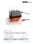
AOS Box Oxygen and Salinity
Web based oxygen and salinity logging - directly to computer
B
27.08.15
Re-approved (ECO-0000743)
EBL
MM
A
08.06.15
Approved
EBL
MM
Rev
Date
Issued by
Approved by
Document no.:
Issued
DC10000882
Document
part no.:
User manual AOS Box Oxygen and Salinity
100001032
Project no.:
86620-01
Document no. DC10000882
Page 1 of 51
For a thorough introduction of Your AKVA product, we ask that
all users read this entire manual. If questions occur, contact us!
The information in this document is subject to change without
notice and should not be construed as a commitment by
AKVA group ASA.
AKVA group ASA assumes no responsibility for any errors that
may appear in this document.
In no event shall AKVA group ASA be liable for incidental or
consequential damages arising from use of this document or of
the software and hardware described in this document.
We reserve all rights in this document and in the information
contained therein. Reproduction, use or disclosure to third
parties without express authority is strictly forbidden.
This document can also be read and downloaded from our web
site, see www.akvagroup.com/products/user-manuals
© 2015 AKVA group ASA (NO)
User manual AOS Box Oxygen and Salinity
Document no. DC10000882
Page 2 of 51
Table of contents
1
Safety ....................................................................................................... 5
1.1
Safety symbols ........................................................................................... 5
1.2
Receiving a new product .............................................................................. 6
1.3
Blind plugs, protection stockings and transportation ........................................ 6
1.4
Disinfecting equipment ................................................................................ 6
1.5
Cables ....................................................................................................... 7
1.6
Bad weather .............................................................................................. 7
2
Information .............................................................................................. 8
2.1
How to use this manual ............................................................................... 9
2.2
About AKVA group ...................................................................................... 10
2.3
About AOS Box........................................................................................... 11
3
Installation ............................................................................................. 14
3.1
Installation instructions .............................................................................. 15
4
Web site - access .................................................................................... 17
5
Web site -use ......................................................................................... 19
5.1
Top functions ............................................................................................. 20
5.2
Overview ................................................................................................... 21
5.3
Details ...................................................................................................... 30
5.4
Export ....................................................................................................... 32
5.5
Position and Direction.................................................................................. 34
6
Storage .................................................................................................. 35
7
Batteries ................................................................................................ 36
7.1
Turn off the AOS Box .................................................................................. 37
7.2
Change batteries ....................................................................................... 37
8
Service and repairs ................................................................................. 40
8.1
Shipment insurance ................................................................................... 40
User manual AOS Box Oxygen and Salinity
Document no. DC10000882
Page 3 of 51
9
Maintenance ........................................................................................... 41
9.1
Cleaning the sensors .................................................................................. 41
9.2
Maintenance registration for AOS Box ........................................................... 42
10
Update AOS Box ...................................................................................... 43
11
Spare parts for the AOS Box .................................................................... 44
12
Frequently asked questions .................................................................... 45
Appendix A - Index .......................................................................................... 46
Appendix B - Deviation form ........................................................................... 47
Appendix C - Notes .......................................................................................... 48
Appendix D - Contact information.................................................................... 50
User manual AOS Box Oxygen and Salinity
Document no. DC10000882
Page 4 of 51
1 Safety
Safety for the users of our products, is top focus when
developing new products and user manuals in AKVA group ASA.
Therefore, we strongly recommend that everyone that is using,
performing repairs, service and maintenance on the product and
also everyone working around the product, reads this entire
manual, and especially this chapter on safety.
This recommendation is based on both personnel safety, as
well the desire to keep the products in order and avoiding any
damages risked if the safety instructions are not followed.
1.1 Safety symbols
The following safety symbols are used in this manual:
Information
Show caution, danger of damaging equipment and mild
injuries to personnel
Danger! Will cause dangerous situations and danger for
personnel
1.1.1 Other symbols used in this manual
Go to or see page or chapter for further instructions or more
information
User manual AOS Box Oxygen and Salinity
Document no. DC10000882
Page 5 of 51
1.2 Receiving a new product
Always make sure that the delivery is complete according to the
service note. If the order is not complete or if any other errors
are discovered, contact AKVA group immediately.
Contact information is found in the back of this manual.
1.3 Blind plugs, protection stockings and transportation
Always keep the blind plugs safe after installation of your AOS
Box. We recommend that all caps are kept in a safe place inside
the barge. The blind plugs need to be quick and easy to locate.
When sensor cables are removed from the AOS Box, due to
service shipment, changing batteries, moving or any other
reason, the blind plugs must be attached to the contacts
immediately.
Protection stockings must cover the sensors at all times when
the sensors are not being used. Keep the stockings in a safe
place, preferably in the same place as the blind plugs.
Avoid low temperatures and mechanical strain, as this will
severely reduce the sensor’s accuracy. Recalibration will be
necessary before use after this kind of treatment.
1.4 Disinfecting equipment
If any of the equipment, cables, ropes or other belonging
equipment is being moved to a new location, it is decreed
by law to disinfect everything to prevent contamination. We
recommend rinsing with fresh water after disinfection, because
the disinfectants are strong chemicals that may damage the
equipments surface materials.
User manual AOS Box Oxygen and Salinity
Document no. DC10000882
Page 6 of 51
1.5 Cables
Avoid twirls in the sensor cables, always coil them carefully.
Make sure that all cables are in order, without tears or damages,
before they are connected to the sensor or the AOS Box. Make
sure that there is no tension to the cable when the sensor is
placed in the water by using the chord anchorage on the
mounting bracket to avoid damages to the cable plugs.
1.6 Bad weather
Always make sure that all of the equipment is ok after bad
weather and storms. Bad weather may loosen the bolts and
twirls in cables and suspensions that may lead to equipment
damages. Therefore, it is important to check that everything is
in order after stormy periods.
If anything is out of order or is damaged, contact AKVA group
immediately. Contact information is found in the back of this
manual.
User manual AOS Box Oxygen and Salinity
Document no. DC10000882
Page 7 of 51
2 Information
This user manual is part of the equipment delivered with AOS
Box. Keep the manual for as long as the sensor unit is in use,
and make sure that all changes to the equipment are being
noted in the back of this manual.
Thank you for choosing AKVA group ASA as supplier for your
sensor equipment. Do not hesitate contacting us for more
information regarding installation, use or maintenance for the
AOS Box or any other AKVA products.
The purpose of this manual is to make the user install, use
and maintain the AOS Box in a safe and economical way. The
manual will show how to install, use and maintain the product,
as well as hopefully answer most day to day questions. If there
is anything relevant this manual does not explain or answer,
please contact us for assistance and help to find a solution to
any problems. Contact the AKVA service department, your
subcontractor, your local AKVA office or our main office in
Norway for assistance and help.
User manual AOS Box Oxygen and Salinity
Document no. DC10000882
Page 8 of 51
2.1 How to use this manual
This manual describes how to install, use and maintain the
AOS Box in the best and safest possible way. This entire manual
must be read and understood by ALL users prior to use of the
product. Site owner and farm manager are responsible for that
all personnel and users know and understand the contents of
this manual.
Before the first chapter, is a table of contents. The headlines
works as links to their respective chapter in the .pdf-file.
Chapter 1 is the most important chapter of this manual,
and includes all safety precautions ensuring personnel and
equipment safety during installation, use and maintenance.
Chapter 2 contains information on AKVA group and the AOS Box,
as well as this manual instruction.
Chapter 3 contains a description to how the AOS Box is being
installed in the cage edge, as well as preparations before this
process. Chapter 4 shows how to access the website, and
chapter 5 is an introduction to how to use the website and how
to read the measurements shown here. Preparations before
storage is explained in chapter 6 and battery change procedure
is described in chapter 7. Chapter 8 includes service, repair and
transportation preparations and precautions, maintenance is
described in chapter 9. If the AOS Box is not prepared for use
with salinity sensor, this can be done as described in chapter 10.
Spare parts overview is found in chapter 11, and answers to
frequently asked questions are found in chapter 12.
Four appendixes are found in the back of the manual: Index,
with links to the rest of the manual in the .pdf-document, a
deviation form for all deviations with the system, pages for notes
about new and extra information are also in the back of the
manual and AKVA contact information.
This entire manual must be read and understood before
use, as well as used as aid during installation, use and
maintenance of the AOS Box
User manual AOS Box Oxygen and Salinity
Document no. DC10000882
Page 9 of 51
2.2 About AKVA group
With four main brands, AKVA group ASA is a world leading
supplier of technical aquaculture equipment. Since 1980 we
have developed and produced fish farming equipment, both for
cages at sea and for land based hatcheries. AKVA represents an
industrial standard, which is presumed to be the turn key to the
future. Research, project management, fast deliveries and
customer follow-up have been our focus to ensure that we
contribute to a positive development within the agriculture
industry. Our goal is to deliver the best possible and most cost
efficient equipment in order to keep preserving sustainable
farming.
We have a wide variety of products, for example: plastic and
steel cages, high pressure washers, net washers, boats, feed
barges, feeding systems, cameras, sensor systems, under water
lighting, software for fish farming and recycling systems.
AKVA has a continuous development of products, and we
continue to improve product safety, functions, range of use
and reliability. The purpose of this manual is to enable users
to install, use and maintain the AOS Box in a safe and economic
way.
All of our equipment is pre-installed, tested and delivered from
our own production department. This means that our customers
have total control over which components you can choose from,
grouping collocation, testing and deliveries. Our production staff
consists of people with great expertise and engagement for
producing the best possible products for you. Having our own
production site gives you excellent service in case something
should go wrong, or if you are in need of any assistance. Our
service staff is available on the telephone or on location in order
to assist you if necessary. Safety, both for users and equipment
is our main focus when developing products and product
manuals.
User manual AOS Box Oxygen and Salinity
Document no. DC10000882
Page 10 of 51
2.3 About AOS Box
The AOS Box, is an independent system for measuring oxygen
levels in the sea water. It is a flexible system that runs on
batteries, and also communicates via Iridium satellite. All
information from the AOS Box is displayed in a user friendly web
site.
The AOS Box is continuously receiving oxygen and temperature
measurements from the sensors. As long as the location has
clear sight to the sky and continuous satellite signal, these
measurements will always be available on the web site.
The delivery is, in accordance to the AOS Box unit with sensors,
a plate bracket for simple installation on the cage rail plus a
protection cap for extra protection during really bad weather.
AOS Box with bracket
User manual AOS Box Oxygen and Salinity
Oxygen sensors
Salinity sensor
Document no. DC10000882
Page 11 of 51
Both salinity and oxygen sensors have three different sensors,
one red, one blue and one green. These colour codes are used to
separate the various sensor depths in and outside the cage,
when using more than one of each kind of sensor type with the
same AOS Box.
Two sensors of the same type and the same colour may not be
used at the same AOS Box, however a blue oxygen sensor may
be used with a blue salinity sensor in the same box. One red,
one blue and one green sensor of one type is also possible to use
with the same AOS Box.
The oxygen sensors are optical sensors, and provide stable
measurements for long periods because of the use of membrane
measuring. The membrane will not be not be expended
providing correct maintenance. Oxygen sensor measures %
saturation and the website shows these values in mg/l based
on a constant salinity value. Default salinity is set to 35ppt,
contact Nortek if this value should be changed to accommodate
the specific locations. See chapter 5.1.3 for how the measured
oxygen values are presented in the graph.
The salinity sensors measure conductivity and temperature in
the area where they are placed. Nortek calculates salinity from
these values, and this is presented in the website. The graphs
shows salinity as ppt per time. See chapter 5.1.7 for how the
measured salinity values are presented in the graph.
User manual AOS Box Oxygen and Salinity
Document no. DC10000882
Page 12 of 51
2.3.1 Technical descriptions
Dimensions AOS Box
- weight: 4,8kg
- dimensions: 270 x 250 x 130mm
Operating voltage
3 batteries, 100Wh alkaline batteries
Environment
Operating temperature: -20°C to +45°C
Technical specifications
Sensor type
Brand
Measuring area
Oxygen sensor
Salinity sensor
Insite IG, Dissolved Oxygen
Model 400
Ponsel CTZN:
Inductive Concuctivity
0-25ppm
0-100mS/cm (conductivity)
0-72ppm (salinity)
Accuracy
1% of read value, or 0.02ppm
Resolution
0.01ppm of read value < 4ppm
~0.1ppm
0.1ppm of read value > 4ppm
Data communication:
Data transference: Iridium
Data presentation:
Internet: http://realfish.akvagroup.com
Contacts
Maximum 3 oxygen sensors may be connected to one AOS Box,
one red, one blue and one green sensor. These will measure
oxygen levels in three different depths where installed.
User manual AOS Box Oxygen and Salinity
Document no. DC10000882
Page 13 of 51
3 Installation
Note the StationID of the AOS Box before using it. This ID
number is found on the inside of the box lid.
Before installing the AOS Box to the cage edge, it has to be
activated. This is done by pressing the ON/OFF-button on the
inside panel of the AOS Box for 2-3 seconds. As the system is
turned on, an orange led-lamp will blink, then turn green and
be lit for about one minute to indicate that the start up was
successful.
Install the AOS Box on the cage edge according to instructions in
chapter 3.1. Use the plate bracket for installation. In particularly
exposed locations, we recommend using extra protection to
ensure that the box stays protected from wind and sea water.
No more than 3 of each sensor may be connected to each AOS
Box at the same time.
AOS Box installation:
- Remove the plastic protection stockings
- Make sure that sensor membranes are intact
- Attach all sensor cables to the bracket chord anchorage
- Make sure that the sensors hang freely in the water to avoid
any mechanical strain caused by strikes or friction
- Write down the AOS Box ID number, which sensors (blue, red
or green) are being used and how deep the sensor is placed
User manual AOS Box Oxygen and Salinity
Document no. DC10000882
Page 14 of 51
3.1 Installation instructions
1 Remove the blind plugs and connect the sensors.
Sensors for salinity and oxygen may be connected to the
three contacts that are closest to the case handle
2 Activate the AOS Box by pressing the ON/OFF-button in the
panel inside the box for 2-3 seconds. The led light will blink
red for one second, then it will turn green and stay lit for
about one minute. This indicates that the box has been
activated properly
3 Open the bracket chord anchorage
4 Lay the case handle down and place the gray protection cap
over the AOS Box (so that it covers the handle)
5 Place the AOS Box with protection cap in the plate bracket,
also shown in the image below. Make sure that the black belt
is placed outside the AOS Box case. Attach sensor cables in
the chord anchorage, close and tighten the bolt
6 Bend any blind plugs and lay them against the chord
anchorage as shown in the image below:
User manual AOS Box Oxygen and Salinity
Document no. DC10000882
Page 15 of 51
7 Fasten the belt around the case, and tighten it properly with
the Velcro
Checklist before taking the AOS Box to the cage:
- the AOS box is activated (turned ON)
- all sensors are connected
- protection cap is placed over the box
- blind plugs connected to unused contacts
- sensor cables fastened in the chord anchorage
- belt properly fastened around the case
- bring strips or straps to attach the bracket
8 Bring enough cable ties or belts long enough to go around the
cage rails and hang the plate bracket on the cage rail, on the
right side of a rail pole. Use the ties or belt to fasten the
bracket to the cage rail:
User manual AOS Box Oxygen and Salinity
Document no. DC10000882
Page 16 of 51
4 Website - access
When the AOS Box is placed in the desired location, the
measurements will be available on line.
The website has this address: http://realfish.akvagroup.com
To access the Realfish oxygen- and salinity-logging website,
contact Nortek and follow the instructions on the next page to
receive access.
User manual AOS Box Oxygen and Salinity
Document no. DC10000882
Page 17 of 51
AOS web access Quick Guide
1 Collect following information:
a The AOS Box ID number
This is found on the inside of the AOS Box lid. This is the
identity of the case and all remaining information is linked
to this ID.
b The company name
This information will appear in the web page
c The location name
This information will appear in the web page
d GPS coordinates for the AOS Box
This information is the basis for placing of the flag in the
first page in the web page
e Descriptions for the sensors (2 or 3 different)
Colour, whether it is in- or outside of the cage and depth.
This information will also appear in the web page, making
it easy to find data for each sensor
2 Send all the information above to: [email protected]
3 Receive user name and password and make sure to save the
e-mail and note the information in an additional safe place
4 Go to: http://realfish.akvagroup.com
5 Type user name and password and click on ‘Log on’
6 The data logging from the registered sensors may start and
seen from anywhere at anytime.
A laminated quick guide similar to this page is found inside the
AOS Box case when delivered
User manual AOS Box Oxygen and Salinity
Document no. DC10000882
Page 18 of 51
5 Web site - use
The start page presents an overview to the regions for your
company and shows geographic placement of your locations in
selected region.
Under each region tab is a map showing all locations registered
in chosen region. The colour codes state oxygen level for the
different AOS Boxes where oxygen sensors are connected:
- Red colour: critical - oxygen level below 60%
- Yellow colour: alarming - oxygen level around 60-75%
- Green colour: ok - oxygen level above 75%
Notifications will show in the interface, however only when the
oxygen levels are critical for one or more AOS Boxes in the
region. Under the regions, locations in the region is listed in their
own banners, and the user may click on these to see the
information from the desired location. The locations may also be
chosen by clicking on their flag.
The AOS AKVA Sensor Buoy user manual contains more
information on the buoy and current measuring. This, and
other AKVA user manuals are found in the AKVA website:
www.akvagroup.com/products/user-manuals
User manual AOS Box Oxygen and Salinity
Document no. DC10000882
Page 19 of 51
5.1 Top functions
In the right side of the blue top part of the website, are four different functions:
Welcome [location name] !
- shows which location is logged on. This is useful for users who
have access to several locations in one log-in
Log Off
- logs off the user and opens the log on page
Manuals
- opens pdf user manuals in the website
Box relocation
- opens a form that must be filled out and sent if and when the
AOS Box is being relocated to a new cage or location:
User manual AOS Box Oxygen and Salinity
Document no. DC10000882
Page 20 of 51
5.2 Overview
This first page of any location shows one of several
measurement results of the chosen sensor in this location:
Read more about Hypoxia by clicking on the blue link between
the oxygen graph and the hypoxia chart.
User manual AOS Box Oxygen and Salinity
Document no. DC10000882
Page 21 of 51
5.2.1 Miniature frames
The miniature frames in the right column of the website show
a simple overview of the measurements, oxygen, salinity and
current wherever these sensors are registered and connected
to the system. Measured values are shown in correct colours,
where for instance green oxygen levels show that everything is
ok at the moment, and yellow levels indicates that something is
wrong and needs special attention right away.
5.2.2 Controller data
Controller data battery level is shown in the right side above the
graphs:
The battery level may also be shown graphically as a function of
the time:
The internal temp. function shows temperature measurements
from the inside of the AOS Box as a function of the time. Contact
AKVA service personnel immediately if unexpected variations in
this temperature is discovered.
User manual AOS Box Oxygen and Salinity
Document no. DC10000882
Page 22 of 51
5.2.3 Comparison
Oxygen level may be shown graphically as mg/l or %, and shows
all measurements as a function of the time. This graph shows
red and blue oxygen sensor measurements in mg/l for selected
time span. Oxygen % is saturation values.
Oxygen levels in the mg/l-graph also shows a red dotted line
(1). This line indicates critical oxygen level. If the graph for
measured oxygen is below this value, site manager or other
responsible personnel must firstly check the sensor and its
membrane. If the sensor is placed inside the cage, sprout
concentration in the net must also be controlled. If sprout is
not the reason for the decreased measurements, contact AKVA
service personnel for further inspection of the problem, and if
possible, use an alternative oxygen sensor to find out if the
levels are too low, or if it is the sensor that causes these
measurements.
In case of too low oxygen levels, take immediate action to keep
the fish from suffering from hypoxia, and stop feeding and any
stress as soon as possible. Read more about hypoxia and how
this effects the fish in chapter 5.2.4.
Sensors may be named after where they are placed. Naming is
done by Nortek before starting to use the sensors.
User manual AOS Box Oxygen and Salinity
Document no. DC10000882
Page 23 of 51
5.2.4 Hypoxia
Hypoxia is graphically represented for one oxygen sensor
(choose colour) at a time. Choose desired sensor in the menu
on the left, and the oxygen values are shown in the graph, as
saturation as a function of the time span. Yellow and red lines
indicates critical values as function of the water temperature.
User manual AOS Box Oxygen and Salinity
Document no. DC10000882
Page 24 of 51
Hypoxia diagram colour coding
All values in the graph are based on general tolerances for post-smolt salmon under 1kg
The stars in the diagram represent measured values from the
three different oxygen sensors (blue, red and green).
When the oxygen level is above the Normoxia-line, when the
Hypoxia grade is 1 or higher, all is ok.
When the oxygen level goes below the Normoxia level, and the
hypoxia level is moderate, between -3 and 1, it is recommended
that feeding is reduced. If the Hypoxia level goes below -3 all
feeding and any other disturbance causing fish stress must be
stopped because the survival of the fish is threatened within this
Hypoxia area.
We strongly recommend that all fish farming sites operates with
at least a 20% Normoxia safety margin, this meaning using an
Hypoxia grade at minimum 2.0.
User manual AOS Box Oxygen and Salinity
Document no. DC10000882
Page 25 of 51
5.2.5 Oxygen and Temperature
This function show two separate graphical measurements;
one for oxygen and one for temperature from one of the used
sensors (red, blue or green sensor) at a time.
The blue graph shows oxygen values as function of time, and
the red graph shows temperature values as function of time.
User manual AOS Box Oxygen and Salinity
Document no. DC10000882
Page 26 of 51
5.2.6 Oxygen min/max
This diagram shows maximum and minimum oxygen
measurements for every third hour. Red line shows the highest
measurement from the three hour period, and the blue line
shows the lowest measurement for the same time interval. This
provides a more accurate overview of the oxygen levels, as it
shows larger time intervals. These measurements are stated as
mg oxygen per litre water, as a function of time.
User manual AOS Box Oxygen and Salinity
Document no. DC10000882
Page 27 of 51
5.2.7 Salinity
This diagram shows measured salinity values from the chosen
salinity sensor as a function of time.
The red line indicates temperature as function of time.
User manual AOS Box Oxygen and Salinity
Document no. DC10000882
Page 28 of 51
5.2.8 Timespan for chart
It is possible to customize time span for all diagrams. Choose
between measurements for the current day, week or specified
from one day to another.
A specific time may be shown in the charts, place the mouse
pointer over desired point in the graph for designated timespan,
and an information box with following information will appear:
- which sensor the graph represents, and where this sensor is
placed
- sensor depth*
- date and exact time
- measured value at the chosen time
The mouse pointer may be moved around over the graph, and
the user may choose which time, within the designated timespan
that should be displayed in the information box.
*Let Nortek know where the sensors are placed before registration in
order to show this information in the information box
5.2.9 Speed and direction
This function shows measured current speed and direction from
three different depths where AOS AKVA Sensor Buoy is installed.
See user manual for Sensor Buoy for more information on
current measuring.
User manual AOS Box Oxygen and Salinity
Document no. DC10000882
Page 29 of 51
5.3 Details
Tables containing measurement details are found under the
Details tab.
At the top, registered information about the AOS Box is found,
hereunder Station ID, serial number and firmware.
When the battery indicator turns yellow, new batteries must be
ordered. This is easily done by clicking the Order batteries-link.
This opens a new page with a order form that must be filled in,
and the batteries will be sent from Nortek to the location address
shortly.
User manual AOS Box Oxygen and Salinity
Document no. DC10000882
Page 30 of 51
The Oxygen sensor table shows oxygen measurements in both
% and mg/l, as well as temperature for the same timestamps.
(Green sensor is not connected in the example above)
Salinity sensor measurements table shows salinity in ppt and
conductivity (mS/cm), as well as temperature for the same
timestamps.
The Current table shows current measurements if an AOS AKVA
Sensor Buoy is installed in the location. Current directions
appear both in the table as well as graphically in the compass.
This way, the current directions may easily be compared.
Current speeds are shown in the table.
Read more about the Sensor Buoy and current measurements
in this product’s own user manual. This, and other user manuals
are found in www.akvagroup.com/products/user-manuals
User manual AOS Box Oxygen and Salinity
Document no. DC10000882
Page 31 of 51
The Controller table shows battery status for the AOS Box, as
well as temperature from inside the box. All values relates to the
same timestamps.
The AOS Box’s GPS Positions are shown in the bottom table for
the desired timestamps.
User manual AOS Box Oxygen and Salinity
Document no. DC10000882
Page 32 of 51
5.4 Export
Data saved in Realfish may be exported to a computer for
historical data back-up and possibility of printing reports.
This makes it possible to process the information, and storing
this in paper format if this is desired.
Choose desired time interval, click desired Download button,
choose if and where the file should be saved, or choose open.
The document will open automatically in Microsoft Excel if this
program is installed on the computer.
User manual AOS Box Oxygen and Salinity
Document no. DC10000882
Page 33 of 51
5.5 Position and Direction
Position diagram shows placement of the sensor buoy
(measuring currents) in the map (GPS-position), measured
direction as well as current speed at the chosen time.
The points in the chart are created as a function of north-east
coordinates for the three different depths (divided by colour).
For each measurement in the period of time, one point is added
to the diagram as a north-east based value. This provides a
“cloud” of points, showing how the current measurements are
scattered, and showing how many of the measurements are
north-eastern. It is possible to space out one of the
measurements, by placing the mouse pointer over the
description of the deep (in the top right corner of the chart).
User manual AOS Box Oxygen and Salinity
Document no. DC10000882
Page 34 of 51
6 Storage
Make sure that the AOS Box is turned off before storing it. To
shut the box down, press the ON/OFF button found inside the
box panel for about 10 seconds.
The sensors need to be stored so that they are protected from
random and possible careless handling, always use the
protection stockings over the sensors whenever they are not
being used. This will reduce the risk of mechanical damages.
The sensors must not be exposed to cold temperatures due to
calibration reasons.
User manual AOS Box Oxygen and Salinity
Document no. DC10000882
Page 35 of 51
7 Batteries
The system is delivered with three 100Wh alkaline batteries
(none rechargeable) that should provide the system with
continuous power for estimated period of 4 months. How long
the batteries will last will vary with temperature and the location
Iridium-signals. The web site will indicate status for the batteries
at all times. When the indicator turns red, this indicates that the
batteries must be changed.
The blind plugs must be attached to the AOS Box contacts
whenever the sensors are not connected to the box. The plugs
protect the contacts from corrosion and prevents electric short
circuit. Do not remove the blind plugs until the sensor cables are
going to be reconnected to the AOS Box.
The batteries in the AOS Box must only be changed
indoors
Immediately after the sensors are disconnected from
the box, the blind plugs must be attached to the AOS
Box contacts. The contacts must never ever be exposed
to seawater
Take extra care of the panel bolts during battery change
User manual AOS Box Oxygen and Salinity
Document no. DC10000882
Page 36 of 51
7.1 Turn off the AOS box
When sending the AOS Box to service, changing batteries or
moving it for any other reason, the box must be turned off.
1 Take up the sensors out from the water, and bring the AOS
Box with sensors indoors
2 Disconnect sensors and replace the them with blind plugs.
Put the sensor protecting stockings on the sensors and place
them somewhere safe and out of the way of personnel
3 Wipe off any water residues from the outside of the box
4 Open the box and turn the system off
7.2 Change batteries
1 Turn off the AOS Box as instructed above (chapter 7.1)
2 Remove all the 10 bolts in the panel
Take good care of the bolts during the battery change
3 Flip the panel to the left and lean it over the edge if the box so
that it stands steadily against the antennas on the side of the
box. Make sure that none of the wires are pulled out
during this process
User manual AOS Box Oxygen and Salinity
Document no. DC10000882
Page 37 of 51
4 Remove the batteries one by one and pull out the contacts
from each battery
5 Notice how the batteries are placed in the box and place the
new batteries in the same position as the old ones.
Re-connect the wires before placing the batteries in the box
All batteries have to be changed at the same time!
6 Check that all connections are in place according to the
printed card
7 Flip the panel carefully back into place and make sure that
none of the wires are caught between the panel and the box
Make sure that no wires are placed on top of the
batteries, nor along the gaskets
User manual AOS Box Oxygen and Salinity
Document no. DC10000882
Page 38 of 51
8 Fasten and tighten all 10 bolts and turn the system back on as
described in chapter 3
9 Close the AOS Box properly, remove stockings and connect
sensor cables, then bring the system back to the location.
Fasten the AOS Box properly to the bracket on the cage edge
as described in chapter 3.1.
User manual AOS Box Oxygen and Salinity
Document no. DC10000882
Page 39 of 51
8 Service and repairs
Before sending the AOS Box to AKVA group via Nortek AS for
service or repairs, contact us via e-mail and receive a RMAnumber. RMA is a reference number needed for us to provide
fast and problem free handling of your shipment. Contact
information is found in the back of this manual.
Information that must follow any shipments:
- RMA number
- AOS Box Station ID (found inside the AOS Box lid)
- Company name
- Location name
- Contact person, location
- Delivery address, location
- Invoice address
- Phone number and e-mail address for Site manager
8.1 Shipment insurance
Shipment insurance for repair shipments are not covered by
AKVA group. Make sure that the equipment is properly covered
by Your insurance. AKVA group is not responsible for direct costs
or costs from consequential damages when equipment is lost or
destroyed during transport. Shipment insurance back to
customer after maintenance or repairs is covered by Nortek, and
will be invoiced by AKVA group along with work and shipment
costs. Transport and shipment to customer insurance regarding
warranty repairs, will be covered by Nortek.
User manual AOS Box Oxygen and Salinity
Document no. DC10000882
Page 40 of 51
9 Maintenance
9.1 Cleaning the sensors
Be aware of that sprout on the oxygen sensors may affect the
measurement accuracy.
•
sprout may cause average values to vary from normal, and
most often the value will decrease massively
•
abnormal variations between measurements may occur
- large variations from one hour to another
- large variations from day- to night-time
Net sprout will affect the measurements inside the cage.
Regular control of the net with camera, and following cleaning
when necessary is therefore recommended.
This will normally be a bigger issue in the algae growth is at
its most, during the warmer seasons. In these periods, it is
necessary to control and clean the net and sensors more often.
Clean the sensors carefully with a soft sponge, cloth or brush,
for instance a toothbrush that will fit perfectly in the salinity
sensor measurement opening.
If the oxygen sensor membrane is broken after excessive or
incorrect cleaning, it needs to be sent to the producer for change
and recalibrated.
Do not use any sharp or hard tools for cleaning. This
may cause irreparable damages to the sensor membrane
Prior to cleaning the net, all sensors must be taken out of the
water, both the ones placed inside as well as outside of the net.
All sensor cables are connected at the cage edge, and are all at
risk of getting hooked into the net cleaner if they hang freely
during the cleaning process.
Take sensors out of the water prior to net cleaning
User manual AOS Box Oxygen and Salinity
Document no. DC10000882
Page 41 of 51
9.2 Maintenance registration for AOS Box
Make copies of this form before filling anything out
Date
Parameter
Next
Sign.
maintenance
User manual AOS Box Oxygen and Salinity
Document no. DC10000882
Page 42 of 51
10 Update AOS Box
In order to use salinity sensors with the AOS Box, the software
needs to be updated. This is done by connecting the AOS Box to
a PC using the mini USB cable and the USB gate in the panel
inside the box.
Contact Nortek to receive access to AOS Firmware Upgrader:
After the upgrade, the box requires configuration. Contact
Nortek once again and they will perform this configuration.
Contact information Nortek:
- E-mail: [email protected]
- Phone: 67 17 45 00
AOS Box without USB-port in the panel inside the box can not be
upgraded to salinity use. These can only measure currents and
oxygen.
User manual AOS Box Oxygen and Salinity
Document no. DC10000882
Page 43 of 51
10 Spare parts for AOS Box
For supplement orders of sensors, use these item numbers:
Sensor
Oxygen
Salinity
Red
10001601
10001604
Blue
10001602
10001605
Green
10001603
10001606
For supplement orders of sensor cables:
Length
Oxygen sensor
Salinity sensor
20 feet
(6m)
10001166
10001207
33 feet
(10m)
10001515
10001367
82 feet
(25m)
10001387
10001516
164 feet
(50m)
10000615
10001208
246 feet
(75m)
10000616
10001209
328 feet (100m)
10000617
10001210
All sensors are delivered with cable and plug.
AOS Box batteries, item no. 0105891
Order new batteries from the website, see chapter 5.2 for
instructions
Back up blind plugs may be ordered with the following item no.:
- 5 pin blind plug: 10001520 (oxygen + salinity connections)
- 8 pin blind plug: 10001239 (Doppler connection)
User manual AOS Box Oxygen and Salinity
Document no. DC10000882
Page 44 of 51
12 Frequently asked questions
Most problems that occur with the AOS Box are caused by simple
issues. Therefore, we ask you to please check the following if
any problems occur with the AOS Box before contacting AKVA
service personnel:
1 Is the cable in order? Cross-check by switching the cables:
- if a cable is broken, it will not measure from any of the
contacts
- if the cable measures from any of the other contacts, this
may indicate problems with the contact
2 Have the batteries got run down?
(check the web site, see chapter 5.2.2)
3 Are all wires in order and connected properly?
4 Does the AOS antenna have clear sight towards the sky?
5 Are the sensor or the cage net covered with sprout?
User manual AOS Box Oxygen and Salinity
Document no. DC10000882
Page 45 of 51
Appendix A - Index
A
N
accuracy 6, 13, 41
new location 29
activate 14-16
notifications 17
B
O
battery 6, 9, 11, 13, 22, 30, 32, 36, 37
ON/OFF-button 11, 12, 23
bolts 7, 15, 36, 37, 39
oxygen level 9, 17-19, 21, 29
C
P
chord anchorage 7, 14-16
panel 11, 12, 25, 28
contacts 13, 15, 16, 36, 38, 45
protection stocking 5, 11, 12
current 19-21
R
E
resolution 10
exporting data 22
RMA 28
F
S
fastening bracket 6, 9, 11-13
saturation 19, 21
shipment 5, 28
I
sprout 19, 29
ID number 12, 16
Iridium 9, 10, 24
T
temperature 5, 9, 10, 19, 21, 23, 24
L
time intervals 20, 22
log on 16
timespan 20
M
transport 5, 24, 28
measurement 9, 15, 17-21, 29
W
mechanical strain 6, 11
warranty 28
web site 9, 15, 17, 24
User manual AOS Box Oxygen and Salinity
Document no. DC10000882
Page 46 of 51
of 51
Appendix B - Deviation form
Make copies of this deviation form before filling anything in
Deviation control nr.:
Unit:
Producer:
Prod.no.:
Purchase year:
Deviation description:
Follow up proposition:
Date and signature, declarer:
Follow up directed:
Status:
New action for deviation no.:
Date and signature, follow up:
User manual AOS Box Oxygen and Salinity
Document no. DC10000882
Page 47 of 51
of 51
Appendix C - Notes
User manual AOS Box Oxygen and Salinity
Document no. DC10000882
Page 48 of 51
of 51
User manual AOS Box Oxygen and Salinity
Document no. DC10000882
Page 49 of 51
of 51
Appendix D - Contact information
NORWAY - AKVA group ASA
SWEEDEN
Head Office
AKVA group - Agent: Modus Trading AB
Nordlysveien 4
Färjegårdarne 7
PO. Box 271
78461 Borlänge, Sweden
N-4340 Bryne
t. +46 - (0)243 883 22
Norway
f. +46 - (0)243 21 17 78
tel. +47 - 51 77 85 00
[email protected]
fax. +47 - 51 77 85 01
Support Hardware and AKVAconnect
FINLAND
tel. + 47 - 51 77 85 03
AKVA group - Agent: OY MG Trading AB
[email protected]
Ivisnäsplanen 2E
SF-02260 Esbo, Finland
Support Fishtalk
tel. +47 - 73 84 28 20
t. +358 - 9867 68422
f. +358 - 9867 68420
[email protected]
ICELAND
AKVA group - Agent
DENMARK
Wise lausnir ehf
AKVA group Denmark AS (Land Based)
Borgartun 26, 105 Reykjavik, Iceland
Bødkervej 7A, 1.
t. + 354 545 3200
7000 Fredericia, Denmark
f. +354 545 3232
t. +45 7551 3211
f. +45 7551 4211
UK (SCOTLAND)
AKVA group Denmark AS (Land based)
Rosklidevej 342, Building 2
2630 Taastrup, Denmark
t. +47 7551 3211
AKVA group Scotland Ltd.
36F Shore Street
Inverness, Scotland, UK
IV1 1NF
t. +44 (0)1463 221 444
f. +44 (0)1463 223 535
User manual AOS Box Oxygen and Salinity
Document no. DC10000882
Page 50 of 51
of 51
GREECE
CANADA
Akvasmart/Fishtalk - Agent:
AKVA group North America Inc.
Zellas Trading Company
1495 Baikie Road, Campbell River
Dodekanisou Str., GR-174 56
BC, V9W 1R9 Canada
Alimos, Athens, GREECE
t. +1 - 250-286-8802
t. +30 - 210 7014881
f. +1 - 250-286-8805
f. +30 - 210 7012666
[email protected]
AKVA group North America Inc.
5251 Duke Street, Suite 606, Duke Tower,
Scotia Square
TURKEY
AKVA group Kültür
Balıkçılığı Ekipmanları Ltd. Şti.
Halifax, NS, B3J 1P3 Canada
t. +1-902-482-2663
f. +1 - 902-405-3373
Yeni Küçük Sanayi Sitesi No:1-C19 Baharlı Köyü
48200 Milas, Muğla, TURKEY
t. +90 - 252 - 374 - 6434
f. +90 - 252 - 374 - 6432
CHILE
AKVA group Chile
Ruta 5 Sur Km.
1030, Puerto Montt, Chile
t. +56 - 65 250250
TUNISIE
f. +56 - 65 257119
AKVA group - Agent: Sociètè Mèditerranèenne
d`Etudes et Conseils
72, Avenue Habib Bourguiba
2080 Ariana, Tunisie
t. +216 71 700 453
f. +216 71 700 297
AUSTRALIA
AKVA group Australasia
t. +61 400 167 188
[email protected]
[email protected]
User manual AOS Box Oxygen and Salinity
Document no. DC10000882
Page 51 of 51