1
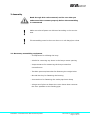
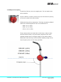
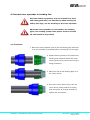
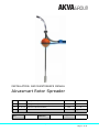
INSTALLATION- AND MAINTENANCE MANUAL
Akvasmart Rotor Spreader
C
04.12.15
Re-Approved (ECO-0000850)
EBL
IL
B
31.08.15
Re-Approved (ECO-0000784)
EBL
IL
A
17.10.14
Approved (ECO-0000592)
EBL
IL
Rev
Date
Issued by
Approved by
Document
no.:
Issued
DC10000895
Document
part no.:
Installation- and Maintenance Manual Rotor Spreader
10001171
Project no.:
88072-01
Document no. DC10000895
Page 1 of 30
For a thorough introduction of Your AKVA product, we ask that
all users read this entire manual. If questions occur, contact us!
The information in this document is subject to change without
notice and should not be construed as a commitment by
AKVA group ASA.
AKVA group ASA assumes no responsibility for any errors that
may appear in this document.
In no event shall AKVA group ASA be liable for incidental or
consequential damages arising from use of this document or of
the software and hardware described in this document.
We reserve all rights in this document and in the information
contained therein. Reproduction, use or disclosure to third
parties without express authority is strictly forbidden.
This document can also be read and downloaded from our web
site, see www.akvagroup.com/products/user-manuals
© 2015 AKVA group ASA (NO)
Installation- and Maintenance Manual Rotor Spreader
Document no. DC10000895
Page 2 of 30
Table of contents
1
Safety..........................................................................................................4
1.1
Safety symbols .............................................................................................4
1.2
General ........................................................................................................5
1.3
Personnel safety ...........................................................................................6
1.4
Equipment safety ..........................................................................................6
2
Information ................................................................................................7
2.1
How to use this manual .................................................................................8
2.2
About AKVA group .........................................................................................9
2.3
About Akvasmart Rotor Spreader ................................................................... 10
3
Assembly ..................................................................................................11
3.1
Necessary assembling equipment ................................................................. 11
3.2
Buoy for buoyancy ...................................................................................... 12
3.3
Weight for stability ..................................................................................... 13
3.4
Bearing for even rotation ............................................................................. 14
3.5
Outlet pipe ................................................................................................ 14
3.6
Ready for connecting to the feeding system ................................................... 14
4
Connect rotor spreader to feeding line .....................................................15
4.1
Procedure .................................................................................................. 15
4.2
Adjusting the rotor spreader ........................................................................ 16
5
Placing Akvasmart Rotor Spreader in the cage .........................................15
5.1
Procedure .................................................................................................. 15
6
Maintenance............................................................................................. 18
6.1
Regular maintenance ................................................................................... 18
6.2
Blockages inside the feeding system .............................................................. 19
6.3
Cleaning bearings ........................................................................................ 23
6.4
Spare parts................................................................................................. 23
6.5
Registration of maintenance ......................................................................... 24
Appendix A - Index ..........................................................................................25
Appendix B - Deviation form ............................................................................26
Appendix C - Notes ..........................................................................................27
Appendix D - Contact information.....................................................................29
Installation- and Maintenance Manual Rotor Spreader
Document no. DC10000895
Page 3 of 30
1 Safety
Safety for the users of our products, is main focus when
developing new products and user manuals in AKVA group.
Therefore, we strongly recommend that everyone that is going
to be using it, carry out repairs, service and maintenance on
the product, as well as everyone working in the area where the
product is installed or being used, reads this entire manual, and
especially this safety chapter.
This recommendation is based on both personnel safety, as
well the desire to keep the products in order as long as possible,
by avoiding any damages risked if the safety instructions are not
followed.
1.1 Safety symbols
These safety symbols are used in this manual:
Information
Show caution, danger of minor personnel injuries and
damages to equipment
Warning - may cause personnel injuries
Danger! - Will cause dangerous situations and danger for
personnel
1.1.1 Other symbols used in this manual
Go to or see page or chapter for further instructions or more
information
Installation- and Maintenance Manual Rotor Spreader
Document no. DC10000895
Page 4 of 30
1.2 General
This manual describes how to install and maintain the Akvasmart
Rotor Spreader. AKVA service personnel will execute any
remaining tasks. Only when written consent from an AKVA
employee exists, is it possible for others to execute these.
1.3 Personnel safety
Farm owner where Akvasmart Rotor Spreaders are installed, is
responsible for complying applicable safety laws and regulations
in the current country, such as correctly designed and installed
safety devices. Farm owner is also responsible for that all
employees are informed about and understand the content of
this manual. All users of this product must know about:
- How the Akvasmart Rotor Spreader works with the rest of the
feeding system
- Which safety considerations that must be taken regarding
installation, use, maintenance and other task with and around
the rotor spreader
- How the Akvasmart Rotor Spreader works and how to use it
- How to maintain the Akvasmart Rotor Spreader according to
procedures described in this manual.
Owner and farm manager are responsible for that all personnel
working with or around the Akvasmart RotorSpreader read and
understand the entire content of this manual, especially dangers
and consequences related to misuse.
To prevent personnel injuries and equipment damages during
installation, maintenance and repairing processes, it is crucial
that all instructions provided in this manual are followed. All
applicable safety laws and regulations in the country where the
equipment is installed must be complied.
Installation- and Maintenance Manual Rotor Spreader
Document no. DC10000895
Page 5 of 30
Personal safety equipment, such as antiskid foot wear and
floating garments, are mandatory to wear when working on and
by the cage, for instance when working on the rotor spreader.
Troubleshooting must, on some occasions, be carried out with
power turned on. At such occasions, it is very important that all
personnel staying around this (and other rotating equipment),
wears appropriate safety gear, minimum helmet and floating
garments. To ensure safe operations, perform all tasks according
to descriptions in this manual.
As a main rule power for the entire feeding system must be
turned off and secured in off position during any work, such as
installation, maintenance and repairs.
1.4 Equipment safety
Check all equipment after periods of bad weather for damages.
Make sure that all suspensions are intact, that surrounding
equipment are ok, check nets especially. If any damages have
occurred, they must be repaired at once, contact AKVA group for
assistance if needed.
Make sure that all parts are delivered according to the service
note. If the order is not complete, or if any defects are
discovered, contact AKVA immediately.
If any of the equipment, ropes or other belonging parts are
being moved to a new location, it is decreed by law to disinfect
everything to prevent contamination. We recommend rinsing
with fresh water after disinfection, because the disinfectants are
strong chemicals that may damage the surface materials.
Contact information is found in the back of this manual.
Installation- and Maintenance Manual Rotor Spreader
Document no. DC10000895
Page 6 of 30
2 Introduction
This user manual is part of the equipment delivered with
Akvasmart Rotor Spreader. Keep the manual for as long as the
rotor spreader is used, and make sure that all changes to the
equipment are being noted in the back of this manual.
Thank you for choosing AKVA group ASA as supplier for your
feed spreader. Do not hesitate contacting us for more
information regarding installation, use or maintenance for
Akvasmart Rotor Spreader or any other AKVA product.
The purpose of this manual is to make the user install and
maintain Akvasmart Rotor Spreader in a safe and economical
way. The manual will show how to install and maintain the
product, as well as hopefully answer most day to day questions.
If there is anything relevant this manual does not explain or
answer, please contact us for assistance and help to find a
solution to any problems. Contact the AKVA service department,
your subcontractor, your local AKVA office or our main office in
Norway for assistance and help.
Installation- and Maintenance Manual Rotor Spreader
Document no. DC10000895
Page 7 of 30
2.1 How to use this manual
This manual describes how to install and maintain the Akvasmart
Rotor Spreader in the best and safest possible way. This entire
manual must be read and understood by ALL users prior to
installation of the product. Site owner and farm manager are
responsible for training all personnel and users know and make
sure they all understand the contents of this manual.
Before the first chapter, is the table of contents. The headlines
works as links to their respective chapter in the .pdf-file.
Chapter 1 is the most important chapter of this manual, and
includes safety precautions ensuring safest possible use.
Chapter 2 contains information on AKVA group and Akvasmart
Rotor Spreader, as well as this manual instruction.
Chapter 3 describes assembling of the Rotor Spreader, and
how to connect to the feed system is explained in chapter 4.
Installation of the Rotor Spreader inside a cage is described in
chapter 5, and maintenance and safety regulations for searching
for and removing of pellet blockages inside the rotor spreader
are described in chapter 6.
Four appendixes are found in the back of the manual: Index,
with links to the rest of the manual in the .pdf-document, a
deviation form for all deviations with the system, pages for notes
about new and extra information are also in the back of the
manual and AKVA contact information.
This entire manual must be read and understood, as
well as used as aid during installation and maintenance
of the Akvasmart Rotor Spreader
Installation- and Maintenance Manual Rotor Spreader
Document no. DC10000895
Page 8 of 30
2.2 About AKVA group
With four main brands, AKVA group ASA is a world leading
supplier of technical aquaculture equipment. Since 1980 we
have developed and produced fish farming equipment, both for
cages at sea and for land based hatcheries. AKVA represents an
industrial standard, which is presumed to be the turn key to the
future. Research, project management, fast deliveries and
customer follow-up have been our focus to ensure that we
contribute to a positive development within the agriculture
industry. Our goal is to deliver the best possible and most cost
efficient equipment in order to keep preserving sustainable
farming.
We have a wide variety of products, for example: plastic and
steel cages, high pressure washers, net washers, boats, feed
barges, feeding systems, cameras, sensor systems, under water
lighting, software for fish farming and recycling systems.
AKVA has a continuous development of products, and we
continue to improve product safety, functions, range of use
and reliability. The purpose of this manual is to enable users
to install and maintain Akvasmart Rotor Spreader in a safe and
economic way.
All of our equipment is pre-installed, tested and delivered from
our own production department. This means that our customers
have total control over which components you can choose from,
grouping collocation, testing and deliveries. Our production staff
consists of people with great expertise and engagement for
producing the best possible products. Having our own production
site provides excellent service in case something should go
wrong, or if assistance is required. Our service staff is available
over telephone or on location to assist whenever necessary.
Safety, both for users and equipment is main focus when AKVA
group develops products and product manuals.
Installation- and Maintenance Manual Rotor Spreader
Document no. DC10000895
Page 9 of 30
2.3 About Akvasmart Rotor Spreader
One of the most important factors for gentle feed handling is
regulating transport air speed. “Speed kills” also when it comes
to feed systems, and reduction of transport air speed provides
significant reduction in feed dust and pellet breakage. Using
the Air Control System combined with the highly effective, low
friction start Rotor Spreader allows reduction in air speed while
still getting excellent feed spread.
The unique Rotor Spreader is designed to provide excellent feed
spread in cages. All our models have adjustable light weight
aluminium rotor pipes that allow for lower air speed for start up
and rotation. This means less dust and breakage, power
consumption, back pressure, air temperature, noise and wear
and tear on the feed pipes.
Our unique ventilated Zenon bearing requires no regular cleaning and does not corrode. Due to its light displacement and low
point of gravity versus centre of buoyancy, the Rotor Spreader is
very stable in rough seas.
Technical specifications:
Installation- and Maintenance Manual Rotor Spreader
Document no. DC10000895
Page 10 of 30
3 Assembly
Read through this entire manual, and be sure that you
understand the contents properly before the assembling
is commenced
Make sure that all parts are delivered according to the service
note
The assembling must be done on shore or in the barge/on a boat
3.1 Necessary assembling equipment
- A compressor for inflating the buoy
- A knife for removing any burrs in the buoys center opening
- A tape measure for measuring the buoys centerline
circumference
- Two M10 spanners/wrenches for fastening the weight bolts
- One M6 hex key for fastening the bearing
- A screwdriver for fastening the outlet pipe hose clamp
- A large set of pliers to fasten the union house that connects
the rotor spreader to the feeding pipe
Installation- and Maintenance Manual Rotor Spreader
Document no. DC10000895
Page 11 of 30
3.2 Buoy for buoyancy
Thread the flat buoy onto the weight pole. The air nipple must
point upwards.
If this is difficult, carefully remove any burrs around the opening
of the buoy center hole with a knife.
Inflate the buoy with a compressor. The buoy is properly inflated
when the centerline/split-line has a circumference of:
- CF63: 50” (1.27m)
- CF90: 50” (1.27m)
- CF110: 60” (1,52m)
These values make sure that 50% of the buoy is above water
and 50% below water, only with these proportions the rotor
spreader stands with a 90 degree angle in the water surface.
Remember that the buoy and the bottom stability weight is the
only buoyancy force of the rotary spreader.
Installation- and Maintenance Manual Rotor Spreader
Document no. DC10000895
Page 12 of 30
3.3 Weight for stability
The Akvasmart Rotor Spreader may be delivered with stability
weight cover with rounded edges to protect the net from the
weight. This cover is assembled before the stability weight, or
any time after, but then the weight needs to be removed first.
3.3.1 Assembling stability weight (without protection
cover)
1 Align the stability weight hole with the weight pole hole
2 Insert the M10x80 Allen bolt
3 Lock with the M10 nut.
3.3.2 Assembling stability weight with protection cover
1 Tread the protection cover far up the rotor spreader pole
2 Follow the instructions in chapter 3.3.1 (above)
3 Place the lid (the green part in the image below) in the
opening of the bottom of the protection cover
4 Fasten the lid by inserting the lock ring (the red part in the
image below).
Installation- and Maintenance Manual Rotor Spreader
Document no. DC10000895
Page 13 of 30
3.4 Bearing for even rotation
1 Attach all 3 M8 Allen screws before tightening
2 Tighten the bolts one by one to maximum 6Nm.
If these are overtightened, the bearing house
will bend and the bearing will become useless.
3.5 Outlet pipe
Use the hose clamp to lock the outlet pipe in desired position.
The spread area is adjusted by the outlet pipe:
- pointing it downwards reduces the spread area
- pointing it upwards increases the spread area
3.6 Ready for connecting to the feeding system
The Akvasmart Rotor Spreader
is now ready to be taken out to
the cage edge.
Continue to chapter 4 for instructions
on how to connect it to the feeding
pipes and the rest of the feeding
system.
Installation- and Maintenance Manual Rotor Spreader
Document no. DC10000895
Page 14 of 30
4 Connect rotor spreader to feeding line
Personal safety equipment, such as antiskid foot wear
and safety garments, are mandatory when working on
and by the cage, ans for working on the rotor spreader
When the rotor spreader is connected to the feeding
pipes, the feeding system main power must be turned
off and locked in off position
4.1 Procedure
1 Place the rotor spreader next to the PE feeding pipe and hold
it up as vertically as possible before connecting it to the pipe
2 Smear siliconc grease on the end of the
feeding pipe end and inside the union
house (green color) where the O-ring is
being pressed in
3 Place the end of the feeding pipe in to
the union house
4 Screw the union (blue color) into the
union house using hand force firstly,
then use pliers or a large spanner to
tighten the connection.
Installation- and Maintenance Manual Rotor Spreader
Document no. DC10000895
Page 15 of 30
4.2 Adjusting the rotor spreader
When the rotor spreader is dropped into the water, it will not
align itself in the water, because of its light weight. The installer
needs to proceed tentatively and adjust little by little to make
the spreader angular to the water surface and by this, achieve
best possible use for the rotor spreader.
After the rotor spreader is connected to the feeding pipe, it must
be placed in the water and left there for a while to adjust.
If the rotor spreader does not stand vertically, it must be
adjusted further.
Take it out from the water, and either:
- twist the union and twist the rotor spreader, or
- pull the weight in the bottom of the pole the opposite direction
of the displacement
Repeat this process until the rotor spreader stays vertical in the
water.
Installation- and Maintenance Manual Rotor Spreader
Document no. DC10000895
Page 16 of 30
5 Placing Akvasmart Rotor Spreader in the cage
To obtain best possible spread of pellets inside the cage, we
recommend placing the rotor spreader as centered as possible
inside the cage ring or edges.
Three ropes fastened to the rotor spreader are used to keep it in
place inside the cage. The ropes are not for holding the rotor
spreader vertical, the buoy and the stability weight does this.
5.1 Procedure
1 Tie each rope to safety hooks
2 Attach the safety hooks to the rotor spreader as shown
in the figure to the left
3 Using the ropes, bring the rotor spreader to desired
position
4 Fasten the ropes to the cage rail as shown in the figure:
We recommend using a rolling hitch knot when tying the ropes
to the cage edge.
Installation- and Maintenance Manual Rotor Spreader
Document no. DC10000895
Page 17 of 30
6 Maintenance
Remember to always turn the main power switch off and
secure in locked position before any work done with the
rotor spreader
Personal safety equipment, such as antiskid foot wear
and safety garments, are mandatory when working on
and by the cage, for instance when working on the rotor
spreader
Regular maintenance on the rotor spreader bearing is important
in order to maintain an even rotation during feeding.
AKVA group recommend bearing inspection minimum every
sixth month. Clean and change when required.
Contact AKVA group Service if any questions occur that is not
answered in this manual, or if it is desired that AKVA service
personnel should perform maintenance to the rotor spreader
or any other AKVA products.
6.1 Regular maintenance
Control the rotor spreader bearing every sixth month to make
sure that it is not dirty or have contaminations inside. The
bearing must also be controlled if it seems to be rotating slower
than usually when all other parts of the feeding system are in
order, as this may indicate that the bearing is contaminated.
Follow instructions in chapter 6.3 for correct control, and clean
or change bearing when required.
Register all performed maintenance in the form in chapter 6.5.
Remember to make copies of this form before filling anything
out.
Installation- and Maintenance Manual Rotor Spreader
Document no. DC10000895
Page 18 of 30
6.2 Blockages inside the feeding system
If pellets are sent out from the dosers on the feeding line, but
none come out of the rotor spreader outlet, when the feeding
software is set to feed, this may indicate a blockage inside the
system.
A blockage inside the feeding system will build up a severe
internal air pressure inside this system. This pressure will not
be set off when turning off the blower, and when the blockage
is released, the pressured air will bring the pellets the easiest
way out - through the rotor spreader outlet, with risk of creating
a dangerous situation for persons staying around the rotor
spreader. The compressed pressure must be neutralized as
described in this chapter to avoid injuring personnel.
If no other causes for air and pellet stop are found in the software or other equipment, pipes, hoses and rotor spreader have
to be controlled for pellet blockages as instructed in this chapter.
When searching for blockages inside the rotor spreader parts for
blockage, use either a rubber hammer and knock carefully to the
pies making sure not to damage the materials, to hopefully
release the blockage. The rotor spreader parts may be disassembled and checked by sticking a steel wire inside the pipes to
locate the blockage, and then use the rubber hammer in the
area to release it.
Such pellet blockages may easily be avoided by rinsing pipes and
hoses daily with the AKVA Feed Pipe Cleaner and AKVA Sponge.
Contact Your AKVA sales person or visit www.akvagroup.com for
more information on these products.
Installation- and Maintenance Manual Rotor Spreader
Document no. DC10000895
Page 19 of 30
- The main power may only be turned back on when the rotor
spreader is disconnected from the feed hose and the end of
the feed hose is attached to the cage edge with ropes or
straps, with the end opening pointing in to the cage center,
or if the rotor spreaders rotating parts are removed (from
bearing and upwards), and no personnel are staying near
the opening
- Nobody may stay near the opening of the rotor spreader or
feed hose when the main power is turned back on. This also
applies when the rotating parts are removed from the rotor
spreader, because the pellets may shoot out with great power
when the blockage is released and the pressure has not been
neutralized
- If two or more people are working together with releasing a
blockage, clear communication is crucial to avoid dangerous
situations caused by mis-communication
- Only when a blockage is released, all equipment are reassembled and all of the devices in the feed line are in
order, the main power switch may be turned back on, and
the feeding process may continue.
Installation- and Maintenance Manual Rotor Spreader
Document no. DC10000895
Page 20 of 30
Procedure for releasing blockages
1
Control blower, doser and selector in the blocked feeding
line. These may not be in order, and be the cause that no
pellets exit the system. Repair if broken and control. If
pellets are still staying inside the system, proceed to the
next step
2
Control that the AKVAconnect is working as it should. If
anything is found wrong here, contact AKVA service
personnel for assistance
3
If software and remaining equipment are working as they
should, start controlling the rotor spreader. First of all: turn
off the feeding system’s main power switch and secure it in
locked position with a personal padlock
4
Neutralize the pressure inside the system by running the
selector to an idle opening
5
Remove the top part of the rotor spreader from the rest by
releasing the bearing. Control this part for blockage with wire
and/or carefully knocking on the pipe with a rubber hammer
6
Release the rotor spreader from the feed hose by releasing
the union. Do not drop the o-ring from inside the union into
the water!
7
Control the rest of the rotor spreader with wire and/or
carefully knocking on the pipe with a rubber hammer to
locate the blockage. If the blockage is not inside the rotor
spreader, the feed hose must be controlled
8
Attach the end of the feeding pipe to the cage edge rail,
pointing it in towards the cage, with ropes or strips, to
ensure that no personnel stays by the opening when the
feeding system is started, and to make sure it stays in place
during the test procedure
Installation- and Maintenance Manual Rotor Spreader
Document no. DC10000895
Page 21 of 30
9
Use the rubber hammer around on the length of the pipe to
release the blockage
10 Turn the main power back on, start the feeding system and
activate the feed line blower with low air speed. Pellets and
air will exit the hose if a blockage was located here, so make
sure that someone observes the outlet when the blower is
turned back on
11 If no blockage is found in the rotor spreader or the feed
hose, contact AKVA service personnel for further inspections
to find out what is stopping the pellets from exiting the rotor
spreader.
Installation- and Maintenance Manual Rotor Spreader
Document no. DC10000895
Page 22 of 30
6.3 Cleaning bearing
1
Turn the main power switch off and lock it in off position
2
Unscrew the 3 hex bolts, and keep them in a safe place!
and remove the bearing. Clean the bearing in warm, mild
degreasing soap water
3
If the bearing is OK, reattach it. Replace bearing if necessary
4
Reattach all 3 bolts before tightening. Then torque one by
one maximum 6Nm. If the torque is too tight the bearing
house will bend.
If the bolts are tightened too hard, the bearing house
will bend
6.4 Spare parts
Ball bearings
Expected life cycle is 600 tons of feed. Change the ball bearing
preventively at 80% (480 tons) of this time to ensure the
bearing 100% up time. Keep track in AKVAconnect to see when
to change the ball bearings.
Aluminum pipes
The first pipe is connected to the bearing (spare part kit) and is
therefor changed at the same interval as ball bearings (480
tons) The pipe outlet is changed preventively at 1000 tons of
feed.
Contact AKVA group to order new parts for YOUR Akvasmart
Rotor Spreader. Contact information is found in the back of this
manual.
Installation- and Maintenance Manual Rotor Spreader
Document no. DC10000895
Page 23 of 30
6.5 Registration of maintenance - Akvasmart Rotor Spreader
Make copies of this form before filling anything in
Date
Parameter description
Installation- and Maintenance Manual Rotor Spreader
Feed
amount
Next
maintenance
Signature
Document no. DC10000895
Page 24 of 30
Appendix A - Index
P
A
personal padlock
adjust 14, 16
personal safety gear
pliers 11, 15
B
bearing 10, 11, 14, 18, 20, 21, 23
S
buoy 10-12, 17
safety hook 17
siliconc grease 15
F
spanners 11, 15
feed hose 11, 14-16, 19, 20
spread area 14
H
hex bolt/key 11, 18, 20
M
main power 15, 18-20
O
outlet pipe 9, 12
Installation- and Maintenance Manual Rotor Spreader
stability weight 12, 13, 17
T
tape measure 11
troubleshooting 6
U
union house 11, 15, 16, 21
Document no. DC10000895
Page 25 of 30
of 30
Appendix B - Deviation form
Make copies of this form before filling anything in
Deviation control nr.:
Unit:
Producer:
Prod.no.:
Purchase year:
Deviation description:
Follow up proposition:
Date and signature, declarer:
Follow up directed:
Status:
New action for deviation no.:
Date and signature, follow up:
Installation- and Maintenance Manual Rotor Spreader
Document no. DC10000895
Page 26 of 30
of 30
Appendix C - Notes
Installation- and Maintenance Manual Rotor Spreader
Document no. DC10000895
Page 27 of 30
of 30
Installation- and Maintenance Manual Rotor Spreader
Document no. DC10000895
Page 28 of 30
of 30
Appendix D - Contact information
NORWAY - AKVA group ASA
SWEEDEN
Head Office
AKVA group - Agent: Modus Trading AB
Nordlysveien 4
Färjegårdarne 7
PO. Box 271
78461 Borlänge, Sweden
N-4340 Bryne
t. +46 - (0)243 883 22
Norway
f. +46 - (0)243 21 17 78
tel. +47 - 51 77 85 00
[email protected]
fax. +47 - 51 77 85 01
Support Hardware and AKVAconnect
FINLAND
tel. + 47 - 51 77 85 03
AKVA group - Agent: OY MG Trading AB
[email protected]
Ivisnäsplanen 2E
SF-02260 Esbo, Finland
Support Fishtalk
t. +358 - 9867 68422
tel. +47 - 73 84 28 20
f. +358 - 9867 68420
[email protected]
ICELAND
AKVA group - Agent
DENMARK
Wise lausnir ehf
AKVA group Denmark AS (Land Based)
Borgartun 26, 105 Reykjavik, Iceland
Bødkervej 7A, 1.
t. + 354 545 3200
7000 Fredericia, Denmark
f. +354 545 3232
t. +45 7551 3211
f. +45 7551 4211
UK (SCOTLAND)
AKVA group Denmark AS (Land based)
AKVA group Scotland Ltd.
Rosklidevej 342, Building 2
36F Shore Street
2630 Taastrup, Denmark
Inverness, Scotland, UK
t. +47 7551 3211
IV1 1NF
t. +44 (0)1463 221 444
f. +44 (0)1463 223 535
Installation- and Maintenance Manual Rotor Spreader
Document no. DC10000895
Page 29 of 30
of 30
GREECE
CANADA
Akvasmart/Fishtalk - Agent:
AKVA group North America Inc.
Zellas Trading Company
1495 Baikie Road, Campbell River
Dodekanisou Str., GR-174 56
BC, V9W 1R9 Canada
Alimos, Athens, GREECE
t. +1 - 250-286-8802
t. +30 - 210 7014881
f. +1 - 250-286-8805
f. +30 - 210 7012666
[email protected]
AKVA group North America Inc.
5251 Duke Street, Suite 606, Duke Tower,
Scotia Square
TURKEY
AKVA group Kültür
Balıkçılığı Ekipmanları Ltd. Şti.
Halifax, NS, B3J 1P3 Canada
t. +1-902-482-2663
f. +1 - 902-405-3373
Yeni Küçük Sanayi Sitesi No:1-C19 Baharlı Köyü
48200 Milas, Muğla, TURKEY
t. +90 - 252 - 374 - 6434
f. +90 - 252 - 374 - 6432
CHILE
AKVA group Chile
Ruta 5 Sur Km.
1030, Puerto Montt, Chile
t. +56 - 65 250250
TUNISIE
f. +56 - 65 257119
AKVA group - Agent: Sociètè Mèditerranèenne
d`Etudes et Conseils
72, Avenue Habib Bourguiba
2080 Ariana, Tunisie
t. +216 71 700 453
f. +216 71 700 297
AUSTRALIA
AKVA group Australasia
t. +61 400 167 188
[email protected]
[email protected]
Installation- and Maintenance Manual Rotor Spreader
Document no. DC10000895
Page 30 of 30