1
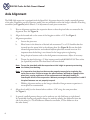
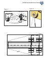
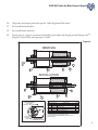
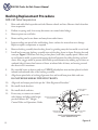
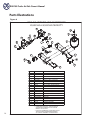
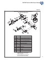
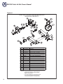
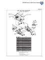
RAR-260
Trailer Air-Ride Suspensions
Owner’s Manual
www.ridewellcorp.com
P.O. Box 4586 l Springfield, MO 65808 l 417.833.4565 l 417.833.4560 (fax)
0814
Suspension Identification:
Ridewell Suspensions are identified by a metal tag attached to the left-hand hanger that indicates part
number, revision level, and serial number.
Parts:
For optimum suspension performance, order only Ridewell parts. Replacement parts for Model RAR-260
are shown on pages 14-17 of this manual.
Sales, Service & Warranty:
If you need assistance regarding this product, please contact us and we will be glad to help you.
Mailing Address
Shipping Address
Phones, Fax, E-mail
Ridewell Corporation
P.O. Box 4586
Springfield, MO 65808
Ridewell Corporation
3715 East Farm Rd. 94
Springfield, MO 65803
800.641.4122, 417.833.4565
417.833.4560 (fax)
[email protected]
RAR-260 Trailer Air-Ride Owner’s Manual
Contents
Pre-Installation Notes.........................................................................................................3
Configuration....................................................................................................................................4
Installation - General............................................................................................................................4
Installation - Axle to Suspension...........................................................................................5
Installation - Suspension to Frame..............................................................................................5
Axle Alignment................................................................................................................6-7
Torque Requirements...........................................................................................................8
Height Control System Installation.....................................................................................9
Bushing Check Procedure....................................................................................................9
Bushing Replacement Procedure...................................................................................10-12
Weld Process.....................................................................................................................13
Parts Illustrations.........................................................................................................14-17
Maintenance Schedule.......................................................................................................18
Warranty......................................................................................................................................18
Pre-Installation Notes
1. Suspensions are designed to operate within specific parameters. Operating the suspension
outside the design parameters may result in improper performance, damaged equipment
and voiding of the warranty.
2.
The total operating capacity of a suspension / running gear system is determined by the
component with the lowest load rating. Please consult with the manufacturers of axles,
brakes, tires and wheels to determine the maximum suspension system capacity.
3.
The installer is responsible for ensuring that air volume requirements are met. Consult
Federal Motor Vehicle Safety Standards (FMVSS) 121 for more information.
4.
Welding or altering suspension components is not permitted except where explicitly
stated by Ridewell Corporation.
3
RAR-260 Trailer Air-Ride Owner’s Manual
CHART 1
TIRE LOADED RADIUS
Configuration
The Ridewell model RAR-260 suspension is designed to accommodate a
range of ride heights for each specific model and can be used on a variety
of axle types for various applications. The following characteristics are
commonly referenced for set-up of the suspension:
1. Ride Height (also called Mounting Height) - The distance
from the bottom of the trailer frame to the centerline of
the axle. Ride height is related to frame height (the
distance from the bottom of the frame to the ground) by
the following formula:
Ride Height = Frame Height - Loaded Tire Radius
The loaded tire radius for common tire sizes can be found in Chart 1.
2.
Tubeless
Metric
215/75R17.5
Static
Loaded
Radius
14
8.5R17.5
235/75R17.5
14.5
9R17.5
225/70R19.5
15
10R17.5
245/70R19.5
15.5
265/70R19.5
285/70R19.5
16
16
305/70R19.5
16.5
255/70R22.5
245/75R22.5
235/80R22.5
17
17
17
275/70R22.5
17.5
265/75R22.5
255/80R22.5
18
18
305/70R22.5
18.5
8R22.5
9R22.5
Beam Centers - The centerline-to-centerline distance from
10R22.5 295/75R22.5
19
275/80R22.5
19
one trailing arm beam to the other. For the RAR-260, this
11R22.5 295/80R22.5
19.5
is also the same as the centerline-to-centerline distance
315/80R22.5
19.5
from one hanger to the other. The RAR-260 is designed to
285/75R24.5
19.5
275/80R24.5
19.5
fit up onto standard I-beam trailer frames at beam centers
385/65R22.5
19.5
that correspond to standard axle track widths as shown below
with standard wheel-end equipment. Installation at wider beam centers will reduce
suspension clearances; installation at narrower beam centers will de-rate the axle beam
capacity per the axle manufacturer’s specifications. For non-standard beam centers,
frames, frame centers, axle track or wheel-end equipment, the installer is responsible for
verifying clearances, axle capacity, proper fit-up, and any additional required support structure.
Standard Trailer Dimensions
Trailer Width
96”
102”
Axle Track
71.5”
77.5”
Frame Centers
38”
44”
Beam Centers
35”
41”
Air Spring Centers
31”
37”
Installation - General
4
1.
See the applicable RAR-260 engineering drawing for all dimensional requirements, part numbers, assembly details, torque values, etc. referred to in the installation procedures.
2. The exact sequence of installation and assembly of the suspension, installation of the height
control system, and completion of the axle alignment procedure is at the discretion of the
trailer manufacturer.
RAR-260 Trailer Air-Ride Owner’s Manual
Installation - Axle to Suspension
1.
A fixture to support the axle and suspension during the welding process is recommended.
Contact Ridewell engineering for applicable weld fixture number.
2.
Verify the beam centers and center the axle in the axle seats.
3.
For drum brake axles, space the cam off the tail of the beam per the drawing and ensure
that the brake chamber brackets are oriented properly. For disc brake axles, ensure that the
caliper assemblies are oriented properly and are rotated to proper position.
4.
Check the gap between the axle and the bottom of the axle seat at each end of each seat.
No gap greater than 1/16” allowed before clamping. After clamping the axle into the axle
seats, no gap is allowed.
5.
Weld the axle to the suspension trailing arms per Ridewell Weld Process #1 (see page 13).
Installation - Suspension to Frame
Note: The procedure in this section is recommended by Ridewell. Minor deviations from these guidelines
are permitted, especially in the details of welding the suspension to the trailer. The installer has ultimate
responsibility for attachment of the suspension to the trailer.
1.
Locate and mark the proper location of the suspension hangers and air spring plates on the
trailer frame. The frame must be clear in this area for proper suspension fit-up.
3.
Fabricate filler plates approximately as shown on the drawing and weld to the crossmembers
with ¼” fillet welds (it is recommended to place welds down the length of the crossmember,
not across it) and butt weld to frames. At the hanger, a single large filler plate in place of the
two small ones may be preferable.
2.
4.
5.
6.
7.
8.
Frame cross members should be located as shown on the drawing.
Locate and weld the hangers to the frame and filler plates with ¼” fillet welds. Stop welds
approximately ½” from corners and edges. A 1.5” diameter piece of pipe may be placed
through the holes in the hangers during this step as a stabilizer and aligning aide. For
hangers with wing gussets, the wing gussets must be welded to a crossmember or other
supporting structure.
Weld the air spring support plate to the frame and filler plate in similar fashion with 3/16”
fillet welds.
Locate a crossmember or diagonal brace to the front of the hangers as shown on the drawing
and attach with ¼” fillet welds.
All welds to be 70 ksi min. tensile strength. GMAW or FCAW recommended.
Assemble air springs and shock absorbers per the drawing. Ensure that no paint overspray gets
under the dust cover of the shock absorbers. Overspray that gets on the piston rod of a shock
will damage the seal and quickly cause the shock to leak during service.
5
RAR-260 Trailer Air-Ride Owner’s Manual
Axle Alignment
The RAR-260 suspension is equipped with the Speed Set® alignment feature for simple, manual alignment
of the axles. Depending on the suspension model, slots are provided in either the hanger sidewalls or bushing
assemblies (see Figure 1a) which allow 0.5” of adjustment at each pivot connection.
1.
Prior to alignment, position the suspension beams so that the pivot bolts are centered in the
alignment slots. See Figure 1a.
Align the forward axle to the center of the kingpin to within ± 1/8”. See Figure 2.
2.
3.
Alignment procedure:
a.
Loosen the pivot nut.
b.
Move beam in the direction of desired axle movement. Use a 1/2’’ shank breaker bar
inserted into the square hole in the adjuster plate. See Figure 1b. Ensure that both
inboard alignment washer and outboard adjuster plate have moved in unison. It is
important that the bushing is not skewed in the hanger prior to tightening.
c.
Snug the pivot fasteners and re-check alignment measurements. Adjust if necessary.
d.
Torque the pivot bolt using a 1” drive impact wrench and #6100054 E-20 Torx socket
(or equivalent) until the Torx head shears off from the bolt.
Note: Torque the pivot bolt with the suspension at ride height to prevent pre-stressing
the rubber pivot bushing.
Note: It is imperative that the pivot fasteners be properly torqued prior to placing the
trailer into service. Failure to torque the pivot fasteners will lead to slippage of the
pivot joint, causing rapid wear of the components and ultimately leading to
catastrophic failure of the suspension. Warranty coverage of the suspension is void if
the pivot fasteners are not properly torqued.
e. Welding alignment washers to the hanger sidewalls of hanger mount suspensions is
not required or recommended.
4.
Align the aft axle(s) to the forward axle to within ± 1/16” using the same procedure.
See Figure 2.
5. 6
In general, small alignment changes can be made on one side (left beam or right beam).
It is preferable that large alignment changes be made by splitting the difference from one
side to the other (i.e. 1/2 the difference forward at one beam, 1/2 the difference aft at
the other beam).
RAR-260 Trailer Air-Ride Owner’s Manual
Figure 1b
Figure 1a
YOKE MOUNT
HANGER MOUNT
PIVOT BOLT
ALIGNMENT
WASHER
ALIGNMENT
SLOT
PIVOT BOLT INITIALLY CENTERED
IN ALIGNMENT SLOT
Figure 2
7
RAR-260 Trailer Air-Ride Owner’s Manual
Torque Requirements
Design torque on all suspension fasteners
must be SET AND MAINTAINED BY INSTALLER.
Figure 3
25 - 30
Torque pivot bolt using a 1” drive impact wrench and #6100054 E-20 Torx socket (or equivalent)
until the Torx head shears off from the bolt.
Suspension fasteners to be retorqued initially at 6,000 miles (10,000 KM) and 50,000 miles
(80,000 KM) increments thereafter. Do not retorque pi vot fasteners.
This torque label, included in the carton of parts,
should be adhered to the chassis above the suspension.
25 - 30
Pivot Bolt/Nut
Shock Bolt/Nut
7/8” - 9NC
SEE BELOW
3/4” - 10NC 200 - 230 ft-lb
SEE BELOW
271 - 312 N·m
Air Spring Nut, Upper
3/4” - 16NF
45 - 50 ft-lb
61 - 68 N·m
Air Spring Nut, Lower
1/2” - 13NC
45 - 50 ft-lb
61 - 68 N·m
Air Spring Bolt, Lower
1/2” - 13NC
25 - 30 ft-lb
34 - 41 N·m
Torque pivot bolt using a 1” drive impact wrench and #6100054 E-20 Torx socket (or equivalent) until
the Torx head shears off from the bolt.
Suspension fasteners to be retorqued initially at 6,000 miles (10,000 KM) and 50,000 miles (80,000 KM)
increments thereafter. Do not retorque pivot fasteners.
See service manual for details or call (800) 641-4122
Ridewell Corporation, Springfield, MO USA www.ridewellcorp.com
8
Torque pivot bolt using a 1” drive impact wrench and #6100054 E-20 Torx socket (or equivalent)
until the Torx head shears off from the bolt.
Suspension fasteners to be retorqued initially at 6,000 miles (10,000 KM) and 50,000 miles
(80,000 KM) increments thereafter. Do not retorque pivot fasteners.
RAR-260 Trailer Air-Ride Owner’s Manual
Height Control System Installation
Install the appropriate height control valve, linkages, etc. per the Extreme AirTM Height Control Valve
Installation and Operations Guide for model RAR-260.
Bushing Check Procedure
The bushings in the RAR-260 suspension should be checked during any scheduled maintenance or
any time there is a suspected problem. Bushing problems can arise from breakdown of the natural
rubber over time or, in a severe application, by failure of the bond between the rubber and the metal
inner sleeve. The bushings should be checked if any of the following conditions are observed:
1.
Uneven tire wear.
2.
Abnormal forward-aft or lateral movement of the axle during operation.
3.
Rapid degradation of wear washers.
4.
Abnormal noises coming from the suspension.
To check, insert the flat end of a pry-bar between the sidewall of the hanger and the eye of the beam.
Applying moderate side load to the pry-bar, look for any relatively large or easy movement of the
beam in relation to the hanger. Note that a small amount of movement under load due to deflection
of the rubber is normal and acceptable. Repeat the process on the other side of the hanger. If large
or easy movement is noted, drop the beams down per the bushing replacement procedure for further
inspection of the bushing and replace if necessary.
9
RAR-260 Trailer Air-Ride Owner’s Manual
Bushing Replacement Procedure
RAR-260 Underslung or Overslung Suspension
Order RAR-260 bushing replacement kit number 6040098. The following describes bushing
removal and installation using tool number 6100051.
1.
Raise and safely block up trailer and axle. Remove wheels and tires. Remove shock absorbers
from suspension.
2.
Deflate air springs and, if necessary, disconnect air control valve linkage.
3.
Remove pivot nuts and bolts.
4.
Rotate trailing arm beams down and out of hangers.
5.
Inspect pivot holes and hanger surfaces for unusual wear or damage. Repair or replace
components as required.
6.
Using the locator mark on the bushing as reference, draw a line on the beam. See “Bushing
Orientation” portion of Figure 4. This will be used to orient the new bushing when installed.
7.
Lubricate the threads and bearings of the bushing installation tool with grease.
8.
Assemble the bushing installation tool to the bushing and beams as shown in the “Removal”
portion of Figure 4 and ensure that the tool is squarely seated on the beam eye. Rotate the
hex nut of the threaded rod with an impact wrench to press out the old bushing. A small
amount of heat should be applied to the beam eye to break the bushing loose. Use of a ¾”
drive impact is recommended.
9.
Disassemble the bushing installation tool.
10.
Clean the bushing eye of corrosion and debris.
11. Apply Seagull Type “M” lubricant to the new bushing outer diameter, inside the beam eye
and inside the cone. This lubricant is included in the bushing replacement kit; do not
substitute.
12. Reassemble the bushing installation tool as shown in the “Installation” portion of Figure 4
and ensure that the tool is squarely seated on the beam eye. Align the locator mark on the new bushing with the reference line drawn on the beam. Install the new bushing by rotating
the hex nut of the threaded rod with an impact wrench; prevent the plunger assembly from
rotating by holding its hex nut with an open end wrench.
13.
Remove the bushing installation tool and ensure that the bushing is centered in the beam eye.
14. Re-assemble beams to hangers with new UHMW polyethylene wear washers and pivot
sizing washers.
10
15.
Align bushing sleeves to hanger alignment slots and install new pivot bolts, washers and nuts.
DO NOT REUSE SHEAR-TYPE PIVOT BOLTS.
RAR-260 Trailer Air-Ride Owner’s Manual
16.
Align axle and torque pivot bolts per the “Axle Alignment Procedure.”
17.
Re-install shock absorbers.
18.
Re-install wheels and tires.
19.
If necessary, re-connect air control valve linkage and adjust ride height per the Extreme AirTM
Height Control Valve and Operations Guide.
Figure 4
REMOVAL
5
4
3
2
1
6
INSTALLATION
5
4
6
3
2
1
DRAW REFERENCE
LINE USING
BUSHING LOCATOR MARK
BUSHING
LOCATOR
MARK
6100051 BUSHING INSTALLTION TOOL PARTS LIST
ITEM
1
PART NO.
DESCRIPTION
-------BEAM BUSHING EYE
QTY
-
2
1110084
BUSH CAVITY TENNECO MB96B914260
-
3
5340038
END CAP ASSY.
1
4
5340039
PLUNGER ASSEMBLY
1
5
5360003
NUT,ALLTHREAD ASSY
1
6
6100053
CONE, TOOL
1
* ITEM SHOWN FOR REFERENCE ONLY
NOT INCLUDED WITH BUSHING INSTALLATION
TOOL 6100051
BUSHING
ORIENTATION
11
RAR-260 Trailer Air-Ride Owner’s Manual
Bushing Replacement Procedure
RAR-260 Yoke Suspension
1. Raise and safely block up trailer and axle. Remove wheels and tires. Remove shock absorbers from suspension.
2. Deflate air springs and, if necessary, disconnect air control valve linkage.
3. Remove pivot nuts and bolts.
4. Rotate trailing arm beams down and away from trailer frames.
5. Inspect trailing arm pivot holes and bushing sleeve surfaces for unusual wear or damage. Repair or replace components as required.
6. Remove bushing assembly from bushing sleeve by grinding away the four welds on each end.
7. Install and center new bushing assembly into each bushing sleeve in frame. Position slot and
seam per Figure 5. Weld one inch long at four places, both sides, equally spaced. Allow steel
to cool between welds, to prevent damaging the bond between the rubber bushing and steel
sleeve. Also, stagger welds to prevent heat build-up and distortion by welding top of sleeve at
outboard side of frame, then bottom of sleeve at inboard side of frame, and moving around
the sleeve in 90º increments.
8. Re-assemble beams to frames with new UHMW polyethylene wear washers placed on both
inboard and outboard sides of the bushing assembly.
9. Align beam pivot holes to bushing alignment slots and install new pivot bolts and nuts.
DO NOT REUSE SHEAR-TYPE PIVOT BOLTS.
10. Align axle and torque pivot bolts per the “Axle Alignment Procedure.”
11. Re-install shock absorbers.
12. Re-install wheels and tires.
13. If necessary, re-connect air control
valve linkage and adjust ride height
per the Extreme AirTM Height
Control Valve and Operations Guide.
BUSHING SLEEVE
IN FRAME
BUSHING ASSY
POSITION SLOT IN BUSHING
ASSY HORIZONTAL
(45°)
SEAM IN BUSHING
SLEEVE (REF)
45°
SEAM IN BUSHING
ASSY
YOKE SUSPENSION BUSHING
ASSY ORIENTATION
Figure 5
12
RAR-260 Trailer Air-Ride Owner’s Manual
Weld Process #1
ROOT
PASS
0.50
SECOND
PASS
.38
THIRD
PASS
.125 MAX
AXLE
AXLE
AXLE
BEAM AXLE SEAT
BEAM AXLE SEAT
WELD JOINT PREPARATION
AXLE
0.50
BEAM AXLE SEAT
BEAM AXLE SEAT
FIRST PASS
THIRD PASS
SECOND PASS
ARC START
ARC START
ARC STOP
3.0
ARC STOP
THIRD PASS
THIRD PASS
NO WELD
TOP OF AXLE
SECOND PASS
SECOND PASS
FIRST PASS
FIRST PASS
4.0
1.0 TYP
1.0 TYP
NO WELD
BOTTOM
OF AXLE
NO WELDING ZONE
SMAW
GMAW / FCAW
REPRESENTATIVE AXLE SEAT (PROFILE DEPENDENT ON SUSPENSION PRODUCT)
1 - WELD JOINT PREPARATION: ALL GREASE, DIRT, PAINT, SLAG OR OTHER CONTAMINANTS MUST BE REMOVED FROM THE WELD JOINT
WITHOUT GOUGING THE AXLE TUBE. INSURE THE LOWER BEAM ASSEMBLY FITS THE AXLE WITH A ROOT GAP OF 0.125 INCH
MAXIMUM BETWEEN THE AXLE AND THE BEAM AXLE SEAT AS ILLUSTRATED ABOVE. IT IS RECOMMENDED TO C-CLAMP THE AXLE TO AXLE
BEAM SEAT PRIOR TO WELDING TO INSURE THAT PROPER CONTACT OCCURS BETWEEN THE AXLE AND THE BEAM SEAT. SEE ILLUSTRATION
BELOW.
2 - WELDING PRECAUTIONS: ALL WELDS MUST BE KEPT AWAY FROM THE TOP AND BOTTOM OF THE AXLE WHERE MAXIMUM STRESSES
OCCUR. THE "NO WELD" ZONES ARE ILLUSTRATED ABOVE. DO NOT TEST WELD THE ARC ON ANY PART OF THE AXLE TUBE. THIS CAN LEAD
TO A SMALL CRACK THAT MAY EVENTUALLY GROW AND AFFECT THE FATIGUE LIFE OF THE AXLE.
3 - ALL WELDERS AND WELDING OPERATORS SHOULD BE CERTIFIED PER AMERICAN WELDING SOCIETY (AWS) D1.1 SECTION 5 PROCEDURES
OR EQUAL.
4 - RECOMMENDED WELDING METHODS ARE SHIELDED METAL ARC (SMAW (STICK)), GAS METAL ARC (GMAW (SOLID WIRE)), OR FLUX CORED
ARC (FCAW (FLUX WIRE)) WELDING. WHATEVER ELECTRODE AND METHOD USED MUST DEVELOP A MINIMIMUM WELD TENSILE STRENGTH
OF 70,000 P.S.I. REFER TO THE ELECTRODE MANUFACTURER'S RECOMMENDATION FOR VOLTAGE, CURRENT AND SHIELDING MEDIUM FOR
THE DIAMETER ELECTRODE TO BE USED SO THE BEST FUSION AND MECHANICAL PROPERTIES CAN BE OBTAINED. RECOMMENDED
ELECTRODE IS E7018 IF SMAW IS USED. RECOMMENDED ELECTRODE IS E70S-1 OR E70T-1 IF GMAW OR FCAW WELDING IS USED.
5 - ALL ELECTRODES USED SHOULD MEET AWS SECTION 5 SPECIFICATIONS AND CLASSIFICATIONS FOR WELDING CARBON AND LOW ALLOY
STEELS.
6 - IF SMAW ELECTRODES (STICK) ARE USED, THEY MUST BE NEW, DRY, FREE OF CONTAMINANTS AND COME FROM A STOCK THAT HAS BEEN
PURCHASED AND STORED PER AWS SECTION 4.5.2, LOW HYDROGEN ELECTRODE STORAGE SPECIFICATIONS.
7 - GROUND THE AXLE TO ONE OF THE ATTACHED AXLE PARTS SUCH AS THE AIR CHAMBER BRACKETS, CAM BRACKETS OR BRAKE SPIDER.
NEVER GROUND THE AXLE TO A WHEEL OR HUB AS THE SPINDLE BEARING MAY SUSTAIN DAMAGE.
8 - THE AXLE ASSEMBLY SHOULD BE AT A MINIMUM TEMPERATURE OF 60 DEGREES F (15 DEGREES C) PRIOR TO WELDING. PRE-HEATING THE
WELD ZONE TO THE AXLE MANUFACTURER'S PRE-HEAT TEMPERATURE IS RECOMMENDED. THIS WILL MINIMIZE THE FORMATION OF
MARTENSITIC OR BRITTLE METAL STRUCTURES IN THE FUSION LINE OR THE HEAT AFFECTED ZONE WHICH MAY CONTRIBUTE TO A
PREMATURE FATIGUE FAILURE IN SERVICE.
9 - THE JOINT TO BE WELDED SHOULD BE POSITIONED IN THE FLAT OR HORIZONTAL POSITION.
10 - MULTIPLE PASS WELDING SHOULD BE USED ON THE BEAM/AXLE CONNECTION USING THE FOLLOWING GUIDELINES. TOTAL FILLET WELD
SIZE SHOULD BE 0.5 INCH.
11 - MULTIPLE PASS WELD INITIATION AND TERMINATION SHOULD BE PERFORMED AS SHOWN ABOVE. ALL SLAG MUST BE REMOVED BETWEEN
PASSES. BACKSTEP FILL ALL CRATERS. EACH PASS MUST BE ACCOMPLISHED IN ONE OR TWO SEGMENTS. NEVER START OR STOP WELDS
AT THE END OF THE WELD JOINT. START WELDS AT LEAST 1" FROM END AND BACKWELD OVER THE START. WELDS MUST GO TO WITHIN
1/8" +/- 1/16" OF THE ENDS OF THE AXLE SEAT AND MUST NOT GO BEYOND OR AROUND THE ENDS.
12 - POST-WELD PEENING (RECOMMENDED, BUT NOT REQUIRED): NEEDLE PEEN THE ENTIRE TOE OF THE SECOND PASS, INCLUDING AROUND
THE ENDS OF THE AXLE SEAT. HOLD THE NEEDLES PERPENDICULAR TO THE AXLE. A UNIFORM DIMPLED PATTERN WILL APPEAR WHEN
PROPERLY PEENED.
C
10102
REVISED WELD DIMENSIONS.
6/25/10
B
10102
REVISED NOTES 11 AND 12.
2/3/10
G.H. MDJ CJB
A
07100
ADDED 215 TO LIST OF SUSPENSION MODELS COVERED
2/26/07
G.H. MDJ DK
REV PROJECT
.125 MAX
CBC
CHECKED:
MDJ
2/21/2003
CJB
2/21/2003
6/23/2010
PROJECT NO:
SCALE:
A-SIZE:
03103
MATERIAL:
CORRECT
INCORRECT
CHK APPD
PO BOX 4586 SPRINGFIELD, MISSOURI 65808
TITLE:
NTS
RIDEWELL WELD PROCESS #1,
5" DIA. AXLE, 3 PASS WELD
WEIGHT:
-
BY
RIDEWELL CORPORATION
R
APPROVED:
DATE
DESCRIPTION
DRAWN BY:
G.H. MDJ CJB
-
REV:
PART NO:
APPLICABLE SUSPENSION MODELS: 200, 225, 240, 245R, 215, 243, 260.
SHEET
1
OF
1
WELD PROCESS #1
C
13
RAR-260 Trailer Air-Ride Owner’s Manual
Parts Illustrations
Figure 6
RAR-260 UNDERSLUNG SUSPENSION
25,000 LB & 30,000 LB CAPACITY
14
9
7
12
14
16
3
18
13
1
19
7
6
8
4
10
15
2
11
10
5
15
ITEM
*
*
*
*
*
*
PART NO.
DESCRIPTION
1
SEE DRAWING
AIR SPRING
2
1110084
BUSH CAVITY TENNECO MB96B914260
3
1130031
PIVOT BOLT, SHEAR-TYPE 7/8" 9NC 10"LG
4
1140022
HHCS 3/4" 10NC 11"LG GR 8
5
1145383B105
HHCS 1/2" 13NC 1-1/4"LG GR 5
6
1147698B105
HHCS 3/4" 10NC 3-1/4"LG GR 5
7
1150023
L'NUT 3/4"-10NC CENTER LOCK GR-B
8
1150032
L'NUT 7/8" 9NC GR8 SECURELOK
9
1150558B102
NUT 3/4" 16NF GRD 2
10
1160021
WEAR WASHER UHMW-PE
11
1160556B100
L'WASHER 1/2" S/T MED
12
1160868B100
WASHER 7/8" A-325 FLAT
13
1270563B003
SHOCK ASSY 6" MONROE
14
SEE DRAWING
HANGER ASSY
15
SEE DRAWING
BEAM ASSY
16
A/SPG PLATE
17
SEE DRAWING
-
18
7002249
ALIGNMENT WASHER
19
7002686
ADJUSTER PLATE 4.0"OD
NOT USED
NOTES:
1 - ITEMS INDICATED WITH * ARE INCLUDED IN
BUSHING REPLACEMENT KIT NO. 6040098.
ORDER 1 KIT PER AXLE.
14
2 - FOR PART NUMBERS NOT SPECIFIED PLEASE
SEE APPLICABLE ENGINEERING DRAWING
OR CONTACT RIDEWELL FOR ASSISTANCE.
RAR-260 Trailer Air-Ride Owner’s Manual
Figure 7
RAR-260 OVERSLUNG SUSPENSION
25,000 LB CAPACITY
8
13
11
8
6
3
15
12
10
17
1
13
4
6
18
4
7
9
2
14
5
9
14
ITEM
*
*
*
*
*
*
PART NO.
DESCRIPTION
1
SEE DRAWING AIR SPRING
2
1110084
BUSH CAVITY TENNECO MB96B914260
3
1130031
PIVOT BOLT,SHEAR-TYPE 7/8" 9NC 10"LG
4
1147698B105
HHCS 3/4" 10NC 3-1/4"LG GR 5
5
1150012
L'NUT 1/2" 13NC FLANGED T-L GR 8
6
1150023
L'NUT 3/4"-10NC CENTER LOCK GR-B
7
1150032
L'NUT 7/8" 9NC GR8 SECURELOK
8
1150558B102
NUT 3/4" 16NF GRD 2
9
1160021
WEAR WASHER UHMW-PE
10
1160868B100
WASHER 7/8" A-325 FLAT
11
1230059
PIPE PLUG, 1/4" MNPT, HEX SOCKET
12
1270563B003
SHOCK ASSY 6" MONROE
13
SEE DRAWING HANGER ASSY
14
SEE DRAWING BEAM ASSY
15
7000894
-
AIR SPRING MOUNTING PLATE
16
17
7002249
ALIGNMENT WASHER
18
7002686
ADJUSTER PLATE 4.0"OD
NOT USED
NOTES:
1 - ITEMS INDICATED WITH * ARE INCLUDED IN
BUSHING REPLACEMENT KIT NO. 6040098.
ORDER 1 KIT PER AXLE.
2 - FOR PART NUMBERS NOT SPECIFIED PLEASE
SEE APPLICABLE ENGINEERING DRAWING
OR CONTACT RIDEWELL FOR ASSISTANCE.
15
RAR-260 Trailer Air-Ride Owner’s Manual
Figure 8
RAR-260 OVERSLUNG SUSPENSION
30,000 LB CAPACITY
13
8
8
15
6
3
17
11
1
12
13
5
18
6
5
7
9
14
10
2
4
9
14
*
*
*
*
*
*
ITEM
PART NO.
1
SEE DRAWING
AIR SPRING
DESCRIPTION
2
1110084
BUSH CAVITY TENNECO MB96B914260
3
1130031
PIVOT BOLT, SHEAR-TYPE 7/8" 9NC 10"LG
4
1145383B105
HHCS 1/2" 13NC 1-1/4"LG GR 5
5
1147698B105
HHCS 3/4" 10NC 3-1/4"LG GR 5
6
1150023
L'NUT 3/4"-10NC CENTER LOCK GR-B
7
1150032
L'NUT 7/8" 9NC GR8 SECURELOK
8
1150558B102
NUT 3/4" 16NF GRD 2
9
1160021
WEAR WASHER UHMW-PE
10
1160556B100
L'WASHER 1/2" S/T MED
11
1160868B100
WASHER 7/8" A-325 FLAT
12
1270563B003
SHOCK ASSY 6" MONROE
13
SEE DRAWING
HANGER ASSY
14
SEE DRAWING
BEAM ASSY
15
AIR SPRING PLATE 10" OCT 7.75"
16
7000004
-
17
7002249
ALIGNMENT WASHER
18
7002686
ADJUSTER PLATE 4.0"OD
NOT USED
NOTES:
1 - ITEMS INDICATED WITH * ARE INCLUDED IN
BUSHING REPLACEMENT KIT NO. 6040098.
ORDER 1 KIT PER AXLE.
2 - FOR PART NUMBERS NOT SPECIFIED PLEASE
SEE APPLICABLE ENGINEERING DRAWING
OR CONTACT RIDEWELL FOR ASSISTANCE.
16
RAR-260 Trailer Air-Ride Owner’s Manual
Figure 9
RAR- 260 YOKE SUSPENSION
25,000 LB CAPACITY
17
BUSHING SLEEVE
WELDED INTO
TRAILER F RAME
TRAILER F RAME
& CROSSMEMBERS
18
PIVOT BUSHING ASSY
INSTALLED IN
15
SLEEVE
5
8
6
12
16
3
6
1
11
15
10
2
7
14
9
13
4
ITEM
1
*
*
*
*
*
PART NO .
DESCRIPTION
SEE DRAWING
AIR SPRING
2
1130031
PIVOT BOLT , SHEAR-TYPE
3
1140022
HHCS 3/4" 10 NC 11" LG GR 8
4
1145383 B 105
HHCS 1/2" 13 NC 1-1/4"LG GR 5
5
1147698 B 105
HHCS 3/4" 10 NC 3-1/4"LG GR 5
6
1150023
L'NUT 3/4"-10NC CENTER LOCK GR-B
7
1150032
L'NUT 7/8" 9NC GR 8 SECURELOK
8
1150558 B 102
NUT 3/4" 16 NF GRD 2
9
1160556 B 100
L'WASHER
10
1160868 B 100
WASHER
1/2" S /T MED
7/8" A-325 F LAT
11
1167680 B 000
WEAR WASHER UHMW-PE
12
1270563 B 003
SHOCK ASSY
13
4280266
BEAM ASSEMBLY
, LH
14
4280267
BEAM ASSEMBLY
, RH
15
5450021
BUSHING ASSY BONDED YOKE
16
7001723 B 000
AIR SPRING PLATE
17
8147716 B 000
SHOCK MOUNT
18
8990027
SLEEVE BUSH OUTER YOKE
NOTES:
7/8" 9NC 10" LG
6" MONROE
260
260
1 - ITEMS INDICATED WITH * ARE INCLUDED IN
BUSHING REPLACEMENT KIT NO
. 6040099.
ORDER 1 KIT PER AXLE .
2 - F OR PART NUMBERS NOT SPECI
F IED PLEASE
SEE APPLICABLE ENGINEERING DRAWING
OR CONTACT RIDEWELL
F OR ASSISTANCE .
17
RAR-260 Trailer Air-Ride Owner’s Manual
Maintenance Schedule
To keep your Ridewell suspension in optimum working order, we recommend following maintenance.
Every 1,000
miles
Bushings
Air Springs
Structure
Ride Height
Fastener Torque
First 6,000 miles
of operation
Every 12,000
miles
Every 50,000
miles
I
I
I
I
T
T
I - Inspect, L = Lubricate, T = Tighten, R = Replace
Warranty
This warranty applies for usage within the USA. For usage outside the USA, please contact Ridewell.
The Ridewell Corporation warrants the suspension systems manufactured by it to be free from defects
in material and workmanship, under proper use, installation, application, and maintenance on highway
trailers for a period of 5 years with no mileage limit, after delivery to the original purchaser. The
responsibility of the Ridewell Corporation under this non-transferable warranty is limited to making
good at the company factory by repair or replacement of any part or parts which it manufactures.
Written permission for any claim return must be first obtained from authorized Ridewell personnel. All
returns must have transportation charges prepaid by the customer and accompanied with a complete
written explanation of claimed defects and the circumstances of operational failure. On all component
parts not manufactured by Ridewell their warranty is to the extent that the manufacturer of such parts
warrant them to Ridewell Corporation. This is the only authorized Ridewell warranty and is in lieu
of all other expressed or implied warranties or representations, including any implied warranties of
merchantability or fitness, or of any obligations on the part of Ridewell Corporation. In no event will
Ridewell be liable for business interruptions, loss of profits, personal injury, cost of delay, or for any
other special, indirect, incidental or consequential losses, costs or damages.
Subject to all of the above conditions, if repair or replacement of any defective part is made by
Ridewell Corporation, Ridewell will return the repaired or replaced part to the original purchaser with
transportation charges prepaid.
Years 1-3
Years 4-5
18
100% Parts & labor
100% Parts (pivot bushing excluded)


![Trailer Roll Stability (TRS) Installation Manual [L30040]](http://vs1.manualzilla.com/store/data/006020641_1-040a22153212ab13bbec744ca183c148-150x150.png)