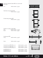
1
EN
Manual for assembly and use Modular Triangular Bridge (MTB)
MTB with Roof Edge Protection Manual (DRB)
DE
Aufbau- und verwendungsanleitung Modulare Dreiecksbühne (MTB)
und MTB mit Dachrandsicherung (DRB)
EN 12811
750147-B-1011
EN 13374
www.altrex.com
Relax. It ’s an Altrex.
EN
Manual for assembly and
use Modular Triangular Bridge (MTB)
and MTB with Roof Edge Protection (DRB)
Art. No. 750147-B-1011
Version 10/2011
Copyright Altrex B.V. © ’11
All rights reserved. No part of this
publication may be duplicated, stored in
an automated data file, or disclosed in
any way or form, whether electronically,
mechanically by photocopying, recording,
or in any other way, without prior consent
from Altrex B.V. Zwolle. This publication
may only be used for Altrex products.
Misprints and printing errors reserved.
Relax. It ’s an Altrex.
pag.
2 of 44
General
Before use, always read the manufacturer’s (Altrex BV) user manual properly and thoroughly.
The load capacity is classified in accordance with class 2 of NEN 12811. The permitted floor
load of the MTB upright 3-5 m (331535) is 150 kg/m2, up to a maximum of 500 kg distributed
evenly across the floor. For the MTB upright 4-6 m (331536), the permitted floor load is 150
kg/m2 with a maximum of 350 kg distributed evenly across the floor.
Do not use the MTB with parts produced by other manufacturers. Only use the MTB with the
parts stipulated in this user manual.
The assembly and use of the MTB is only permitted at a wind force not exceeding 6 Beaufort
(< 14m/s).
When used in conjunction with leg posts, the MTB can be used at a minimum platform height
of 3 m and a maximum platform height of 5 m or a minimum floor height of 4 m and a maximum floor height of 6 m.
Always position the leg post at the correct angle against the wall (approx. 70°). All three feet
of the leg post will then be in contact with the ground.
Always position the leg post of the MTB on a solid, stable, horizontal and non-slippery surface, with adequate bearing capacity. If the foundation is soft and/or sloping, place a plank
and/or ground peg below and/or behind the base of the MTB upright, to prevent it from sliding
away. Do not support against a weak wall, such as a synthetic curtain wall.
After setting the height of the MTB, always use the securing pin to secure the correct operating height. Allow the work platform to rest on the securing pin. Only then can the work
platform support a load.
NB: Walking on the work platform before this lock has been fixed in place is not permitted!
Always use a ladder to gain access to a secured work platform.
When using the weather protection (the Altrex Shelter System) or roof edge protection (Roof
Edge Protection - DRB) the leg posts of the MTB and the leg posts of the Shelter System have
to be anchored to the wall.
Should you wish to use the MTB for reasons other than those mentioned above, you should
contact the manufacturer.
The MTB system should never be used as a goods and/or passenger lift.
When assembling, the following points should be checked:
•
The load-bearing capacity of the ground surface must be adequate
•
Any obstructions around the workplace to the assembly and use of the MTB.
•
The wind force.
•
The winch cable of the leg posts must be undamaged and neatly rolled
•
The availability of all required parts at the workplace.
•
Damaged or incorrect parts must not be used.
At least two people should assemble the MTB.
Relax. It ’s an Altrex.
pag.
3 of 44
EN
EN
These persons should be appropriately qualified.
Only assemble the MTB after these instructions have been read thoroughly.
When assembling the MTB, all the required parts have to be used and, after assembly, these
should be checked to make sure they are reliably fixed. Use of the operating bridge without
guide rails or platforms is not permitted.
Deviation from this user manual is not permitted.
Use
When the MTB is (re)used, the following points have to be checked:
•
is the structure still complete and in a good condition.
•
are all fasteners still in place.
•
does the site still allow safe operation.
•
are the winch and lifting cable in a good condition.
The MTB may only be accessed via a ladder on the side which is supported against the wall.
Materials and tools are to be transported to the working platform manually using (for
example) a rope and a bucket. These should be lifted as close to the scaffold as possible.
The use of hoisting devices to the MTB that are not manually powered is not permitted.
The MTB should be raised without a load.
Particular attention should be paid to the wind force when using the MTB in wind-susceptible
areas, for example open constructions and at the corner of a building. If required, extra fasteners should be used.
The MTB can be used as Roof Edge Protection including work platform, or on its own as Roof
Edge Protection! Check that the trolley has been reinforced for its intended use in Roof Edge
Protection. The trolley has a green sticker (see photo) and can be identified visually by the
reinforced connection point of the truss (see photo). Without this reinforced trolley, the MTB
upright cannot be used as Roof Edge Protection!
Relax. It ’s an Altrex.
pag.
4 of 44
Replacing the trolley
EN
NL
If the trolley has to be replaced, the following instruction applies:
1. Ensure there is some play in the cable.
2. Disassemble the eye of the cable on the trolley.
3. Remove the cable.
4. Take the upright apart.
5. Remove the “old” trolley and fit the reinforced trolley with green sticker.
6. Reassemble the upright.
As Roof Edge Protection, the MTB is can be added to. Between the two ends of the MTBs with
Roof Edge Protection guardrail brace uprights, the space must be no more than 10 cm.
If a person or object falls into the Roof Edge Protection system, the entire system can only be
used once an inspection has been performed by an authorised person; please contact Altrex
B.V. or your Altrex Dealer.
The Roof Edge Protection has to have a minimum of 2 metres overhang in respect of the workplace (e.g. dormer window)!
≥2m
Disassembly
Disassembly should be carried out in reverse order of the assembly of the MTB.
Inspection, Care and Maintenance
Parts must be handled and transported with care, in order to avoid damage.
Storage should be organised in such a way that only undamaged parts, in the correct
amounts, arrive at the location of assembly of the MTB.
Check all parts for correct functioning and to ensure these are not contaminated.
Check all parts for damage.
Damaged parts have to be returned to the manufacturer for repair, or they should be destroyed.
Relax. It ’s an Altrex.
pag.
5 of 44
EN
The moving parts of the winch have to be frequently lubricated with oil.
The MTB has to be inspected annually for any defects.
Altrex can carry out this inspection.
To transport the Roof Edge Protection, you can loosen the lowermost bolts of the guardrail
brace. Ensure there is play in the strapping strips and slide the top part upwards.
Hang the top part over the guardrail at the bottom and do not forget to fit the bolt/nut.
Storage of the safety nets
The safety nets are made from six ultra-strong polyamide fibres or ultra-strong reflective polypropylene and have excellent sun resistant and tear resistant properties.
Despite that, you should take the following precautions:
• Store the nets in dry rooms on wooden planks or in closed containers. If they become
damp, they have to be dried before being stored.
• The nets have to be protected from UV radiation.
• The nets must not be stored close to heat sources or where contact with hazardous materials or substances is possible (solvents, oil, welding particles, radiation, etc.).
• In the event of possible contact with welding particles, cover the nets with a fire-resistant
sleeve.
Inspection of the safety nets.
The safety nets have to be tested and inspected for:
• Ruptures in the wire ropes.
• Objects within the reach of the nets.
• Rust formation through metal objects.
• Damaged wires or fibres through friction, etc.
Replacement of safety nets.
The safety nets have to be replaced in the following cases:
- If someone falls into the net, it has to be replaced with a new net and sent to the factory for
inspection.
- If materials such as rubble, bricks or other small objects fall into the net, but the fibres or
the interweaving are still intact, remove the materials from the net.
- If heavy materials fall into the net, even if the fibres or the interweaving are still intact, we
advise that the net is replaced and sent to the factory for inspection. If the fibres or the
interweaving are broken, replace the net with a new one.
- Always replace the net four years after the date of purchase.
Relax. It ’s an Altrex.
pag.
6 of 44
Warranty conditions
EN
This Altrex product has been designed, manufactured and tested with the greatest care. Should
this product be used in accordance with the instructions and its intended use, a warranty will apply under the following conditions:
Altrex guarantees the reliability of the product and the quality of the materials used for the product.
We will rectify any defects that are covered by the warranty by replacing the defective part, or the
product itself, or by supplying a part for replacement.
Not covered by the warranty are any defects that occur as a result of the following:
a) Use of the product contrary to its intended use or contrary to the instructions for use.
b) Normal wear and tear of the product.
c) Assembly or repair by the client or by third parties (with the exception of fitting the spare parts
provided by Altrex as indicated above).
d) Any modified governmental regulations concerning the nature or quality of the material used in
the product.
Any defects that are found upon the delivery of the product should be reported immediately to
Altrex. Should notification of these defects not take place immediately, the warranty will be null
and void. To make a claim under the warranty, Altrex or your Altrex dealer has to be provided with
the proof of purchase.
Any defects of the product have to be reported to Altrex or your Altrex dealer as soon as possible,
but in any case within 14 days of the defect being found.
a) Should a claim be made under the warranty conditions, Altrex has to have the opportunity to be
able to investigate the product in its Quality Centre. The client must make the product available
for this purpose. Should it be established during the investigation that the product has been
used incorrectly, the costs of the investigation will be charged to the client.
b) Should the client ask for an investigation to be carried out by an independent institute, the
costs for this investigation are at the expense of the client should it be established during the
investigation that the product has been used incorrectly. The costs of the investigation are also
at the expense of the client if, prior to this investigation, Altrex offered to repair or to replace
the product at no charge to the client.
Relax. It ’s an Altrex.
pag.
7 of 44
EN
Winch/cable manual
General
Read, understand and follow all instructions regarding the use of the winch and the fitting of the
cable.
Do not permit anyone unfamiliar with these operating instructions to use the winch!
Avoid the presence of oil and grease on the brake discs as this can result in brake slippage,
which would allow the MTB to drop.
Meticulously follow the instructions in this manual and the stickers on the winch. Disregarding
these instructions can result in bodily injury, damage to property or even worse.
NEVER use this winch for lifting people.
Only use this winch to hoist the MTB, without any other load.
Before each use, check the cable and the cable connection for damage.
Never use a damaged and/or worn cable as shown in the table below.
Inspection criteria for the MTB cable
Action
Visible cut-through or worn-through strands
Replace the cable
§
Space between the cable and thimble > 4mm
Replace the cable
The cable must always be fully wound a minimum of three times around the drum.
A loud clicking sound of the ratchet mechanism must always be audible when hoisting the MTB.
If the loud clicking is not audible, do not use the winch, but firstly check the ratchet mechanism
parts and if necessary replace these.
Do not release the winch handle until the ratchet is secured in place and the MTB is thus being
supported.
Relax. It ’s an Altrex.
pag.
8 of 44
Never work with slippery, wet or greasy hands and always make sure you have a secure grip on
the handle of the winch.
Never allow the MTB to hang by the cable during use, but secure the trusses as outlined.
1
2
3
4
5
Replacing/fitting the cable to the winch drum:
6
7
8
9
Rotate the cable around the axle and insert the end between the cable and the winch. Check
thoroughly that the way in which the cable is fitted is exactly the same as shown on the drawing
(image 1).
Position the leg post horizontally, with the winch pointing upwards.
Detach the cable connection from the drum and wind the cable of the drum. Make a note of how
the cable was fixed to the winch.
Disconnect the cable from the trolley by loosening the D connection.
Using the D connection reattach the new cable to the trolley. Feed the cable over the pulley at the
top of the leg post (feed the cable through from the bottom to the top)
Feed the cable via the inside of the winch through the opening with the groove. The cable has to
be run through behind the winch axle
Make a knot in the end of the cable that has been fed through (image 2).
Secure the cable using the 2 bolts, 2 washers, 2 nuts and locking plate. Tighten this properly using
an open-end spanner, ring spanner or socket spanner (image 2).
Tightly wind the cable around the drum of the winch.
image 1
Relax. It ’s an Altrex.
image 2
pag.
9 of 44
EN
EN
Operating Instructions for the winch:
Turning the winch handle in an anti-clockwise direction activates the brake. The brake system has
been designed to support the MTB when the handle is released.
Before use, check that the cable has been firmly fixed to the trolley of the MTB.
Always make sure that the cable is not damaged and that the space between the cable and the
thimble (when plaiting) is no more than 4 mm
Look at the “Cable In / Cable out” sticker on the winch, turn the handle to the right to lift the
MTB. The ratchet mechanism has to make a loud clicking/ rattling sound!
Look at the “Cable In / Cable out” sticker on the winch, turn the handle anti-clockwise to lower
the MTB. You will not hear a clicking /rattling sound because the brake system will have been
activated.
Maintenance of the winch:
Avoid the presence of oil and grease on the brake discs as this can result in the MTB dropping
unintentionally.
Make sure that both sides of the axle are always well-lubricated; motor oil can be used for this
purpose. DO NOT LUBRICATE THE GEAR WHEEL!
Check the brake discs for wear (left and right-hand side of the gear wheel). If the brake disc thickness is less than 1.6 mm, or if the discs have cracked or broken, these have to be replaced.
When hoisting the MTB, a loud clicking/rattling sound should be audible at all times. If this is not
audible, STOP using the winch until the parts have been checked and (if necessary) replaced.
Relax. It ’s an Altrex.
pag.
10 of 44
Configuration
EN
Modular Triangle Bridge (MTB)
Description
Art.no.
Weight (kg)
2.00
3.00
4.00
5.00
6.00
7.00
Upright MTB complete (with hand winch) 3-5m
Upright MTB complete (with hand winch) 4-6m
Truss MTB 2.00 m (length 211 cm)
Truss MTB 3.00 m (length 295 cm)
Truss MTB 4.00 m (length 421 cm)
Floor MTB 2.00 m
Floor MTB 3.00 m
Guardrail brace MTB 2.0 m
Guardrail brace MTB 3.0 m
Guardrail brace MTB 4.0 m
End guardrail MTB
Revolving end guardrail MTB
Truss coupling set complete MTB
331535
331536
331502
331503
331504
331512
331513
331522
331523
331524
331544
331545
331580
25,8
29,8
12,0
15,0
21,0
12,0
16,0
15,5
18,5
24,5
3,8
4,0
0,3
2
2
1
1
1
2
1
-
2
2
1
1
1
1
1
-
2
2
1
1
1
2
1
1
1
-
2
2
2
1
1
1
1
1
1
3
2
2
2
2
2
1
1
3
2
2
1
2
1
1
1
1
1
3
(1 x coupler truss + 1 x wedge incl. nut + 1 x wedge incl. locking clip)
Modular Triangle Bridge (MTB)
Description
Art.no.
Weight (kg)
8.00
9.00
10.00
11.00
12.00
Upright MTB complete (with hand winch) 3-5m
Upright MTB complete (with hand winch) 4-6m
Truss MTB 2.00 m (length 211 cm)
Truss MTB 3.00 m (length 295 cm)
Truss MTB 4.00 m (length 421 cm)
Floor MTB 2.00 m
Floor MTB 3.00 m
Guardrail brace MTB 2.0 m
Guardrail brace MTB 3.0 m
Guardrail brace MTB 4.0 m
End guardrail MTB
Revolving end guardrail MTB
Truss coupling set complete MTB
331535
331536
331502
331503
331504
331512
331513
331522
331523
331524
331544
331545
331580
25,8
29,8
12,0
15,0
21,0
12,0
16,0
15,5
18,5
24,5
3,8
4,0
0,3
2
2
2
4
2
1
3
2
2
3
3
3
1
6
2
2
1
2
5
1
1
2
1
6
2
2
1
2
4
1
1
2
1
6
2
2
3
6
3
1
6
(1 x coupler truss + 1 x wedge incl. nut + 1 x wedge incl. locking clip)
Relax. It ’s an Altrex.
pag.
11 of 44
EN
fig. 1
fig. 2
fig. 3
fig. 4
fig. 5
fig. 6
fig. 7
fig. 8
Relax. It ’s an Altrex.
pag.
12 of 44
EN
fig. 9
fig. 10
fig. 11
fig. 12
fig. 13
fig. 14
fig. 15
Relax. It ’s an Altrex.
pag.
13 of 44
EN
Assembly
Fig. 1. Slide the wall spacers (1) out as far as possible, so that the console can reach its
highest position. Position both leg posts at the required height against the wall. The
height can be adjusted by removing the short coupling pin from the lower hole of the
exterior cylinder (2), sliding cylinders out and replacing the pin and securing it with the
fastening clip.
Fig 2. Position the leg posts in such a way that all three rubber feet rest on the surface. The
leg posts will then lean at an angle of 70° against the wall. Should the surface be
soft, place a board underneath the feet to avoid sinking. Ensure that the leg posts, are
placed parallel. If necessary, use a spirit level for this.
See the table below for the minimum distance between the leg posts.
The length work platform (m)
The minimum distance between the leg posts (m)
2.00
1.5
3.00
2.0
4.00
2.5
5.00
3.5
6.00
4.5
7.00
5.0
8.00
5.5
9.00
6.0
10.00
7.0
11.00
7.0
12.00
8.0
Always assemble the system symmetrical with both sides of the MTB protruding at an
equal distance from the leg posts.
Fig 3. Check that the coupling pins are in place and secured. Coupling pins should be secured
at all times when the MTB is in use.
Fig 4. When assembling the MTB, the console should rest on the transverse profile at the bottom of the leg post.
If you do not wish to couple more trusses together, proceed with point 7.
Fig 5. You need 3 coupling sets in order to couple 2 trusses. Slide the couplings in one side
of the trusses and secure them with pins fitted with screw threads. Move the lower pin
from above to below, the upper two from the outside to the inside. They are secured by
tightening the Nyloc nut firmly.
Caution: the pin will fits in one way only. Only limited force is required to fit the pin.
When necessary, the pin can be fitted or removed using a hammer. Make sure that the
pin has been fitted correctly and the coupling is in the correct position.
Fig. 6. Slide the following truss across the secured couplings. Place the other pins in the
couplings as described above. Place the securing clip in the pin to secure the coupling.
After use, these pins can be removed easily. The pins, along with the nuts, can be left
in the truss to save assembly time during future use.
Fig. 7. Place the (coupled) truss on the consoles of the leg posts. First of all, lay the truss in
the U-profile at the top of the console and click the underside into the claw. Make sure
that the truss is secure in the claw and that the clapper of the claw secures the truss
properly.
Fig 8. Place the platforms on the trusses with the anti-slip side on top. The metal rings in the
platform will now be on the underside. Make sure that the holes in the platform are
Relax. It ’s an Altrex.
pag.
14 of 44
positioned precisely over the pins of the truss. Press down on the platforms to ensure
they fit tightly to the upper tubes.
Fig 9. Remove the securing pins from the guard-rail holders of the truss on the side where the
guardrail is to be placed. Position the guardrails in such a way that the toe board at the
side encloses the platform. Place the pins through the truss guardrail tubes and secure
them by placing the red clip horizontally. If the pins cannot be placed, check whether
the platform sections are lying properly on the truss, with all pins in the platform holes.
Fig 10. Place an end guardrail on one side. The end guardrail will hook over the guardrail
at the height of the final leg post of the guardrail. Then secure the clamping brace
around the leg post of the guardrail and secure tightly by hand.
Fig 11. Fix a pivoted end guardrail so that this can only be opened inwards.
Fig 12. Remove the long coupling pin which locks the console in its rest position. Raise the
bridge, using the hand-operated winch when this is available or if not, by pushing the
bridge up by hand. Winch/push the bridge up until the long pin can be inserted into
the hole through the console. Push the pin as far as possible through the leg post.
Secure the pin with the fastening clip. Then lower the bridge and let the console rest
completely on the coupling pin.
Fig 13. For access to the MTB, place a ladder against the wall next to the MTB. The ladder
should protrude by at least 1 m above the platform.
Fig 14. An inner guardrail has to be fitted if the distance between the platform and facade, or
another supporting surface is in excess of 10 cm.
Fig 15. If necessary, adjust the separators to the required distance from the wall. To do so,
loosen the butterfly nuts of the separators and slide the tube to the required distance.
Caution: To lower the bridge, you have to place the separators in a fully extended
position.
Relax. It ’s an Altrex.
pag.
15 of 44
EN
EN
Modular Triangle Bridge (MTB) also as edge protection (DRB)
Length (m)
6.00
Configurationnumber
7.00
8.00
9.00
10.00
11.00
12.00
with supportstand 3-5m C500801 C500802 C500803 C500804 C500805 C500806 C500807
with supportstand 4-6m C500808 C500809 C500810 C500811 C500812 C500813 C500814
Description
Art.no. Weight (kg)
Supportstand MTB complete with handwinch 3-5m
Supportstand MTB complete with handwinch 4-6m
Truss MTB 2.0 m (L = 211 cm)
Truss MTB 3.0 m (L = 295 cm)
Truss MTB 4.0 m (L = 421 cm)
Deck MTB 2.0 m
Deck MTB 3.0 m
Guardrailframe PROF MTB roof edge protection (DRB) 2.0 m
Guardrailframe PROF MTB roof edge protection (DRB) 3.0 m
Guardrailframe PROF MTB roof edge protection (DRB) 4.0 m
Net MTB roof edge protection (DRB) 2.0 m
Net MTB roof edge protection (DRB) 3.0 m
Net MTB roof edge protection (DRB) 4.0 m
Endguardrail MTB
Revolving endguardrail MTB
Ladder support
Truss coupling set complete MTB
331535
331536
331502
331503
331504
331512
331513
331622
331623
331624
331632
331633
331634
331544
331545
331546
331580
Total weight with Upright 3-5 m
Total weight with Upright 4-6 m
25.8
29.8
12.0
15.0
21.0
12.0
16,0
15.5
18.5
24.5
2.8
4.0
5.2
3.8
4,0
1.5
0.3
2
2
2
2
2
2
1
1
1
3
167
175
2
2
1
1
2
1
1
1
1
1
1
1
1
3
189
197
2
2
2
4
2
2
1
1
1
3
210
218
fig. 1
fig. 2
fig. 3
fig. 4
Relax. It ’s an Altrex.
pag.
16 of 44
2
2
3
3
3
3
1
1
1
6
222
230
2
2
1
2
5
1
2
1
2
1
1
1
6
253
261
2
2
1
2
4
1
1
2
1
2
1
1
1
6
264
272
2
2
3
6
3
3
1
1
1
6
285
293
EN
fig. 5
fig. 6
fig. 7
fig. 8
Relax. It ’s an Altrex.
pag.
17 of 44
EN
Assembly:
Assemble the MTB as outlined in the “Assembly and Use Manual - Modular Triangle
Bridge (MTB)” up to and including point 8.
Determine the overhang of the roof edge/eaves gutter and adjust the wall supports so
that the Roof Edge Protection/platform can reach the required height.
Make sure you are satisfied that the facade can withstand the force of the wall
supports. If necessary, take measures by increasing the surface of contact of the wall
supports (plank or rubber mat).
Fig. 1. When using the MTB as Roof Edge Protection and as a work platform, the
opening between the floor and the roof edge may be no more than 10 cm!
Disassemble the topmost guardrail by unscrewing the lowermost bolt (when the
topmost and lowermost guardrails are assembled).
Fig. 2. The space between the nets should be evenly distributed (between the 4 nets).
Fig 3. Slide the net over the guardrail.
Fig 4. Put the guardrail back into place, mount the bolt (from the inside to the outside)
and secure the net using the strapping strips..
Make sure that the net is ALWAYS fixed to the OUTSIDE of the Roof Edge
Protection and that the net around it is pulled taut against the guardrails /ladder
edge (particularly in the corners).
Fig 5. Remove the locking pins from the guardrail holders of the truss on the side where
the guardrail is to be placed.
Always position the guardrails from right to left, so that the toe board fits against
the floor and that the guardrail brace to be fitted encloses the last guardrail
brace. All coupling parts have to point to the right.
Assemble the pins through the truss guardrail tubes and lock these using the red clip
Altrex advises that a ladder support (331546) is fitted.
This prevents the access ladder from slipping away when entering and leaving the
MTB.
Relax. It ’s an Altrex.
pag.
18 of 44
Follow the MTB manual from point 10 to the end.
EN
Fig. 6. Parallel to the angle of the roof, the Roof Edge Protection has to protrude by at
least 1 m!
Fig. 7. When the MTB is used as Roof Edge Protection, the upright has to be locked! To
this end, use the eye on the head of the MTB upright. The lock has to have a
clearance of 30 cm.
The locking to the object has to be able to withstand a peak force of 350 kg!
Fig. 8. The MTB with Roof Edge Protection is now ready for use.
Relax. It ’s an Altrex.
pag.
19 of 44
EN
Parts
Leg post MTB incl. console without winch
3-5 m
Article number: 331525
Leg post MTB incl. console with winch
3-5 m
Article number: 331535
4-6 m
Article number: 331536
Truss MTB
2m
Article number: 331502
Truss MTB
3m
Article number: 331503
Truss MTB
4m
Article number 331504
Relax. It ’s an Altrex.
pag.
20 of 44
Platform MTB timber
2m
Article number: 331512
EN
NL
Platform MTB timber
3m
Article number: 331513
Truss coupling set (complete) MTB
Article number: 331580
Comprising:
1 x coupling truss
1 x stainless steel pin incl. nut
1 x pin incl. fastening clip
Aluminium guardrail frame MTB incl. mid rail and
toe board
2m
Article number: 331522
Aluminium guardrail frame MTB incl. mid rail and
toe board
3m
Article number: 331523
Relax. It ’s an Altrex.
pag.
21 of 44
EN
Aluminium guardrail frame MTB incl. mid rail and
toe board
4m
Article number: 331524
Aluminium end guardrail MTB
Article number: 331544
Pivoted end guardrail MTB
Article number: 331545
Adapter for rolling scaffold MTB
Left
Article number: 331540
Recht
Article number: 331541
Coupling pin MTB
Long
Article number: 331566
Short
Article number: 331556
Guardrail brace MTB DRB 2.0 m
Guardrail brace MTB DRB 3.0 m
Guardrail brace MTB DRB 4.0 m
Article number: 331622
Article number: 331623
Article number: 331624
Net MTB DRB 2.0 m
Net MTB DRB 3.0 m
Net MTB DRB 4.0 m
Article number: 331632
Article number: 331633
Article number: 331634
Relax. It ’s an Altrex.
22
22vonof 44
pag.
pag.
Aufbau- und verwendungsanleitung Modulare
Dreiecksbühne (MTB)
DE
und MTB mit Dachrandsicherung (DRB)
Art. Nr. 750147-B-1011
Stand 10/2011
Copyright Altrex B.V. © ’11
Alle Rechte vorbehalten. Es ist nicht gestattet ohne
vorheriger Genehmigung der Altrex B.V. Zwolle die
Inhalte dieser Ausgabe zu vervielfältigen, in einem
automatisierten Datenbestand zu speichern oder
zu veröffentlichen, in welcher Form und auf welche
Weise auch immer, ob elektronisch, mechanisch, durch
Fotokopien, Aufnahmen oder jede andere Methode.
Diese Ausgabe darf nur für Altrex-Produkte verwendet
werden.
Satz- und Druckfehler vorbehalten.
Relax. Es ist ein Altrex
23
23vonof 44
pag.
pag.
DE
Allgemein
Bitte lesen Sie vor dem Gebrauch immer zuerst die Aufbau- und Verwendungsanleitung des
Herstellers (Altrex BV) sorgfältig durch.
Die Belastbarkeit wurde gemäß Klasse 2 der NEN 12811 klassifiziert. Die zulässige Bodenbelastung der MTB-Stütze 3-5 m (331535) beträgt 150 kg/m2 mit einer Höchstlast von 500 kg,
gleichmäßig verteilt über den Boden. Die zulässige Bodenbelastung der MTB-Stütze 4-6 m
(331536) beträgt 150 kg/m2 mit einer Höchstlast von 350 kg, gleichmäßig verteilt über den
Boden.
Die Belastbarkeit ist gemäß Klasse 2 der Niederländischen Norm NEN 12811 klassifiziert. Die
zulässige Belastung beträgt 150 kg/m2 mit einem Maximum von 500 kg, gleichmäßig auf der
Bodenfläche verteilt.
Die Dreiecksbühne (MTB) darf nicht mit Bauteilen anderer Hersteller verwendet werden. Verwenden Sie die Dreiecksbühne (MTB) ausschließlich mit den Bauteilen, die in dieser Aufbauund Verwendungsanleitung angeführt sind.
Der Aufbau und die Verwendung der Dreiecksbühne (MTB) ist nur bei einer Windstärke unter 6
Beaufort (< 14m/s) gestattet.
Bei der Verwendung von Stützen kann die Dreiecksbühne (MTB) in einer Plattformhöhe von
minimal 3 m und maximal 5 m verwendet werden oder eine minimale Plattformhöhe von 4 m
und eine maximale Plattformhöhe von 6 m.
Positionieren Sie die Stützen immer in einem korrekten Winkel gegen die Fassade (zirka 70°).
Alle drei Füße der Stützen berühren den Boden.
Stellen Sie die Stützen der Dreiecksbühne (MTB) immer auf einem festen, stabilen, waagrechten und rutschfesten Untergrund mit ausreichender Tragfähigkeit auf. Auf einem weichen
Untergrund und/oder bei abschüssigem Gelände muss ein Brett und/oder ein Bodenhaken
unter und/oder hinter dem Fuß der MTB-Stütze angebracht werden, um ein Wegrutschen zu
verhindern. Sollte der Untergrund weich sein, dann muss ein Brett unter die Füße der Dreiecksbühnenstütze gelegt werden. Nicht gegen eine zu schwache Fassade wie zum Beispiel eine
Kunststoffvlies-Fassade abstützen.
Nachdem Sie die Dreiecksbühne (MTB) auf die gewünschte Höhe gebracht haben, ist immer
der Arretierstift zu verwenden, um die richtige Arbeitshöhe zu sichern. Lassen Sie die Arbeitsbühne auf dem Arretierstift aufliegen. Erst dann kann die Arbeitsbühne belastet werden.
Sicherheitshinweis: Es ist nicht zulässig, die Arbeitsbühne zu betreten, bevor diese Sicherung
angebracht ist!
Verwenden Sie immer eine Leiter zum Besteigen einer gesicherten Arbeitsbühne.
Bei der Verwendung des Wetterschutzsystems (Wetterschutzabdeckung - WSD) oder Dachrandsicherung (Dachrandsicherung - DRB), müssen die Stützen der Dreiecksbühne (MTB) und
die Stützen der Wetterschutzabdeckung (WSD) an der Fassade verankert werden.
Relax. Es ist ein Altrex
pag.
24 von 44
Wird von den hier angeführten Anwendungsmöglichkeiten und Aufbauanleitungen abgewichen,
dann muss vor der Verwendung mit dem Hersteller Kontakt aufgenommen werden.
Das MTB-System darf nicht als Lastenaufzug und/oder Personenaufzug verwendet werden.
Vor dem Aufbau muss das Folgende überprüft werden:
•
Die Tragfähigkeit des Untergrundes muss ausreichend sein.
•
Platzverhältnisse und eventuelle Beeinträchtigungen rund um den Arbeitsplatz beim
Aufbau und bei der Verwendung der MTB überprüfen.
•
Die Windstärke überprüfen.
•
Das Seil der Stützen mit Handwinde muss unbeschädigt und ordnungsgemäß
aufgerollt sein.
•
Sind alle benötigten Bauteile auf dem Arbeitsplatz vorhanden
•
Beschädigte oder falsche Bauteile dürfen nicht verwendet werden.
Die Modulare Dreiecksbühne (MTB) muss von mindestens 2 Personen aufgebaut werden.
Diese Personen müssen entsprechend fachlich qualifiziert sein.
Die Dreiecksbühne nur nach sorgfältigem Lesen dieser Aufbau- und Verwendungsanleitung
aufbauen.
Beim Aufbau müssen alle erforderlichen Bauteile verwendet werden und nach der Montage
auf sachgemäße Befestigung überprüft werden. Es ist nicht zulässig, die Arbeitsbühne ohne
Geländer oder Böden zu verwenden.
Es ist nicht zulässig, von dieser Aufbau- und Verwendungsanleitung abzuweichen.
Verwendung
Vor
•
•
•
•
der (erneuten) Verwendung ist zu prüfen, ob:
die Konstruktion noch immer komplett ist und sich in einem guten Zustand befindet.
alle Sicherungen noch vorhanden sind.
die Umgebung noch immer eine sichere Verwendung gewährleistet.
die Handwinde und das Zugseil sich in einem guten Zustand befinden.
Die Dreiecksbühne (MTB) darf ausschließlich über eine Leiter, die auf der Seite gegen die
Fassade angelegt ist, bestiegen werden.
Material und Werkzeuge sind mit der Hand und (z.B.) in einem Eimer mit Transportseilen auf
die Arbeitsbühne hochzuziehen. Das Hochziehen muss möglichst nahe am Gerüst stattfinden.
Die Verwendung von Hebevorrichtungen, die nicht von Hand betrieben werden und die an der
Dreiecksbühne (MTB) befestigt sind, ist nicht gestattet.
Die Dreiecksbühne (MTB) muss ohne Belastung auf die gewünschte Höhe gebracht werden.
Bei der Verwendung an windgefährdeten Standorten ist besonders auf die Windlast zu achten,
z.B. offene Konstruktionen und auf der Ecke eines Gebäudes. Bei Bedarf müssen zusätzliche
Verankerungen angebracht werden.
Relax. Es ist ein Altrex
pag.
25 von 44
DE
DE
Die MTB ist als DRB einschließlich Arbeitsplattform oder nur als DRB zu verwenden.
Prüfen Sie, ob der Trolley (Laufkatze) für die Verwendung in einer Dachrandsicherung verstärkt
ist. Der Trolley ist mit einem grünen Aufkleber (siehe Bild) versehen und visuell an dem verstärkten Aufnahmepunkt der Traverse (siehe Bild) erkennbar. Ohne diesen verstärkten Trolley darf
die MTB-Stütze nicht in einer DRB angewendet werden!
Trolley austauschen
Wenn der Trolley ausgetauscht werden muss, gelten die folgenden Anweisungen:
1. Lockern Sie das Seil.
2. Montieren Sie die Seilöse vom Trolley ab
3. Entfernen Sie das Seil.
4. Nehmen Sie die Stütze auseinander.
5. Entfernen Sie den „alten“ Trolley und ersetzen Sie ihn durch den verstärkten Trolley mit dem
grünen Aufkleber.
6. Bauen Sie die Stütze wieder zusammen.
Die MTB als DRB ist erweiterbar. Der Abstand zwischen den beiden MTB-Enden und den Stützen der DRB-Geländerrahmen darf nicht mehr als 10 cm betragen.
Wenn eine Person oder ein Gegenstand in das DRB-System gefallen ist, darf das gesamte
System erst wieder nach Überprüfung einer dazu befugten Person verwendet werden. Bitte
nehmen Sie dafür mit Altrex B.V. oder mit Ihrem Altrex-Händler Kontakt auf.
Die DRB muss den Arbeitsplatz seitlich um mindestens 2 Meter überragen (z.B. Dachflächenfenster)!
≥2m
Abbau
Der Abbau erfolgt in umgekehrter Reihenfolge wie das Aufbauen der Dreiecksbühne (MTB).
Relax. Es ist ein Altrex
pag.
26 von 44
Überprüfung, Pflege und Wartung
Bauteile sind mit Sorgfalt zu handhaben und zu transportieren, um Beschädigungen zu vermeiden.
Die Lagerung muss so organisiert sein, dass ausschließlich unbeschädigte Bauteile in der richtigen Anzahl beim Aufbau der Dreiecksbühne (MTB) am Arbeitsplatz zur Verfügung stehen.
Prüfen Sie alle beweglichen Teile auf Verschmutzung und auf ihre Funktionsfähigkeit.
Prüfen Sie alle Bauteile auf Beschädigungen.
Beschädigte Bauteile müssen zur Reparatur an den Hersteller zurückgeschickt oder entsorgt
werden. Schmieren Sie regelmäßig alle beweglichen Teile der Handwinde mit Öl.
Die Modulare Dreiecksbühne (MTB) muss jährlich auf Mängel überprüft werden.
Für den Transport der DRB können Sie die untersten Bolzen des Geländerrahmens demontieren. Lockern Sie die Umschnürungsbänder und schieben Sie den Oberteil nach oben. Hängen
Sie den Oberteil über das untere Geländer und vergessen Sie nicht Bolzen/Mutter zu montieren.
Lagerung der Personenschutznetze
Die Personenschutznetze sind aus sechs hochfesten Polyamidefasern oder hochfestem UVschützenden Polypropylen hergestellt und haben ausgezeichnete UV- und scheuerbeständige
Eigenschaften.
Dennoch müssen Sie die folgenden Vorsorgemaßnahmen treffen:
• Bewahren Sie die Netze in einem trockenen Raum auf Holzbrettern oder in einem abgeschlossenen Behältnis auf. Wenn sie feucht geworden sind, müssen sie vor der Lagerung
abgetrocknet werden.
• Die Netze nicht direkter UV-Strahlung aussetzen.
• Bei der Lagerung der Netze sind die Nähe von Wärmequellen und Kontakte mit gefährlichen
Stoffen oder aggressiven Substanzen (Lösungsmittel, Öl, Schweißteilchen, Strahlung, usw.)
zu meiden.
• Bei eventuellem Kontakt mit Schweißteilchen sind die Netze mit einer feuersicheren Schutzhülle abzudecken.
Überprüfung der Personenschutznetze. Die Personenschutznetze müssen getestet und geprüft
werden auf:
• Defekte Randseile.
• Gegenstände im Bereich der Netze.
• Rostbildung durch Metallgegenstände.
Relax. Es ist ein Altrex
pag.
27 von 44
DE
DE
• Beschädigte Maschen oder Fasern durch Scheuern, usw..
Austauschen der Personenschutznetze
Die Personenschutznetze müssen in den folgenden Fällen ausgetauscht werden:
- Wenn jemand in das Netz fällt, muss es zur Überprüfung in die Fabrik geschickt werden und
durch ein neues Netz ersetzt werden.
- Wenn Material wie Schutt, Backsteine oder andere kleine Gegenstände in das Netz fallen,
aber die Fasern oder die Maschen noch unversehrt sind, entfernen Sie das Material aus dem
Netz.
- Wenn schwere Materialien in das Netz fallen, empfehlen wir, das Netz auszutauschen und
zur Überprüfung in die Fabrik zu schicken, auch wenn die Fasern oder die Maschen noch
unversehrt sind. Sind die Fasern oder die Maschen defekt, ist das Netz durch ein neues zu
ersetzen.
- Immer vier Jahre nach Ankaufdatum.
Garantiebestimmungen
Dieses Altrex-Produkt ist mit größter Sorgfalt entworfen, produziert und getestet worden.
Unsere Garantiebestimmungen gelten unter der Voraussetzung, dass dieses Produkt gemäß
der Anleitung ordnungsgemäß verwendet und genutzt wird:
Altrex garantiert die Eignungsfähigkeit des Produkts und steht für die Qualität der
verwendeten Materialien ein.
Die unter die Garantiebestimmungen fallenden Mängel werden von uns entweder durch den Ersatz
des entsprechenden Bauteils oder der Zusendung eines Ersatzteiles beseitigt.
Nicht unter die Garantie fallen in jedem Fall Mängel, die die Folge
a) einer sachfremden oder im Widerspruch zu den Gebrauchsvorschriften stehenden Nutzung sind;
b) normalen Verschleißes sind;
c) einer Montage oder einer Reparatur sind, die der Kunde oder Dritte durchgeführt haben (ausgenommen die Montage zugesandter Ersatzteile wie beschrieben);
d) veränderter behördlicher Vorschriften mit Bezug auf Art und Qualität der angewendeten Materialien sind.
Über bei Lieferung festgestellte Mängel muss Altrex unverzüglich informiert werden. Geschieht
dies nicht, erlischt der Garantieanspruch. Zur Inanspruchnahme der Garantie müssen Sie einen
Kaufnachweis von Altrex oder Ihrem Altrex-Händler vorlegen.
Poduktmängel müssen Altrex oder Ihrem Altrex-Händler so schnell wie möglich, jedoch spätestens
innerhalb von 14 Tagen nach Feststellung der Mängel zur Kenntnis gebracht werden.
a) Im Falle einer angestrebten Garantieregelung muss Altrex die Möglichkeit haben, das Produkt
in seinem Qualitätszentrum untersuchen zu können. Der Kunde muss Altrex daher das Produkt
zur Untersuchung zur Verfügung stellen. Solle sich durch diese Untersuchung herausstellen, dass
das Produkt nicht ordnungsgemäß verwendet worden ist, werden die Untersuchungskosten in
Rechnung gestellt.
b) Falls der Kunde eine Überprüfung durch ein unabhängiges Institut durchführen lassen möchte,
müssen die Kosten für diese Untersuchung vom Kunden getragen werden, falls sich aus dieser
Untersuchung ergibt, dass das Produkt sachfremd verwendet worden ist. Die Kosten für diese
Untersuchung müssen ebenfalls vom Kunden übernommen werden, wenn Altrex vor der Untersuchung bereits angeboten hat, das Produkt auf seine Kosten zu reparieren oder zu ersetzen.
Relax. Es ist ein Altrex
pag.
28 von 44
Winde/Seil Anleitung
DE
Allgemeines
Lesen, verstehen und beachten Sie alle Anweisungen, bevor Sie die Winde in Betrieb nehmen
und das Seil montieren.
Gestatten Sie niemanden, der nicht mit dieser Gebrauchsanleitung vertraut ist, den Umgang mit
der Winde.
Vermeiden Sie, dass Öl und Fett mit den Bremsscheiben in Berührung kommt. Dies kann dazu
führen, dass die Bremse durchrutscht und kann einen Fall der MTB zur Folge haben.
Beachten Sie die in der vorliegenden Anleitung und auf den Aufklebern der Winde angegebenen Anweisungen sorgfältig. Eine Missachtung dieser Anweisungen kann zu Körperschäden und
Sachschäden führen oder noch schlimmere Folgen haben.
Verwenden Sie die Winde NIEMALS dazu, Personen nach oben zu ziehen.
Verwenden Sie diese Winde ausschließlich für das Heben der MTB, ohne andere Lasten.
Kontrollieren Sie Seil und Seilanschlüsse vor jedem Gebrauch auf eventuelle Beschädigungen.
Verwenden Sie niemals ein beschädigtes und/oder ein verschlissenes Seil, siehe dazu die folgende Tabelle.
Kontrollkriterien für MTB-Seil
Aktionen
Sichtbar durchtrenntes oder verschlissenes Seil
Seil ersetzen
Zwischenraum zwischen Seil und Zughalter >4mm
Seil ersetzen
Das Seil muss immer mindestens dreimal vollständig die Trommel umwickelt haben.
Lautes Klackern des Hebels mit Sperrklinke muss beim Hochziehvorgang hörbar sein. Wenn Sie
dieses Klackern nicht hören, benutzen Sie die Winde nicht und kontrollieren Sie die Ersatzteile
des Mechanismus. Ersetzen Sie diese, falls notwendig.
Lassen Sie den Windenhebel erst los, wenn Sie die Sperrklinke abgesichert haben, so dass die
MBT sicher getragen wird.
Relax. Es ist ein Altrex
pag.
29 von 44
DE
Arbeiten Sie niemals mit glatten, nassen oder fettigen Händen. Sorgen Sie immer dafür, dass Sie
den Windenhebel fest im Griff haben.
Lassen Sie die MTB während des Gebrauchs niemals in den Seilen hängen, sichern Sie die Seile
vorschriftsmäßig ab.
1
2
3
4
5
6
7
8
9
Ersetzen/Montage des Seils auf der Windentrommel:
Legen Sie den Ständer horizontal hin, Winde nach oben gerichtet.
Demontieren Sie die Seilanschlüsse von der Trommel und wickeln Sie das Seil von der Trommel.
Entkoppeln Sie das Seil vom Trolley, indem Sie das Schloss aufdrehen.
Montieren Sie das neue Seil wieder mit dem Schloss an den Trolley. Führen Sie das Seil über den
Flaschenzug oben am Ständer. (Seil von unten nach oben durchführen!)
Führen Sie das Seil an der Innenseite der Winde durch die Öse mit dem Schlitz. Das Seil muss
hinter der Windenachse durchgeführt werden.
Legen Sie jetzt das Seil um die Achse und stecken Sie die Seilenden zwischen Seil und Winde fest.
Kontrollieren Sie zur Sicherheit, ob die Montage Abbildung 1 entspricht.
Knoten Sie die Enden des durchgeführten Seils zusammen (siehe Abbildung 2).
Sichern Sie das Seil mithilfe von zwei Bolzen, 2 Ringen, 2 Muttern und einem Sicherungsblech.
Drehen Sie dies sorgfältig mithilfe eines Maul-, Ring- oder Steckschlüssel an.
Schlingen Sie das Seil enganliegend um die Trommel der Winde.
Abbildung 1
Relax. Es ist ein Altrex
Abbildung 2
pag.
30 von 44
Bedienungsanweisung für die Winde:
DE
Durch das Drehen des Windenhebels wird die Bremse aktiviert. Das Bremssystem ist so gestaltet,
dass es die MTB hält, wenn der Griff sich löst.
Kontrollieren Sie vor dem Gebrauch, ob das Seil ausreichend sicher am Trolley der MTB befestigt
ist.
Vergewissern Sie sich immer, dass das Seil nicht beschädigt ist und dass der Raum zwischen Seil
und Seilöse (bei Einflechtungen) nicht größer ist als 4 mm.
Beachten Sie den „Kabel In/Kabel out“-Aufkleber auf der Winde, drehen Sie den Hebel zum Heben
der MTB nach rechts.
Der Sperrmechanismus sollte ein klackendes Geräusch erzeugen!
Beachten Sie den „Kabel In/Kabel out“-Aufkleber auf der Winde, drehen Sie den Hebel zum
Absenken der MTB nach links. Da das Bremssystem aktiviert ist, muss der Sperrmechanismus ein
klackendes Geräusch verursachen!
Wartung der Winde:
Vermeiden Sie Öl oder Fette auf den Bremsscheiben, denn das könnte sonst dazu führen, dass sich
die MTB unabsichtlich absenkt.
Die Achse sollte immer an beiden Seiten mit Auto-Öl geschmiert sein. DAS ZAHNRAD NICHT
SCHMIEREN!
Kontrollieren Sie die Bremsscheiben auf Verschleiß (links und rechts vom Zahnrad). Wenn die
Bremsscheiben dünner als 1,6 mm, geborsten oder gebrochen sind, müssen sie ersetzt werden.
Während des Hebevorgangs der MTB muss immer ein klackendes Geräusch zu vernehmen sein.
Hören Sie dies nicht, so STOPPEN Sie die weitere Verwendung der Winde, bis Sie die Ersatzteile
kontrolliert und ersetzt haben.
Relax. Es ist ein Altrex
pag.
31 von 44
DE
Konfiguration
Modulare Dreiecksbühne (MTB)
Beschreibung
Art.Nr.
Gewicht (kg)
2,00
3,00
4,00
5,00
6,00
7,00
MTB-Stütze komplett (mit Handwinde) 3-5 m
MTB-Stütze komplett (mit Handwinde) 4-6 m
MTB-Traverse 2,00 m (Länge 211 cm)
MTB-Traverse 3,00 m (Länge 295 cm)
MTB-Traverse 4,00 m (Länge 421 cm)
MTB-Plattform 2,00 m
MTB-Plattform 3,00 m
MTB-Geländerrahmen 2,0 m
MTB-Geländerrahmen 3,0 m
MTB-Geländerrahmen 4,0 m
MTB-Endgeländer
MTB-Endgeländer drehbar
MTB-Traversenkupplung komplettes Set
331535
331536
331502
331503
331504
331512
331513
331522
331523
331524
331544
331545
331580
25,8
29,8
12,0
15,0
21,0
12,0
16,0
15,5
18,5
24,5
3,8
4,0
0,3
2
2
1
1
1
2
1
-
2
2
1
1
1
1
1
-
2
2
1
1
1
2
1
1
1
-
2
2
2
1
1
1
1
1
1
3
2
2
2
2
2
1
1
3
2
2
1
2
1
1
1
1
1
3
(1 x Traversenverbindung + 1 x Bolzen mit Mutter + 1 x Bolzen mit Federstecker)
Modulare Dreiecksbühne (MTB)
Beschreibung
Art.Nr.
Gewicht (kg)
8,00
9,00
10,00
11,00
12,00
MTB-Stütze komplett (mit Handwinde) 3-5 m
MTB-Stütze komplett (mit Handwinde) 4-6 m
MTB-Traverse 2,00 m (Länge 211 cm)
MTB-Traverse 3,00 m (Länge 295 cm)
MTB-Traverse 4,00 m (Länge 421 cm)
MTB-Plattform 2,00 m
MTB-Plattform 3,00 m
MTB-Geländerrahmen 2,0 m
MTB-Geländerrahmen 3,0 m
MTB-Geländerrahmen 4,0 m
MTB-Endgeländer 331544
MTB-Endgeländer drehbar
MTB-Traversenkupplung komplettes Set
331535
331536
331502
331503
331504
331512
331513
331522
331523
331524
331544
331545
331580
25,8
29,8
12,0
15,0
21,0
12,0
16,0
15,5
18,5
24,5
3,8
4,0
0,3
2
2
2
4
2
1
3
2
2
3
3
3
1
6
2
2
1
2
5
1
1
2
1
6
2
2
1
2
4
1
1
2
1
6
2
2
3
6
3
1
6
(1 x Traversenverbindung + 1 x Bolzen mit Mutter + 1 x Bolzen mit Federstecker)
Relax. Es ist ein Altrex
pag.
32 von 44
DE
Fig. 1
Fig. 2
Fig. 3
Fig. 4
Fig. 5
Fig. 6
Fig. 7
Fig. 8
Relax. Es ist ein Altrex
pag.
33 von 44
DE
Fig. 9
Fig. 10
Fig. 11
Fig. 12
Fig. 13
Fig. 14
Fig. 15
Relax. Es ist ein Altrex
pag.
34 von 44
Aufbau
DE
Fig. 1. Ziehen Sie die Wandabstandhalter (1) so weit wie möglich aus, damit die Konsole in
die höchste Position gebracht werden kann. Positionieren Sie die beiden Stützen in der
gewünschten Höhe gegen die Fassade. Die Höhenverstellung erfolgt, indem der kurze
Verbindungsbolzen aus dem untersten Loch des äußeren Kastenprofils herausgenommen wird (2), die Profile ausgeschoben werden und indem der Bolzen anschließend
wieder entsprechend eingesteckt und mit dem Federstecker gesichert wird.
Fig 2. Stellen Sie die Stützen so auf, dass alle drei gummierten Füße auf dem Boden aufliegen. Die Stützen werden dann in einem Winkel von 70° gegen die Fassade positioniert.
Legen Sie bei einem weichen Untergrund ein Brett unter die Füße der Stützen, um ein
Einsinken zu vermeiden. Sorgen Sie dafür, dass die Stützen seitlich gut parallel ausgerichtet aufgestellt sind.
Verwenden Sie bei Bedarf eine Wasserwaage. In der nachstehenden Tabelle finden Sie
den Mindestabstand zwischen den Stützen.
Die Länge Arbeitsbühne (m)
Den Mindestabstand zwischen den Stützen (m)
2.00
1.5
3.00
2.0
4.00
2.5
5.00
3.5
6.00
4.5
7.00
5.0
8.00
5.5
9.00
6.0
10.00
7.0
11.00
7.0
12.00
8.0
Bauen Sie das System immer symmetrisch auf. Das bedeutet, dass die Arbeitsbühne an
beiden Seiten gleich weit über die Stützen hinausragen muss.
Fig 3. Überprüfen Sie, ob die Verbindungsbolzen angebracht und gesichert sind. Die Verbindungsbolzen müssen bei der Verwendung der Dreiecksbühne (MTB) immer gesichert
sein.
Fig 4. Beim Aufbauen der Dreiecksbühne (MTB) muss die Konsole auf dem Profil aufliegen,
das unten auf der Stütze quer befestigt ist.
Falls Sie keine Trusse (Traversen) miteinander verbinden möchten, lesen Sie bitte weiter
unter Punkt 7.
Fig 5. Zum Verbinden von 2 Traversen, benötigen Sie 3 Verbindungssets. Schieben Sie die
Verbindungsstücke in eine Seite der Traversen und befestigen Sie diese mit Sicherungsstiften, die mit einem Schraubgewinde versehen sind. Der unterste Sicherungsstift ist
von oben nach unten zu befestigen und die oberen zwei sind von außen nach innen zu
befestigen. Die Sicherung erfolgt durch Festdrehen der Nylocmutter.
Achtung: Der Sicherungsstift passt nur auf eine Art und Weise. Es ist nur wenig Kraft
erforderlich, um den Sicherungsstift zu befestigen. Bei Bedarf kann der Sicherungsstift
mit Hilfe eines Hammers befestigt oder entfernt werden. Vergewissern Sie sich, dass der
Sicherungsstift von der richtigen Seite her angebracht wird und dass das Verbindungsstück gut positioniert.
Fig. 6. Schieben Sie die nächste Truss (Traverse) über die gesicherten Verbindungen. Schieben
Sie die anderen Sicherungsstifte in die Verbindungen, wie es hier oben beschrieben
steht. Zur Sicherung der Verbindung befestigen Sie den Federstecker im Sicherungsstift.
Nach dem Gebrauch können diese Sicherungsstifte leicht und einfach entfernt werden.
Die Sicherungsstifte mit Muttern können in der Truss (Traverse) zurückgelassen werden,
damit wird die Aufbauzeit bei einem folgenden Aufbau verkürzt.
Relax. Es ist ein Altrex
pag.
35 von 44
DE
Fig. 7. Befestigen Sie die (aneinandergekoppelten) Trusse (Traversen) auf die Konsolen der
Stützen. Legen Sie zuerst die Truss (Traverse) in das U-Profil oben auf der Konsole und
klicken Sie dann die Unterseite in die Klaue fest. Vergewissern Sie sich, dass die Truss
(Traverse) gut in der Klaue liegt und dass der Riegel der Klaue die Truss (Traverse) gut
sichert.
Fig 8. Befestigen Sie die Böden mit der rutschfesten Seite nach oben auf den Trussen (Traversen). Die Metallringe im Boden befinden sich jetzt an der Unterseite. Achten Sie darauf,
dass alle Stifte der Truss (Traverse) gut in die Löcher im Boden passen. Drücken Sie die
Böden gut an, damit sie gut und fest gegen die obersten Rohre anliegen.
Fig 9. Entfernen Sie an der Seite, an der das Geländer befestigt werden muss, die Arretierstifte
aus den Geländerstützen der Truss (Traverse). Befestigen Sie die Geländer so, dass das
Bordbrett am Boden der Arbeitsbühne anschließt. Stecken Sie die Stifte durch die
Geländerholme der Truss (Traverse) durch und sichern Sie diese, indem Sie den roten
Verschluss horizontal anbringen. Wenn die Stifte nicht angebracht werden können,
überprüfen Sie, ob die Bodenteile gut auf der Truss (Traverse) liegen und alle Stifte gut
in die Löcher der Böden passen.
Fig 10. Befestigen Sie an einer Seite ein Endgeländer. Das Endgeländer hakt auf dem Geländer
im Bereich der letzten Geländerstütze ein. Befestigen Sie anschließend den Klemmbügel um die Geländerstütze und drehen Sie ihn gut mit der Hand fest.
Fig 11. Befestigen Sie ein drehbares Endgeländer, das nur nach innen geöffnet werden kann.
Fig 12. Entfernen Sie den langen Verbindungsbolzen, der die Konsole im Ruhestand arretiert. Heben Sie die Arbeitsbühne mit der Handwinde (falls vorhanden) an, ansonsten
schieben Sie die Arbeitsbühne mit der Hand hoch. Die Arbeitsbühne muss soweit
hochgezogen/hochgeschoben werden, bis der lange Stift durch die Konsole und durch
die Öffnung geschoben werden kann. Schieben Sie den Stift so weit wie möglich durch
die Stütze durch. Sichern Sie den Stift mit dem Federstecker. Anschließend senken Sie
die Arbeitsbühne wieder und lassen Sie die Konsole vollständig auf dem Verbindungsbolzen aufliegen.
Fig 13. Legen Sie zum Besteigen der Dreiecksbühne (MTB) eine Leiter neben der MTB gegen
die Fassade an. Die Leiter muss mindestens 1 m über die Arbeitsbühne hinausragen.
Fig 14. Wenn der Abstand zwischen der Plattform und Fassade, oder einer anderen unterstützenden Oberfläche größer als 10 cm ist, dann muss auf der Innenseite ein Geländerrahmen befestigt werden.
Fig 15. Bei Bedarf sind die Wandabstandshalter auf den gewünschten Abstand zur Fassade anzupassen. Dazu lösen Sie die Flügelmutter der Wandabstandshalter, wonach das Rohr
bis zum gewünschten Abstand hineingeschoben werden kann.
Achtung: Um die Arbeitsbühne wieder absenken zu können, müssen die Wandabstandshalter wieder in die vollständig ausgezogene Position zurückgebracht werden.
Relax. Es ist ein Altrex
pag.
36 von 44
DE
Modulare Dreiecksbühne (MTB) auch als Absturzsicherung (DRB)
6.00
Länge
7.00
8.00
9.00
10.00
11.00
12.00
mit Stand 3-5m C500801 C500802 C500803 C500804 C500805 C500806 C500807
Konfigurationnummer
mit Stand 4-6m C500808 C500809 C500810 C500811 C500812 C500813 C500814
Umschreibung
Art.nr.
Gewicht (kg)
Stütze MTB inkl. Konsole mit Winde 3-5m
Stütze MTB inkl. Konsole mit Winde 4-6m
Traverse MTB 2.0 m (L = 211 cm)
Traverse MTB 3.0 m (L = 295 cm)
Traverse MTB 4.0 m (L = 421 cm)
Boden MTB 2.0 m
Boden MTB 3.0 m
Geländerrahmen MTB Dachrandsicherung (DRB) 2.0 m
Geländerrahmen MTB Dachrandsicherung (DRB) 3.0 m
Geländerrahmen MTB Dachrandsicherung (DRB) 4.0 m
Net MTB Dachrandsicherung (DRB) 2.0 m
Net MTB Dachrandsicherung (DRB) 3.0 m
Net MTB Dachrandsicherung (DRB) 4.0 m
Endgeländer MTB
Endgeländer drehbar MTB
Leiterstütze
Traversenkupplungsset komplett MTB
331535
331536
331502
331503
331504
331512
331513
331622
331623
331624
331632
331633
331634
331544
331545
331546
331580
25.8
29.8
12.0
15.0
21.0
12.0
16.0
15.5
18.5
24.5
2.8
4.0
5.2
3.8
4.0
1.5
0.3
Gesamtgewicht mit Stütze 3-5 m
Gesamtgewicht mit Stütze 4-6 m
2
2
2
2
2
2
1
1
1
3
167
175
2
2
1
1
2
1
1
1
1
1
1
1
1
3
189
197
2
2
2
4
2
2
1
1
1
3
210
218
2
2
3
3
3
3
1
1
1
6
222
230
Fig. 1
Fig. 2
Fig. 3
Fig. 4
Relax. Es ist ein Altrex
pag.
37 von 44
2
2
1
2
5
1
2
1
2
1
1
1
6
253
261
2
2
1
2
4
1
1
2
1
2
1
1
1
6
264
272
2
2
3
6
3
3
1
1
1
6
285
293
DE
Fig. 5
Fig. 6
Fig. 7
Fig. 8
Relax. Es ist ein Altrex
pag.
38 von 44
Montage:
DE
Montieren Sie die MTB nach den Anweisungen in der „Aufbau- und
Verwendungsanleitung Modulare Dreiecksbühne (MTB)“ bis einschl. Punkt 8.
Bestimmen Sie die Auskragung des Dachrandes / der Dachrinne und stellen Sie die
Wandabstandhalter so ein, dass die DRB/Plattform die gewünschte Höhe erreichen kann.
Überzeugen Sie sich, dass die Fassade dem Druck der Wandabstandhalter standhalten
kann. Treffen Sie notwendigenfalls Maßnahmen, indem Sie die Kontaktfläche der
Wandabstandhalter vergrößern (Brett oder Gummimatte).
Fig. 1. Bei der Verwendung der MTB als DRB und als Arbeitsplattform darf der
Zwischenraum zwischen der Plattform und dem Dachrand nicht mehr als 10 cm
betragen.
Bauen Sie das obere Geländer ab, indem Sie den untersten Bolzen lösen (wenn
das obere und untere Geländer montiert sind).
Fig. 2. Der Abstand zwischen den Netzmaschen sollten gleichmäßig verteilt werden (alle
4 Maschen).
Fig 3. Schieben Sie das Netz über das Geländer..
Fig 4. Geländer wieder befestigen, Bolzen montieren (von innen nach außen) und das
Netz mit den Umschnürungsbändern befestigen.
Achten Sie dabei darauf, dass das Netz IMMER an der AUSSENSEITE der DRB
befestigt ist und dass das Netz rundherum straff an die Geländer/den Stoßrand
anliegt (vor allem in den Ecken).
Fig 5. Entfernen Sie die Sicherungsstifte aus den Geländerhalterungen der Traverse, an
der Seite, wo das Geländer hinkommen soll.
Bringen Sie die Geländer immer von rechts nach links an, damit das Bordbrett
die Plattform umschließt und damit der anzubringende Geländerrahmen den
vorherigen Geländerrahmen umschließt. Hierbei müssen alle Verbindungsteile nach
rechts zeigen.
Montieren Sie die Stifte zwischen den Geländerrohren der Traverse und sichern Sie diese
mit dem roten Stecker.
Altrex empfiehlt, eine Leiterstütze (331546) zu montieren.
Relax. Es ist ein Altrex
pag.
39 von 44
DE
Diese verhindert, dass die Zugangsleiter beim Betreten und Verlassen der MTB
verrutscht.
Befolgen Sie die Anweisungen der Aufbau- und Verwendungsanleitung MTB ab Punkt 10
bis zum Ende.
Fig. 6. Die DRB muss, gleichlaufend mit der Dachneigung, mindestens 1 Meter
hinausragen!
Fig. 7. Bei der Verwendung der MTB als DRB muss die Stütze gesichert werden.
Dazu verwenden Sie die Öse, die am Kopf der MTB/Stütze angebracht ist. Die
Sicherung muss einen Abstand von 30 cm haben.
Die Sicherung am Objekt muss einer Höchstbelastung von 350 kg standhalten
können!
Fig. 8. Die MTB mit DRB ist jetzt einsatzbereit.
Relax. Es ist ein Altrex
pag.
40 von 44
Bauteile
DE
Stütze MTB einschl. Konsole ohne Handwinde
3-5 m
Artikelnummer: 331525
Stütze MTB einschl. Konsole mit Handwinde
3-5 m
Artikelnummer: 331535
4-6 m
Artikelnummer: 331536
Truss (Traverse) MTB
2m
Artikelnummer: 331502
Truss (Traverse) MTB
3m
Artikelnummer: 331503
Truss (Traverse) MTB
4m
Artikelnummer: 331504
Relax. Es ist ein Altrex
pag.
41 von 44
DE
Arbeitsbühne MTB Holz
2m
Artikelnummer: 331512
Arbeitsbühne MTB Holz
3m
Artikelnummer: 331513
Traversen-Verbindungsset komplett MTB
Artikelnummer: 331580
Besteht aus:
1 x Verbindungsstück Truss (Traverse)
1 x Sicherungsstift aus rostfreiem Stahl einschl. Mutter
1 x Sicherungsstift einschl. Federstecker
Aluminium-Geländerrahmen MTB einschl. Knieleiste und
Bordbrett
2m
Artikelnummer: 331522
Aluminium-Geländerrahmen MTB einschl. Knieleiste und
Bordbrett
3m
Artikelnummer: 331523
Relax. Es ist ein Altrex
pag.
42 von 44
Aluminium-Geländerrahmen MTB einschl. Knieleiste und
Bordbrett
4m
DE
Artikelnummer: 331524
Aluminium-Endgeländer MTB
Artikelnummer: 331544
Drehbares Endgeländer MTB
Artikelnummer: 331545
Adapter Fahrgerüst MTB
Links
Artikelnummer: 331540
Rechts
Artikelnummer: 331541
Verbindungsbolzen MTB
Lang
Artikelnummer: 331566
Kurz
Artikelnummer: 331556
TB-DRB-Geländerrahmen 2,0 m
TB-DRB-Geländerrahmen 3,0 m
TB-DRB-Geländerrahmen 4,0 m
Artikelnummer: 331622
Artikelnummer: 331623
Artikelnummer: 331624
MTB-DRB-Netz 2,0 m
MTB-DRB-Netz 3,0 m
MTB-DRB-Netz 4,0 m
Artikelnummer: 331632
Artikelnummer: 331633
Artikelnummer: 331634
Relax. Es ist ein Altrex
pag.
43 von 44
Relax. It’s an Altrex.
750147-B-1011 P10/2011 M10/2011 vervangt 11/2009
Altrex B.V.
P.O. Box 30160
8003 CD Zwolle
The Netherlands
www.altrex.com