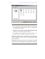
1
CONTENTS VK STEEL DESCRIPTION AND ANALYSIS OF STEEL CONSTRUCTIONS Contents ..................................................................... 1 Chapter 1.INTRODUCTION .......................................... 5 System and software requirements ................................... 6 Installation..................................................................... 6 Program Structure........................................................... 8 A first contact with working enviroment ............................. 9 General ........................................................................... 9 User interaction.............................................................. 10 The VK Steel entities....................................................... 11 Work Environment presentation ....................................... 12 Looking for Help.............................................................13 VK Steel Help System .................................................... 13 User Manuals ................................................................ 13 On Line Help ................................................................. 13 Personal Support............................................................ 15 CHAPTER 2. AN EXAMPLE ...........................................17 General.........................................................................18 Structure of the Example ................................................19 Looking for Help.............................................................20 Abbreviations ................................................................21 Step 1 Creation of the project folder................................23 Shortcut creation............................................................ 24 Step 2 Preliminary work .................................................26 Step Step Step Step Step Introduction................................................................... 26 Preliminary model definition data ..................................... 27 3 4 5 6 7 Defining the project parameters.............................32 Defining the loads and load combinations................39 Structure defining ...............................................42 Diagnostic checks ...............................................53 Members Check ..................................................56 CHAPTER 3. «FILE» MENU .........................................61 Introduction ..................................................................62 New ...........................................................................63 Open ...........................................................................65 Save ...........................................................................67 Import ..........................................................................68 Essential actions before file insertion ................................ 69 Import ASCII Format Files ............................................... 70 Import DXF Format Files ................................................. 71 Export ..........................................................................73 Export DXF Format Files .................................................. 75 Export ASCII Format Files ............................................... 77 Export Drawing .............................................................. 78 Print ...........................................................................81 Exit ...........................................................................87 Recent Projects..............................................................88 CHAPTER 4. «PARAMETERS» MENU ...........................89 General.........................................................................90 Material Library..............................................................91 Design codes ................................................................. 94 Section Library............................................................... 98 Material Properties.........................................................101 Connections..................................................................102 2 VK STEEL DESCRIPTION AND ANALYSIS OF STEEL CONSTRUCTIONS Foundation Parameters ..................................................103 Load Combinations .......................................................115 Options.......................................................................119 Fonts ...........................................................................119 Colours ........................................................................121 Visible Items.................................................................121 Show tip of the day .......................................................123 Member groups .............................................................124 CHAPTER 5. «VIEW» MENU .....................................125 General.......................................................................125 Refresh .......................................................................128 View ...........................................................................128 Members List ...............................................................128 Nodes List ...................................................................130 Nodes Loads................................................................131 Members Loads............................................................132 Quantity Estimation......................................................133 Toolbars......................................................................134 Render........................................................................135 CHAPTER 6. «EDIT» MENU ......................................139 General.......................................................................140 Undo ..........................................................................144 Copy ..........................................................................145 Paste ..........................................................................146 Delete ........................................................................147 Dynamic view ..............................................................147 New Member ...............................................................148 Mirror .........................................................................149 Select Members Window ...............................................152 Select Using Filters.......................................................153 Unselect Members ........................................................155 Select Nodes ...............................................................155 Select Nodes Window ...................................................156 Unselect Nodes ............................................................157 3D Truss .....................................................................160 3D 3D 3D 3D 3D Truss Truss Truss Truss Truss TYPE TYPE TYPE TYPE TYPE 1............................................................161 2............................................................163 4............................................................165 5............................................................167 6............................................................169 Rotation of the model around axes .................................171 CHAPTER 7. «ANALYSIS» MENU ..............................173 General.......................................................................174 Topology Check ...........................................................175 Analysis ......................................................................178 Members Check ...........................................................181 CHAPTER 8. COLUMN BASE DESIGN FOUNDATION DESIGN ......................183 General information......................................................184 Column Base Design.....................................................185 Foundation Design .......................................................191 CHAPTER 9. ELEMENTS’ PROPERTIES ......................199 VK STEEL USER’S GUIDE 3 VK STEEL DESCRIPTION AND ANALYSIS OF STEEL CONSTRUCTIONS General information on how to use toolbars.....................200 Member Properties .......................................................202 Project Library ..............................................................203 Constrains ....................................................................203 Euler Angle...................................................................204 Default Member Loads ...................................................205 Section Properties ...................................................................207 Geometry .....................................................................207 Members Loads .............................................................210 Node Properties ...........................................................211 Node Loads...................................................................211 Change Node Coordinates...............................................212 Support........................................................................213 CHAPTER 10. CONNECTION DESIGN «TRUSS» ........215 The joints program’s function ........................................216 Workpanes ...................................................................216 Members’ set up............................................................216 Welds ..........................................................................216 Flanges ........................................................................216 Rules .........................................................................217 Interventions...............................................................217 Connection Design (Truss) ............................................219 Study by VK Steel ........................................................220 Accept workpanes ........................................................222 Joint Design Weldings ...................................................223 Estimation Files............................................................227 CHAPTER 11. CONNECTION DESIGN «FRAME» .......229 “Project” Menu.............................................................230 Information ..................................................................231 Material........................................................................231 Load Combinations ........................................................232 Print Settings ................................................................233 Printout........................................................................234 Save as DXF .................................................................234 “Edit” Menu .................................................................235 Zoom in .......................................................................235 Previous Zoom ..............................................................235 Select Nodes from …to….................................................235 Deselect Nodes .............................................................236 “View” Menu ................................................................237 Toolbars .......................................................................237 Tools ...........................................................................240 Node............................................................................240 Status bar ....................................................................240 Refresh ........................................................................240 Options ..............................................................241 “Window” Menu ...........................................................243 “Connection” Menu .................................................... 244 Select node for Design Process........................................244 Select Members.............................................................244 Select Connection Type ..................................................245 Connection Editor ................................................246 Tools ...........................................................................247 “Edit” Menu (Holing) ............................................248 “Edit” Menu (Welding)..........................................252 Theory ........................................................................254 4 VK STEEL DESCRIPTION AND ANALYSIS OF STEEL CONSTRUCTIONS VK STEEL USER’S GUIDE 5 CHAPTER1 INTRODUCTION VK STEEL DESCRIPTION AND ANALYSIS OF STEEL CONSTRUCTIONS SYSTEM AND SOFTWARE REQUIREMENTS The VK STEEL program is designed for systems that are IBM PC compatible and are operating the following systems: • • • MS Windows 95/98/98 SE MS Windows NT SO4/2000 MS Windows ME Minimum system requirements • For a system operating Windows 95/95B/98/98 SE 1. Processor: Intel Pentium II 400 MHz or higher 2. System Memory: 64 MB RAM or higher 3. Storing space: At least 20 MB free hard disk space fo program installation and 200 MB for its operation. 4. CD-ROM drive: Speed 16X or higher. 5. Monitor: Resolution at least 800x600. • For a system operating Windows NT 4.0 with SP4/2000 1. Processor: Intel Pentium III 500 MHz or higher 2. System Memory: 128 MB RAM or higher 3. Storing space: At least 20 MB free hard disk space fo program installation and 200 MB for its operation. 4. CD-ROM drive: Speed 16X or higher. 5. Monitor: Resolution at least 800x600. INSTALLATION To install VK STEEL the following are required: 1. The program installation disk 2. The locking device (HASP) 6 CHAPTER 1 INTRODUCTION VK STEEL DESCRIPTION AND ANALYSIS OF STEEL CONSTRUCTIONS 3. Optionally, the detailed installation guide that can be found in the program packaging. Before you start the installation make sure of the following: • All the requirements of the unit “System and Software requirements” are met. • Your system has been booted without problems and the operating system has been loaded. • No other application is running. If there is one you have to terminate it. • The virus protection application you are using is does not forbid system files installation. Those files are installed in the c:\windows and c:\windows\system directories. (The directory names may differ, according to the options you had chosen during Windows installation). The same also applies for performance checking programs you may have. If it is seems difficult for you to accordingly modify your settings you can temporarily disable them and enable them after the installation of VK STEEL. • The locking device is firmly attached to the parallel port, on the back of the CPU box. NOTICE: The locking device installation must be carefully done and as long as you have made sure that the central unit and the printer are switched off. To install the program, follow the instructions: 1. Place the CD on the CD-ROM driver. 2. After a short while, the installation wizard will appear. 3. Follow the on-screen instructions. VK STEEL USER’S GUIDE 7 VK STEEL DESCRIPTION AND ANALYSIS OF STEEL CONSTRUCTIONS PROGRAM STRUCTURE The VK STEEL program comprises of the following parts: • • • • • Members Foundation Truss Nodes Frame Nodes Drawing MEMBERS It is the basic part of the program. In the working environment of MEMBERS you can describe your structure and calculate it. You can also check the members adequacy. The MEMBERS application is autonomous, which means that the presence of another program or another part of VK STEEL is not required. If no other parts of VK STEEL are installed then structure analysis is confined up to the members check. In other words it is not possible to check the nodes, whether it is a truss or a frame structure, or to produce drawings. FOUNDATION The FOUNDATION sub-program takes over the check and design of the column base as well as the foundation members. The structure foundation may be done either in individual bases or in a system of footings and connenecting beams. Although it is an independent program it is part of MEMBERS. TRUSS NODES The Truss Nodes sub-program takes over the check and design of truss structures nodes. It also provides the possibility to produce drawings of the structure model. To be able to check and design the nodes, the truss must be previously described in MEMBERS. To confirm that the Truss Nodes program has been installed, you have to look for the Connection Design (Truss) command in the ANALYSIS menu of the program. If the command is absent or disabled then the Truss Nodes program is not installed properly, if at all. FRAME NODES The Frame Nodes takes over the check and design of frame structure nodes. It incorporates the possibility to produce its own technical report – without reference to the one produced by MEMBERS – and connections detail drawings. To confirm that the Frame Nodes program has been installed, you have to look for the 8 CHAPTER 1 INTRODUCTION VK STEEL DESCRIPTION AND ANALYSIS OF STEEL CONSTRUCTIONS Connection Design (Frame) command in the ANALYSIS menu of the program. If the command is absent or disabled then the Frame Nodes program is not installed properly, if at all. DRAWING VK STEEL can produce and export most of the drawings that are required for the completion and validation of a project. The following table features the sorts of technical drawings that are available, depending on the program’s composition: DRAWING SORT STRUCTURE DRAWING TRUSS NODE CONNECTION DRAWING FOUNDATION DRAWING COLUMN (…) DRAWING FRAME NODE CONNECTION DRAWING VK STEEL PART MEMBERS+ NODE DRAWIMG Y Y Y FRAME NODE Y Y Y Y Table 1. Drawing creation availability depending on the composition of VK STEEL (e.g. to produce the Frame Node Connection you should have MEMBERS and FRAME NODES – the other parts of the program are not essential). All drawings processing and printing is done in an autonomous drawing program, which is installed in a separate sub-folder, in the basic STEEL program folder. To confirm that the DRAWING part is properly installed, look for the ICAD directory in STEEL. This drawing platform is based in 4M’s IntelliCAD and has similar functions with AutoCAD. A FIRST CONTACT WITH THE WORKING ENVIRONMENT. General The VK STEEL program is based on the object oriented data processing technology. The formation of the simulation to be analyzed, the graphic display of the mathematical model, is reduced to the insertion of the elements and calculation of their properties. VK STEEL USER’S GUIDE 9 VK STEEL DESCRIPTION AND ANALYSIS OF STEEL CONSTRUCTIONS Elements, for STEEL, are the nodes and members. Depending on the element type, the program forms the properties directory. The “node” object, for example, is the meeting point of the center axes of the members, so the properties directory that is formed for every such element includes geometric features (e.g. coordinates in the global coordinate system, load values that are implemented in the node coordinates). On the contrary, the “member” object represents an entity with physical essence (e.g. a steel beam of a defined length) and as it is obvious, in the properties directory physical features (e.g. steel quality, weight etc) are included. The “object-oriented” term is referred to the complete independence of each element and the possibility for the user to alter one of its attributes, without the modification of the attributes of the neighboring elements or the whole model. Thanks to this technology, apart from the easy elements input of elements and modification of their attributes, it is possible to copy, cut and paste those attributes at any time. Another important convenience is the possibility to undo an action or even a whole series of actions that have preceded. As is the case of most programs created for windows, the directory of the actions to be undone is refreshed when the file is saved. In other words, when the Save command has been chosen the possibility to undo previous actions is no longer available USER INTERACTION All work in STEEL is based on user – program interaction. The program, depending on the work stage, prepares the appropriate choices frame, in which the user should work by choosing the commands and defining the values of the parameters. Those choices commit the program in its turn to accordingly prepare for the next stage. Information exchange between the user and the program is structured in various entities, so that the procedure is simplified and the efficiency improvement. The entities that are used in STEEL are: 10 CHAPTER 1 INTRODUCTION VK STEEL DESCRIPTION AND ANALYSIS OF STEEL CONSTRUCTIONS NAME Title Bar Menu Bar Tool Bar Status Bar Project Window or Graphic Display Window Dialog Box Properties Frame Message Slide Pop-up menu Nature – Usefulness Informational. The name of the program and information on the project are included. Functional. It includes all the commands of the program, organized in menus. Functional. It includes almost all the commands of the program, organized in shortcuts (buttons). Informational - functional. Useful messages about the work stage in the Project Window appear there. It also features some commands. Informational – Functional. It features the model, in every work stage, as it is formed and saved, much information relating to the changes that are being done in it, while according to the choice, access to the most useful commands is provided, through accordingly formed pop-up menus. Functional. The program carries many different dialog boxes, different to each other, according to the functions they are destined for. It is one of the most essential tools of the interactive communication between user and program. Informational – Functional. On the one hand they feature all the properties of the object that has been chosen and on the other hand they provide the user with the possibility to modify them. Informational. It features some of the useful information on the object that has been chosen. Informational. It is the same as all other menus, only in this case it is called by right-clicking on the project window. It includes shortcuts and their content It is formed according to the object choice Table 2. Table entities and their interpretation. VK STEEL USER’S GUIDE 11 VK STEEL DESCRIPTION AND ANALYSIS OF STEEL CONSTRUCTIONS WORK ENVIRONMENT PRESENTATION Title Bar It includes the program logo as well as information on the number of the current project Graphic Display Window The model is displayed here and it is processed with the use of the graphic processing tools. 12 Toolbars They may be floating or permanently placed along the sides of the main window. They include all shortcuts (buttons) of the program commands Menu Bar All program commands are grouped I one of the menus that comprise the menu bar Message Slide According to the object choice, information is provided e.g. about the nod or the member, their number and their coordinates Status Bar Useful information about current program functions is provided Window operation keys. They are the typical WINDOWS keys for maximizing, minimizing and exiting the basic window and the current project window Horizontal and vertical sliding bars. Changing their position also moves the model through the graphic display window. Properties Frame In this frame you can search and modify the properties of the members you have chosen. The fields of the frame is automatically updated if the member choice has changed CHAPTER 1 INTRODUCTION VK STEEL DESCRIPTION AND ANALYSIS OF STEEL CONSTRUCTIONS LOOKING FOR HELP VK STEEL help system For faster familiarization of the VK STEEL program and its more efficient use, a range of aids is provided, the form and content of which will constantly be updated. The basic principal that rules the design of the help system is immediate convenience for the user with the providing of appropriate suggestions as well as answers to any problems or queries arise during the use of the program. In the following paragraphs we cite the help scheme that has been adopted. User Manuals. The best way to get acquainted and familiarized with the program is to read the current detailed user manual (which you are holding in your hands). Special effort has been given so that the book is as complete as possible in terms of content as well as appearance. The goal is the transfer of information to be achieved through a readable and tasteful text. Those requirements are covered with the implementation of PDF (Portable Document Format) technology by the Adobe company in the formation of all text files of the aforementioned titles. So apart from the printed user manuals, you also have at your disposal their files in electronic format. The great advantage of the latter is the possibility to easily update them through their version upgrade that can be achieved at any time through the web site of the 4N-VK company, (www.4m-vk.gr) without having to wait to be delivered by mail or to repeat an installation. You can get more information on those new ways (and their availability) from the site www.4m-vk.gr. On Line Help. While you are using the program you may have queries that you would like to answer without having to look the books. VK STEEL is supplied with help files of the *.chm type. NOTICE For the electronic help system to function properly you should have correctly installed Microsoft INTERNET EXPLORER. This applies to all subsequent editions of Windows 95 SE (or second edition, English or Greek). In the original edition of Windows 95, the help system will not function if Internet explorer is not installed. Moreover, there is no case for a problem to arise during VK STEEL USER’S GUIDE 13 VK STEEL DESCRIPTION AND ANALYSIS OF STEEL CONSTRUCTIONS STEEL start, which is due to the absence of essential system files of Windows. To anticipate it you should install Internet Explorer 4 or newer. Access to the ON LINE HELP system can be achieved either through the appropriate shortcut (command:INDEX) of the HELP menu, or by pressing the F1 key of the keyboard. You can look for the subject that interests you with following two ways: 1. looking for a specific article in the subject units where it is situated 2. using the search engine for words or whole phrases wherever they can be found in the articles of the help system. The help files are automatically installed in the program installation directories. Newer versions can be available without charge form the company site (www.4m-vk.gr). Looking for further help on the Internet. The supply of information and, in general, services through the Internet is a tendency that is being adopted by most large software companies. The 4M-VK company, through its web site (www.4m-vk.gr) covers VK STEEL and its users with a constantly increasing collection of various companions (small programs and documents). Among others you can find • The most recent Frequently Asked Questions (FAQ) file • Independent articles with explanation of select subjects (e.g. regulations passages, regulation implementation through the program etc) • Project examples • Presentation of notable projects that were carried out with the use of VK STEEL • Technical Report examples • Technical Drawing examples 14 CHAPTER 1 INTRODUCTION VK STEEL DESCRIPTION AND ANALYSIS OF STEEL CONSTRUCTIONS The update about the subjects and availability of this stuff will be done through the pages of the company web site. PERSONAL SUPPORT If despite all this you still have queries or problems, the 4M-VK company covers the VK STEEL program with a full support scheme. You can get more information on the terms, the way and the cost of personal support by looking at the details of the annual contracts the company can offer. Among the services that are included in personal support communication with local Authorized Dealers for all Greece, or the Programs Support for Athens for answering any queries and solving any problems. 4M-VK (Athens – Headquarters) Programs for Civil Engineers Athens: 9 Mikinon and Makedonias st, Chalandri 15233 Tel 010-6857200 Fax 010-6846237 Internet http://www.4m-vk.gr, E-MAIL: [email protected] (or the personal email addresses of each support engineer). 4M – VK (AUTHORIZED DEALERS) Thessaloniki CENTRAL MACEDONIA SILICON 75 AG DIMITRIOU STH tel. 0310-240077 fax 240077 email [email protected] & A. Petras tel 0310-323501 email [email protected] http://www.silicon.gr VK STEEL USER’S GUIDE 15 VK STEEL 16 DESCRIPTION AND ANALYSIS OF STEEL CONSTRUCTIONS CHAPTER 1 INTRODUCTION CHAPTER 2 « AN EXAMPLE » VK STEEL DESCRIPTION AND ANALYSIS OF STEEL CONSTRUCTIONS The main goal of the example that follows is the quick familiarization of the user with the working environment of the VK STEEL program. For this reason emphasis has been given to the structure definition procedure (model design), while to avoid an information overload the validation of the elements calculations is not extensively commented. In the example what is explained are the procedure of the design of a simple frame structure, its calculation, the members efficiency check according to the requirements of Eurocode 3 as well as the check and design of on of its nodes. After the completion of this example you will have • • • A quick familiarization with the most important commands and functions of this program A concise view of the work flow in the program A project example that you can use in the future, as reference Read the next paragraphs of this introduction. Their aim is to inform you on the project you intend to create, as well as the ways to look for help about operating matters, that are being covered in another part of tho user manual, or the on line help system. Specifically, • The next paragraph, STRUCTURE OF THE EXAMPLE, presents, graphically, the main steps that will be explained in the next chapters. • The LOOKING FOR HELP paragraph guides you so that you can take advantage as much as possible, of the help system, as you are working on the example • The ABBREVIATION paragraph includes a table with the printing conventions of this example. This table is an essential reference help for the understanding of the abbreviated words that are used for the sentences. 18 CHAPTER 2 “AN EXAMPLE” VK STEEL DESCRIPTION AND ANALYSIS OF STEEL CONSTRUCTIONS NOTICE We recommend before you go further to take a quick look to the INTRODUCTION chapter of the official user manual. Among others you will find a short presentation of the working environment and the features of the program. STRUCTURE OF THE EXAMPLE The procedure is structured in ten steps, organized in two units. The first unit (steps 1-7) include the actions you can do with the main part of the VK STEEL program, MEMBERS. This unit corresponds to the largest part of your work in the program, since after the completion of step 7, you will have solved the structure and have secured the efficiency of its members, according always to the requirements of the selected regulation (in our example we have selected, as Members Regulation, Eurocode 3 and as Aseismic Code, NEAK). The second unit, (steps 8-10) is mainly about nodes design, foundation check and use of the program’s results (Printings and Drawings). The program structure is the following: FIRST UNIT 1. Step 1 Introduction – Creating the project folder 2. Step 2 Preliminary work – Actions that are required before the description 3. Step 3 Defining the project parameters 4. Step 4 Defining the loads and the load combinations 5. Step 5 Structure description. Modifications and corrections 6. Step 6 Diagnostic checks and calculation 7. Step 7 Members check 8. SECOND UNIT 9. Step 8 Foundation Design 10. Step 9 Connection Design VK STEEL USER’S GUIDE 19 VK STEEL DESCRIPTION AND ANALYSIS OF STEEL CONSTRUCTIONS 11. Step 10 Results LOOKING FOR HELP This example has been designed in such way that it guides the beginner user, quickly and in a concise way in the completion of a project. For that end the references to alternative ways to the same function or more detailed explanations have been omitted. However, if you need any clarification you will need to read the printed user manual where the relevant subject is explained in more detail. For example, in STEP 3 Defining the project parameters only the parameters determination procedure is mentioned, which is needed in the project. Details on the rest of the parameter can be found in paragraph MATERIAL LIBRARY of chapter THE “PARAMETERS” MENU. An other fruitful way to look for more details is through the electronic online help system that accompanies the program. For the same subject (the “materials” and their parameters) look for details following the next procedures. Start up the program Press the [F1] key, or execute the command Help>Index (in other words select the Index command which you will find in the Help menu). The electronic help window of VK STEEL will appear. At the left side of the window you can see the tabs Contents and Search. At the center the larger window features the texts of each subject as well as the Hyperlinks between the pages. 1. FIRST WAY Select with left click the Contents tab. The list with the contents of help will appear, in hierarchical order. a. Select, with left click the subject THE PARAMETERS MENU. b. On the page, at the central window, left lick on the hyperlink “Material Library”. In the same way you can read all the units that comprise the Material Library subject, by choosing the relevant hyperlink. 20 CHAPTER 2 “AN EXAMPLE” VK STEEL DESCRIPTION AND ANALYSIS OF STEEL CONSTRUCTIONS 2. SECOND WAY. Select the Search tab. The word/phrase search engine will appear, which is part of the help system. a. At the field {Type in the keyword to find} type the word {Materials} b. Select with left click the [List Topics] button. All the page titles that include the word Materials will appear. c. To end up in the same page, as in the first way, select the title Materials and press the button [Display Topics]. Experiment with the other titles. ABBREVIATIONS No Conventions What it is for 1 File>New Program command 2 {This Project has not been saved. Are you sure?} Message Content. Text you should type 3 [CLOSE] Sign on a button 4 <DIN> Sign on a list or a field 5 LC Left Click 6 RC Right Click Comments – explanations It means that you must execute the New command, which you will find under the File menu of VK STEEL Usually the execution of a command is followed by the appearance of a message Other examples: [OK], [CANCEL] Select one of the contents of a list, after you have opened it, by clicking on the word with the left button of the mouse Abbreviation of the phrase: Click with the left button of the mouse Abbreviation of the VK STEEL USER’S GUIDE 21 VK STEEL DESCRIPTION AND ANALYSIS OF STEEL CONSTRUCTIONS 7 LDC Left Double Click 8 C:\vk\windows\steel Place of the steel folder 9 C:\vk\windows\steel\Win steel.exe 10 C:\vk\windows\steel\… Place of the Winsteel.exe file Contents of the steel folder 22 phrase: Click with the right button of the mouse Abbreviation of the phrase: Click twice with the left button of the mouse It means: The steel folder is in the windows file, which is in the VK file of hard drive c It means: The Winsteel.exe file is in the … etc It means: All the files and all the folders that are in the folder steel, which is … etc CHAPTER 2 “AN EXAMPLE” VK STEEL DESCRIPTION AND ANALYSIS OF STEEL CONSTRUCTIONS FIRST UNIT STEP 1 – CREATION OF THE PROJECT FOLDER Working with VK STEEL starts with the creation of a new project and the appropriate adjustment of the program environment. In the first step you will start up the program and create a New Project. Every new project creates a directory in C:\vk\windows\steel\meletes\… as well as a first series of essential files. The place where the program looks for the saved projects is determined and therefore you should not change it, until you have fully completed your work. If you move, for any reason, the project folder to another part of the disk, this project will not be available anymore, on the “PROJECT” dialog frame. • Follow the procedure Flow Program Start Up User Actions Start the STEEL 2001 application doing one of the following, 1. Select the WinSTEEL command from the typical Windows START>PROGRAMS> WinSTEEL menu. 2. LDC the icon that you will find on Windows desktop. (If this icon does not exist, read the notice bellow about the ways to make an , desktop) on the Windows VK STEEL USER’S GUIDE 23 VK STEEL New Project DESCRIPTION AND ANALYSIS OF STEEL CONSTRUCTIONS 3. Select the command FILE>NEW or LC the . The dialog frame {NEW PROJECT} will appear 4. With LC select the {Steel} tab and make sure that there is no other project with the same number you are about to use. 5. Select again the {New} tab and LC the {Project} icon. Press [OK] 6. On the {Steel New Project} dialog frame type the number 100 on the field {Project}, and the text {Simple frame structure} on the “Information” field. 7. Press [OK]. The program has created a directoy named {100} where all files of the 100 project will be stored. It has also formed appropriately the project window and displays the toolbars and the program menu bar. 8. RC on any icon. The TOOL BARS command will appear. Make sure that all check boxes will be checked. If any of them is not checked, then LC on the check box to select it. SHORTCUT CREATION on the Windows desktop. If a program icon has not been automatically created you can very easily create it by following the procedure bellow: 1. RC anywhere on the desktop, as long as there is no other shortcut at this place. 24 CHAPTER 2 “AN EXAMPLE” VK STEEL DESCRIPTION AND ANALYSIS OF STEEL CONSTRUCTIONS 2. On the pop up menu that will appear select the “New” command and LC on the command “Shortcut”. The “CREATE SHORTCUT” dialog frame will appear. 3. Press the button [BROWSE]. The familiar dialog frame for files browsing will appear. Look for the file Winsteel.exe, in the program folder. If during set up you didn’t change the default place of the STEEL folder, then you can look for the file at c:\vk\windows\steel\WinSTEEL.exe 4. Press the [NEXT] button. 5. Press the [FINISH] button. MOVE – COPY – COMPRESS A VK STEEL PROJECT. To move a project of the program from the directory they were saved all you have to do is move the folder with the name of the project. The same applies for copying a VK STEEL project. The compression of the project is a simple procedure as well, although it requires the existence of a relevant application. Many programs or compression algorithms allow the compression of files but not of directories. A VK STEEL project, though, does not comprise of only one file but of a group of files. This means that for the right compression you have to create first the compressed file (e.g. if you use the ZIP algorithm through an application, such as WinZip, the 100.zip file) and you have to include all the files that are included in the 100 folder of the VK STEEL project. This can be achieved with the help of the command Add to archive of the compression program. VK STEEL USER’S GUIDE 25 VK STEEL DESCRIPTION AND ANALYSIS OF STEEL CONSTRUCTIONS STEP 2 PRELIMINARY WORK – REQUIRED TASKS BEFORE THE DESCRIPTION Before we move on to the structure definition, in the program, we have to mention some comments about the tasks that are required to be done first. INTODUCTION The VK STEEL program is designed in such way that it allows any corrections that you may need to do during the model definition phase. However the best way to start your work is if you have from the start a concise view of your data and you project’s requirements. • More specifically you should 1. Have a clear view of the geometry of the structure and also of the section categories that will be used. In other words, you should bear in mind any architectural or other constraints and have checked the extent in which the structure you are about to define meets them or not. In regard to the sections, the correct choice of category will save much of your precious time. 2. Have done some kind of preliminary work in regards to the load. In VK STEEL you can input two sorts of load, a. distributed along the member, and b. concentrated , forced on the nodes. Both the distributed and concentrated on the members and nodes respectively, will have to be given in units that are according to the regulation that will be used for the design of the members. If, for example, Eurocode 3 (EC 3) is being used then the distributed load should be given in kN/m and the concentrated in kN. For the time being the program is not able to process the loads and therefore the modification of the load from kN/m2, as they emerge from the regulations, to kN/m as they have to be input distributed on the members, will have to be done by the user. 26 CHAPTER 2 “AN EXAMPLE” VK STEEL DESCRIPTION AND ANALYSIS OF STEEL CONSTRUCTIONS In this unit we will give a description of the problem that we are about to describe and solve. Some details will be given about the project data and some drawings and images in which you will be able to get as reference any time you have a query during the definition of the structure. NOTICE The regulations that will be used for the structural analysis and design of he structure are NEAK and Eurocode therefore to define the loads the relevant provisions of Eurocode 1 have been taken into account. PRELIMINARY MODEL DEFINITION DATA OF THE EXAMPLE Introduction The structure we are about to define is a simple space frame that could represent a shed. Geometry The structure comprises of two parallel frames that are connected with secondary beams. Each frame comprises of two columns of height 4 m and a pair of leaning beams with an 18.43 degrees angle from the horizontal axis. The frames are connected by parallel secondary beams that, as it is conceded, take part in the structural analysis. To avoid any unwanted relevant distortions, a pair of bracings has been placed in each leaning plane, comprising of members, which it is conceded for that they take only tension. Those members will be hollow beam of rectangular section and be connected to the main beams through brace struts. The parallel secondary beams system comprises the main mechanism of load transfer from the cover (of steel leaves of trapeze section with expectation – in the load – of future insulation), of wind pressure and sub-pressure by snow and moving loads (temporary load, as is provided by Eurocode 3 for frames with an angle less than 20 degrees). The form of the structure can be seen in the series of successive drawings and images. VK STEEL USER’S GUIDE 27 VK STEEL DESCRIPTION AND ANALYSIS OF STEEL CONSTRUCTIONS Image 1. Three dimensional model of the structure after its definition Image 2. View of the first frame 28 CHAPTER 2 “AN EXAMPLE” VK STEEL DESCRIPTION AND ANALYSIS OF STEEL CONSTRUCTIONS Image 3. Ground Plan (These images have been created with the program VK STEEL through the command Export To> Image, combined with the RENDER command Design Codes The regulations that have been followed are: • For loads: Eurocode 1 • Aseismic: NEAK • For the members: Eurocode 3 When it comes to other assumptions from the aseismic code the followig assumptions have been taken: 1. The structure is in Athens 2. The Importance of the building is Σ2 3. The soil is class B 4. The building although a frame, will be designed in elastic area (section class 3) with earthquake behavior factor q = 1.5 5. The foundation coefficient is θ = 1.0 VK STEEL USER’S GUIDE 29 VK STEEL DESCRIPTION AND ANALYSIS OF STEEL CONSTRUCTIONS 6. ζ = 3.0 % According to the assumptions above the components of the earthquake coefficient in the YX plane are Rd(T)/g x-x = Rd(T)/g = 0.31 while the activity of the vertical component of the earthquake is considered negligible. Loads For the load of the structure the following assumptions have been made: 30 • DEAD Dead load strains the secondary beams as distributed load. The main beams are being strained due to dead load only on the secondary beams base points • WIND & SUB-PRESSURE The wind’s load, for the needs of the example has been reduced to only one direction with angle α = 0. In other words the vector of the resultant of the load (that corresponds to wind pressure) has the direction of the positive Y-axis. Based on this assumption the value and direction of the distributed load has been calculated on the columns and secondary beams for the case of positive pressure (LC 4: Wind +Y) and subpressure (LC 6: Wind –Y). Because the frame does not have any draperies (or other surfaces) on a level that is vertical to the X-X axis the load of the wind in this direction has not been taken into account while, to avoid any complexity, the relevant Eurocode 1 prevision has been ignored. • SNOW For snow load the simplest case of different load has been taken, on the left and right leaning surfaces of the frame. Like in the case of wind, the load strains the secondary beams as a uniformly distributed along them. Snow load is being developed in two Load Cases: LC 8: Snow 1 and LC 9: Snow 2. • LIVE According to Eurocode 1, even in cases of nonpassable roofs, such as the case in this example, the live load for the case of repair should be taken into account. This load that will also be known as […] is taken based on the weight of the workers that will make the maintenance work. CHAPTER 2 “AN EXAMPLE” VK STEEL DESCRIPTION AND ANALYSIS OF STEEL CONSTRUCTIONS The resulting load due to frame imperfections has been ignored as negligible. Connections • COLUMNS The columns are considered to be fixed on flexible footing of cube shape, connected with inflexible beams. The support node is considered to be fixed and the assumption that there is a suitable mechanism that transfers the torsional moment to the foundation system. To make more strict the overturning check of the footing, the participation percentage of the beams (their inflexibility) of torsional moment receipt has been reduced. In terms of the frames, the nodes that connect beams to columns are considered fixed. • BEAMS The beams have been considered as fixed in terms of their connections to the columns as well as each other. • SECONDARY BEAMS The secondary beams have been considered as pinned in both sides. • ROOF BRACES We have already talked about the crosswise pairs of roof braces. We should say here that they will be defined with a buckling length that is twice the actual one to make sure that the relevant check will succeed. In practice the pair of roof braces is set up ready on the frame and consists of four members which are connected in their meeting point with a brace strut. In the program we will define those members from the node of one frame to the one on the diametrical opposite of the other frame (in other words we will define two members of each pair with length twice the actual one). VK STEEL USER’S GUIDE 31 VK STEEL DESCRIPTION AND ANALYSIS OF STEEL CONSTRUCTIONS STEP 3 DEFINING THE PROJECT PARAMETERS. On the 3rd step of the project you will select the aseismic code, the members check code and define all their relevant parameters. You will also create the Project Library having made the appropriate choices from the General Section Library that accompanies the VK STEEL program. The Project Library sections will be used later during members insertion (STEP 5). The whole parameters defining procedure will take place through the “PROJECT PARAMETERS” dialog box. • Follow the procedure PROGRAM FLOW Code Parameters defining USER ACTIONS 9. Select the command Parameters>Material Library. The {PROJECT PARAMETERS} dialog box will appear, which includes all the essential code parameters, which are organized in successive tabs. 10. Pop-up (if it is not already visible) the {CODES} tab with LC on its title. 11. On the lists {Design Codes} and {Aseismic Code} select <Eurocode (EC3)> and <NEAK> 12. Select the <Equivalent Static Analysis Eq 3.7> for the lateral seismic forces distribution 13. On <LC Factor (Live)> type {0,30} 14. On <Termal Loading Value> set to zero {0} 32 CHAPTER 2 “AN EXAMPLE” VK STEEL DESCRIPTION AND ANALYSIS OF STEEL CONSTRUCTIONS 15. Make sure that the check box <Set as Default> is not checked. On the right side of the tab make the following changes: a. Choose <Zone II> for seismic risk zone. b. Choose <S2> for category of importance. c. Choose <B> for soil class. d. Without clicking any of the {Influence Factor of Foundation} options, type <1,5> for the <q> factor value. e. Type <0,15> in the <Tx> and <Ty> fields f. Type <0,15> and <0,6> in the <T1> and <T2> fields, respectively g. Type <1,5> and <2,5> in the <Bd(0)>and <Bd(T1)> fields, respectively h. Type <0,375> in the <Bdmin> field i. Type <3> in the <Damp.Ratio> field VK STEEL USER’S GUIDE 33 VK STEEL DESCRIPTION AND ANALYSIS OF STEEL CONSTRUCTIONS j. When you are finished with all necessary changes the <Code> tab should look similar to the one illustrated in the following figure. NOTICE Defining Rd(T)/Bd(T), Rd(T)/g X-X and Rd(T)/g Y-Y is done automatically so it is not necessary to type anything on those fields. Image 4 The “Design Codes” tab after defining the parameters. 34 CHAPTER 2 “AN EXAMPLE” VK STEEL DESCRIPTION AND ANALYSIS OF STEEL CONSTRUCTIONS PROGRM FLOW Sections Selection- Project Library Creation USER ACTIONS 16. The next step is to select the sections that will be used for the structure members you are about to define. With LC select the {Section Lirary} tab. The tables that comprise your tab provide you with access to the General Sections Library, which will enable you to create the Project Library, in other words a list of the sections that will be used in your project. 17. Activate – if it is not already active – the check box next to <Fe360> and make sure that all other steel qualities are not checked. All sections you will select, from now on, will be of Fe360 steel quality. 18. Select with LC on the left side of the dialog box the IPB sections. The table in the middle will show the list of all available IPB sections along with their properties 19. With LC select the IPB200 section to select it. 20. Without moving your cursor away from the selected row, with RC pop-up the menu with the commands to insert the selected sections to the Project Library. 21. With LC select the Insert Selected Sections command. The IPB 200 section has been added to Project Library. VK STEEL USER’S GUIDE 35 VK STEEL DESCRIPTION AND ANALYSIS OF STEEL CONSTRUCTIONS PROGRM FLOW USER ACTIONS 22. Repeat process 18 –23 for the following sections, • IPE 80 • IPE 180 • IPE 220 • KT 40x40x2,6 (Square Hollow Section) 23. The Project Library creating process has been completed. Notice that the arrow next to all section types that have been selected has turned to black. Make sure that <Set as Default> (down on the left) is not checked and proceed to the next task, in the {PROJECT PARAMETERS} dialog box, which is the steel quality parameters check. NOTICE It is understandable that the selection of the Sections is dictated by the nature and function of the structure. As it was pointed in Step 2 it is essential that you have done some preliminary calculations, so that you avoid multiple tests for the selection of the appropriate sections for the structure in question and its load conditions. For this example we have selected a IPB200 section for the column which is more suitable for combined strain in axial load and biaxial pressure, while for the beams are mainly pressed elements (main and secondary) we have chosen IPE80, IPE180 and IPE220 sections. Finally, for the roof braces that act only in tension we have chosen square hollow sections. 36 CHAPTER 2 “AN EXAMPLE” VK STEEL DESCRIPTION AND ANALYSIS OF STEEL CONSTRUCTIONS PROGRAM FLOW Steel Quality Parameters Check USER ACTIONS 24. Chose with LC the {Material Properties} tab. At this point the program allows the modification of the steel quality parameters 25. Without making any changes move on to the Connections parameters Connections Parameter Check 26. Select with LC the {CONNECTIONS} tab. At this point the program allows the modification of the welds and/or bols that will be later used during nodes design. 27. Without making any changes move on to the Foundation parameters Defining the Foundation Parameters 28. Select with LC the { Foundation PARAMETERS} tab. At this point the program allows access to the foundation parameters, which are organized in sub-groups. 29. Select from this list the <[SOIL]> sub-group. With two successive LC in every field you can make the necessary changes. Make those changes a. On <Moduls of Subgrade Reaction (Ks)> type {40000} b. On <Young Moduls of Soil> type {11000} VK STEEL USER’S GUIDE 37 VK STEEL DESCRIPTION AND ANALYSIS OF STEEL CONSTRUCTIONS PROGRAM FLOW USER ACTIONS 30. Select from the list the <[MODELING]> sub-group and make the following changes: a. On <Column Perticipation Percentage> type {20} b. On < Perticipation Percentage in Tie Beam > type {60} c. On <Footing type> type {0} 31. Having completed the defining of the essential parameters and after you have made sure that <Set as Default> is not checked, press [OK]. Your program will save your selections at the parameters file of this project. 38 CHAPTER 2 “AN EXAMPLE” VK STEEL DESCRIPTION AND ANALYSIS OF STEEL CONSTRUCTIONS STEP 4 DEFINING THE LOADS AND LOAD COMBINATIONS On the forth step you will fill in the load combinations table that will be used for the classification of the stress values during the members efficiency test. Additionally you will separate the given load into member load and nodal load. Follow the procedure PROGRAM FLOW Safety factors selection and Load Combination defining USER ACTIONS 32. Select with LC the PARAMETERS>LOAD COMBINATIONS command. The Load Combinations table will open. 33. On this table, the columns represent the Load Cases while the rows represent the load combinations. Each load combination, to be valid, should include at least one load case. A load case takes part in a load combination if the table cell where the combination with load case in question meet has a value that is not zero. Those values that correspond to the Safety Factors are defined each time by the user depending on the project’s special requirements. Generally, they are given by the codes. VK STEEL USER’S GUIDE 39 VK STEEL DESCRIPTION AND ANALYSIS OF STEEL CONSTRUCTIONS PROGRAM FLOW USER ACTIONS 34. We should point here that the factors values are chosen for this project only and are not typical. 35. Type the values of the safety factors, as seen on Table 2 bellow NOTICE We should point that we fill in the load safety factor according to the regulations only in the first three and eleventh columns. In all other cases the title (e.g. Wind + X) is just indicative and you could use the column for live loads. Dead Seismic Wind Wind Wind Wind Snow Snow Other Live SeismicY Loads X +Y +X -Y -X (1) (2) Loads Loads 1 1,35 1,50 2 1,35 1,50 0,90 0,90 3 1,35 0,90 1,50 0,90 4 1,35 1,50 0,90 0,90 5 1,35 0,90 1,50 0,90 6 1,35 1,50 0,90 0,90 0,90 0,90 7 1,35 0,90 1,50 0,90 0,90 0,90 8 1,00 1,00 0,30 0,30 9 1,00 0,30 1,00 0,30 10 1,00 1,00 0,30 1,00 1,00 1,00 11 1,00 0,30 1,00 1,00 1,00 1,00 Image 5 Load combinations form and the values of the safety factors for the example project. 40 CHAPTER 2 “AN EXAMPLE” VK STEEL DESCRIPTION AND ANALYSIS OF STEEL CONSTRUCTIONS PROGRAM FLOW USER ACTIONS 36. At this point you should check the loads in relation to the load combinations you have just defined. We recommend you to compare the table above to all we have mentioned about load assumptions at STEP 2 and at the “Loads” unit. 37. The loads values that will be defined as distributed along the member, have resulted from the calculation of the weight surface in each member according to its position and angle (e.g. Outside – Inside members with an angle of the axes of the local coordinates system turned towards the load implementation level) 38. LC on [OK], to close the window. VK STEEL USER’S GUIDE 41 VK STEEL DESCRIPTION AND ANALYSIS OF STEEL CONSTRUCTIONS STEP 5 STRUCTURE DEFINING – MODIFICATIONS AND CORRECTIONS. On the fifth step you will define the elements that comprise the structure and you will modify their properties. The data insertion process is the most time consuming stage of your work. For this reason the program has many alternative ways for the most necessary parts of your work so that the formation of the structure can be simplified. In our case we have tried to describe the most possible ways. The more you use the program the more you will see that depending on the individual requirements of each structure some of the alternative ways for the same work simplify the process more than others. In other words, it is not necessary to repeat to the last word this procedure in your next project. • Follow the procedure, PROGRAM FLOW Columns Insertion USER ACTIONS 39. If you do not see the “MEMBERS PROPERTIES” toolbar make it visible. The toolbar should look like the on in Image 6 Image 6 “MEMBERS PROPERTIES” toolbar 40. Select the IPB200(Fe360) section from the <Project Library> list 41. Select the <Fixed-Fixed> option from the <Constrains> list 42. Type <90> at the EULER field 43. Select <column> in <Memmers Groups> list 42 CHAPTER 2 “AN EXAMPLE” the VK STEEL DESCRIPTION AND ANALYSIS OF STEEL CONSTRUCTIONS PROGRAM FLOW USER ACTIONS 44. LC on the icon. The {Elements Loads} dialog box appears. a. LC the <Wind +Y> option b. Select the <Local Z> axis as load axis c. Set <1,5> the <Q> value to d. Press [Update] and close the dialog box by pressing [OK] 45.RC anywhere in the project window. On the pop-up menu select WIZARD. You can select the same command from the Edit menu. The {New Member} dialog box will appear. 46. In the <Start Node> dialog box, fill in the bottom node of the column co-ordinates as follows, {1,0}, {1,0}, and {1,0}. In the <End Node> dialog box, fill in the top node of the column coordinates as follows, {1,0}, {1,0} and {5,0}. Press the [Add] button and then press [Close]. VK STEEL USER’S GUIDE 43 VK STEEL PROGRAM FLOW DESCRIPTION AND ANALYSIS OF STEEL CONSTRUCTIONS USER ACTIONS 47. Click on the icon again. The {Elements Loads} dialog box appears again. Before you do anything else, uncheck the <Wind + Y> check box. a. LC the <Wind -Y> option b. Select the <Local Z> axis c. Set the <Q> value to <1,0> d. Press [Update] and close the dialog box by pressing [OK] 48. Select the command EDIT>WIZARD Like in the previous column, on the values fields type the following: SN: {1,0}, {7,0}, {1,0} and EN: {1,0}, {7,0}, {5,0}. Press the [Add] button and then press [Close]. Defining Beams 44 49. At the {Members Properties} toolbar, make the following changes, a. Select the IPE220(Fe360) section from the <Project Library> list. b. Select the <Fixed-Fixed> option from the <Constrains> list. c. Type <0> at the EULER field d. Select <beam> in the <Memmbers Groups> list CHAPTER 2 “AN EXAMPLE” VK STEEL DESCRIPTION AND ANALYSIS OF STEEL CONSTRUCTIONS PROGRAM FLOW USER ACTIONS 50. (The beams do not bear any other load apart from the secondary beams reaction, so we will not define any load during their defining) Select EDIT>WIZARD, so that the members “New Element”dialog box. Uncheck the <Wind - Y> check box. a. LC to the [Pick] button. Select node 2 (the upper node of the left column). b. RC anywhere in the drawing window. Select the SHOW DIALOG command. c. In the <End Node> fields, type {1,0}, {4,0}, {6,0} d. LC on <Number of multiple members to insert>. In the field bellow type {3}. 51. Press the [Add] button and then press [Close]. The program has created a beam and divided it to three equal parts. 52. Select EDIT>WIZARD, so that the “New Element” dialog box appears. a. Click on the [Pick] button. Select the nodes indexed 7 and 4. b. At the < Number of multiple members to insert > field type <3> VK STEEL USER’S GUIDE 45 VK STEEL DESCRIPTION AND ANALYSIS OF STEEL CONSTRUCTIONS PROGRAM FLOW USER ACTIONS 53. Press the [Add] button and then press [Close]. NOTICE If you cannot see the numbering of members or nodes, select the command Parameters>Options>Visible. The dialog box “Visible Items” will appear. Check the options Member Names, Node Names. If the nodes themselves are not visible then you can check the Nodes option Defining the support property of the bottom column nodes 54. You will now set the start nodes of both columns to support joints. Select the command EDIT>SELECT NODES 55. Press the [Ctrl] key and keep it pressed. Select with LC the nodes 1 and 3 (the bottom nodes of the columns). The selected nodes will change their color. 56. Having selected the two nodes RC and select the SUPPORT command. The two bottom nodes of the columns will be turned into support nodes. 57. Select the command EDIT>UNSELECT NODES, to get off the Select Nodes environment. Define the second frame 46 58. You have just completed the definition of the first frame. The second frame will be defined by creating a copy of the first in a distance in the xx direction. The copy apart from the members and their geometry will also have all information relevant to the loads. CHAPTER 2 “AN EXAMPLE” VK STEEL DESCRIPTION AND ANALYSIS OF STEEL CONSTRUCTIONS PROGRAM FLOW USER ACTIONS 59. Select the EDIT>SELECT MEMBERS WINDOW command 60. LC somewhere on the left of above the structure. Release the button and move the cursor to the right and bottom, so that the window includes the entire structure. LC again. All structure members have been selected. 61. Select EDIT>COPY 62. Select EDIT>PASTE. In the appearing dialog box, type <3> to the <dx> field. The Program has copied the first frame with the loads on a distance of 3 m and created the second with its members parallel to the members of the first ones. 63. Select the command EDIT> UNSELECT MEMBERS to get off the Select Members environment Change The Structure View Point 64. LC on the icon. LC anywhere near the top node of the structure (the beams meeting point). Release the button and drag slowly the cursor to the right and bottom. Stop when you feel think that the viewpoint is satisfactory. VK STEEL USER’S GUIDE 47 VK STEEL DESCRIPTION AND ANALYSIS OF STEEL CONSTRUCTIONS PROGRAM FLOW Define Secondary Beams USER ACTIONS 65. At the {Members Properties} Toolbar, make the following changes, a. Select the IPE 180(Fe360) section from the <Project Library> list. b. Select the <Fixed-Fixed> option from the <Constrains> list. c. Type <18,43> at the EULER field. d. Select <secondary beams> in the <Members Groups> list. e. Loads (LC on the icon): <Dead>: <Global Z> with <Q> = {0,250} kN/m. <Wind + Y>: <Local Z> with <Q> = {0,70} kN/m. Check the <Snow 1>: <Global Z> with <Q> = {0,05} kN/m. Uncheck all other options. 66. LC on the icon. Make consecutive LC on the following nodes, {2,11}, {5,14}, {6,15}, {7,16} Member Load Correction 67. Because the secondary braces in the middle bear a load that is greater than the ones in the sides we will correct the loads. 68. Select the command EDIT>SELECT MEMBERS. While keeping the [Ctrl] key pressed, select members 18, 19, 20. 48 CHAPTER 2 “AN EXAMPLE” VK STEEL DESCRIPTION AND ANALYSIS OF STEEL CONSTRUCTIONS PROGRAM FLOW USER ACTIONS 69. LC on {MEMBERS LOADS} on the {SECTION PROPERTIES} frame (on the right). On the field <Load Cases> select <Dead>. Type {0.5} kN/m in the <Q> field. Select <Wind + Y> and type {1.2} kN/m. Select <Snow 1> and type {0.1} kN/m. 70. Select the command EDIT>UNSELECT MEMBERS Define the rest of the secondary beams 71. At the {Members Properties} toolbar type <-18,43> at the EULER field 72. LC the icon, to see the {ELEMENTS LOADS} dialog frame again. Uncheck all checked loads. Press [Update] and [OK]. 73. Select again the icon. Make consecutive LC on the following nodes, {8,17}, {9,18} 74. We will define the members loads with the change method. a. Select the command EDIT>SELECT MEMBERS and select members 21, 22. b. In the frame {SECTION PROPERTIES} make the {Members Loads} tab visible VK STEEL USER’S GUIDE 49 VK STEEL DESCRIPTION AND ANALYSIS OF STEEL CONSTRUCTIONS PROGRAM FLOW USER ACTIONS c. d. e. Select <Dead> and type {0.5} kN/m at <Q> on the <Global Z> Axis. Select <Wind – Y> and type {-0.9} Kn/m at <Q> on the <Local Z> axis. Select <Snow 2> and type {0.120} for <Q> on the<Global Z> axis. 75. Select the command EDIT> UNSELECT MEMBERS Secondary Beams Load Correction 76. Select the icon again. Make consecutive LC on the following nodes, {4,13} 77. We will define the members loads with the change method. 50 a. Select the command EDIT>SELECT MEMBERS and select members 23. b. In the frame {SECTION PROPERTIES} make the {Members Loads} tab visible. c. Select <Dead> and type {0.25} kN/m at <Q> on the <Global Z> Axis. d. Select <Wind – Y> and type {-0.45} kN/m at <Q> on the <Local Z> axis. e. Select <Snow 2> and type {0.06} for <Q> on the<Global Z> axis. CHAPTER 2 “AN EXAMPLE” VK STEEL DESCRIPTION AND ANALYSIS OF STEEL CONSTRUCTIONS PROGRAM FLOW USER ACTIONS 78. Select the command EDIT>UNSELECT MEMBERS Define loads through filters 79. While the structure definition has been almost completed we have not defined any live loads on the secondary beams. We will define them with the Member Selection through filters method. 80. Select the command EDIT>SELECT USING FILTERS. The dialog box of Image 7 will appear. Image 7 “SELECT USING FILTERS ” dialog box VK STEEL USER’S GUIDE 51 VK STEEL DESCRIPTION AND ANALYSIS OF STEEL CONSTRUCTIONS PROGRAM FLOW USER ACTIONS 81. In the field <According to the Group> select <Secondary Beam (Steel)> and press [OK]. The program will automatically select all the members that have been defined as secondary beams. 82. On the {Members Loads} tab select <Live> and type {1.0} kN/m at <Q>. 83. Change this value for the secondary beams to {0.5} kN/m in the way that was described in steps 69/70. Define Roof Braces 84. At the {Members Properties} toolbar make the following changes, a. Select the <KT 40x40x2,6 (Fe360)> section from the <Project Library> list b. Select the <PinnedPinned> option from the <Constrains> list. c. Type <18,43> at the EULER field. d. Select <bracing> in the <Members Groups> list. 85. Followin the procedure at 52 define the members between the nodes {5,15} and {6,14} 86. At the {Members Properties} toolbar type <-18,43> at the EULER field and repeat the procedure in step 52 for nodes {8,18} and {9,17} 87. You have just completed the model definition process.. Select FILE>SAVE to save your work. 52 CHAPTER 2 “AN EXAMPLE” VK STEEL DESCRIPTION AND ANALYSIS OF STEEL CONSTRUCTIONS STEP 6 DIAGNOSTIC CHECKS STRUCTURAL ANALYSIS Having completed the structure definition you should check its integrity and move on to the Space Frame structural analysis. The VK STEEL program provides a set of diagnostic checks to warn you about mistakes with a relevant message. On STEP 6 we will describe those two actions: Diagnostic checks and Space Frame structural analysis Follow the procedure WORK FLOW Topology Check USER ACTIONS 88. Select the command ANALYSIS>TOPOLOGY CHECK. The frame of Image 8 will appear Image 8 “Integrity Tests ” dialog box 89.On the dialog box check all options and press[OK] 90.The should not be any errors. If there is one then follow again all steps in STEP 5 VK STEEL USER’S GUIDE 53 VK STEEL DESCRIPTION AND ANALYSIS OF STEEL CONSTRUCTIONS WORK FLOW Structural Analysis USER ACTIONS 91. If nothing went wrong in the Topology Tests then you can proceed to the Space Frame structural analysis. Select the ANALYSIS>STRUCTURAL ANALYSIS command. After a few seconds a dialog frame will appear like the one in Image 9. Image 9 “Analisys ” dialog box 92. Make sure that the Analysis drive (disk) is the same with the one you have installed your program and the value of <Accidental eccentricity> is {zero}. Press [OK] Analysis Report 54 93. When the structural analysis has been completed the analysis report will appear on the screen. It should look like the one in Image 10 CHAPTER 2 “AN EXAMPLE” VK STEEL DESCRIPTION AND ANALYSIS OF STEEL CONSTRUCTIONS Image 10 The “Result Test” Screen VK STEEL USER’S GUIDE 55 VK STEEL DESCRIPTION AND ANALYSIS OF STEEL CONSTRUCTIONS STEP 7 MEMBERS CHECK After the structural analysis the relevant node displacements, and therefore the member deformations, have been calculated. In other words we have found all stress magnitude everywhere where the program will run the checks. During the checks procedure the procedure the program factorises the stress values and according to their position (e.g. beams, columns etc) will run all Eurocode 3 required efficiency tests. In case of failure the check stops and the relevant failure message will appear in a dialogue frame, citing the member and failure type. For this example we will change a part of a beam so that it fails. Follow the procedure WORK FLOW Section change for a beam (for this example only) USER ACTIONS 94. Select the command EDIT>SELECT MEMBER 95. SELECT beam 3 96. In the “Geometry” tab of the {Section Properties} frame from the Section Type list select <IPE80(Fe360)> and click on the field right bellow. The section of the beam 3 has changed from <IPE(Fe360)> to <IPE80(Fe360)> 97. Repeat the procedure we have described in STEP 6 Members Check 56 98. Select the command ANALYSIS>MEMBERS CHECK. The dialogue frame in Image 11 will appear CHAPTER 2 “AN EXAMPLE” VK STEEL DESCRIPTION AND ANALYSIS OF STEEL CONSTRUCTIONS Image 11 The “Members Design” Dialog box 99. Make the following selections, a. On the Designation unity select <Frames> and <Non Sway> b. On the Display Messages unity select <Show messages on design excess> and <New failure log File> c. Make sure the <Check all members> check box is checked 100. Press [CONTINUE] 101. After a while the program will stop and the message of image 12 will appear VK STEEL USER’S GUIDE 57 VK STEEL DESCRIPTION AND ANALYSIS OF STEEL CONSTRUCTIONS Image 12 The “Stop in Excess” window 102. The message says which member fails, where it failed the load combination during which the message appeared and the reason 103. Press [CONTINUE] 104. This time the message of Image 13 will appear. Notice that while we are still on the same member the failure is due to another reason. 105. This time select <Overcome all warning stops for all remaining members> 106. Press [CONTINUE] again. The program should not stop until the end 58 CHAPTER 2 “AN EXAMPLE” VK STEEL DESCRIPTION AND ANALYSIS OF STEEL CONSTRUCTIONS Image 13 The {Stop In Excess} window frame. This time the excess is due to member buckling on the Z-axis, because of Load Combination 2 107. After having selected the [CONTINUE] button, the program will keep on checking all members. Because you have selected <No more interruptions from all diagnosis in all members> the Members Check will not stop even if it meets some excess. This of course, does not mean that the checks do not take place. All excess messages are collected and written in a printable format file, the appearance of which notifies for the check procedure end. The excess message file will look like the one in Image 14 VK STEEL USER’S GUIDE 59 VK STEEL Correction DESCRIPTION AND ANALYSIS OF STEEL CONSTRUCTIONS 108. Press [CONTINUE]. A new window will appear, the section modification results window. The window displays the contents of the automatic section change file – it should be blank for you, since you did not use that method. Press [CONTINUE] again to complete the procedure. 109. To restore the beam you have to reset the original beam, as we have previously described and to proceed again to structural analysis and members check. Image 14 The Error Messages file (excess messages) on display window. You can print the file by selecting the [PRINT] button. 60 CHAPTER 2 “AN EXAMPLE” CHAPTER 3 «FILE»MENU VK STEEL DESCRIPTION AND ANALYSIS OF STEEL CONSTRUCTIONS Introduction The “FILE” menu is the first from the left menu. The commands that are included in the FILE menu, along with a short description, can be seen on the following table. COMMAND KEYS NEW DESCRIPTION Creates a new project OPEN Ctrl + O SAVE Ctrl + S Opens the projects directory to select an existing project Saves your project IMPORT Opens the import project from DXF or TXT files dialogue box EXPORT TO EXIT Opens the dialogue box to export the project to TXT files, create DXF drawings and get BMP or JPG form images Opens the dialogue box for the creation of the project printouts volume. Exit the program RECENT PROJECTS From the submenu you can quickly open one of the recent projects. PRINT Table 4 The commands that are included in the FILE menu. If you click on the word “File” on the menu bar the pop-up command list will appear, as seen in the following image 62 CHAPTER 3 “FILE” Menu VK STEEL DESCRIPTION AND ANALYSIS OF STEEL CONSTRUCTIONS Image 15 The FILE menu and the commands it includes. An alternative way to access the most usual commands is through the icons that are included in the FILE toolbar, as seen in the following image. Image 16 The “FILE” toolbar (floating menu) Each one of the following paragraphs is about a command and includes user directions as well as general information about their usefulness and function. If you need immediate information on a command you can take advantage of the online help system that come with the program. To open the help system press the F1 key or select the INDEX command from the HELP menu. NEW This command is for the creation of a new project. Each one of the projects of VK STEEL is stored in its own directory in c:\vk\windows\steel\meletes\… where c: the drive where the program is stored. This means that the NEW command creates a files group and not a single file. In this directory all necessary files are stored, that are created by the program during your work on the project in question. VK STEEL USER’S GUIDE 63 VK STEEL DESCRIPTION AND ANALYSIS OF STEEL CONSTRUCTIONS Additionally VK STEEL prepare the working environment by activating a new project window (new document) and all the necessary menus with the program commands. • To create a new project, follow the procedure 1. Start the program 2. Select with LC the File>New command or LC the [icon] icon. The dialogue box of image 17 will appear. Image 17 The NEW PROJECT dialogue box Image 18 The project number insertion box 64 CHAPTER 3 “FILE” Menu VK STEEL DESCRIPTION AND ANALYSIS OF STEEL CONSTRUCTIONS 3. LC the “Project” icon 4. LC on [OK] the dialogue box of Image 19 will appear. 5. Type a three-digit number of you choice between 100 and 999, on the “Project” text field. 6. You have the option to type a short comment to describe the project on the “Project Information” text field. This text will appear when you select the project (see OPEN PROJECT) 7. LC on [OK]. The program will create a new document and activate all menus. If in steps 4 or 7 you decide to cancel the process, instead of the [OK] button chose the [CANCEL] button. The program cancels all actions you have done so far. OPEN… This command enables you to open an existing project from the VK STEEL project directory. The program looks for the project directory with all relevant files that are saved in the c:\vk\windows\steel\meletes\…sub-folder and accordingly formats the project window and menu. To open a saved VK STEEL project, follow the procedure 1. Start the program. 2. Select with LC the File>Open command, or LC the The dialogue box of image 17 will appear. VK STEEL USER’S GUIDE icon. 65 VK STEEL DESCRIPTION AND ANALYSIS OF STEEL CONSTRUCTIONS Image 19 The “OPEN PROJECT” dialogue box 3. LC the “STEEL” tab. The window of image 19 will appear, with the icons of the projects that are saved in the directory \vk\windows\steel\meletes\… 4. LC the icon of the project you want. Notice that on the left window you can see the comment that is included in the project (if you had typed it during its creation). 5. LC on [OK], or the underlined text “Open the project”. The program will open the project in question and all menus. NOTICE The program can save and restore only the projects you create in this project directory. This project, like all the directories that are included in the “vk” directory, are automatically created during installation. NOTICE We recommend you not to move the projects you need immediately from the project directory of the program. However if you do it they will not be available in the program. To make them 66 CHAPTER 3 “FILE” Menu VK STEEL DESCRIPTION AND ANALYSIS OF STEEL CONSTRUCTIONS available use any copy or move method and restore it in the project directory. The copying or moving a directory does not alter their content. SAVE As with almost all programs that operate under Windows, the frequent use of the SAVE command is recommended. The reasons you have to save your work frequently are many, but the most practical value of this command is one and simple: it is the only way that minimizes the possibility to permanently lose data. • To save your work, follow the procedure. 1. LC the command File>Save or the icon NOTICE The command that is equivalent to SAVE is “Save” and not “Save As”. As it has been pointed the program cannot save in a directory other than the default one. IMPORTANT Every time you select SAVE the program frees all memory that it uses to save data and permanently saves them in the hard drive. In other words this means that you cannot anymore undo your actions. As with the other Windows programs the undo command is valid only for data that is stored in the system memory. The frequency of the use of this command is therefore relevant to your wish to save your data and to be able to undo your actions. VK STEEL USER’S GUIDE 67 VK STEEL DESCRIPTION AND ANALYSIS OF STEEL CONSTRUCTIONS IMPORT VK STEEL has an integrated graphic environment and an array of tools that allow the model’s definition. The modeling of the structure consists of the consecutive insertion of the members that comprise it, through the help of appropriate commands. This is the most usual way to define a structure. However, under some circumstances, which will be explained in this paragraph, you have the option to insert the entire structure, overriding almost the whole members insertion procedure. The principal of a structure insertion is simple: you import to STEEL a file that includes all information that is needed for the defining of a structure. You go on to defining the elements properties (members and nodes) and the defining of the codes and load parameters. The VK STEEL program provides the option to insert two types of files; • DXF format files • ASCII (TXT) format files The selection of the insert file is achieved through the dialogue box of image 20 To start the structure defining procedure form an existing file, you should do it through the options of the IMPORT dialogue box. Follow the procedure, 1. Start the program 2. Create a new project, the way it was previously described. 3. Do all actions that are described in the ESSENTIAL ACTIONS BEFORE FILE INSERTION paragraph 4. Select with LC the File>Import command. The dialogue box of Image 20 will appear. 5. Depending on the file type you want to import mark on the check box ASCII Files or DXF Files. Read the detail in the following paragraphs. 68 CHAPTER 3 “FILE” Menu VK STEEL DESCRIPTION AND ANALYSIS OF STEEL CONSTRUCTIONS Image 20 the IMPORT dialogue box. • ESSENTIAL ACTIONS BEFORE FILE INSERTION Before using the option of the program to import a structure from a file and for any file you want to use you should start a new project, as mentioned and do the following in VK STEEL: 1. Fill in he relevant parameters of the seismic code (Old or NEAK/EAK 2000) and the steel members design code (DIN or Eurocode 3). For more details on the relevant procedures read the paragraphs “Design Codes”, “Material Properties” and “Foundation Parameters” of the “PARAMETERS MENU” chapter. 2. Fill in the Project Library, the sum of the original sections that resulted from the first estimation of the structure. For more VK STEEL USER’S GUIDE 69 VK STEEL DESCRIPTION AND ANALYSIS OF STEEL CONSTRUCTIONS details read the “Section Library” paragraph of the “PARAMETERS MENU” chapter. 3. Fill in the Load Combinations table. For more details read the “Load Combinations” paragraph of the “PARAMETERS MENU” chapter. • IMPORT ASCII FORMAT FILES The ASCII format file is the simplest form of a file, since it includes information in alphanumerical characters that comprise the text or the tables, without the format parameters the text editors add, like MS WORD. Many programs that perform structural analysis on steel structures provide the option to export file of this type, which include structure members and nodes geometry parameters in table format. The goal is compatibility with other programs to the extent that is possible and to avoid additional work by repeating the time-consuming structure defining procedure. The VK STEEL program needs two ASCII format files, to fully insert he structure geometry. The one should include the coordinates of all the structure nodes, and the second one the information on members connection and, optionally, some of their properties. CAUTION Those files should strictly follow a certain composition. You can look for details about the structure of those files in the VK STEEL help system, on the chapter FILE IMPORT STRUCTURE. In case you find any differences in the files structure, you should correct them using any ASCII files processing program. Provided that you have those two files and have checked their structure, follow the procedure, 1. Follow the instruction that were described in the two previous paragraphs 2. Save the two TXT files in the project directory. It is recommended that you should chose appropriate names so that you can easily distinguish the nodes file from the members file. 3. In the IMPORT DATA dialogue box select with LC the ASCII FILES check box. 70 CHAPTER 3 “FILE” Menu VK STEEL DESCRIPTION AND ANALYSIS OF STEEL CONSTRUCTIONS 4. LC the file open icon, under “Members File Name” and look for the members file, in the project directory. 5. Repeat the procedure for the nodes file. 6. Press the [OK] button. After a while, you should be able to see your structure defined in your project window. 7. Go on to the next steps of the work flow (e.g. change the members and nodes, define loads on the members and nodes, structural analysis and members check). NOTICE The reverse procedure to the one we have just described is to export ASCII format files, which is described in detail in the EXPORT TO paragraph later in the same chapter. The program creates the two ASCII files we have described and gives you the option to transfer the geometry elements of the structure to other applications. Apart from structural analysis programs such as VK STEEL, the study of steel structures has brought out applications like MS EXCEL or LOTUS 123 into useful calculations programs. In those programs you can easily create your own spreadsheets and import with one go the structure data form the nodes and members files. • IMPORT DXF FORMAT FILES The VK STEEL program provides you the option to import DXF format drawings. This way you can draw your structure in a CAD application, such as AutoCAD or IntelliCAD and import it ready in STEEL. STEEL considers that the lines are straight members, with start and end nodes the relevant points in the lines, while for the curves there are special parameters, that have to be defined by the user, for their fragmentation into small straight members. This action is essential given that the program approximates curves with polygons. VK STEEL USER’S GUIDE 71 VK STEEL DESCRIPTION AND ANALYSIS OF STEEL CONSTRUCTIONS NOTICE There are certain restrictions in the creation of the structure drawing. During import to STEEL only entities that have been created with the LINE, POLYLINE and ARC can be recognized. If you already have a drawing in DXF format, save it in the project directory and follow the procedure, 1. Follow the instructions that were described in the “IMPORT” and “Essential Actions Before File Insertion”. 2. In the IMPORT dialogue box select with LC the DXF FILES check box. Notice that the options in the “Divide Arcs” have been activated. 3. LC the file open icon, under “Dxf File Name” and look for the members file, in the project directory 4. In the “Divide Arcs” unit select with partitions of same angle value and type the value on the field that is righjt bellow. 5. When you have finished press the [OK] button. You should be able to see your structure in the VK STEEL project window. For circular member fragmentation or in other words to approximate them with a polygon line the program provides two options NUMBER OF MEMBERS In this field you should type an integer that declare the number of straight parts that will comprise the polygon. PARTITIONS OF SAME ANGLE VALUE (DEGREES) In this field you should type the desired angle of arc to divide the curve part in elementary straight parts. The number you can type is any “reasonable” value. The program will initially try to divide the curve part in arcs with the angle you have typed and if this is not possible it will suitably adapt the value of the arc, so that the result is equal arcs. The approximation of the value is done on the nearest integer, while if the decimal part is equal to 5 to the nearest even integer. 72 CHAPTER 3 “FILE” Menu VK STEEL DESCRIPTION AND ANALYSIS OF STEEL CONSTRUCTIONS EXPORT The program provides three options to export files: 1. In (*.dxf) format, the familiar standard for drawing CAD programs (including (AutoCAD and IntelliCAD). IMPORTANT the option to export DXF format drawings is available only if the independent DRAWING program has been installed. With its installation, a new ICAD directory is created, in the main STEEL directory of the program. 2. In ASCII format files 3. In BMP or JPG format image files Generally the file export makes sense if the structural analysis has already taken place and all members have been defined. To select any of the file export formats follow the procedure 1. LC the FILE>Export command 2. The dialogue box of image 21 will appear VK STEEL USER’S GUIDE 73 VK STEEL DESCRIPTION AND ANALYSIS OF STEEL CONSTRUCTIONS Image 21 The “EXPORT ” dialogue box 3. To export DXF files use the first tab combined with the second one. For ASCII files all options are in the first tab. For image files the options can be found in the third tab. Select one of the two available options with LC on the relevant option box. 4. Fill in the necessary parameters and select [OK]. With the [CANCEL] button you simply return to the state befor the execution of the EXPORT command. IMPORTANT The option to save (Export To>*.DXF format files) (*.DXF) format files makes sense if you have already made the necessary preparation. To create a drawing file you should have the sup-programs DRAWING and NODE installed. In the “Export Drawing” paragraph, later in the same chapter, 74 CHAPTER 3 “FILE” Menu VK STEEL DESCRIPTION AND ANALYSIS OF STEEL CONSTRUCTIONS you can read about the requirements and the way to export drawing from VK STEEL. IMPORTANT The field next to the “Decimal point” index allows you to select the decimal point that will be used for the formatting of the exported files. You have two options: the comma and the point. To decide which on of the two serves your needs make sure you know how the program you are about to use for the exported file recognizes the decimal point. It would be useful, if you do already know, to confirm which of the two symbols Window itself recognizes as decimal point, since this setting is used by most of the programs (e.g. MS EXCELL). NOTICE More details on the use and parameters of each file format can be found in the paragraphs “(*dxf) format files” and “ESCII format files”. You can read about drawings in the “EXPORT DRAWING” paragraph. • EXPORT (*.DXF) FORMAT FILES The (*.dxf) file format is in fact a text file and was originally created for the communication between programs that could recognize it, with AutoCAD. This communication was and still is two-way. The generalization of its use made it the essential means to exchange data between the standard CAD programs as well as in general, between all programs that support import – export functions of this type. Most structural analysis programs like VK STEEL and several graphics and image processing applications are the most usual examples of programs that are not drawing programs. The main use of this file format for an engineer is the option to process the complex drawings of a STEEL – analyzed structure in AutoCAD. Apart from this though it is also possible to process your drawing with any other compatible program. • To be able to create and save the structure levels that you have recognized with the NODE sub-program, follow the procedure VK STEEL USER’S GUIDE 75 VK STEEL DESCRIPTION AND ANALYSIS OF STEEL CONSTRUCTIONS 1. Execute the procedure that is described in the “EXPORT DRAWING” paragraph (later in the same chapter) and after you have finished follow the steps bellow: 2. In the”Export to File” tab of the “Export ” dialogue box select with LC the “DXF” option button 3. Type a numerical value in the “Font Height” text field 4. Select which one of the colors that are available with the lists to define “Text Color” and “Entities Color”. 5. Finally, you have to define a file name and its directory in the hard drive, or other drive where it will be saved. LC in the typical file open icon in the right side of the “File Name” text field. The typical “Browse” window from Windows will appear. Type any name in the “File Name” text field and define the directory where the file will be saved. Complete by selecting [OPEN]. The file has been saved. 6. In the “Export ” dialogue box select [OK]. After a few seconds the CAD drawing application that comes with STEEL will start, where you will see the drawing of the level you have created. NOTICE The CAD program that is installed with STEEL is a full application, based on IntelliCAD. 76 CHAPTER 3 “FILE” Menu VK STEEL DESCRIPTION AND ANALYSIS OF STEEL CONSTRUCTIONS • EXPORT ASCII FORMAT FILES ASCII files are on of the simplest text forms and precisely because of this they are widely used for data transfer between different programs. Given the multitude of data processing programs with exceptional possibilities (e.g. MS Word) the ASCII format is not used for the presentation of the text itself, but for woks for which the text is required but usually not obvious to the user. An example of such work is the import of the structure nodes coordinates table to another calculations program. The co-ordinates table should be stored in an ASCII format text. NOTICE The design and check for certain connection types that for the time being are not covered by the program, can be made easier if you have the geometry of the structure’s nodes and members. You can take advantage of the option that is provided by VK STEEL, so that you can easily import the full nodes and members tables in the program you use for the connections. • To prepare and save the nodes and members files, follow the procedure 1. In the”Export to File” tab of the “Export ” dialogue box select with LC the “ASCII” option button. Notice that the parameters text fields right bellow are activated. 2. Declare with LC on the check box if you wish the members inertia properties to be included in the Members Table 3. Separately for the Nodes File and the Members File, you have to define a name and its place in the hard drive or other drive. LC in the typical file open icon at the left end of the “File Name” text field. The typical Windows “browse” window will appear. Type a name in the “File Name” text field and define where the file will be saved. VK STEEL USER’S GUIDE 77 VK STEEL DESCRIPTION AND ANALYSIS OF STEEL CONSTRUCTIONS 4. Complete by pressing [OPEN]. The file has been saved. 5. In the “Export ” dialogue box select [OK]. • EXPORT DRAWING VK STEEL provides the option to export a series of drawings in a DXF file. The creation of this file is undertaken by the DRAWING sub-program, which is not part of MEMBERS. With DRAWING you can create floor plans, view drawings etc of the whole structure or detailed drawings of the truss nodes connections. NOTICE The relevant drawings for frame nodes connections are produced and exported in DXF form by the FRAME NODES CONNECTIONS sub-program. The workpane or workpanes identification through the NODE program procedure is a condition for the creation of any drawings. Additionally the identified workpanes will have to be roughly designed, so that they are created with the commands that we will describe in this paragraph. In any case the final processing of the DXF file can take place in the independent CAD program that comes with VK STEEL. • We are outlining the diagram of the work that is required for the creation of a DXF drawing of a frame structure. 1. Defining, structural analysis, design (members check) of the frame structure. 2. Complete the structure workpanes identification and design procedure for the workpanes you want to create the drawing of, through the NODE program (for more information read the CONNECTION DESIGN (TRUSS) chapter) 3. Provided that you have identified and designed at least one of the structure levels, select the File>Export command and LC the EXPORT DRAWING tab. The dialogue box of Image 22 will appear (you can see in the image apart from the linear structure three identified levels 1, 3 and 5. This means that the structure has other levels that have not been identified by 78 CHAPTER 3 “FILE” Menu VK STEEL DESCRIPTION AND ANALYSIS OF STEEL CONSTRUCTIONS NODE and therefore there is no option to create the relevant drawings). Image 22 The EXPORT DRAWING dialogue box. 4. You can see in the dialogue box the list with the structure workpanes that have been identified. Select the one that interest you, deselect the rest (in the image we show you would select Level 1 and deselect the wireframe) and press the [CREATE DRAWING FILE] button. In the list on the left bottom make sure that the decimal point is the same with the one in the previous tab. The program will respond by making the dialogue box of Image 23 visible. 5. In the “CREATE DRAWING” dialogue box select again the level that interests you and press [CONTINUE]. 6. If it is not the first time you create the drawing then the message of image 24 will appear. Press [OK] to continue. VK STEEL USER’S GUIDE 79 VK STEEL DESCRIPTION AND ANALYSIS OF STEEL CONSTRUCTIONS Image 23 The “CREATE DRAWING” dialogue box Image 24 The message box that appears when the program detects a previous drawing with the same name. 7. In case another message appears press [CONTINUE]. A few seconds later the drawing will be created. 8. To proceed to saving and processing follow the procedure that is described in the *.DXF Format Files paragraph, from step 2. 80 CHAPTER 3 “FILE” Menu VK STEEL DESCRIPTION AND ANALYSIS OF STEEL CONSTRUCTIONS PRINT With the “PRINT” command, provided that you have completed the project, you can create the printouts volume. The general logic of the program’s printouts is adapted to the creation and export of an (*.rtf) format file so that further processing of the text with a text processing program is possible. However the final formatting of the volume will have do be done by the text editor where the (*.rtf) file will be loaded. You can create many templates and save them in the disk. You can also use more than one templates to format printout sets of the same project, e.g. a detailed and a short printout. • To create a printout template, modifying an existing one, follow the procedure icon. The 1. Select the File>Print command, or the relevant “PRINTOUT WIZARD” dialogue box of Image 2.5 will appear. 2. In the first one, in order of appearance, “SELECT A TEMPLATE” tab LC in the file open icon. The typical Windows “Browse” window will appear. Look for the “Templates” directory that is in c:\\vk\windows\steel\steelpar\templates. Select and open the “steel.tpl” file you will find in the directory. Notice in the field at the bottom the template contents will appear. This file is a ready template that is stored in the templates folder during program installation. You have the option to use this template for all your projects or to create your own template collection and store them at the same point. VK STEEL USER’S GUIDE 81 VK STEEL DESCRIPTION AND ANALYSIS OF STEEL CONSTRUCTIONS Image 25 The “PRINTOUT WIZARD” dialogue box – first tab. 3. 82 In the same tab and on the right side there are two options. Selecting “INTERNAL EDITOR” the printout file (when its formatting has been completed) will be sent to the VK STEEL text editor for further processing (e.g. page formatting, font change etc). The other option “SYSTEM RTF EDITOR” will send the printings file either to MS WORD 97/2000, or if WORD is not installed to WORDPAD. (The latter applies to most systems. If you have another text processing program, which is set as default, then the printings file will be sent to you program, provided that it can read 8.rtf format files). CHAPTER 3 “FILE” Menu VK STEEL DESCRIPTION AND ANALYSIS OF STEEL CONSTRUCTIONS NOTICE At this point we should make some clarifications on the term “TEMPLATE”. The template is not a printings file itself, but a collection of information on the formatting of many other printings files. In other words the template is the matrix document based on which is the base for the creation of every other printings document that follows it. The latter may differ in terms of content, however to have exactly the same format and include the same units. With this VK STEEL function you can, if you have two different templates, create to different printings files of the same project. 4. Select with LC the second in order tab “CREATE A TEMPLATE”. The look of the tab can be seen in Image 26. In the field on the right you can see the contents of the template, which you saw in the previous tab. On the left there are titles that while they are available they are not included in the original. Select with LC the title that interest you in the window on the lef and LC the first button (the one with the arrow that points to the right). This title will be transferred to the window on the right, which means that it will be included in the template contents. The second arrow bellow transfers all the available titles from the window on the left to the one on the right. 5. If you want to remove one of the template contents that are in the window on the right use the buttons with the arrows that point to the right. VK STEEL USER’S GUIDE 83 VK STEEL DESCRIPTION AND ANALYSIS OF STEEL CONSTRUCTIONS Image 26 The ‘PRINTOUT WIZARD” dialogue box – second tab 6. LC the “PAGE BREAK” check box to select it. Th program will place at the beginning of each unit a page break. 7. Leave the “INCLUDE ZERO VALUES” check box unchecked. On the tables that will be printed the zero values will be omitted. This will improve the appearance of the printings. 8. Select [SAVE] to save your changes in the template 9. Select the [PAGE LAYOUT] tab. The tab can be seen in Image 27. The commands that are included in the tab are the usual ones that are met in almost every text processor. Select page size, font, page orientation, format the borders and add page numbers. When you have finished select [SAVE]. 84 CHAPTER 3 “FILE” Menu VK STEEL DESCRIPTION AND ANALYSIS OF STEEL CONSTRUCTIONS Image 27 The ‘PRINTOUT WIZARD” dialogue box – third tab 10. Select the “SYSTEM VARIABLES” tab. The tab can be seen in image 28. System variables mention general information that will automatically be printed by the program. You can modify each variable’s text, by selecting it and correcting the text that can be seen in the field bellow. 11. Select the “LOAD CASES” tab. The tab can be seen in image 29. In the two fields of the tab you can select which Load Cases and Combinations will be included in your Volume. The selection can be made with LC in the relevant check box. VK STEEL USER’S GUIDE 85 VK STEEL DESCRIPTION AND ANALYSIS OF STEEL CONSTRUCTIONS Image 28 The “PRINTOUT WIZARD” dialogue box – third tab Image 29 The “PRINTOUT WIZARD” dialogue box – last tab 86 CHAPTER 3 “FILE” Menu VK STEEL DESCRIPTION AND ANALYSIS OF STEEL CONSTRUCTIONS 12. Press [OK]. The typical “SAVE AS” dialogue box will appear. Type a new name and press “SAVE”. You have created a second template, in (*.rtf) format which you can process with the help of any text processor (e.g. MS WORD), that can open files of this type. Through the text editor you can send the file to the printer. EXIT With the EXIT command the program is terminated. If there is an active project, the program examines if there are any changes to the project, which have not been saved. In case there are, the message of Image 30 will appear. Reply [YES] so that all changes are saved or [NO] if you do not want to save them. Image 30 The save changes prompt dialogue box To terminate your work and close the program, follow the procedure, 1. LC the File>Exit command or the icon. 2. If there are actions which have not been saved the message of Image 30 will appear. Reply accordingly, selecting [YES] or [NO]. 3. If you select [YES] the program will save all actions you have made until that moment and close. If you select [NO] it will go back to the state it was before you selected the command. VK STEEL USER’S GUIDE 87 VK STEEL DESCRIPTION AND ANALYSIS OF STEEL CONSTRUCTIONS NOTICE In case you selected EXIT and no non-saved actions are detected, the program will close without any other warning. ADVICE It would be useful before you decide to terminate your work, to have decided if it is worth saving the changes or the whole work. If you select to change the program without having saved the changes bear in mind that they will be lost without any possibility to restore them. RECENT PROJECTS An alternative way to open an existing project is through the selection of its three-digit number, if it is visible in the RECENT PROJECTS sub-menu. We should point here that not all available projects appear there but only the most recent ones. If the project that interests you is not among the ones that are seen in RECENT PROJECTS, then you should look for it through the OPEN command • To open one of the recent projects, follow the procedure 1. LC the File>Recent Projects commands. Hold the mouse cursor on the phrase. The directory with the recent projects will appear. 2. LC the three-digit project number that you want to select. NOTICE The default number of recent projects that appear in the sub-menu is 10. 88 CHAPTER 3 “FILE” Menu CHAPTER 4 «PARAMETERS»MENU VK STEEL DESCRIPTION AND ANALYSIS OF STEEL CONSTRUCTIONS GENERAL The second menu from the left is the “Parameters” menu. In the chart 5 that follows, you can see the commands included in this menu as well as a short presentation of those. COMMAND Material Library KEYS DESCRIPTION Opens the dialogue box “Project Parameters “ through which you can specify the parameters of the regulations and complete the “Project Library”. Load Opens the chart of Combinations “Load Options Combinations”. Leads to a sub-menu which containscontrol commands of the “window of study”functions. Language Chart 5. The commands consisted in the PARAMETERS menu. If you click on the word “Parameters” the drop-down list of commands will appear on the menu bar, as shown below: Figure 31. The PARAMETERS menu and its commands. The first two parameters are basic steps as far as the flow of the programme is concerned, whilst the third consists of commands 90 CHAPTER 4 “PARAMETERS” Menu VK STEEL DESCRIPTION AND ANALYSIS OF STEEL CONSTRUCTIONS relevant to the formation options of the elements appearing on the “window of study”. Each one of the following paragraphs is dedicated to one command and includes operating instructions as well as general information for the command’s usefulness and its function. If you need direct information about a command, you can use the electronic help system that goes along with the programme. To open the “system of help” press the F1 key or choose the command “Index” off the HELP menu. Material Library The command MATERIAL LIBRARY leads to the dialogue box of ‘Project parameters’ shown on picture 32. Picture 32 The dialogue box “Project Parameters”>”Design Codes”. In the dialogue box four tabs are accommodated, each one containing a group of parameters. These tabs are: 1. 2. 3. 4. 5. Design Code Section Library Material Properties Connections Foundation Parameters VK STEEL USER’S GUIDE 91 VK STEEL DESCRIPTION AND ANALYSIS OF STEEL CONSTRUCTIONS In the Design Codes card, you can choose the regulation of settlement of the bearing structure, the regulation of control of the structure’s members and joints and to properly modify these parameters. The Section Library card gives you the ability to choose one or more segmentations from the segmentation library of the programme as well as the quality of steel. The segmentations you have chosen as the project’s segmentations, up to that point, (one or all of these) you are going to use later in the member’s insertion. In the Material Properties card, you can modify, if this is necessary, the quality parameters of the steel. In the Foundation Parameters card, all the parameters relevant to a columns footing and the foundation system, are included. VK STEEL is capable of framed structures settlements, the columns of which are founded on a footing system (with or without connection beams) and also of structures without their foundation. In the first case it is necessary to set the values for the parameters of these cards. NOTE: In case of a structural analysis that will not include any foundation, it is necessary to define a number of SUPPORT MEMBERS. These members are auxiliary and possess inertia of such values so as to be considered practically stiff. VK STEEL symbolizes them as TYPE O members. A member can be defined as a SUPPORT MEMBER during its description, ( see NEW MEMBERS and MEMBERS WIZARD), by choosing “TYPE O” from the PROJECT LIBRARY (see ELEMENTS’ PROPERTIES> MEMBER PROPERTIES). Like the rest of the members, SUPPORT MEMBERS hold a start node and an end node. One or both of these nodes are expected to be either PINNED or FIXED ENDS. The inertia of 92 CHAPTER 4 “PARAMETERS” Menu VK STEEL DESCRIPTION AND ANALYSIS OF STEEL CONSTRUCTIONS the SUPPORT MEMBERS will not change by changing their length, which is their only modifiable dimension, meaning they are not subject to any of the sufficiency checks suggested by VK STEEL. Do not forget that the SUPPORT MEMBERS are of “theoretical” existence and they are only used in order to simulate the conditions of support. NOTE: VK STEEL is already equipped with full libraries and parameters’ files stored as all other files during the installation process. (A typical example of a library is the Section Library table). The parameters’ values and the libraries’ elements are shown on the Text fields and in the cells of the “Project Parameters” dialogue box each time a new project is started. The programme will always save a copy of the files and the libraries within your project catalogue in order to present a number of pre-determined values with every new project even if you modify/erase these values or add new elements during previous project. In case it is estimated that the parameters’ files of a certain project are corresponding more properly to your needs that the pre-determined values, you are capable of changing them by checking the check-box “Set as Default” before closing down the “Project Parameters” dialogue box. The General Parameters’ Files of the programme will be replaced by the proper ones of the current project and will appear every time you create a new project. VK STEEL USER’S GUIDE 93 VK STEEL DESCRIPTION AND ANALYSIS OF STEEL CONSTRUCTIONS DESIGN CODES The codes’ tab is usually the first one appearing after the “Parameters>Material Library” command is executed. The formation of this tab (in order to combine Eurocode regulations and NEAK regulations) is shown on figure 33. Figure 33 NEAK) “PROJECT PARAMETERS” –DESIGN CODES (EC3- • On the upper zone of the tab you can choose the appropriate code, under which the members are going to be checked and antiseismic regulation. In other words: 1. The drop-down list next to “Design Codes” indication consists of two choices: “Eurocode (EC3) and “DIN”. Choose one by taking under consideration the requirement for the structure’s and its member’s check. 2. The drop-down list next to “Aseismic” indication consists of the choices: 94 CHAPTER 4 “PARAMETERS” Menu VK STEEL DESCRIPTION AND ANALYSIS OF STEEL CONSTRUCTIONS “Old Greek Code” , “NEAK-Cypus Code” and “EAK 2000”. Choose after considering the anti-seismic requirements of the structural analysis and of the members’ check. The codes chosen are not totally independent from each other. For example, a structural analysis that is taking place at the moment (November 2002) and considers a building to be constructed has to be studied according to Eurocode 3 requirements along with the anti-seismic assumptions and methods of NEAK. If the structure under analysis was constructed e.g. in the 70’s and it is going to be subject to a sufficiency check, then we have to select “DIN” and “Old Greek Code”. NOTE: DIN-indication refers to the known German standards that were officially valid in Greece before being replaced by Eurocode 3. These regulations-codes are also known as “Method of Allowable Stresses” Figure 34 Geek Code) “PROJECT PARAMETERS-DESIGN CODES (DIN ,Old IMPORTANT The contents of the code tab will follow according to the Anti-seismic code chosen. If your choice is VK STEEL USER’S GUIDE 95 VK STEEL DESCRIPTION AND ANALYSIS OF STEEL CONSTRUCTIONS DIN Eurocode EC3, no obvious change will take place on the code tabs, but the contents of “Material Properties” tab will change. CHOICES FOR NEAK-CYPRUS CODE 1. Choose a method of distributing the horizontal seismic load. You have the following options: a. Equivalent Static Analysis -Equation 3.7(NEAK) or 3.15 (EAK) b.Equivalent Static Analysis -Equation 3.6(NEAK) or 3.14 (EAK) c. Response Spectrum Method (Gr.Code) d. Cyprus Code (Distribution of seismic load according to equation 4.2.4.1.1, paragraph 4.2.4.1 of the Cyprian Seismic Code). 3. LC Factor (Live). It is the factor of the live load’s participation the moment the earthquake is taking place. This value enters into the seismic factor’s estimation as well as into the live load’s safety factors but in seismic loading combination exclusively. According to NEAK requirements, at the time of the earthquake, we should consider that a 30% of the live load is participating. Therefore, the value usually typed is 0, 3. 4. Thermal Loading Value (Celsius)Type in the value of the suggested thermal loading in the form of temperature difference. The unit in use is Celsius degrees ºC (e.g. ∆Θ=30). • On the vertical right side of the tab you will find the antiseismic factor equation’s parameters. At this stage, the seismic factors Rd(t)g on the main directions X and Y are calculated as well as the ratio Rd(t)/Bd(t) which is irrelevant to the period (see equation 2.1 of NEAK). These parameters are analytically explained in NEAK’s chapter 2. 5. 96 Zone: the seismically dangerous zone from which factor a results automatically (factor a: soil acceleration due to gravity accelogram, see Table 2.2 of NEAK). Factor’s a CHAPTER 4 “PARAMETERS” Menu VK STEEL DESCRIPTION AND ANALYSIS OF STEEL CONSTRUCTIONS 6. 7. value in the text field comes in as an automatic consequence of your choices. Importance Factor: From this category, the factor of importance –γ- accrues automatically (Table 2.3 of NEAK). The factor’s value in the text field is calculated considering your options. Soil : We set the category of the soil on which the project is going to be realized (NEAK’s Table 2.5). NOTE: The check box under importance factor –γ- refers to a multiplying factor of Eurocode 2. In any case of a structural analysis by NEAK its value must remain 1. 8. Seizmic Behaviour Factor : we give the seismic behavior’s factor –q-, the MAXIMUM value desirable in our construction (Table 2.6 of NEAK). The value in “θ”’s text field is calculated according to your choices. 9. Influence Factor of Foundation: We give a value to the foundation’s influence factor –θ-. For soils categorized as A and B type this value is f while for soils of C type or worse we find the values from Table 2.7 of NEAK. The value in “θ”’s text field is calculated according to your choices. 10. Tx,Ty: characteristic period of the building on the x or y axis. The maximum value Rd(t) results: 11. For q≥2.5, Tx=Ty=0 whereas 12. q≤2.5, Tx=Ty=T1 13. Spectrum T1,T2 : we set values according to the soil category (Table 2.4 ofNEAK). 14. Bd(0): we set the value 9/θ 15. Bd(T1): the spectral reinforcement factor of NEAK βο= 2.5 16. Bd(min): we set the value 0,25 q/θ 17. (Τ2/Τ)β: the value of the superscript β of the equation 2.1γ for NEAK 18. Damp ratio: the percentage of critical damp. VK STEEL USER’S GUIDE 97 VK STEEL DESCRIPTION AND ANALYSIS OF STEEL CONSTRUCTIONS (Table A.1 Αnnex A of ΝΕΑΚ) The appropriate seismic factors Rdx(T)/g and Rdy/g result from the above values. CHOICES FOR THE OLD GREEK CODE 1. Uniform Distribution .It is chosen when the anti-seismic check requirements refer to the older anti-seismic code of `54-`59. 2. Triangular Distribution. It is chosen when the anti-seismic check requirements refer to the anti-seismic code of `84. 3. Seismic Comp X-X. Type straightway the value of the antiseismic factor on the X-X axis. 4. Seismic Comp Y-Y. Type straightway on the Y-Y axis. This usually has the same value as the anti-seismic factor X-X. 5. LC Factor (Live). Type the value 1, because according to older codes live loads were considered to participate 100% to the movements caused by the earthquake. 6. Thermal Loading Value (Celsius). Same as above. SECTION LIBRARY The second tab of PROJECT PARAMETERS includes the section library. Figure 35. • The second tab “Section Library” is divided in three parts: 1. The Section Type Table which is set on the left side of the screen. This table includes every section category in the section’s library of the programme. You can choose a category by left clicking on it. 2. The Section’s table which occupy’s the central and greatest part of the screen. According to the choice you made on the last table, the section’s table is formed. In other words, if you choose a particular sections’ category on this table you can see every section included in it. You 98 CHAPTER 4 “PARAMETERS” Menu VK STEEL DESCRIPTION AND ANALYSIS OF STEEL CONSTRUCTIONS can choose a section simply by clicking in one of the table’s cells. If the section you have chosen is the first of the particular category the grey arrow which is next to the category’s name in the section’s type table, turns black. Figure 35 3. PROJECT PARAMETERS-SECTION LIBRARY The three choices of steel quality, just under the sections’ table. This choice is made only by checking the check box next to the quality indication. You can choose as many of the qualities as you wish, you can even choose all of the three qualities at the same time. If you choose all three of the qualities it means that every section chosen on the sections’ table will enter three times, each time with one of the steel qualities. Generally, we suggest that you choose only one of the steel qualities each time At this point we think it is of great significance to appose two definitions in order to avoid any misunderstandings. • SECTION LIBRARY is the name of the existing file that contains the standardized sections that VK STEEL holds. A copy of this file is created in every project folder (see NEW) in order to allow the user to choose the members that will VK STEEL USER’S GUIDE 99 VK STEEL DESCRIPTION AND ANALYSIS OF STEEL CONSTRUCTIONS be used (i.e. to allow the PROJECT LIBRARY file to be created). • PROJECT LIBRARY is the name of the file that contains all the sections selected to be used in each project. It is created during the first selection of a section from the SECTION LIBRARY and it can be enriched later in another stage of the project. Besides the sections chosen from the SECTION LIBRARY, the PROJECT LIBRARY includes the SUPPORT MEMBERS as well. This file is unique for every project and it has no copy besides the one in the project’s folder. • To choose a section from the Section Library (in this case we choose IPB 360 (HEB 360) of Fe 430 quality). Follow this procedure: 1. On the sections’ tab and on the list that is set to the left sided of the tab, search for the IPB sections and click on it. The contents of the window on the right will be replaced by the table of the IPB (HEB) profiles. 2. Make sure the only steel quality that is selected is Fe 430. 3. Choose IPB 360 and click on any white cell that belongs in the same line with its denomination. The entire line will change colour (it will turn blue) which is an indication that it is selected. 4. Without moving the mouse, double click. From the fly-out menu that comes into view choose the command “Insert Selected Sections”. The IPB 360 section of Fe 430 quality is registered in the PROJECT’S LIBRARY. Observe the left window in the IPB registration. You will see that the arrow on the left has turned black which indicates that the PROJECT LIBRARY includes at least one section from the particular category. In a similar way, by repeating steps 1-4 you can add as many sections as you want in the PROJECT LIBRARY. Although there is no limit to the number of sections you can choose, it is better for your convenience to keep that number as small as possible. 100 CHAPTER 4 “PARAMETERS” Menu VK STEEL DESCRIPTION AND ANALYSIS OF STEEL CONSTRUCTIONS In step 4, in the fly-out menu, if instead of choosing the usual command “Insert Selected Sections” you choose the command “Select all”, it is obvious that all the sections of the table will be added in the PROJECT LIBRARY . (Generally we do not recommend the use of the particular command). NOTE: The steel qualities are 3 for the Eurocode EC3 and two for the allowable stresses (DIN). In other words, the formation of this part depends on the regulation selected in the first tab “Design Codes”. IMPORTANT It is not feasible to un-choose a section but this is not a problem because the PROJECT LIBRARY, the file of the programme where the selected sections are stored, can take an unlimited number of sections. Despite that, you should be cautious when choosing section so as to choose for the PROJECT LIBRARY about as many as you are going to need for your own convenience. Remember that you can add new section for the PROJECT LIBRARY any time you return to that tab. MATERIAL PROPERTIES The third tab is the Material Properties one. The contents of this tab as well, depend directly on the CODE you have chosen in the Design Code tab. For NEAK, this tab is shown on figure 36. We should point out that no change is necessary for the parameters of the steel quality. If you still wish to modify a value, in the “VALUE” column you can choose the cell of your interest by clicking on it and then click again to open the cell. The cell accepts the new value if it becomes white from grey. You can then type the value in the cell. VK STEEL USER’S GUIDE 101 VK STEEL DESCRIPTION AND ANALYSIS OF STEEL CONSTRUCTIONS Figure 36 The “PARAMETERS” dialogue box-Mateial Properties CONNECTIONS In the connections tab, the programme enables you to choose the type and the quality of the components (weldings and holings) that are going to be used later during the check and design of the connections. The Connections tab is shown on figure 37. • Follow the procedure below. 1. By clicking on the Connections you are transferred in the Parameters’ tab. 2. In the WELDINGS and BOLTS unities choose the following off the lists: a. For weldings, choose a steel quality off the CATEGORY list. You are informed about the Tensile Strenght, the Correlation Coefficient and the Weld Safety Coefficient by the values’ tables under the list b. For bolts choose a bolt category from the CATEGORY list and watch the relevant parameters. 102 CHAPTER 4 “PARAMETERS” Menu VK STEEL DESCRIPTION AND ANALYSIS OF STEEL CONSTRUCTIONS c. Choose a bolt’s dimension off the BOLT list and watch the parameters related to your choice. d. In the end, click on OK or go over to another tab of the PROJECT PARAMETERS’ dialogue box. Figure 37 The CONNECTIONS TAB FOUNDATION PARAMETERS The fifth tab is related to the parameters relevant to the soil and the foundation elements. For greater convenience the values are arranged in groups according to their relation. More precisely, these groups are • SOIL • Β.D. 1954 • Ν. Κ.O.S. • REINFORCEMENT VK STEEL USER’S GUIDE 103 VK STEEL • • DESCRIPTION AND ANALYSIS OF STEEL CONSTRUCTIONS MODELING To make one of the tabs appear so as to modify its parameters, follow the procedure below: 1. To begin, click on the Foundation Parameters to go over to the Parameters tab. 2. The top field is a choice list. Click on the arrow on the right edge of the field to open the list and select one of the groups by clicking on it. Notice that the Parameters’ names are going to change in every other field on the left as well as in the contents of the values’ fields on the right. In the following paragraphs, explanations of all parameters are given. They are divided in groups according to the sequence they follow on the list. SOIL By choosing this group, the Foundation Parameters tab is modified as shown in figure 38. • The parameters included in the SOIL group are the following 1. Soil Allowable Bearing Pressure (σ) in kg/cm2 for DIN or in N/cm2 for C.E.B. 2. Moduls of Subgrade Reaction (Ks) in T/m3 for DIN or in KN/m3 for C.E.B. This value is used by the programme for the creation of an elastic ground 3. Young Moduls of Soil in T/m2 (for DIN) or in KN/m2 (for C.E.B.) 104 CHAPTER 4 “PARAMETERS” Menu VK STEEL DESCRIPTION AND ANALYSIS OF STEEL CONSTRUCTIONS Figure 38 FOOTING PARAMETERS>SOIL tab The table below contains indicative values parameters in relation to the soil’s quality. SOIL Flabby, slack, loose Moderate Good, stable, strong Stone Σ (KN/m²) K (KN/m³) <100 10.000-15.000 ≈ 150 15.000-30.000 200-300 30.000-60.000 >400 >100.000 of the above E (KN/m²) ≈ 3.000 5.000-8.000 10.000-15.000 ≈ 25.000 Table 6 Indicative values of soil parameters (NEAK, ΝΚOS) VK STEEL USER’S GUIDE 105 VK STEEL DESCRIPTION AND ANALYSIS OF STEEL CONSTRUCTIONS SOIL Σ (T/m²) Flabby, slack, loose Moderate Good, stable, strong Stone <10 ≈ 15 20-30 >40 K (T/m³) 1.000-1.500 1.500-3.000 3.000-6.000 >10.000 E (T/m²) ≈ 300 500-800 1.000-1.500 ≈ 2.500 Table 7 Indicative values of soil parameters (Β.D.) 4. Ratio Active Area/ Total Area for Overturning check (e.g. 0, 50). We set the ratio of the active area of footing per its total area taken under consideration when the footing will be checked in over-turning. (See paragraph 5.2.3.2 (1) of NEAK). This check is valid and does not relate to the code. 5. Dynamic Moduls of Sub Rctn Ks = Coefficient x Static coeff. Certain soils behave in a different way when supporting dead loads than when supporting live loads. Therefore it is possible that the Ks taken under consideration for the analysis could be a number multiple or sub-multiple of the appropriate static e.g. saturated clay under dead load behaves as a compressed coat while in live load as an incompressible one. 6. Capacity Coefficient x Mr / Me (e.g. 1, 2). According to relation 5.2 of the 5.5.2 (2) paragraph of NEAK, this factor’s value is 1,2. In the Old Anti-seismic regulation there is no such factor which means that whatever value you set for it does not affect the checkings. Β.D. 1954 By choosing this group the FOUNDATION PARAMETERS tab is modified as shown in figure 39. • 1. 106 The parameters contained in this group are the following: Modular Ratio (n) Steel/Concrete. When the current concrete regulation is Β .D. 1954 (DIN), the Ratio equals 15 regardless of the materials quality (concrete and steel). CHAPTER 4 “PARAMETERS” Menu VK STEEL DESCRIPTION AND ANALYSIS OF STEEL CONSTRUCTIONS 2. Moduls of Elasticity of Concrete in T/m². The concrete young moduls value is given in T/m². Figure 39 3. Footings Parameters tab > Β. D. 1954 Allowable Concrete Stress in Compression (σbεπ) in kg/cm². The allowable concrete stress value is given in kg/cm². CONCRETE C16/20 C20/25 C25/30 DIN (kg/cm²) ~ 70 ~ 90 ~110 Table 8 Concrete’s allowable stress in compression, according to DIN. 4. Minimum Concrete Stress in Shear (τmin) in kg/cm². This value is given in kg/cm². Shear check of the footing is not required. VK STEEL USER’S GUIDE 107 VK STEEL DESCRIPTION AND ANALYSIS OF STEEL CONSTRUCTIONS CONCRETE DIN (kg/cm²) B160 6 B225 7 B300 8 Table 9 5. Concrete’s minimum stress in shear, according to DIN. Maximum Concrete Stress in Shear (τmax) in kg/cm². We set this value, over which we have to change the footing’s dimensions, in kg/cm². CONCRETE DIN (kg/cm²) B160 16 B225 18 B300 20 Table 10 6. Concrete’s maximum stress in shear, according to DIN. Minimum Concrete Stress in Torsion (τmin) in kg/cm². Footing’s check in tortion is not required. CONCRETE DIN (kg/cm²) B160 5 B225 6 B300 7 Table 11 DIN. 108 Concrete’s minimum stress in tortion, according to CHAPTER 4 “PARAMETERS” Menu VK STEEL DESCRIPTION AND ANALYSIS OF STEEL CONSTRUCTIONS 7. Maximum Concrete Stress in Torsion (τmax) in kg/cm². Above this value, we have to change the footing’s dimensions in kg/cm². 8. Allowable Tensile Stress of Steel (σallow) in Kg/cm2 STEEL DIN (kg/cm²) STI 1400 STIII 2400 Table 12 Steel’s allowable stress in tension, according to DIN. Ν. Κ. O.S. By choosing this group, the FOUNDATION PARAMETERS tab is modified as shown in figure 40. Figure 40 • FOUNDATION PARAMETERS tab > Ν. Κ.O.S. The parameters included in Ν. Κ.O.S.. Group are the following VK STEEL USER’S GUIDE 109 VK STEEL DESCRIPTION AND ANALYSIS OF STEEL CONSTRUCTIONS 1. Young Moduls of Concrete in KN/m². If we have chosen EC3 regulation, concrete’s pliancy counter value is given in KN/m² and depends on the concrete’s quality (Table 2.2 paragraph 2.5.2 Ν. Κ. O .S.) 2. Young Moduls of Steel in KN/m² (e.g. 20000 KN/m²). If we have chosen EC3 regulation, steel’s pliancy counter value is given in KN/m². For all steel qualities this value is 200 Gpa (paragraph 3.1.6.2 of Ν. Κ. Ω. Σ.) 3. Characteristic Concrete Compressive Strenght (FcK) in Mpa (e.g. 16) (Table 2.1 of Ν. Κ. Ω. Σ.) 4. Characteristic Steel Tensile Strenght (Fyk), in Mpa (e.g. 400) (paragraph 3.1.3 of Ν. Κ. Ω. Σ.) 5. Characteristic Tensile Strenght of Shear Reinf. (Fywk), in Mpa (e.g. 400). The value of the steel that the stirrups of the connecting beams are made of, is given in Mpa. (paragraph 3.1.3 of Ν. Κ. Ω. Σ.) 6. Concrete Partial Factor of Safety (γc): Fcd=Fck/γc. γc is concrete’s safety factor and for basic combinations or for combinations unpredictable in earthquakes, γc’s values equals 1.5, while for functionality combination, γc’s value becomes 1, according to table 6.6 of Ν. Κ. Ω. Σ. Maximum Concrete Stress= COEFFICIENT x Fcd (e.g. 0, 85). Multiplying factor of concrete’s maximum resistance. For basic and unpredictable combinations its value is 0, 85 according to paragraph 10.4.3.1 of Ν. Κ. Ω. Σ. For functionality combinations, its value becomes 0, 60 according to paragraphs 15.2 and 15.4 of Ν. Κ. Ω. Σ. 7. 8. Steel Partial Factor of Safety (γs): Fyd=Fyk/γs. For basic and unpredictable combinations in earthquakes its value is 1.15, according to table 6.0 of Ν. Κ. Ω. Σ. For functionality combinations its value becomes 2.0 according tables 6.6, 15.1 and 15.2 and paragraphs 15.2 and 15.3 of Ν. Κ. Ω. Σ. Τhis value(2.0) is taken out of tables 15.1 (for Φmax=20) and 15.2 (for maximum distance between the bars equal to 200mm) when the class of enviroment is 3 or 4 and the steel quality S400. 9. Maximum Compression Concrete Strain in Bending (e.g. 0, 0035). Concrete’s maximum deformation due to 110 CHAPTER 4 “PARAMETERS” Menu VK STEEL DESCRIPTION AND ANALYSIS OF STEEL CONSTRUCTIONS bending (proper or by axial stress, vertical or oblique) is set. Its value is set to 0, 002 according to paragraph 10.4.1δ of Ν. Κ. Ω. Σ. 10. Maximum Concrete Strain in axial compession (e.g. 0, 002). Concrete’s maximum deformation due to compression is set. Its value is set to 0, 002 according to paragraph 10.4.1δ of Ν. Κ. Ω. Σ. 11. Maximum Tensile Steel Strain (e.g. 0, 010). Reinforcement’s maximum deformation due to tension is set. Its maximum value according to paragraph 10.4.1 ε of Ν. Κ. Ω. Σ. is 0,020, but we can also set the value 0,010 that was valid before the regulations were modified in 1995 as a limit. REINFORCEMENT By choosing this group, the FOUNDATION PARAMETERS tab is modified as shown in figure 41. Figure 41 Tab: FOUNDATION PARAMETERS > REINFORCEMENT VK STEEL USER’S GUIDE 111 VK STEEL • DESCRIPTION AND ANALYSIS OF STEEL CONSTRUCTIONS Parameters included in group Reinforcement are the following In the three following parameters we define the diameters (set in mm) of the bars to be used during the foundation’s measuring. 1. Longitudinal Bar Diameter in bending mm (1st) 2. Longitudinal Bar Diameter in bending mm (2nd) 3. Longitudinal Bar Diameter in bending mm (3rd) 4. Min Bar Spacing of Longitudinal Reinf, in cm. 5. Max Bar Spacing of Longitudinal Reinf, in cm. 6. Anchorage Length for Longitudial Reinforcement = COEFFICIENT x Φmax for bars. We set a factor which multiplied by the diameter of the principal reinforcement will result in the anchorage’s length side. 7. Side Cover in cm. We set the side topping of the foundation’s reinforcement. 8. Bottom Cover in cm. We set the lower topping of the foundations’ reinforcement (see 1Table 5.1 paragraph 5.1 of Ν. Κ. O. S.) 9. Minimum Longitudial Bar diameter in Tie beams in mm. We set the minimum diameter of the bar that is going to be used for the connecting beams’ dimensions setting (paragraph 18.6.3 of Ν. Κ. O. S.). 10. Maximum Longitudial Bar diameter in Tie beams in mm. We set the maximum diameter of the bar that is going to be used for the connecting beams’ dimensions setting. 11. Min N of Longitudial Bars in Tie Beams. We set the minimum number of the connecting beams; bending bars, e.g. 3 (paragraph 18.6.3 of Ν. Κ. O. S.). 112 CHAPTER 4 “PARAMETERS” Menu VK STEEL DESCRIPTION AND ANALYSIS OF STEEL CONSTRUCTIONS 12. Minimum Link Bar Diameter in Tie Beams in mm. We set the minimum diameter of the stirrups, i.e. 10 (paragraph 18.6.3 of Ν. Κ. O. S.). 13. Maximum Link Bar Diameter in Tie Beams in mm in mm. We set the maximum diameter of the stirrups, i.e. 12. 14. Minimum Link Spacing in Tie Beams in cm (i.e. 10). 15. Maximum Link Spacing in Tie Beams in cm (i.e. 15) (paragraph 18.6.3 of Ν. Κ. O. S.). MODELING By choosing this group, the FOUNDATION PARAMETERS tab is modified as shown in figure 42. Figure 42 FOUNDATION PARAMETERS > MODELING TAB VK STEEL USER’S GUIDE 113 VK STEEL • DESCRIPTION AND ANALYSIS OF STEEL CONSTRUCTIONS The parameters included in group Β.D. 1954 are the following 1. Footing Cone Hmin/Hmax = 1/ FACTOR (i.e. for ½= 2). It is valid for stiff footings. The factor equals the ratio of the entire height of the footing to the height of the rectangular part. (Form Σ18.29 of comments paragraph 18.6.2 of Ν. Κ. O. S.). 2. Minimum Height of Cone Base in Conical Footing in cm. We set the minimum height we wish to the rectangular part of the foundation (base of the cone). 3. Maximum Height of Cone Base in Conical Footing in cm We set the minimum height we wish to the rectangular part of the foundation (base of the cone). 4. Footing Min Height cm. 5. Footing Type (1=Cone Ftng 0=Rectangular Ftng). We set the type of footing. Cone-based footings are considered stiff, while box-based footings are considered flexible. 6. Column Perticipation Percentage (0-100%). We set the percentage of a footing’s moment of torsion that a column is taking-up. 7. Column Top (1=Fixed 0=Pinned ). We define the column’s top as a fixed end or a pinned end. 8. Tie Beams (1=Top 0=Bottom) We determine the connecting beams’ position. They are set on the neck or on the ground. 9. β= COEFFICIENT x Vcd , COEFFICIENT (i.e. 2,50). Factor β is necessary to overcome certain practical problems. By Ν. Κ. Ω. Σ., concrete’s resistance in shear is very decreased compared to concrete’s resistance according to the allowable stresses’ regulation. (I.e. for C16 the “allowable stress” value is Vcd = 2,2 kg/cm² while for B225 Vcd = 8 kg/cm². This can be surpassed by increasing Vcd with a multiplying factor β. 114 CHAPTER 4 “PARAMETERS” Menu VK STEEL DESCRIPTION AND ANALYSIS OF STEEL CONSTRUCTIONS 10. Max acd. We set the magnification capacity factor’s (acd) maximum value that we want to join in the calculation. The programme will consider in its calculations the smaller values between the behaviour factor q which is given on the calculation’s box of the anti-seismic factor and the maximum value of the acd that you are going to give in the foundation model parameter’s group. 11. Participation Percentage ly Tie Beam (0-100%). Set the percentage of the connecting beams’ torsional inertia which serves to prevent footings from overturning. LOAD COMBINATIONS The command leads to the load combination’s definition table. The programme will check the member’s sufficiency based on these combinations. • For the load combinations table to emerge, follow the procedure below: 1. By clicking on the “Parameters > Load combinations” command, the table shown on figure 43 will appear. Figure 43 “LOAD COMBINATIONS” dialogue box VK STEEL USER’S GUIDE 115 VK STEEL DESCRIPTION AND ANALYSIS OF STEEL CONSTRUCTIONS The LOAD COMBINATION window is basically a large table divided in two parts. The table’s lines constitute the loading combinations and the columns constitute the loading cases. In the upper part of the table that has a white background, you can determine the loading combinations by simply typing the safety factors in the appropriate cells. As you will notice certain factors are already filled in. The programme offers the basic loading combinations which are required in the majority of projects as by definition values. If you find it necessary it is possible to correct the safety factors’ values or even add more factors to the existing ones. Start from the first free line of the table and add values in the appropriate cells. In the lower part of the table that has a green background, the programme presents the additional loading combinations that are performed automatically. It is not feasible for the user to interfere with those cells’ contents. The lines of this table which represent the loading combinations are numerated by serial numbers, each of these numbers characterizing particular combination. The columns of the table which represent the loading cases are characterized by the name written on the columns nameplate. 116 CHAPTER 4 “PARAMETERS” Menu VK STEEL DESCRIPTION AND ANALYSIS OF STEEL CONSTRUCTIONS • More specifically, the 12 loading cases accepted by the programme are the following:+ Seismic Vertical Component S.N. (Serial No) TYPE INTERPRETATION 1 DEAD LOADS Static loading due to dead loads. It will also be used to automatically estimate the seismic loads. 2 SEISMIC Y Seismic loading parallel to the Y axis 3 SEISMIC X Seismic loading parallel to the X axis 4 WIND + Y Wind-loading parallel to the Y axis of the general system on the positive direction. 5 WIND +X Wind-loading parallel to the X axis of the general system on the positive direction. 6 WIND - Y Wind-loading parallel to the Y axis of the general system with a negative direction 7 WIND – X Wind-loading parallel to the X axis of the general system with a negative direction 8 SNOW (1) Loading due to snow (1st case) 9 SNOW (2) Loading due to snow (2nd case) 10 OTHER LOADS Loading of non specified name subject to use according to the project’s needs. 11 LIVE LOADS Loading due to live loads. It is going to be used for the automatic calculations of the seismic loads. 12 THERMAL Thermal-loading (automatic calculation) Table 13 STEEL’S loading cases The participation rule for every loading case in a loading is very simple: if the value within the appropriate cell is zero, the VK STEEL USER’S GUIDE 117 VK STEEL DESCRIPTION AND ANALYSIS OF STEEL CONSTRUCTIONS corresponding loading case does not participate. If the value within the cell is other than zero, the loading case it refers to will participate to the loading combination. ATTENTION According to the regulation, the value of the safety factor for each loading case is always different NOTE (For the Allowable stresses regulation). Each combination is characterized as –H- or –HZ- in the last column (H=0, HZ=1). Dead Seismic Wind Wind Wind Wind Snow Snow Other Live SeismicY Loads X +Y +X -Y -X (1) (2) Loads Loads 1 1,35 1,50 2 1,35 1,50 0,90 0,90 3 1,35 0,90 1,50 0,90 4 1,35 1,50 0,90 0,90 5 1,35 0,90 1,50 0,90 6 1,35 1,50 0,90 0,90 0,90 0,90 7 1,35 0,90 1,50 0,90 0,90 0,90 8 1,00 1,00 0,30 0,30 9 1,00 0,30 1,00 0,30 10 1,00 1,00 0,30 1,00 1,00 1,00 11 1,00 0,30 1,00 1,00 1,00 1,00 Table 14: Load combinations’ table. Note that the value of the safety factors varies, according to the bearing structure. On the table the loading case 12 does not appear since it does not participate in any loading combination. 118 CHAPTER 4 “PARAMETERS” Menu VK STEEL DESCRIPTION AND ANALYSIS OF STEEL CONSTRUCTIONS INDICATION If you wish to add a loading combination on the table above, you have to start from line 10 (which is not obvious on this table but only on the corresponding one of the programme). In addition, in case you leave a vacant line – a line on which all safety factors’ values in all the cells that belong to this line are zero- then all the loading combinations below this line will not be considered during the dimension set performed by the programme. OPTIONS The command “OPTIONS” leads to a sub-menu where the following commands are found: 1. Fonts 2. Colours 3. Visible Items 4. Show Tip of the Day 5. Member Groups 6. Toolbars Each one of these leads to a dialogue box consisting of a number of options. All of the above commands refer to auxiliary functions and relate to the development of the text or even of the whole programme and they are not considered as an essential step of the programme’s flow. In the following paragraphs you can find information for each one of these commands and their function. FONTS • To change the type of lettering used by the programme to create a text, follow this procedure: 1. Choose the Parameters > Options >Fonts command. The dialogue box shown in figure 44 will appear. VK STEEL USER’S GUIDE 119 VK STEEL Figure 44 DESCRIPTION AND ANALYSIS OF STEEL CONSTRUCTIONS The “FONTS” dialogue box The appearing dialogue box is the windows’ typical one. Choose OK to confirm a choice or CANCEL to return to your previous settings. 120 CHAPTER 4 “PARAMETERS” Menu VK STEEL DESCRIPTION AND ANALYSIS OF STEEL CONSTRUCTIONS COLOURS • To change the colours of the elements (e.g. joints, members etc.) on your screen follow this procedure: 1. Choose Parameters > Options >Colours command. The dialogue box shown on figure 45 will appear. Figure 45 “COLOURS” dialogue box There is a drop-down list related to each one of the indications (i.e. Members, Chosen Members etc.). Open one by left clicking on its arrow and simply choose the colour you prefer. VISIBLE ITEMS This option is probably the most useful one because it is related to whether several elements of the bearing structure will appear on the screen or not. The ability to hide information will be very useful in cases of complex or large structures. VK STEEL USER’S GUIDE 121 VK STEEL DESCRIPTION AND ANALYSIS OF STEEL CONSTRUCTIONS • To choose which of all the elements will stay visible, follow the procedure: 1. Choose Parameters > Options> Visible Items command. The dialogue box shown in figure 46 will appear. Figure 46 “VISIBLE ITEMS” dialogue box On the upper part of the dialogue box you can choose whether all the members of the structure will be visible or only the ones selected. You can select members by using one of VK STEEL’S appropriate commands which are analytically presented in the chapter “EDIT MENU”. On the left middle part you can choose which one of the elements’ categories you wish to remain visible by checking on the appropriate check-boxes. On the right middle part you can choose the schematic diagram of the loading case you wish to be shown. But it is necessary that you first check on the check-box “Members(Nodes) Loads”. If this 122 CHAPTER 4 “PARAMETERS” Menu VK STEEL DESCRIPTION AND ANALYSIS OF STEEL CONSTRUCTIONS check-box is not chosen, then no schematic diagram of any loading case will be shown. On the lower part of the dialogue box there are two parameter options related to the way the programme makes the bearing structure appear when deformed. You can modify the Multiplicaton factor or the Maximum displacement to attain a better view of the structure and then check the result on you screen. As before, these fields are activated if the option “Deformed Frame” on the left middle window is checked. Otherwise, the schematic depiction of the deformed bearing structure will not be visible. Show Tip of the Day By choosing the Parameters > Options >Show Tip of the Day command, the dialogue box shown on figure 47 appears on your screen. Figure 47 “Tip of the Day” dialogue box This dialogue box appears each time you start the programme and contains a number of useful advice. It consists part of the programme’s helping facilities. If you wish that the “Tip of the Day” dialogue box does not appear each time the programme starts, check on the check-box “Don’t show tips at start up”. VK STEEL USER’S GUIDE 123 VK STEEL DESCRIPTION AND ANALYSIS OF STEEL CONSTRUCTIONS MEMBER GROUPS Each group takes its name according to the position its members have within the structure. By using this command you are able to modify the –by definition- names used by the programme and replace them by the ones you choose. • To replace the by definition names of the groups, follow the procedure: 1. Choose Parameters > Options > Member Groups names command. The dialogue box shown on figure 48 will appear. 2. Replace the name of each group by typing the one you prefer on the appropriate line. 3. Choose –OK- or –CANCEL- to confirm or cancel your actions. Figure 48 “Member Groups” dialogue box 124 CHAPTER 4 “PARAMETERS” Menu CHAPTER 5 « V I E W» M EN U VK STEEL DESCRIPTION AND ANALYSIS OF STEEL CONSTRUCTIONS General The “View” menu is the third from the left on the γραµµη µενου. The commands that this menu contains as well as a short description of those are shown on Table 15 below. COMMAND REFRESH KEYS Ctrl + R VIEW MEMBERS LIST NODES LIST NODES LOAD DESCRIPTION Refreshes the contents of the study window. It is usually used after corrections. It allows the user to choose one of the structure’s pre-selected view- points. Informative. It shows in the form of a table the properties of the sections already described Informative. It shows in the form of a table the properties of the joints already described. Informative. It shows in the form of a table the load taken by the sections which have already being described MEMBERS LOADS QUANTITY ESTIMATION MOVE TOOLBARS Shows a pre-calculation of the materials table. It allows the adaptation of the workspace. RENDER It shows the geometry of the section of a certain member of a group of members Table 15 The VIEW menu and its commands 126 CHAPTER 5 “VIEW” Menu VK STEEL DESCRIPTION AND ANALYSIS OF STEEL CONSTRUCTIONS If you click on “VIEW “the drop-down list of the commands will appear on the menu bar, as shown below Figure 49 The “VIEW” menu and the commands it contains An alternative way to access the most useful commands is through the icons of the EDIT toolbar shown below. Figure 50 Some of the commands consisting the “VIEW” menu are included in the EDIT toolbar. Each one of the following paragraphs is dedicated to one command and contains operation instructions as well as general information for its usefulness and its function. If you need direct information about a command you can take advantage of the electronic help system provided with the programme. To access this system, press F1 or choose the INDEX command from the HELP menu. VK STEEL USER’S GUIDE 127 VK STEEL DESCRIPTION AND ANALYSIS OF STEEL CONSTRUCTIONS REFRESH This command redraws the content of your workspace. It is of the same use as the REFRESH command of the WINDOWS or the “REDRAW’ and “REGEN” commands of AutoCAD. Use this command in case you think that certain elements are not shown properly on the screen. VIEW The “VIEW” command leads to a sub-menu which contains the following commands: 1. XY 2. XZ 3. YZ These commands show the bearing structure from a view-point corresponding to the chosen plane. IMPORTANT The plane that appears with the start of the programme (the by-definition plane) is YZ. The semi-axis Z takes positive values upwards and the semi-axis Y takes positive values towards the left. X-axis takes its positive values directed towards the screen, opposite to the user. • To watch the structure in one of the XY, XZ and YZ planes follow the procedure: 1. Click on the SHOW > NEW > XY (or XZ, YZ) command or the appropriate icons. The corresponding aspect of the structure will appear on the screen. MEMBERS LIST An important facility provided by VK STEEL is the appearance of the elements of the members that have been described in the form of a table. 128 CHAPTER 5 “VIEW” Menu VK STEEL DESCRIPTION AND ANALYSIS OF STEEL CONSTRUCTIONS This table though, is of properly informative use. By using this table you are able to find a member’s (or several members’) identity very quickly since these are arranged next to their serial number on a table. • To make the table appear follow the procedure: 1. Choose Members List command. 2. Use the sliding bar if the table is large. When ready, click OK to close the window. An indicative picture of the table is shown on figure 51. Figure 51 MEMBERS LIST VK STEEL USER’S GUIDE 129 VK STEEL DESCRIPTION AND ANALYSIS OF STEEL CONSTRUCTIONS NODES LIST As in members’ list, the NODES LIST command presents joints’ elements arranged on a table. • To make the NODES LIST show up follow the procedure: 3. Choose NODES LIST command. 4. If the table is too large use the sliding bar. When you finish click on OK to close the window. The NODES LIST is shown on figure 52. Figure 52 NODES LIST 130 CHAPTER 5 “VIEW” Menu VK STEEL DESCRIPTION AND ANALYSIS OF STEEL CONSTRUCTIONS NODES LOAD The NODES LOAD command presents the load taken by the joints arranged on a table. This table, as every table in VIEW MENU is of informative character. No change made on the table will be taken under consideration by the programme. You can change the loads taken by the joints only through the procedure of their description (see ELEMENTS’ PROPERTIES paragraph NODE PROPERTIES). • To make the NODES LOAD appear on the screen follow the procedure 1. Choose View > NODES LOAD command. 2. If the table is too large use the sliding bar. When you finish click on OK to close the window. The NODES LOAD table is shown on figure 53. Figure 53 NODES LOAD table VK STEEL USER’S GUIDE 131 VK STEEL DESCRIPTION AND ANALYSIS OF STEEL CONSTRUCTIONS MEMBERS LOADS The MEMBERS LOADS command presents the data of the load taken by the members of the structure in the form of a table. The description of these loads takes place either during the description of each particular load or after this description, through the procedure of changing the members’ properties (see chapter ELEMENTS’ PROPERTIES paragraph Member Properties). • To make the MEMBERS LOADS table appear on the screen, follow the procedure 1. Choose View > Members Loads command. 2. If the table is too large use the sliding bar. When finished click on OK to close the window. The Members Loads table shown on figure 54. Figure 54 MEMBERS LOADS table 132 CHAPTER 5 “VIEW” Menu VK STEEL DESCRIPTION AND ANALYSIS OF STEEL CONSTRUCTIONS QUANTITY ESTIMATION VK STEEL provides you with the ability to quickly pre-calculate the quantity of the materials to be used for the structure’s members, described up to the moment you choose the command. Always keep in mind that these calculations are approximate and in case you need greater precision you must search for the pre-calculation tables resulting from the dimensions set of the structure’s members. • To make the Quantity Estimation table appear on the screen, follow the procedure 3. Choose View> Quantity Estimation command. 4. If the table is too large use the sliding bar. When finished, click on OK to close the window. Quantity Estimation table is shown on figure 55. Figure 55 QUANTITY ESTIMATION table VK STEEL USER’S GUIDE 133 VK STEEL DESCRIPTION AND ANALYSIS OF STEEL CONSTRUCTIONS TOOLBARS Show Toolbars command allows you to choose which toolbars (or fly-out menus) will constantly appear on the screen while working on the programme. • To show or hide toolbars follow these steps 1. Right click on View > Toolbars command. The dialogue box shown on figure 56 will appear. Figure 56 “TOOLBARS” DIALOGUE BOX TOOLBARS’ dialogue box consists of a number of choices equal to the number of the independent toolbars. If the check-box next to each toolbar’s name is checked, the particular toolbar will show on your screen in its position or in the position it was left the last time the programme was used. If its check-box is not checked, the toolbar will not show. NOTE: These toolbars’ by definition position is below the menu bar. Alternative positions are the left and right side margins of the study window. You can move a toolbar by keeping the left key of the mouse pressed over the double vertical bar of the toolbar and then move it towards the left or right margin of the study window. When you have found the position you wish, stop pressing the key of the mouse. If you do that while in the study window, the toolbar becomes a fly-out menu. Its title is shown on the top of the toolbar. To remove a fly-out menu, follow the same steps with 134 CHAPTER 5 “VIEW” Menu VK STEEL DESCRIPTION AND ANALYSIS OF STEEL CONSTRUCTIONS the only difference that the mouse’s indicator should be over the menu’s title zone. By clicking on OK, you confirm the changes you have made. RENDER It is extremely important for the correct structural analysis of a model as well as for the code check of the members and the connections to precisely define the rotation angle of the profile’s axis around the length axis. This angle is widely known as EULER angle, an appellation adapted by VK STEEL while in the international bibliography it is referred to as BETA or GAMMA angle. NOTE: You can find out more about the EULER angle in the paragraph name by the angle of the “Members’ Properties” unity of the “ELEMENTS’ PROPERTIES” chapter. It is necessary for the user to understand this concept thus we recommend that you spend some time on it for your facilitation. The RENDER command is used for the repousse representation of the members’ morphology which is not possible through the entire procedure of members’ description. NOTE: The 3-D representation of values and surfaces is generally one of the most demanding operations for the processor and the graphics’ accelerator. Even today’s PCs are testing their limits in cases of complex solids which require high quality of representation. By presenting members in that way you can easily verify EULER angle’s value for a member or a group of members. In other words, by using this command, you can attain a satisfying representation of the arrangement of the members within a part of the structure and, if necessary, to modify the value of the angle. • To check the EULER angle of a member or a group of members follow the procedure 1. By using the Edit > Select Members command, pick member or group of members you are interested in. the picked members will appear in a different colour. VK STEEL USER’S GUIDE 135 VK STEEL DESCRIPTION AND ANALYSIS OF STEEL CONSTRUCTIONS 2. Choose View > Render command. By clicking on Render you will notice that it stays pressed which indicates the Render situation. In the study window you will also notice that the chosen members appear with their section set on an angle equal to the one you have inserted during their description. 3. Continue to select members. For each one you choose, its profile’s position in space will appear on the screen. You can also use the appropriate commands to change viewpoint in combination with the screen Refresh command until you achieve the most satisfying result. 4. To escape the RENDER situation you only have to re-click on RENDER through the View menu. NOTE: RENDER is basically used to check and correct the EULER angle. In case you wish to correct this angle while you are still in rendering, you have to choose View > Refresh or press ctrl + r to see the new, corrected position of the member. The programme will refresh all the contents of the study window including the EULER angle which is modified. 136 CHAPTER 5 “VIEW” Menu VK STEEL DESCRIPTION AND ANALYSIS OF STEEL CONSTRUCTIONS EXAMPLE In the following figures 57 and 58 you can see a group of members before and after rendering. Figure 57 The chosen group of members before rendering Figure 58 The same group after rendering. VK STEEL USER’S GUIDE 137 VK STEEL 138 DESCRIPTION AND ANALYSIS OF STEEL CONSTRUCTIONS CHAPTER 5 “VIEW” Menu CHAPTER 6 « E D I T» M E N U VK STEEL DESCRIPTION AND ANALYSIS OF STEEL CONSTRUCTIONS General The “EDIT” menu is the third from the left on the menu bar. It contains all the commands of description and EDIT of the structure. Generally, you can access these commands either through the title bar or through the menu bar or even through the pop-up menu which becomes active after you right click anywhere outside the study window. The commands included in “EDIT” menu as well as a short description of those are presented on the following table 16. COMMAND UNDO KEYS Ctrl+Z DESCRIPTION Cancels the previous command. It is also working even if the previous command was a member’s insertion COPY Ctrl+C Creates copies of selected entities or of the entire content of the workspace into clipboard. PASTE Ctrl+V Transfers the contents of clipboard within your workspace. DELETE Ctrl+Del Deletes the selected entities. SPLIT REBUILD DATABASE DYNAMIC VIEW Check the model’s rotation. NEW MEMBER Displays New Member 140 CHAPTER 6 “EDIT” Menu VK STEEL DESCRIPTION AND ANALYSIS OF STEEL CONSTRUCTIONS dialogue box MIRROR SELECT Uses a selected plane as a mirror to create the reflection of a chosen entity (or even a number of entities). MEMBERS Allows the user to choose an entity or a group of entities. SELECT MEMBERS Allows you to choose entities by WINDOW using a window. SELECT Allows you to select entities according to attributes determined by the user. USING FILTERS UNSELECT MEMBERS Cancels the selection of entities you have previously selected. SELECT NODES Allows you to choose joints. SELECT NODES WINDOW Allows you to select joints by using a window. UNSELECT NODES Cancels you previous selection of joints. WIZARD Insert members using the wizard. 3D Truss Displays the wizard for inserting space structures. Table 16 by EDIT menu and its contents. If you click on EDIT, a drop-down list of the commands reported above will emerge from the menu bar. VK STEEL USER’S GUIDE 141 VK STEEL Figure 59 DESCRIPTION AND ANALYSIS OF STEEL CONSTRUCTIONS EDIT menu and its commands You can access these commands directly through the icons which consist the EDIT, EDIT II and WIZARD toolbars (see below). Figure 60 “EDIT” toolbar and its consisting commands. Some of the commands belong to VIEW menu while other ones (like Zoom In and Zoom Out) are not included in any of the menus. Figure 61 142 “EDIT II” toolbar and the commands it contains. CHAPTER 6 “EDIT” Menu VK STEEL DESCRIPTION AND ANALYSIS OF STEEL CONSTRUCTIONS Figure 62 “WIZARD” toolbar and the commands it contains. A simpler way to access a command of the EDIT MENU, is through the two pop-up menus that will appear on your screen if you right click inside the study window. By right clicking anywhere but on a joint, the pop-up menu shown below will appear on the screen. Figure 63 “EDIT” pop-up menu In case you right click on a joint or a group of joints, the pop-up menu shown in figure 64 will appear. VK STEEL USER’S GUIDE 143 VK STEEL DESCRIPTION AND ANALYSIS OF STEEL CONSTRUCTIONS Figure 64 “NODES PROPERTIES” pop-up menu Each one of the following paragraphs refers to a certain command and includes instructions as well as general information about the commands’ function and usefulness. If you need direct information about a command you might as well take advantage of the electronic help system that goes along with the programme. To access the help system you have to either press the F1 key or choose the command INDEX off the HELP menu. UNDO The undo command is one of the most useful commands of the programme. •It is very simple to use it. 1. Select the command Edit > Undo or the appropriate icon . The programme will then cancel every change you have made on your work since it was last saved. Although the Undo command is very simple and easy to use, there are certain details connected to its use which require the user’s attention. In VK STEEL, action is considered to be the result of a command’s single use. For example, if you copy the Members by using COPY command three times, one for each member, it constitutes three actions, whereas, if you copy all three members at once, it constitutes one action. Entities of the structure are its joints and its members. In every action you take, the results of the Edit and Edit II commands related to the structure’s entities, are included. Contrariwise, the results of the commands related to the structure’s properties 144 CHAPTER 6 “EDIT” Menu VK STEEL DESCRIPTION AND ANALYSIS OF STEEL CONSTRUCTIONS modification (e.g. loads, section types) and the results of the commands related to the structure’s appearance (e.g. 200mm) are not included. The programme can undo up to ten (10) actions. You should keep in mind that every time you save your work you miss the chance to undo your latest actions. The same will happen in case you close the programme and save the changes. When you will restart the programme and open the particular study, you will not be able to undo your previous actions. IMPORTANT The programme does not provide you with the ability to undo the undo command itself (REDO). COPY The copy command uses the clipboard as a temporary storage space of certain chosen elements (i.e. a group of joints and members along with their properties) in order for you to be able to put them in a different place within the study window. The copy command goes along with Paste command, alternatively its use would have no meaning. •Follow the procedure 1. Select, by using any method, the elements you wish to copy. 2. Select Edit > Copy. Alternatively, you can choose the or press Ctrl + C. the chosen appropriate icon elements are copied into the clipboard. NOTE: Each time you choose entities to copy the programme will replace al of clipboard’s previous contents with the new ones. Clipboard is used by every Window’s programme. Consequently, its contents will be replaced if you use the copy command even through a programme other than STEEL. VK STEEL USER’S GUIDE 145 VK STEEL DESCRIPTION AND ANALYSIS OF STEEL CONSTRUCTIONS NOTE: If you use the command COPY without choosing an entity, the programme will copy the entire structure as it is formed up to that moment. PASTE Paste command is used in combination with the Copy command. •Follow the procedure 1. Select and copy the joints and members you wish and then choose Edit > Paste. Alternatively, you can choose the appropriate icon Figure 65 2. 146 or press Ctrl + V. Members Offset (PASTE MEMBERS) dialogue box Within the dialogue box (figure 65) that will appear, type the desirable values of any change of distance in the dx, dy and dz text-fields (either in one or in all of them). The programme will create a copy of the selected group of entities on a new workpane and in distance from the copypoint defined by the values in the dx, dy and dz text-fields. CHAPTER 6 “EDIT” Menu VK STEEL DESCRIPTION AND ANALYSIS OF STEEL CONSTRUCTIONS DELETE By using this command you can erase selected elements or even the entire structure. • Follow the procedure 1. Select the entity or group of entities you wish to delete. 2. Choose the command Edit > Delete. Alternatively, you can choose the appropriate icon or press Ctrl + Del. You can recall the deletion of entities by using the command undo. DYNAMIC VIEW Automatic rotation allows you to quickly rotate the structure by simply moving the mouse. This way, you can achieve the best possible viewing angle, particularly important for three-dimensional structures. • Follow the procedure 1. Select Edit > Dynamic View or the appropriate icon 2. . Left-click on any random point within the study window near the structure. Move the mouse until you have the viewing angle that serves you best. ADVICE Use one of the view commands XY, XZ, YZ to restore the view of the structure. VK STEEL USER’S GUIDE 147 VK STEEL DESCRIPTION AND ANALYSIS OF STEEL CONSTRUCTIONS NEW MEMBER The New Member command constitutes the principal means that VK STEEL holds for inserting new members. But it is not the only one. Other commands, such as MEMBERS’ WIZARD can also do the same thing and probably in a better way. It is on you to decide which one can adapt better in your way of working. Initially, the programme will perceive the new member as a linear element that connects two points in space: the start node and the end node. In other words, to insert a new member, before everything else, you need to know its start and end node’s coordinates. As far as the rest of a member’s properties are concerned you can define them before or after the member’s insertion. •To insert a new member, follow the procedure 1. Choose the command appropriate icon appear. 148 Edit > New Member or the . The dialogue box on figure 66 will CHAPTER 6 “EDIT” Menu VK STEEL DESCRIPTION AND ANALYSIS OF STEEL CONSTRUCTIONS Figure 66 NEW MEMBER dialogue box 2. On the the the the top text-fields, type-in the coordinates’ values for start-node and in following text-fields, type-in the coordinates’ values of end-node. 3. Press OK to confirm Both nodes are set automatically along with the member itself. Thus, when deleting a member, its nodes are deleted with it. If two members have a common node and you choose to delete one of them, the common node will not be deleted. In any case you can use the UNDO command to cancel a member’s insertion. MIRROR This is a very useful command during the structure’s description process. By using the mirror command you can reduplicate a selected group of members or even the entire structure in relation to a certain plane. This plane is defined by choosing three points. As the name of the command denotes, the reduplicated entities are set specular-like in relation to the defined plane. VK STEEL USER’S GUIDE 149 VK STEEL DESCRIPTION AND ANALYSIS OF STEEL CONSTRUCTIONS The MIRROR command enables the user to create a complex structure that presents symmetry towards a certain plane very quickly. •Follow the procedure 1. Select the group of members or even the entire structure. 2. Choose Edit > Mirror or the appropriate icon dialogue box shown in figure 67 will appear. . The Figure 67 DEFINE PLANE dialogue box. 3. The coordinates of the three points that determine the plane of symmetry will appear in the dialogue box. a. Type-in the coordinates’ values. b. If the points that will form the plane of symmetry coincide with any of the existing joints, instead of typingin the coordinates’ values into the text-fields, you can select these joints by using the mouse. To do this, you have to just click on “PICK”. The dialogue box will temporarily disappear to allow you to select the joints. Left-click on three non-lineal joints, when you complete that, the dialogue box will reappear. 4. 150 Press OK and note that a copy of the selected entities is set specular-like in relation to the original ones. CHAPTER 6 “EDIT” Menu VK STEEL DESCRIPTION AND ANALYSIS OF STEEL CONSTRUCTIONS NOTE: Under any circumstances you can recall this action by using the UNDO command. HOW TO SELECT MEMBERS VK STEEL provides you with three methods which you can use to select members. The first one is SELECT MEMBERS, the second one is SELECT MEMBERS by WINDOW and the third one is SELECT USING FILTERS. When using the first one, you can choose one member at a time. By continuously pressing the Ctrl key you can add more members to your initial choice. •Follow the procedure 1. Choose Edit > Select Members or the appropriate icon . a. If you plan to choose a single member, just click on it. b. If you plan to choose more than one members, repeat step (a) for each member you wish to select while pressing the Ctrl key. Stop pressing the Ctrl key when you complete your selection. NOTE: the colour of the selected members has changed. Selected members are presented blue on your work-space. For more information in relation to colours seek for COLOURS command (Parameters > Options > Colours). You cannot undo the SELECT MEMBERS command. To cancel any selection of members you have made, use the command UNSELECT MEMBERS. VK STEEL USER’S GUIDE 151 VK STEEL DESCRIPTION AND ANALYSIS OF STEEL CONSTRUCTIONS SELECT MEMBERS WINDOW The second method for selecting members is more useful in case you wish to choose a group of members. When you wish to select members by using a window, it is absolutely necessary that both joints of every member you choose are enclosed within the window. If a member’s joint is excluded from the window, then the member itself will be excluded from the selected group. •Follow the procedure 1. Choose Edit > Select members window …or the appropriate icon . Notice that the mouse indicator has changed. 2. Click on a random point on the left side and above the member that sets left at the top of the group of members you wish to choose. 3. Click on a random point below and on the right side of the member that sets right at the bottom of the group of members you wish to choose. 4. All the members included in the window have been selected (they turned blue). NOTE: The colour of the chosen members has changed into blue which is the by definition colour of selected members. For more information in relation to colours seek for COLOURS command (Parameters > Options> Colours). You cannot undo the Select members window… command. To cancel any selection of members you have made use the command UNSELECT MEMBERS. 152 CHAPTER 6 “EDIT” Menu VK STEEL DESCRIPTION AND ANALYSIS OF STEEL CONSTRUCTIONS SELECT USING FILTERS This command enables you to choose a number of members that satisfy certain criteria you introduce. The usefulness of this command is more obvious in cases of structures which contain numerous members of a great variety of properties, one of which you wish to modify. •To choose members with the use of filters, follow the procedure 1. Choose the command Edit > Select using filters or the appropriate icon will appear. 2. . The dialogue box shown in figure 68 Determine the criteria within the “SELECT MEMBERS” dialogue box by making the appropriate choices through the four drop-down lists. The criteria you have chosen are displayed on the lower part of the dialogue box. If no indication is displayed there, then no criteria are selected. The four criteria you can select are: a. According to section type. The list includes all the section types included in the project’s library. When you choose one of them, all the members of that type will be selected. VK STEEL USER’S GUIDE 153 VK STEEL DESCRIPTION AND ANALYSIS OF STEEL CONSTRUCTIONS Figure 68 “Select using filters” dialogue box. b. According to constrain settings. The list includes all four bearing conditions. Choose one of them. c. According to the Load type. The list includes all loading cases. Choose one of them. d. According to the group name. The list includes all groups of members. Choose one of them. 3. When you finish with the criteria chose OK to confirm your choices. NOTE: The colour of the chosen members has changed into blue which is the by definition colour of selected members. For more information in relation to colours seek for COLOURS command (Parameters > Options> Colours). You cannot undo the Select using filters command. To cancel any selection of members you have made use the command UNSELECT MEMBERS. 154 CHAPTER 6 “EDIT” Menu VK STEEL DESCRIPTION AND ANALYSIS OF STEEL CONSTRUCTIONS UNSELECT MEMBERS You can use the command Unselect Members to repeal the action of selecting members. •Follow the procedure 1. Since you have already chosen a member or a group of members, choose the command Edit > Unselect Members . The members are going to be or the appropriate icon de-selected. You can confirm that by checking the difference in their colour. SELECT NODES To choose any joint follow this procedure: 1. Choose the command appropriate icon 2. Edit > Select Nodes or the . Left-click on the joint you wish to choose. If you wish to add more joints to your selection, you can continue choosing the joints by clicking on them while you constantly press the Ctrl key. VK STEEL USER’S GUIDE 155 VK STEEL DESCRIPTION AND ANALYSIS OF STEEL CONSTRUCTIONS NOTE: The colour of the chosen joints has changed into pink which is the by definition colour of the selected joints. For more information in relation to colours, search for Colours command (Parameters > Options > Colours). You cannot Undo the Select Nodes command. To cancel any selection of nodes you have made, use the command UNSELECT NODES. SELECT NODES WINDOW This command enables you to select one or more joints by enclosing them into a window. •Follow the procedure 1. Choose the command Edit > Select Nodes window or the appropriate icon . 2. Click on a random point, on the left and above the top left joint of the group of joints you wish to choose. You can now notice that the outline of the window has been formed by dashed lines. 3. Click on a random point, on the right and below the bottom right joint of the group of joints you wish to choose. 4. All the joints that have been enclosed by the window are selected(they became pink). NOTE: The colour of the chosen joints has changed into pink which is the by definition colour of the selected joints. For more information in relation to colours, search for Colours command (Parameters > Options > Colours). You cannot Undo the Select Nodes window command. To cancel any selection of joints you have made, use the command UNSELECT NODES. 156 CHAPTER 6 “EDIT” Menu VK STEEL DESCRIPTION AND ANALYSIS OF STEEL CONSTRUCTIONS UNSELECT NODES Uses this command to de-select joints irrespective of the method you have used to select them. •Follow the procedure 1. Choose the command Edit > Unselect Nodes or the to de-select the joints you have appropriate icon previously selected. You can confirm the change by checking the joints’ colour. WIZARD… The simplest way to describe members is by using the members’ wizard. Members’ Wizard is a dialogue box which appears through the command WIZARD. The Members’ Wizard is an advantageous method compared to other ones because it enables the user to define a number of members at the same time with two different ways, either graphically or by typing in their coordinates and by two different criteria, either by specifying the number of members or by defining the length of each member. VK STEEL USER’S GUIDE 157 VK STEEL DESCRIPTION AND ANALYSIS OF STEEL CONSTRUCTIONS •Follow the procedure 1. Choose the command Edit > Wizard or the appropriate icon . The dialogue box shown in figure 69 will appear. Figure 69 Members’ Wizard a. METHOD A’: Description of a member by inserting its coordinates. i. Choose the “Number of multiple members to insert” check-box and type-in the number “1”. ii. Type the coordinates in the text-fields “START NODE” and “END NODE”. iii. Press ADD. b. METHOD B’: Graphical description of a member. In this method it is necessary that the joints have already been described. i. Choose the “Number of multiple members to insert” check-box and type-in the number “1”. ii. Press PICK. The dialogue box will temporarily disappear. iii. Select the start node and the end node of the new member by double clicking on them. The new member must not coincide with an already existing one. c. METHOD C’: Graphical description of many members by determining their number and their length. 158 CHAPTER 6 “EDIT” Menu VK STEEL DESCRIPTION AND ANALYSIS OF STEEL CONSTRUCTIONS i. Same as in Method A’ with the only difference that into the check-box “Number of multiple members to insert”, you type the desired number and as joints’ coordinates, you type-in the coordinates of the first member’s start node and the last member’s end node. d. METHOD D’: Graphical description of many members by determining their number and their length. i. Press PICK. The dialogue box will temporarily disappear. ii. Choose two existing joints by consecutively clicking on them. iii. Activate the “Number of multiple members to insert” check box and type-in the number of members. iv. Activate the “Length of multiple members to insert (m)” check-box. Type in the length of each member. v. Press ADD. The programme will insert the members starting from the start node of the first member moving toward its end node. The length of each member will be the one you have determined. If the overall length of the inserted members is smaller, the distance between the two joints you have selected, the end node of the last member will not concur with the second joint. 2. When you complete, press CLOSE to close the dialogue box. NOTE: You can always cancel up to ten insertions of members by using the UNDO command. REMINDER: The start node and end node that have their coordinates determined through the “NEW MEMBER” dialogue box, are inserted automatically at the same time that the member is inserted. VK STEEL USER’S GUIDE 159 VK STEEL DESCRIPTION AND ANALYSIS OF STEEL CONSTRUCTIONS In addition, during a member’s deletion, its joints are deleted as well, unless one of them is connected to another member. This means that if you delete a member that has a common joint with another one and a free joint, only the free joint will be deleted with the member. 3D TRUSS This command leads to the 3D trusses’ creation wizard. The 3D TRUSS command allows the user to quickly and easily create complex 3D trusses by multiplying the characteristic values of the parameters which relate to a certain model, selected from the programme’s library. • The dialogue box that encloses the standard 3D trusses of the library, appears with the following procedure 1. Choose the command Edit > 3D TRUSS or the appropriate icon 2. 160 . The dialogue box shown in figure 70 will appear. Each one of the “TYPE” labels displays the special tab of the standard 3D TRUSSES. Choose each one of them to view the library’s contents. CHAPTER 6 “EDIT” Menu VK STEEL DESCRIPTION AND ANALYSIS OF STEEL CONSTRUCTIONS Figure 70 3D TRUSSES’ Wizard TYPE 1. Most types of 3D TRUSSES can be created by repeatedly arranging their rudamentary part along one of their axis. The creation of a 3D TRUSS through one of VK STEEL’S wizards takes place by choosing the most appropriate rudamentary part and by defining its repetition parameters. The last step you have to take is to set the coordinates of the part’s insertion point. If a part of the structure has already been described, you have to choose the point where the 3D TRUSS will be connected to the existing structure. The general procedure remains the same, irrespective of the type of 3D TRUSS. The parameters of repetition, though, vary according to the type. VK STEEL USER’S GUIDE 161 VK STEEL DESCRIPTION AND ANALYSIS OF STEEL CONSTRUCTIONS 3D TRUSS – TYPE 1 This type of 3D truss is shown in figure 70. •To create a TYPE 1 3D TRUSS, follow this procedure 1. While the dialogue box “3D TRUSS WIZARD” is open, click on the TYPE 1 label. The table shown in figure 70 will appear. 2. Type the values of the repetition parameters in the text-fields: a. n1: Its value equals the times that the rudamentary part has been repeated along the x-x axis. b. n2: Its value equals the times that the rudamentary part has been repeated along the y-y axis. c. l1: The length of the rudamentary part’s side that is parallel to the y-y axis. d. l2: The length of the rudamentary part’s side that is parallel to the z-z axis. 3. Type the coordinates of the 3D trusses insertion point in the x, y, z text-fields. On the draft, the insertion point is pointed out by the red square. The truss will be inserted in the study window exactly the way it is presented on the draft. ADVICE: It is preferred that the axis shown in the draft will coincide with the axis shown in the study window (global coordinates’ system). As in every dialogue box, by clicking on OK you can confirm the changes you have made and by clicking on CANCEL you can return to the previous situation. 162 CHAPTER 6 “EDIT” Menu VK STEEL DESCRIPTION AND ANALYSIS OF STEEL CONSTRUCTIONS 3D TRUSS – TYPE 2 This type of 3D truss is shown in figure 71. Figure 71 3D TRUSSES’ WIZARD TYPE 2 •To create a TYPE 2 3D TRUSS, follow this procedure 1. While the dialogue box “3D TRUSS WIZARD” is open, click on the TYPE 2 label. The table shown in figure 71 will appear. 2. Type the values of the repetition parameters in the text-fields: a. n1: Its value equals the times that the rudamentary part has been repeated along the z-z axis. VK STEEL USER’S GUIDE 163 VK STEEL DESCRIPTION AND ANALYSIS OF STEEL CONSTRUCTIONS b. n2: Its value equals the times that the rudamentary part has been repeated along the y-y axis. c. l1: The length of the rudamentary part’s side that is parallel to the y-y axis. d. l2: The length of the rudamentary part’s side that is parallel to the x-x axis. e. K: The trusse’s leaning percentage (%). 3. Type the coordinates of the trusses insertion point in the x, y, z text-fields. On the draft, the insertion point is pointed out by the red square. The truss will be inserted in the study window exactly the way it is presented on the draft. ADVICE: It is preferred that the axis shown in the draft will coincide with the axis shown in the study window (global coordinates’ system). As in every dialogue box, by clicking on OK you can confirm the changes you have made and by clicking on CANCEL you can return to the previous situation. 164 CHAPTER 6 “EDIT” Menu VK STEEL DESCRIPTION AND ANALYSIS OF STEEL CONSTRUCTIONS 3D TRUSS – TYPE 4 This type of 3D truss is shown in figure 72. Figure 72 3D TRUSSES’ WIZARD TYPE 4 •To create a TYPE 4 3D TRUSS, follow this procedure 1. While the dialogue box “3D TRUSS WIZARD” is open, click on the TYPE 4 label. The table shown in figure 72 will appear. 2. Type the values of the repetition parameters in the text-fields: a. n1: Its value equals the times that the rudamentary part has been repeated along the x-x axis. VK STEEL USER’S GUIDE 165 VK STEEL DESCRIPTION AND ANALYSIS OF STEEL CONSTRUCTIONS b. n2: Its value equals the times that the rudamentary part has been repeated along the y-y axis. c. l1: The length of the rudamentary part’s side that is parallel to the y-y axis. d. l2: The length of the rudamentary part’s side that is parallel to the z-z axis. 3. Type the coordinates of the 3D trusses insertion point in the x, y, z text-fields. On the draft, the insertion point is pointed out by the red square. The truss will be inserted in the study window exactly the way it is presented on the draft. ADVICE: It is preferred that the axis shown in the draft will coincide with the axis shown in the study window (global coordinates’ system). As in every dialogue box, by clicking on OK you can confirm the changes you have made and by clicking on CANCEL you can return to the previous situation. 166 CHAPTER 6 “EDIT” Menu VK STEEL DESCRIPTION AND ANALYSIS OF STEEL CONSTRUCTIONS 3D TRUSS – TYPE 5 This type of 3D truss is shown in figure 73. Figure 73 3D TRUSSES’ WIZARD TYPE 5 •To create a TYPE 5 3D TRUSS, follow this procedure 1. While the dialogue box “3D TRUSS WIZARD” is open, click on the TYPE 5 label. The table shown in figure 73 will appear. 2. Type the values of the repetition parameters in the text-fields: a. n1: Its value equals the times that the rudamentary part has been repeated along the x-x axis. VK STEEL USER’S GUIDE 167 VK STEEL DESCRIPTION AND ANALYSIS OF STEEL CONSTRUCTIONS b. n2: Its value equals the times that the rudamentary part has been repeated along the y-y axis. c. l1: The length of the rudamentary part’s side that is parallel to the x-x axis. d. l2: The length of the rudamentary part’s side that is parallel to the z-z axis. e. R: the radius of the diagonal member. 3. Type the coordinates of the trusses insertion point in the x, y, z text-fields. On the draft, the insertion point is pointed out by the red square. The truss will be inserted in the study window exactly the way it is presented on the draft. ADVICE: It is preferred that the axis shown in the draft will coincide with the axis shown in the study window (global coordinates’ system). As in every dialogue box, by clicking on OK you can confirm the changes you have made and by clicking on CANCEL you can return to the previous situation. 168 CHAPTER 6 “EDIT” Menu VK STEEL DESCRIPTION AND ANALYSIS OF STEEL CONSTRUCTIONS 3D TRUSS – TYPE 6 This type of 3D truss is shown in figure 74. Figure 72 3D TRUSSES’ WIZARD TYPE 6 •To create a TYPE 6 3D TRUSS, follow this procedure 1. While the dialogue box “3D TRUSS WIZARD” is open, click on the TYPE 6 label. The table shown in figure 74 will appear. 2. Type the values of the repetition parameters in the text-fields: a. n1: Its value equals the times that the rudamentary part has been repeated along the x-x axis. VK STEEL USER’S GUIDE 169 VK STEEL DESCRIPTION AND ANALYSIS OF STEEL CONSTRUCTIONS b. n2: Its value equals the times that the rudamentary part has been repeated along the y-y axis. c. l1: The length of the rudamentary part’s side that is parallel to the y-y axis. d. l2: The length of the rudamentary part’s side that is parallel to the z-z axis. 3. Type the coordinates of the 3D trusses insertion point in the x, y, z text-fields. On the draft, the insertion point is pointed out by the red square. The truss will be inserted in the study window exactly the way it is presented on the draft. ADVICE: It is preferred that the axis shown in the draft will coincide with the axis shown in the study window (global coordinates’ system). As in every dialogue box, by clicking on OK you can confirm the changes you have made and by clicking on CANCEL you can return to the previous situation. 170 CHAPTER 6 “EDIT” Menu VK STEEL DESCRIPTION AND ANALYSIS OF STEEL CONSTRUCTIONS ROTATION OF THE MODEL AROUND AN AXIS You can access the ROTATION commands only through the EDIT toolbar. • To rotate the model, as shown in the study window, around an axis, follow this procedure: 1. with the indication X (or Y) of the Left-click on the icon “EDIT” toolbar. Select the rotation axis off the list that will appear by clicking on it. 2. Click one or more times on one of the two icons or . Notice that the model will slightly rotate each time you click on those. NOTE: Use the command “VIEW” to return to one of the model’s main views. VK STEEL USER’S GUIDE 171 VK STEEL 172 DESCRIPTION AND ANALYSIS OF STEEL CONSTRUCTIONS CHAPTER 6 “EDIT” Menu CHAPTER 7 « A N A L Y S I S» M E N U VK STEEL DESCRIPTION AND ANALYSIS OF STEEL CONSTRUCTIONS General The “ANALYSIS” menu is the last one of the programme’s main menus (except the HELP menu) which allows the user to access VK STEEL’S help system. The commands that are included in the ANALYSIS menu as well as their short description are shown on the following table 17. COMMAND TOPOLOGY CHECK KEYS Ctrl + R DESCRIPTION Activates the structural integrity’s diagnostic checks. FRAME CLASSIFICATION ANALYSIS The structural analysis takes place in space. MEMBERS CHECK It starts the procedure of designing and checking the structure’s members. COLUMN BASE DESIGN FOUNDATION DESIGN The foundation system is starting to be designed and checked. CONNECTION DESIGN(Truss) Joints of trusses are starting to be designed and checked. CONNECTION DESIGN(Frame) Connections of frames are starting to be designed and checked. Table 17 The ANALYSIS menu and the commands it contains. If you click on the word “Analysis” on the menu bar, the dropdown list that contains the commands will appear: 174 CHAPTER 7 “ANALYSIS” Menu VK STEEL DESCRIPTION AND ANALYSIS OF STEEL CONSTRUCTIONS Figure 75 The ANALYSIS menu and the commands it contains. The user can also access the most common commands through the icons on the ANALYSIS toolbar which is shown below. Figure 76 The icons of the ANALYSIS toolbar. Each one of the following paragraphs refers to a certain command and includes instructions as well as general information about the command’s function and usefulness. If you need direct information about a command press F1 or choose the command CONTENTS off the HELP menu to gain access to the programme’s help system. TOPOLOGY CHECK The command TOPOLOGY CHECK serves as a final integrity check of the structure’s description, when and if this has been completed. Thus, it should be used before any other command of the “ANALYSIS” menu is chosen. This command allows the user to ascertain any problem that the connections might have and to correct them before the structural analysis takes place so as to save his or her time and labor. VK STEEL USER’S GUIDE 175 VK STEEL DESCRIPTION AND ANALYSIS OF STEEL CONSTRUCTIONS If the programme meets any problems while checking, it will show the appropriate messages on your screen and it will also create a diagnostics’ file. Before any of the checks begin the programme will present to you a dialogue box with which you are able to choose which checks you wish to take place. •Follow this procedure 1. Choose the command Analysis > Topology Check or the appropriate icon appear. . The dialogue box of figure 77 will Figure 77 “Topology Check” dialogue box. 2. In this dialogue box check the boxes of any pre-check that you wish to take place. Here, you can also determine if you wish to see any messages in case of a problem by checking the Show Messages check-box. The programme will interrupt the checking procedure each time and it will present the appropriate message on your screen. If you decide not to check the check box, all checks will finish uninterrupted and the messages will be saved in the diagnostic’s file. 3. When all checks are finished, the message “Would you like to read the diagnostics file?” will appear on the screen, if you choose OK, a text box which contains the messages of the diagnostic checks will show up. 176 CHAPTER 7 “ANALYSIS” Menu VK STEEL DESCRIPTION AND ANALYSIS OF STEEL CONSTRUCTIONS • 1. The integrity checks that the programme is going to carry out when you choose the “Topology Check” command, are the following: MEMBERS DEFINITION. The programme will attempt to trace a sub-carrier. As sub-carrier we define the part of the structure that is not connected through a member to the rest of the structure. Usually sub-carriers are formed when we delete members. When a sub-carrier is traced, the user must either erase it or determine at least one member that will connect the disconnected carrier to the rest of the structure. 2. SUPPORTS DEFINITION. The programme will search for joints that are defined as support. VK STEEL needs at least one support so as to do the structural analysis. The appropriate number of supports depends upon the form and the dimensions of the structure, as well as from the static laws. The demand of the programme for at least one support relates more to the programme’s ability to do the analysis than to the sufficiency and integrity of the particular structure’s support. If the relevant message appears on your screen, you will have to determine the supports on certain joints where from no more than 1 members run through. If there are no such joints, theoretical members of support must be designated. 3. CHECK FOR ZERO VALUES. The programme checks its records for possible zero values .The programme is unable to do the structural analysis if it traces a zero value. The value has to change either by changing the member or by changing the member’s load. 4. CHECK FOR MEMBERS LENGTH LIMITS. The programme checks the structure for possible exceedingly long or short members. 5. CHECK FOR MATRIX INTEGRITY STRUCTURE(fast or extended). There are three kinds of structures: static, over-static and mechanisms. Mechanisms cannot be analysed by Statics. As a result, the programme is unable to do their structural analysis. Consequently, the part of the structure that constitutes a mechanism must be traced and then the bearing conditions of its consisting members VK STEEL USER’S GUIDE 177 VK STEEL DESCRIPTION AND ANALYSIS OF STEEL CONSTRUCTIONS must be reconsidered. A mechanism is usually formed as part of a structure that includes hinges. ANALYSIS This command starts the procedure of the structure’s analysis. The structure is treated as a frame within space so as for the stress values on its members and its joints to be determined. These values are going to be used in every following part of the study, for example during Members Check ,Connection Design etc. NOTE: In case you are interested in more information on the Structural Analysis method used by the programme, search for APPENDIX A in the end of this book. • Before you start the structural analysis you should keep the following advice in mind • The description of you structure must be as error-free as possible. Thus it is important to “know” the structure you are going to describe and not to “discover” it during the description. It is also expected that you have an idea about how the structure is going to “behave” when loads are applied, before you determine these loads. You can always correct any errors through VK STEEL’S appropriate commands. This does not mean that the advice given above should be ignored. • Great attention should also be paid to the members’ conditions of support. Wrong evaluations in defining the conditions of support, (constrains) usually leads to the appearance of mechanisms (unstable sub-structures) and results to an erroneous structural analysis. A very common example is the two-dimensional frame (lattice, 2D frame) which does not hold any ties on the direction vertical to its plane. In this case, although the conditions of support are correctly determined for the structure’s members, during the structural analysis the entire structure will be considered a mechanism on the direction vertical to its plane because of the absence of ties on this direction. The effect of mechanisms on the structural analysis is traced at once by the structural analysis’ TEST which will show up after the programme has finished its calculations. But mechanisms are 178 CHAPTER 7 “ANALYSIS” Menu VK STEEL DESCRIPTION AND ANALYSIS OF STEEL CONSTRUCTIONS also traced during the special diagnostic check off the TOPOLOGY CHECK which take place before the structural analysis. • Another procedure during which we should be very cautious is loadings’ designation. The most usual error in this procedure is that of invalid loading. But errors are also noticed in relation to the type and value of load. As far as the type of load is concerned, the user has to read carefully the relevant paragraph in this book, where the process of describing loads is analysed as well as the Loading Combinations paragraph. The load’s value has to be realistic and to correspond to the units imposed by the regulations you have selected and to the units you have previously used, during the members’ or other types of loading description. • Especially difficult is to correctly define the EULER angle. Read carefully the paragraphs RENDER (“VIEW” menu) and EULER ANGLE (ELEMENTS’ PROPERTIES chapter). • The user has to carry out the diagnostic checks of TOPOLOGY CHECK before the structural analysis takes place. • Follow the procedure 1. Choose the command Analysis >Analysis or the . After a few seconds, during which you appropriate icon are going to watch indications of the calculation that are taking place, the dialogue box of figure 78 will appear. VK STEEL USER’S GUIDE 179 VK STEEL DESCRIPTION AND ANALYSIS OF STEEL CONSTRUCTIONS Figure 78 ANALYSIS dialogue box. a. Select the disk in which you wish the structural analysis’ files to be saved. The most appropriate one is usually the disk that the programme is installed in. before we reach this stage, we must make sure that all requirements for available space within the disk, which are refered to in paragraph “SYSTEM DEMANDS”, are fulfilled. NOTE: A structural analysis by VK STEEL does not lead to swap files creation. Since all requirements, that we have previously refered to, are fulfilled, the user is unlikely to meet any problems related to the system’s function. In case of a problem, the user is adviced to consult an expertise. b. (This choice is not available through every VK STEEL edition). If you have the option of a dynamic analysis and you have chosen the Response Spectrum Method (from Parameters > Material Library>Design Codes), you have to set the number of modes. Type this number in the “Response Modes” text-field. c. In the ACCIDENTAL ECCENTRICITY field make sure that the value remains zero for the great majority of models. 2. Press OK to start the structural analysis. When the analysis is complete, the analysis TEST will appear. An example of the TEST is shown on figure 79. 180 CHAPTER 7 “ANALYSIS” Menu VK STEEL DESCRIPTION AND ANALYSIS OF STEEL CONSTRUCTIONS Figure 79 The analysis TEST window. MEMBERS CHECK This command makes it possible for the user to check each member’s competence. Figure 80 Members Check dialogue box. VK STEEL USER’S GUIDE 181 VK STEEL DESCRIPTION AND ANALYSIS OF STEEL CONSTRUCTIONS •Follow the procedure 1. Choose the command Analysis > Members Check or the . If it is the first time you ever use this appropriate icon command for the particular structure the dialogue box of figure 80 will show up. If you have used the command before, a relevant message will appear. You have to answer accordingly in order to continue. This message will appear on the screen every time you use the command MEMBERS CHECK and the previous command used not the ANALYSIS one. Answer YES to continue. 2. MEMBERS CHECK dialogue box, through which the programme presents to you the checking parameters, will appear on your screen. Fill-in the parameters and press CONTINUE. After a while (the time depends upon the number of members and the speed of your PC) the “BENDING FACTORS” Table will show up. 3. In the “BENDING FACTORS” Table, you can check and modify the factors. Press CONTINUE to move on. 4. The programme will then start checking the members and at every excess it may meet, it will stop the checking to present you with the appropriate message. The messages’ dialogue box disposes six setting options. Choose the one that serves you best by left-clicking in its check-box. To continue the checks press CONTINUE. 182 CHAPTER 7 “ANALYSIS” Menu CHAPTER 8 « COLUMN BASE DESIGN» « FOUNDATION DESIGN» VK STEEL DESCRIPTION AND ANALYSIS OF STEEL CONSTRUCTIONS GENERAL INFORMATION ABOUT FOUNDATION CHECK With the COLUMN BASE DESIGN and FOUNDATION DESIGN commands, the programme carries out a columns’ support joints’ competence check and sets the dimensions of the joints by using real profiles, meaning that it is not possible to set the dimensions of joints which belong to support members. These two CHECK. commands constitute VK STEEL’S FOUNDATION The programme can carry out the COLUMN BASE DESIGN only when the structure is framed with columns that end up in support joints. A support joint is formed when the column is welded on a rectangular flange, stabilized on a reinforced concrete footing by anchorage bolts. In addition, there is the possibility to connect the footings to the columns so as to prevent the foundation system’s members from overturning or sliding. As you have probably realized by reading the description of the support (foundation) joint given in the previous paragraph, there are limits in the number of calculations that the programme can do, compared to the great variety of formations we meet in reality. For example, the programme cannot consider in the calculations the effects of stiffeners we often use on a column’s base. NOTE: Another point that requires the user’s attention is the definition of the moment’s transfer mechanism to the footing. The usual choice of two fixed ends as a boundary condition of support is rarely the best solution and sometimes it doesn’t correspond to reality at all. The definition of a support joint as fixed or pinned is of great importance since it will give different results for the rest of the joints of the Space Frame. •VK STEEL carries out the following checks so as to successfully complete the support joint’s check: •COLUMN BASE DESIGN. At this stage the programme will carry out the calculations related to the column-footing connecting slab, 184 CHAPTER 8 COLUMN BASE DESIGN FOUNDATION DESIGN VK STEEL DESCRIPTION AND ANALYSIS OF STEEL CONSTRUCTIONS the required anchorage bolts which connect the slab to the reinforced concrete footing as well as the welding of the column on the slab. •FOUNDATION DESIGN. At this stage the programme will carry out the description of the steel structure’s column’s foundation and it will also set the foundation’s dimensions. COLUMN BASE DESIGN • To check the base of a column, follow this procedure 1. Choose the command Analysis > COLUMN BASE DESIGN. The central window of the sub-programme that is responsible for the Column Base Design will appear on your screen (figure 81). Figure 81 The window of the sub-programme that carries out the end plate’s competence checks and sets its dimensions. 2. At the top left part of the window choose which one of the support joints you wish to check. When the checking and VK STEEL USER’S GUIDE 185 VK STEEL DESCRIPTION AND ANALYSIS OF STEEL CONSTRUCTIONS dimensions’ setting is complete you have to return to the same point to choose the next joint. You will find more information and instructions on how to modify the lay-out of your work space as well as on the available commands in the following paragraphs. • The following keys are activated on this screen 1. CURRENT, 2. ALL, 3. EDIT, 4. AXIS and 5. PARAMETERS More analytically • • AXIS. By activating this key, a model of the global axis system will appear on the top left part of the screen. If you do not wish for it to remain visible press AXIS again. PARAMETERS: 1. Fixed = 1 Pinned = 0 We define whether the steel column we will analyse is fixed or pinned on the footing through the end plate or not. 2. Allowable stress of concrete (Mpa) We set the value of the stress that the footing’s concrete is designed to take. In this value we also have to include the Safety Factor γc as well as the factor 0, 85 which is related to the concrete’s decreasing resistance in compression due to the long-standing and repeated effect of loads. (par. 10.4.3.1. of Ν.Κ.Ω.Σ). For example, if the quality of the concrete is C16/20, the value we set is going to be 0, 85 x (16/1,5) = 9.07 Mpa. 3. Allowable stress of steel (Mpa) We set the value of the stress that the steel of the column’s base end plate and the anchorage bolts are 186 CHAPTER 8 COLUMN BASE DESIGN FOUNDATION DESIGN VK STEEL DESCRIPTION AND ANALYSIS OF STEEL CONSTRUCTIONS designed to take. In this value we have to include the safety factor γs. For example if the quality of the steel is s400, the value we set is going to be 400/1, 15 = 347, 83 Mpa. 4. Sides ratio a:b We set the ratio of a vertical steel element’s base end plate’s sides. Side a is parallel to the member’s local Y axis and side b is parallel to the member’s local Z axis. This ratio is usually 1:1 to 2:3 and very rarely 1:2. 5. Minimum thickness of plate (cm) We set the end plate’s minimum thickness (construction requirement). The suggested minimum thickness is t=12mm. 6. Maximum thickness of plate (cm) We set the end plate’s maximum allowable thickness. The suggested maximum width is t=25-30 mm (40mm in very rare occasion). Same value for plate thickness for all suports 1=Yes, 0=No If we wish for the end plate to have the same thickness for all elements of support-the maximum thickness that will result from the calculations- we type in 1. By typing in 0, the required thickness of each element’s end plate will be recorded as it results from the calculations. 7. 8. Net Cantilever length along a direction (cm). We enter the desirable length of the end plate’s cantilever, on the direction of the a dimension – the distance between section and the plate’s side. 9. Net Cantilever length along b direction (cm). We enter the desirable length of the end plate’s cantilever, on the direction of the b dimension – the distance between section and the plate’s side. 10. Min thickness of welding (mm) We enter the minimum thickness of the weld between the column and its end plate in mm. 11. Max thickness of welding (mm) VK STEEL USER’S GUIDE 187 VK STEEL DESCRIPTION AND ANALYSIS OF STEEL CONSTRUCTIONS We enter the maximum width of the weld between the column and its end plate in mm 12. Allowable stress of welding σw (Mpa) We set the allowable stress of the weld between the column and its end plate in Mpa. 13. Allowable shear stress of welding τw (Mpa) We set the allowable stress of the weld, between the column and its end plate, in shear, in Mpa. 14. Allowable equivalent stress of welding σvw (Mpa) 15. Allowable stress of anchorage bolts (Mpa) We enter the anchorage bolts’, which hold the plate on the reinforced concrete footing, allowable stress in Mpa. 16. Anchorage bolt’s diameter (mm) We set the anchorage bolt’s desirable diameter (a bolt’s diameter is equal to its bore’s diameter 20 mm suggested minimum diameter. 17. Area of Anchorage bolt section (cm²) Set the anchorage bolt’s core section area 18. Minimum distance of anchorage bolt from the edge L= k x danch k = … Set the anchorage bolt’s minimum distance from the edge of the plate which equals the K factor multiplied by the anchorage bolt’s diameter. Set K factor’s value. 19. Minimum distance between anchorage bolts a = k x d anch k= … Set the minimum distance between bolts. This distance is equal to the K factor multiplied by the anchorage bolt’s diameter. Set K factor’s value. 20. Maximum number of anchorage bolts. Set the maximum number of anchorage bolts that you wish to place on the plate. The programme can take up to 50 anchorage bolts. 21. Allowable stress of concrete – steel interrelation (Mpa) 188 CHAPTER 8 COLUMN BASE DESIGN FOUNDATION DESIGN VK STEEL DESCRIPTION AND ANALYSIS OF STEEL CONSTRUCTIONS Set the concrete – steel allowable stress interrelation (see 17.3 and 17.4 Tables off Ν. Κ. Ω. Σ, 17.5 paragraph) 22. Length factor for anchorage Anchorage bolt’s insertion depth’s reduction factor. The anchorage length’s a value a depends on the type of the anchorage bolts which connect the metal plate to the footing. According to Scheme 17.1 of Ν. Κ. O. S. the factor’s value for hooks is 0, 70 while for rectilinear anchorage this value becomes 1. If you have selected DIN off in the MATERIAL LIBRARY> DESIGN CODES tab, some of the above parameters are modified as shown below: 1. Allowable stress of concrete (Tn/cm²) Set the allowable stress’s value for the footing’s concrete, in Tn/cm². 2. Allowable stress of steel (Tn/cm²) Set the allowable stress’s value for the plate and the anchorage bolts, in Tn/cm². 3. Allowable stress of welding σw (kg/ cm²) Set the allowable stress of the weld between the column and its end plate, in shear (in kg/cm²). 4. Allowable shear stress of welding τw (kg/cm²) Set the allowable stress of the weld between the column and its end plate, in shear (in kg/cm²). 5. Allowable stress of anchorage bolts (kg/cm²) We set the anchorage bolts’, which hold the end plate on the reinforced concrete footing, allowable stress in kg/cm². 6. CURRENT By pressing this key, you can set the plate’s dimensions and also have the calculations for the anchorage bolts of a particular column, recorded on the top left list. 7. ALL By pressing this key, you can set the plate’s dimensions and also have the calculations for the anchorage bolts of all the structure’s columns done. In case of an excess, the VK STEEL USER’S GUIDE 189 VK STEEL DESCRIPTION AND ANALYSIS OF STEEL CONSTRUCTIONS programme will stop the calculations to display a message informing the user of which column is incompetent and why. When the dimension’s setting procedure is complete, programme will return to the first column’s results. the •The results of the dimensions’ set are the following: END PLATE’S DIMENSIONS α=....(cm) WELD width=…(mm) STRESSES ANCHOR. BOLTS σx=... anchor. bolts number=… β=…(cm) τy=… dbolt=…(mm) width=…(cm) τz=… anchor. length=…(cm) σvw=… L.C. = TABLE 18 The table containing the results from the dimensions’ setting and the column base’s end plate’s check. •Where •σw: Column-plate main weld stress •τy: Shear weld stress along the column’s Y axis •τz: Shear weld stress along the Z axis •σvw: Equivalent weld stress (σvw=(σ2 + 3τ2 ) ½) •L. C.: The loading combination off which the previous values resulted NOTE: If we have chosen the Allowable Stresses’ regulation off the MATERIAL LIBRARY > DESIGN CODES tab, stresses are calculated in kg/cm², while for selecting EC3, the unit is Mpa. 190 CHAPTER 8 COLUMN BASE DESIGN FOUNDATION DESIGN VK STEEL DESCRIPTION AND ANALYSIS OF STEEL CONSTRUCTIONS • EDIT. This key enables you to reset both values and particular column’s dimensions. NOTE: If you have a member Type 0 connected to the plate, it will appear nothing.You can put desirable plate dimensions using the EDIT command .After that you can continue with footing design. NOTE: By right-clicking or pressing Esc after changing any of the above values, the following message will appear on your screen: “Do you want to resume calculation with the DATA you provided ? ”. if you reply with YES, the programme will recalculate the end plate of the column’s base considering the changes you have made to the parameters. FOUNDATION DESIGN At this stage, the programme carries out the description and dimensions’ set of the steel framed structure’s columns. It is necessary to complete the column base design and set its dimensions in order to move on to the foundation design. •To do the foundation design, follow this procedure: 1. Choose the Analysis > Foundation Design command. The window of figure 82 will appear on the screen. 2. Choose which joint you wish to be checked by left-clicking on the “FOOTING …” indication that you see on the top left part of the window. When the joint’s check is complete and its dimensions are set, you have to return to the same area of the window in order to choose another one. VK STEEL USER’S GUIDE 191 VK STEEL DESCRIPTION AND ANALYSIS OF STEEL CONSTRUCTIONS Figure 82 The window of the sub-programme that performs the footing’s code check and sets its dimensions. •S. N. : The footing’s serial number. At this stage, the structure’s list opens up. Choose the support connected to the footing the dimensions of which you wish to set. •DIMENSIONS 1. Ly: the footing’s dimension along the global Y axis in cm. 2. Lx: the footing’s dimension along the global X axis in cm. 3. Keep in mind that the footing’s local axis system concurs with its global axis system. 4. Angle: the footing’s rotation angle in degrees. 192 CHAPTER 8 COLUMN BASE DESIGN FOUNDATION DESIGN VK STEEL DESCRIPTION AND ANALYSIS OF STEEL CONSTRUCTIONS You are able to describe the footing by using any of the 3 following methods: •FIXED POINT 1. cx: the distance between the footing’s mass center and the column’s mass center along the X axis (in m). 2. cy: the distance between the footing’s mass center and the column’s mass center along the X axis (in m). When we rotate the footing, its local axis system rotates too. As a result, the cx value changes causing the Ym.c. value (given in the global system) along cx to change as well. This happens because of the local axis system’s rotation which by causing a change of the cx affects the Ym.c.’s coordinates. •DISTANCE BETWEEN SIDES 1. Point: Select the footing’s side or sides (no more than two) of which we are going to set the distance from the end plate’s corresponding sides. Thus, if we have chosen the footing’s side 1 and the end plate’s side 2, the number we enter is 12. the end plate’s sides are numbered as shown below: 2. 0º angle: 90º angle: -90º angle: 3. ∆x: the first side’s distance from the end plate’s corresponding side in m. 4. ∆y: the second side’s corresponding side in m. distance from the end plate’s •MASS CENTER 1. Ym.c.: the Y coordinate of the footing’s mass center in m. 2. Xm.c.: the X coordinate of the footing’s mass center in m. •ADDITIONAL LOADS By using the editor we can move into N, MY and MZ areas and type-in the additional stress values VK STEEL USER’S GUIDE 193 VK STEEL DESCRIPTION AND ANALYSIS OF STEEL CONSTRUCTIONS 1. N: Additional axial load (vertical) in T according to DIN or in KN according to Ν. Κ. O.S. (C. E. B.). 2. MY: Additional moment along the Y axis in TM according to DIN or in KNm according to Ν. Κ. O.S. 3. MZ: Additional moment along the Z axis in TM according to DIN or in KNm according to Ν. Κ. O.S. ATTENTION: The new stress values are algebraically added to the initial stress values. •CONNECTING BEAMS Again, we can move into side B, D and L areas, by using the editors and type-in the connecting beams’ data. 1. Side: The footing’s side which is connected to the connecting beam. 2. B: Connecting beam’s width in cm. 3. D: Connecting beam’s height in cm. 4. L: Connecting beam’s length in m. ATTENTION: The programme will consider all stress values (axial, intersecting moments) during setting the footing’s dimensions. Therefore, in some cases the connecting beams’ intersecting one (if described) can relieve the footing. On the footings dimensions’ set screen we can see an indicative draft of how the footing’s sides and angles are numbered. •Connecting beams are placed as shown in the draft. More analytically: 1. The connecting beam that has been described on side 1 is always considered by the programme to be parallel to the global X axis. 2. The connecting beam that has been described on side 2 is always considered by the programme to be parallel to the global Y axis. 194 CHAPTER 8 COLUMN BASE DESIGN FOUNDATION DESIGN VK STEEL DESCRIPTION AND ANALYSIS OF STEEL CONSTRUCTIONS 3. The connecting beam that has been described on side 3 is always considered by the programme to be parallel to the global -X axis. 4. The connecting beam that has been described on side 4 is always considered by the programme to be parallel to the global -Y axis, irrespective of the member’s angle and Lx, Ly dimensions’ rotation. • VERIFICATION When all data has been introduced, the footing’s analysis can start by activating the Verification function key. The programme will stop the calculations to display the appropriate message on your screen in case of an excess in relation to a loading combination. 1. By choosing YES, the programme will return to the initial screen situation where we can set the footing’s new dimensions or change any of the already set elements and re-analyse it by pressing Verification again. 2. By choosing NO, the programme will pass by the particular check to move on to the next one. In case of an excess, the programme will stop the calculations again to display the appropriate message. 3. By choosing END, the programme will stop the calculations to return to the initial menu. When the footing’s analysis is complete, a second screen where we can see the footing’s and connecting beams’ dimensions’ set results as shown in figure 83. VK STEEL USER’S GUIDE 195 VK STEEL DESCRIPTION AND ANALYSIS OF STEEL CONSTRUCTIONS Figure 83 The window showing the dimensions’ settings’ second phase where the end plate and the footing with its reinforcement are developed. •Indications 1. Fey: Footing’s reinforcement along the Y axis, in cm². 2. Fex: Footing’s reinforcement along the X axis, in cm². 3. M: Moment along the X / Y axis in TM according to DIN or in KNm according to Ν. Κ.O.S. (C. E. B.). 4. σb: The maximum stress that the footing’s concrete can take along the X or Y axis, in kg/cm² according to DIN or in N/cm² according to Ν. Κ.O.S. 5. L. C.: The loading combination off which the moments and concrete’s stresses have resulted. 6. Tµ: Stress in shear, in kg/cm² according to DIN or in N/cm² according to Ν. Κ.O.S. 196 CHAPTER 8 COLUMN BASE DESIGN FOUNDATION DESIGN VK STEEL DESCRIPTION AND ANALYSIS OF STEEL CONSTRUCTIONS 7. Tδ: Stress in punching shear, in kg/cm² according to DIN or in N/cm² according to Ν. Κ.O.S. 8. Feδ: Reinforcement against punching shear stress in cm². • MAX stress at soil, 1. σο: Even soil stress in kg/cm² according to DIN or in N/cm² according to Ν. Κ.O.S. 2. σ1: Extreme soil stress in kg/cm² according to DIN or in N/cm² according to Ν. Κ.O.S. 3. N: Vertical load in T according to DIN or in KN according to Ν. Κ.O.S. 4. MY: Moment along the Y axis in TM according to DIN or in KNm according to Ν. Κ.O.S. 5. MZ: Moment along the Z axis in TM according to DIN or in KNm according to Ν. Κ.O.S. • CHANGES The user is able to change various calculations and measurement the programme has made. For example, we can change the footing’s height as well as its reinforcement along the X or Y axis. 1. If you choose NO, the new value will be set but no calculations are going to take place. 2. If you choose YES, you have to define you wish the programme to consider, if necessary, reinforcement in compression during the new calculations. The reinforcement will not be printed. Similar changes can be made to connecting beams’ reinforcement either in shear or in bending. •CONNECTING BEAMS 1. Fe: The connecting beam’s required reinforcement in bending, in cm². VK STEEL USER’S GUIDE 197 VK STEEL DESCRIPTION AND ANALYSIS OF STEEL CONSTRUCTIONS 2. σb: Concrete’s stress on section in kg/cm² according to DIN or in KN according to Ν. Κ.O.S. 3. M: Moment in T according to DIN or in KN according to Ν. Κ.O.S. 4. L. C.: The loading combination off which the concrete stress’s and the moment’s value resulted. •SHOW STRESSES By selecting this option, the user can view the list of the loading combinations given in PARAMETERS > LOAD COMBINATIONS. By choosing any of the loading combinations, we can view their corresponding stresses’ graphic representation in the central part of the screen (for the allowable stresses’ method values are given in kg/cm² while for the ultimate resistance method values are given in N/cm²). •The following function keys appear on the bottom right part of the window. 1. RESULTS 2. VERIFICATION 3. EXIT •RETURN By activating the RETURN key on the second scrren of dimensions set, the programme will return to the footing’s analysis’ initial screen. On the first screen of dimension’s set, the following keys are activated: •RESULTS After the footing’s dimensions are set, the RESULTS function key is activated. By pressing it, we can view the results of the dimensions’ setting again on the second screen. • VERIFICATION All the information given above is still valid. If you make any changes to the footing’s dimensions, if you add more loads for example, you can use this function key to reanalyse and re-set the footing’s dimensions. 198 CHAPTER 8 COLUMN BASE DESIGN FOUNDATION DESIGN CHAPTER 9 ELEMENTS’ PROPERTIES VK STEEL DESCRIPTION AND ANALYSIS OF STEEL CONSTRUCTIONS •VK STEEL recognizes two types of elements 1. Nodes and 2. Members Every element of the programme holds a number of properties. Loads for example constitute a nodes’ property as much as a members’ one. On the contrary, inertia is an example of a member’s property, while support is exclusively related to joints. An essential step in the structure’s determination of its element’s properties. description is the This chapter refers to all commands leading to the structure’s elements’ properties. •These commands are included in the following toolbars: 1. MEMBER PROPERTIES 2. SECTION PROPERTIES 3. NODE PROPERTIES GENERAL INFORMATION ON HOW TO USE THE TOOLBARS Toolbars’ usual position is below the menu bar. •VK STEEL’S toolbars are the following: 1. FILE 2. EDIT 3. EDIT II 5. WIZARDS 6. MEMBER PROPERTIES 7. SECTION PROPERTIES 8. ANALYSIS 200 CHAPTER 9 ELEMENTS’ PROPERTIES “TOOLBARS” VK STEEL DESCRIPTION AND ANALYSIS OF STEEL CONSTRUCTIONS NOTE: In some cases we may refer to SECTION PROPERTIES toolbar to see the properties of selected members. •To either view or hide one or more toolbars, follow this procedure: 1. Choose the View > Toolbars command. The dialogue box shown in figure 84 will appear. You may also right-click on the grey margin of the toolbars. Figure 84 The “Toolbars’ dialogue box. 2. Choose which toolbars you wish to view on the screen, by checking the appropriate check boxes. To hide a toolbar, de-check the appropriate dialogue box. The toolbars can also be placed on the left or right-side margins of the study window or even turn them into fly-out menus and place them anywhere within the study window. •To move any of the toolbars, follow this procedure: 1. Choose the toolbar that you wish to move by clicking on the vertical bar, found on every toolbar’s left side. 2. Move the toolbar by keeping the left key of the mouse constantly pressed. You can place it: VK STEEL USER’S GUIDE 201 VK STEEL DESCRIPTION AND ANALYSIS OF STEEL CONSTRUCTIONS a. On the study window’s left or right-side margin, by quitting the key of the mouse when you have approached enough. b. Within the study window just by quitting the key of the mouse on the point you wish the toolbar to be placed. The SECTION PROPERTIES toolbar holds a special check box, titled “Docked”. If this is activated and you check it, the SECTION PROPERTIES toolbar will be placed on the study window’s rightside margin automatically. NOTE: To find out which command corresponds to each icon or toolbar, leave the mouse indicator swing over it for a few seconds. The command’s designation will appear in a yellow box (TOOL TIP). MEMBER PROPERTIES Figure 85 The “MEMBER PROPERTIES” toolbar consisting of two drop-down lists, a field and an icon. •The “MEMBER PROPERTIES” toolbar consist of: 1. The PROJECT LIBRARY drop-down list 2. The CONSTRAINS drop-down list 3. The EULER ANGLE field 4. The DEFAULT MEMBER LOADS icon 202 CHAPTER 9 ELEMENTS’ PROPERTIES “TOOLBARS” VK STEEL DESCRIPTION AND ANALYSIS OF STEEL CONSTRUCTIONS PROJECT LBRARY This list includes the sections you have selected through the Parameters > Material Library> Section Library dialogue box . You have to choose the appropriate section off the available ones, before inserting the new member. •Follow this procedure 1. You can view the contents of the project library by clicking on the arrow that sets on the lists’ right side. 2. Click on the most appropriate section. 3. Select one of the members’ insertion method to describe the new member. NOTE: During the description of the member, the user is able to enrich the project’s library: First of all, you must return to Parameters > Material Library > Section Library dialogue box, in order to follow the selection procedure. The sections you have selected will be included in the Project Library list. CONSTRAINS The particular list consists of the four types of a member’s support conditions. •Fixed – Fixed •Fixed – Pinned •Pinned – Pinned •Pinned – Fixed The list support condition of the above pairs, refers to the start node and the second one refers to the end node. Thus, if you choose “Fixed – Pinned”, the new member will have its start node Fixed and its end node Pinned. •Follow this procedure VK STEEL USER’S GUIDE 203 VK STEEL DESCRIPTION AND ANALYSIS OF STEEL CONSTRUCTIONS 1. By clicking on the list’s arrow, you will view the contents of the CONSTRAINTS toolbar. 2. Click on the most appropriate condition. 3. Use one of the members’ insertion methods to describe the new member. EULER ANGLE The Euler Angle is defined as the amount of the diverging from a member’s section’s mass center axis’ rotation around the member’s axis of length. We consider the anti-clockwise rotation of the above system of axis to take values, above zero. The angle is measured in degrees. Figure 86 Schematic representation of the EULER ANGLE’S definition. In this figure the x – x axis is vertical to the plane defined by the paper with direction towards the reader. •To insert the Euler Angle’s value, follow the procedure 1. Type the value of the angle in the “EULER ANGLE” field. 2. Choose one of the members’ introduction method to describe a member. 204 CHAPTER 9 ELEMENTS’ PROPERTIES “TOOLBARS” VK STEEL DESCRIPTION AND ANALYSIS OF STEEL CONSTRUCTIONS NOTE: For more information about the angle, search for INDEX A: EULER ANGLE at the backpages of the book. DEFAULT MEMBER LOADS Through the Member loads icon the user is able to designate each member’s load before this is described. •Follow the procedure 1. Click on the icon appear. . The dialogue box shown in figure 87 will Figure 87 The members’ load designation dialogue box. 2. On the left side of the dialogue box all the loading possibilities a member as well as their check-boxes through which you can activate a loading option. Check the box that corresponds to DEAD LOADS. 3. Type the distributed dead load’s value in the Q field (kN/m or t/m). remember that the section’s weight is automatically calculated by the program. VK STEEL USER’S GUIDE 205 VK STEEL DESCRIPTION AND ANALYSIS OF STEEL CONSTRUCTIONS 4. In the P field (kN or t) type the value of the concentrated dead load (i.e. a roof-support beam’s load in case you are not going to describe roof-support beams). In the α field (m) type the measurement of the distance between the member’s start node and the loads application Point. 5. Choose the load’s axis, if it has not yet been chosen (this axis is usually the global 2 axis). 6. Press [UPDATE]. 7. Follow steps 1-7 for other loading cases except for L case 2 : Earthquake Y and the L case 3 : Earthquake X which the programme will automatically calculate, considering all information given in Parameters >Load Combinations. 8. Press OK to close the dialogue box. IMPORTANT Units must agree with the members’ dimensions set chose regulation. Therefore, if we have chose EC3 (EUROCODE) all loads must be introduced in kN while for DIN (Allowable Stresses’ Regulation) loads must be introduced either in kg or in t. COMMENTS For a load to be applied, the user must firstly determine the appropriate loading combinations and then check the Loading case cell for non-zero safety factor. If, for example, there are no seismic loading combinations (the 2nd and 3rd loading combinations to which the loading cases 2 and 3 are participating along with their corresponding safety factors) the seismic loads are not taken under consideration. Notice the difference between the global and the local system of axis. For example, a column’s x – x axis of the local system concurs with its length axis and it is vertical to the global x – x axis. Consequently, the load that will be applied on the local x – x axis of the column will be axial. NOTE: Through the SECTION PROPERTIES tool bar you can check the loading application’s integrity after members are introduced. Through the same toolbar you are also able to modify them. 206 CHAPTER 9 ELEMENTS’ PROPERTIES “TOOLBARS” VK STEEL DESCRIPTION AND ANALYSIS OF STEEL CONSTRUCTIONS NOTE: Loads cannot be un-designated through the UNDO command. SECTION PROPERTIES The SECTION PROPERTIES box appears on the right margin of the study window. Figure 88 The SECTION PROPERTIES box. Its most basic function is to allow the user to find quickly the selected members’ properties and to modify those. •We find two tabs in the SECTION PROPERTIES box: 1. The GEOMETRY tabs 2. The MEMBERS LOADS tab. The first one is divided in two columns. The left one consists of the properties’ names while the right one contains the properties’ value or the available options. VK STEEL USER’S GUIDE 207 VK STEEL DESCRIPTION AND ANALYSIS OF STEEL CONSTRUCTIONS •Each fields’ Properties and characteristics are presented in the following table. S.N. PROPERTY 1 Profile 2 Section Type DESCRIPTION The member’s serial number. Type of section. TYPE OF FIELD CHANGES ALLOWED? Indication List NO YES 3 Iz (cm4) Static inertia moment along the z axis. Field of values YES 4 Iy (cm4) Static inertia moment along the y axis. Field of values YES 5 Ix (cm4) Static inertia moment along the x axis. Field of values YES 6 Area(cm2) The section’s area Field of values YES Field of values YES 7 Gamma Angle Gamma Angle 8 Young Moduls Field of values 9 Sy Shear effective area factor along the y axis. Field of values 10 Sz Shear effective area factor along the z axis. Field of values YES 11 Se Shear factor. Field of values YES 12 Thermal expansion The member’s thermal conductivity YES YES YES 13 Wy (cm3) Resistance moment along the y axis. Field of values YES 14 Wz (cm3) Resistance moment along the z axis. Field of values YES 15 Weight (kg/m) 208 The section’s weight in kg/m. Field of values YES CHAPTER 9 ELEMENTS’ PROPERTIES “TOOLBARS” VK STEEL DESCRIPTION AND ANALYSIS OF STEEL CONSTRUCTIONS 16 Steel grade The quality of the steel that the section is made of. 17 Constrains The member’s support conditions. 18 Member Group The group which the member belongs to. Field of values YES List YES List YES Table 19 The contents of the GEOMETRY tab Properties 3,4,5,6,7,8,9,10,11,12,13,14,15 and 16 of the above table are affected by the selection you have made in the section’s type list. Thus, if you change a selected member’s type of section by choosing another one off the list, the above fields will be automatically informed. This will not happen with the Gamma Angle and the boundary conditions. There are not affected by the member’s type of section. In other words, you are able to change the Gamma (Euler) angle’s value as well as the member’s support conditions without changing the type of the section. You are also able to change the steel quality and keep the same type of section. NOTE: If a change has been made in any of the section’s properties, the UPDATE key will be activated. When all changes are made, press this key to save them. VK STEEL USER’S GUIDE 209 VK STEEL DESCRIPTION AND ANALYSIS OF STEEL CONSTRUCTIONS MEMBERS LOADS The second tab of the SECTION MEMBERS LOADS. PROPERTIES BOX is that of Figure 89 The MEMBERS LOADS tab. Here, as in the GEOMETY tab, the member’s loading elements are introduced, after the member has already been selected. •To view and modify, if necessary, a member’s loading, choose this procedure 1. Use one of the selection methods to choose a member. 210 CHAPTER 9 ELEMENTS’ PROPERTIES “TOOLBARS” VK STEEL DESCRIPTION AND ANALYSIS OF STEEL CONSTRUCTIONS 2.Click on the “LOAD CASES” field, in the MEMBERS LOADS tab of the SECTION PROPERTIES box. 3. Click again on the arrow. The “LOAD CASES” list should appear. Choose one of them. 4. Check and correct, if necessary, the particular loading’s application axis. 5. Check the values of the “Q”, “P” and “α”. You can modify those after you click on the fields to activate them. NODE PROPERTIES The user is able to access the joints’ properties through the popup menu that will appear by clicking after a joint has been selected. •This menu includes the following commands. 1. NODE LOADS 2. CHANGE NODE COORDINATES 3. SUPPORT NODE LOADS This command allows the user to insert loads that will be applied on joints. These loads may be stresses along the system of coordinates’ axis and moments parallel to these axis. •To insert loads that will be applied on joints 1. Choose the joint, by using any of the known methods, on which the loads are going to be applied. The chosen joints’ colour becomes pink. 2. Double click on the joint. The following pop-up menu will appear. Figure 90 The pop-up menu which presents the joints’ properties changing options. VK STEEL USER’S GUIDE 211 VK STEEL DESCRIPTION AND ANALYSIS OF STEEL CONSTRUCTIONS Figure 91 The NODE LOADS dialogue box. 3. Click on the “NODE LOADS” command. The dialogue box of figure 91 will appear. 4. Choose the appropriate loading case from the LOAD CASES list. 5. 6. Type the loads’ values in the fields of the Fx, Fy and Fz forces’ values as well as in the fields of the Mx, My and Mz moments’ values. Repeat steps 3-5 for other loading cases. 7. Press OK. CHANGE NODE COORDINATES This command allows the user to move a selected joint according to the variation of the selected coordinates’ values. •To move a joint, follow this procedure 1. Select the joint on which the loads are going to be applied. The joints’ colour becomes pink. 2. Click on the joint. The pop-up menu of figure 92 will appear. Figure 92 The pop-up menu which presents the joints’ properties changing options. 212 CHAPTER 9 ELEMENTS’ PROPERTIES “TOOLBARS” VK STEEL DESCRIPTION AND ANALYSIS OF STEEL CONSTRUCTIONS 3. Click on the “CHANGE NODE COORDINATES” command. The dialogue box of figure 93 will appear. Figure 93 CHANGE NODE COORDINATES. 4. Type the values in the NEW COORDINATES fields of the “CHANGE NODES COORDINATES” dialogue box. 5. Press OK. NOTE: By moving a joint, all members connected with it are going to move too. SUPPORT This command allows you to define a selected joint as support. 1. Choose the joint that is going to carry the loads. The selected joints’ colour will turn pink. 2. Click on the joint. The pop-up menu of figure 94 will appear. Figure 94 The pop-up menu which presents the joints’ properties changing options. 3. Click on the “SUPPORT” command. The support symbol will be added to the selected joint. VK STEEL USER’S GUIDE 213 VK STEEL DESCRIPTION AND ANALYSIS OF STEEL CONSTRUCTIONS NOTE: We remind you that it is not possible to have more than one member diverging from the same joint. If this happens, you have to add a new member and ignore its dimensions. 214 CHAPTER 9 ELEMENTS’ PROPERTIES “TOOLBARS” C H A P T E R 10 « CONNECTION DESIGN (TRUSS)» VK STEEL DESCRIPTION AND ANALYSIS OF STEEL CONSTRUCTIONS THE JOINT PROGRAM’S FUNCTIONS WORKPANES The programme’s primary function is the verification of the workpanes (=sub-structures) for which the joints are going to be designed. Sub-structures have already been partly described during the data insertion (they are verified as main workpanes). MEMBERS’ SET-UP The programme will automatically arrange the members diverging from each joint of every sub-structure. The programme will also verify the successive bars that may exist, considering the parameters you have previously set it will also distinguish the ones that are closer to the theoretical joint. WELDS The required welds’ evaluation (measurement of length and definition of position) will follow. The programme will carry-out the regulation’s check and use the allowable stresses introduced in the “Material Library” folder to go through this evaluation. Parameters will also be considered. FLANGES The programme will consider the assembly (number and type of members that concur from the joint, the dimensions of which are going to be set), the geometry and the parameters determined by the user. 216 CHAPTER 10 “CONNECTION DESIGN (TRUSS)” VK STEEL DESCRIPTION AND ANALYSIS OF STEEL CONSTRUCTIONS Based on these information, the programme will determine the flange’s best geometry as well as their width that will satisfy the selected Regulation’s check best. The JOINT will place and check the members on both workpanes of the flange. RULES At this stage we are going to refer to the JOINT programme’s few rules. This will help you to avoid inaccurate results during the joints’ dimensions set. •The following rules are important for the programme’s function 1. Main workpanes must be successively numbered, starting from 1. 2. A workpane’s workpane. joints must geometrically belong to this 3. Only the workpanes that have been worked-out under this code will produce estimate of quantities and design data. JOINT’S functions must keep their compulsive sequence. Each one of these functions eliminates the following one’s folders: 4. A workpane’s re-verification will cause the elimination of all data related to members, welds and flanges that belong to the particular workpane. The new members’ set-up results in the elimination of the data referring to the welds and flanges connected to these members. INTERVENTIONS The JOINT programme functions automatically. The user’s intervention is not requested in any situation apart from the workpane’s acceptance or non-acceptance and the parameters’ definition. However, inaccuracies in the structure’s description and in a joint’s formation may occur and must be corrected. VK STEEL USER’S GUIDE 217 VK STEEL DESCRIPTION AND ANALYSIS OF STEEL CONSTRUCTIONS In any case, the programme will attempt to arrange each member in such a way, so as to offer the member’s largest side for welding. However, certain erroneous arrangements may result after the application. We are going to refer to these cases in the following paragraphs. •The first case results from a mistake made during the description In the following scheme, the programme recognized member 1 to be in “Front” of the flangeFront Back Member 1 Member 2 - it is trying to weld the larger side – because the member’s Euler angle is wrongly determined for this joint’s geometry, thus the flange cannot be welded. The programme has chosen to retain the Euler angle’s value- it has accepted the angle’s value to be correct . It welds member 1 at the “Front” and member 2 at the “Back”. If you wish the member 1 to be welded at the “Back” of the flange (b shape), you can only achieve it by changing the assembly (reverse the end joint with the start joint). Consequently, the workpane’s verification, the members’ set-up, the weld’s measurements and the flange’s placement for the entire structure must be done one more time. • 218 The second case is related to sections of double symmetry that have their sides equal in area. In that case, the programme will arbitrarily place the member on the flange, which you are able to change on the spot by using the POSITION dialogue box.The program will put the flange between the parts of the member. CHAPTER 10 “CONNECTION DESIGN (TRUSS)” VK STEEL DESCRIPTION AND ANALYSIS OF STEEL CONSTRUCTIONS CONNECTION DESIGN (TRUSS) • The flow of the programme is very simple: 1. VK STEEL analysis must be successful. 2. Choice of proceedings through the “Connection Design (truss)” 3. Workpanes verification 4. Selection of workpane and automatic dimensions’ set of the joints that belong to this workpane. 5. Estimation of the materials’ qualities (estimation files). •The fourth step is further analysed to the following: 1. Members 2. Welding or holing. 3. Flanges 4. Position VK STEEL USER’S GUIDE 219 VK STEEL DESCRIPTION AND ANALYSIS OF STEEL CONSTRUCTIONS STUDY BY VK STEEL In order to start the JOINT calculations, it is necessary that a structure has already been studied, described and analysed by VK STEEL without any problems occurring. •To continue with checking a truss joints, follow the procedure: 1. Choose “Connection Design (Truss)” from the “ANALYSIS” menu (Analysis > Connection Design (Truss) or left-click on the appropriate icon. The “JOINTS DESIGN WIZARD” will appear (figure 95)). Figure 95 The “Joints Design Wizard” dialogue box. 2. In the “Joints Design Wizard” dialogue box check the option you wish off the “workpanes” unity. In the “connections” unity choose whether workpanes’ joints are going to be welded or bolted. 3. When all selections have been made, click on ‘Continue’. The next thing to do is “WORKPANE VERIFICATION”. 220 CHAPTER 10 “CONNECTION DESIGN (TRUSS)” VK STEEL DESCRIPTION AND ANALYSIS OF STEEL CONSTRUCTIONS The available options are: Verify additional workpanes In case you wish for additional workpanes to be verified you check the appropriate check box. The programme will then ask you to verify those workpanes. Repeat verification process on selected workpanes After you have modified certain workpanes and have changed the inserted data, you may not want to loose all workpanes’ joints’ data (only the ones you are going to verify this time). If you check this command, the programme will ask you which workpanes you wish to recreate. If for example you wish workpanes 2, 7 and 11 to be recreated, you must enter: 2,7,11 (no blanks, only comma between the numbers). Verify all workpanes By checking this option, the previous ones are canceled. If you choose to check it you must verify all workpanes including the Main ones. At the lower part of the screen you can choose CONTINUE or EXIT. The first option allows you to verify workpanes. The EXIT OPTION will return you to VK STEEL’S main menu. VERIFY WORKPANES If one of the previous options is checked, the 3D structure will appear on your screen drawn in dotted lines. Workpanes that have been verified by the programme we are excluded. The ACCEPT option allows you to create a workpane’s aqwe_ym. Either you choose ACCEPT or DELETE, the verification of the next workpane will continue until it completes or until you choose END. NOTE: You cannot cancel a Main workpane but it is possible to ignore it during the design procedure. VK STEEL USER’S GUIDE 221 VK STEEL DESCRIPTION AND ANALYSIS OF STEEL CONSTRUCTIONS ACCEPT WORKPANES The JOINT programme’s first important function is the verification / confirmation of workpanes – sub-structures for which the joints are designed. • The structure’s workpanes’ (or sub-structures’) verification (or rejection) procedure is the following. 1. After choosing CONTINUE in the “JOINTS DESIGN WIZARD” dialogue box, the “WORKPANE VERIFICATION…” screen will appear (figure 96). A perspective draft of the structure that presents all members which do not belong to the first workpane suggested for verification in yellow will appear in the window. The members that constitute the workpane to be recognized are represented in white colour. 2. To accept one of the workpanes suggested programme, click on ACCEPT. 3. To reject the under verification workpane, click on DELETE 4. To stop the workpanes’ verification procedure, click on END. by the Figure 96 The workpanes’ verification central window. 222 CHAPTER 10 “CONNECTION DESIGN (TRUSS)” VK STEEL DESCRIPTION AND ANALYSIS OF STEEL CONSTRUCTIONS JOINTS’ DESIGN – WELDINGS After the workpanes’ verification and confirmation has completed, you will enter the JOINT’S main programme. This programme’s central window is shown in figure 97. Figure 97 JOINT PROGRAMME’S central window. The second field from the toolbar’s left represents the workpanes’ numbers (it shows the first workpane in this case). Through this field you can choose an already recognized workpane (by opening the list) to set its connection’s dimensions. The second field, next to the workpanes list, shows the joint’s number. By clicking on the list you can view the catalogue of the joints that belong to the chosen workpane. In the “sub-structure’s detail” scheme, the window of which occupies the central window’s right part, you can view the joint with its concurring members. The central drawing shows the joint’s detail, if this has been worked out (the first time it will show nothing). VK STEEL USER’S GUIDE 223 VK STEEL DESCRIPTION AND ANALYSIS OF STEEL CONSTRUCTIONS NOTE: If no sub-structure drawing is shown, none of the workpanes has been recognized. The user is able to design joints with flanges as well as joints with frontal welding by choosing the appropriate command from “EDIT” menu. MEMBER’S POSITION Choose the POSITION command to relocate an allowed member (see INTERVENTIONS). The dialogue box shown in figure 98 will appear. Figure 98 The dialogue box that will appear if you choose the “POSITION” command. There are three possible situations (Front, Back, Double) as you can see in the dialogue box. Change the selection and the member’s form in the drawings will automatically change (dotted if back, normal if front). SET-UP MEMBERS You can define the members’ order when their “POSITION” is correct. This is feasible by choosing the toolbar’s second icon. The programme will apply the selected order to all joints which belong to the workpane. Alternatively, by choosing the first icon from the left, the programme will apply the selected order to the chosen joint. The 224 CHAPTER 10 “CONNECTION DESIGN (TRUSS)” VK STEEL DESCRIPTION AND ANALYSIS OF STEEL CONSTRUCTIONS joint that is edited by the programme will be designed on the screen. NOTE: If this order has been re-used, the programme will warn you that the rest of the data is going to be lost. The final outcome depends to a great extent, on the parameters that the user controls. MEMBERS’ PARAMETERS By choosing the PARAMETERS command off the Project menu, you can change the following values. 1. Minimum angle for continuous bars (º) 5 2. Minimum distance between members and ideal node (mm) 10. 3. Minimum distance between members (mm) 30. Consequently, if two members of the same “kind” have the same Euler angle and concur from a joint with their axis diverging no more than the angle given here, they are considered to be one continuous bar. When a member is given the priority to approach the notional joint (and it does not constitute another member’s part), it will be kept in a distance of x mm, determined in the second parameter. The third parameter is the minimum allowable distance between two members (except the composing members of a continuous one). This distance should be kept not only between the members’ axis but also between their ends. The fourth parameter appears only if we have asked for frontal welding (without flanges). We set the sections’ cut in joints from which three or more members concur. See 1,2 scheme. The ZOOM IN and ZOOM OUT keys are active during the joints’ design procedure. Their function is the typical one. WELDINGS The command you must choose next is WELDINGS off the “EDIT” menu. VK STEEL USER’S GUIDE 225 VK STEEL DESCRIPTION AND ANALYSIS OF STEEL CONSTRUCTIONS By choosing the first icon of the toolbar you can set the selected joints’ dimensions. If you wish to set the dimensions of a workpane’s joints at once, select the second icon. WELDINGS’ PARAMETERS •The parameters related to weldings’ design are the following: 1. Minimum welding thickness (mm) 7 2. Maximum welding thickness (mm) 20 3. Minimum length of continious welding (mm) 100 4. Maximum length of continious welding (mm) 500 5. Distance from member’s start (mm) 5 6. Unit length of intermittent welding (mm) 50 7. Distance between parts in an intermittent welding (mm) 30 8. Minimum number of parts in an intermittent welding 2 9. Maximum number of parts in an intermittent welding 16 10. Continuous = 1 11. Slot Weld = 1 intermittent = 01 Fillet Weld = 0 12. Quality Fe360=1 Fe430=2 Fe510=3 (user defined) = 4 13. Uniform weld thickness at joint (1=YES, 0=No) 14. Uniform weld thickness at sub-model (1=YES, 0=No) When we have asked for a frontal welding the 1,2,11,13 and 14 are the only parameters that are going to appear. NOTE: The programme will make the calculations and check the weldings based on the minimum and maximum width we have set in the parameters and not on any regulation’s boundaries. 226 CHAPTER 10 “CONNECTION DESIGN (TRUSS)” VK STEEL DESCRIPTION AND ANALYSIS OF STEEL CONSTRUCTIONS FLANGES JOINT’S last function is to adapt flanges on any joint and in any way that the user indicates. You can set the dimensions of the select joint on which flanges are applied by choosing the first icon of the toolbar. If you wish to set the dimensions of a workpane’s joints at once, select the second icon. FLANGES’ PARAMETERS •The parameters that control the flange’s application are the following: 1. Flange Thickness (mm) 6 2. Minimum distance between flange and the member’s side (mm) 20 3. Minimum distance between members on a flange (mm) 100 4. Distance between flange and welding edge (mm) 30 5. Distance between flange and edges (mm) 6 6. Rectangular = 1 max max cut offs = 2 min cut offs = 3 2 7. Max cut offs angle (º) 85 The programme recognizes the perimetrical members and it can only apply the fifth parameter on the workpane’s external perimeter. ESTIMATION FILES When joints’ editing has been completed you are able to create estimation files. ATTENTION: Estimation files are created for every workpane separately but the programme will save them as one. To prepare these files for a workpane it is necessary that the MEMBERS edit stage has been passed for all the joints of the workpane. VK STEEL USER’S GUIDE 227 VK STEEL DESCRIPTION AND ANALYSIS OF STEEL CONSTRUCTIONS To prepare the estimation files ,it is nessesary for the program to calculate first members , welds (bolds) and flanges. In other case no estimation files will be prepared. • When your operation is complete the following message will appear: “Should the estimation files be prepared? “Yes” or “No”. If you choose Yes, the previous estimation file of the structure will be deleted (if existing) and a new one will be created. By choosing No, you return to the main menu without any creation or replacement of the estimation file taking place. 228 CHAPTER 10 “CONNECTION DESIGN (TRUSS)” C H A P T E R 11 « CONNECTION DESIGN (FRAME)» VK STEEL DESCRIPTION AND ANALYSIS OF STEEL CONSTRUCTIONS PROJECT Menu The first one of the programme’s menus consists of all operating commands of the projects’ files, including printing commands. •“PROJECTS” menu position and development is shown in figure 99. Figure 99 “PROJECTS” menu. 230 CHAPTER 11 “CONNECTION DESIGN (FRAME)” VK STEEL DESCRIPTION AND ANALYSIS OF STEEL CONSTRUCTIONS INFORMATION This command allows you to view condensed information on your project. Figure 101 “INFORMATION” dialogue box. MATERIAL You are provided with information on MEMBERS’ WELDINGS and HOLINGS materials. When you choose the “MATERIAL” command, the central window is formed as shown in figure 102. VK STEEL USER’S GUIDE 231 VK STEEL DESCRIPTION AND ANALYSIS OF STEEL CONSTRUCTIONS Figure 102 The MATERIAL Table window. LOAD COMBINATIONS Click on this command to view the load combination’s table. The combinations have been defined in the main programme’s Parameters menu >Load Combinations 232 CHAPTER 11 “CONNECTION DESIGN (FRAME)” VK STEEL DESCRIPTION AND ANALYSIS OF STEEL CONSTRUCTIONS Figure 103 Load Combination’s table. In the above table you can view all load combinations including seismic ones (+ - in both directions) as well as the consequent combinations due to accidental eccentricity. If you haven’t asked for these last combinations to be considered during the analysis, the stress values related to those will be zero. Click on OK to close the table. PRINT SETTINGS Allows you to view and correct printer settings. VK STEEL USER’S GUIDE 233 VK STEEL DESCRIPTION AND ANALYSIS OF STEEL CONSTRUCTIONS Figure 104 “PRINT SETTINGS” dialogue box. Click on change to choose a printer, determine the maximum number of lines to be printed per page, size of letters (if you change this parameter the programme will automatically determine the number of lines that each page can take). You also have to define from and to which joint you wish to print the results. PRINTOUT The printings of the calculated joints are loaded on screen. Click on the Printer key to print the results or click on RTF to save printing in RTF files which you can view through Microsoft Word, WordPad or any other programme created to read such files. Click on Return to close Printings. SAVE AS DXF… You can create the analysed joints’ .dxf files (irrespective of whether connections are competent or not). Enter the .dxf file’s name in the screen that opens and then select joints in the next one. You can choose more than one joints by either pressing shift and left click if the joints are continuous or by pressing ctrl and 234 CHAPTER 11 “CONNECTION DESIGN (FRAME)” VK STEEL DESCRIPTION AND ANALYSIS OF STEEL CONSTRUCTIONS left click when they are not. Click on Exit to close down the connections’ calculations programme. The numbers you will see under the Exit option denote VK STEEL’S last four projects that have been opened through the current programme. EDIT Menu ZOOM – IN Click on this command to replace the pointer of the mouse with a magnifying glass which you can use to enclose the area you wish to zoom into within a window. Use the mouse to click on the first end of the window’s diagonal and drag it to the diagonal’s other end where you can free the key. PREVIOUS ZOOM The previous zoom replaces the one on the screen SELECT NODES FROM…TO… Click on this command to open a window through which you can determine from which and to which joint you wish to select (figure 105). Figure 105 The SELECT NODES dialogue box. An alternative way to choose joints is by click on “SELECT”, on the Tools right window. This is the most appropriate way if you wish to choose a particular part of the structure. VK STEEL USER’S GUIDE 235 VK STEEL DESCRIPTION AND ANALYSIS OF STEEL CONSTRUCTIONS If you wish to view a particular part of the structure follow the procedure below 1. Select the joints’ numbers. 2. Click on Layer Management. Mark the Draw Selected Part option in the window that opens. The part of the drawing between the selected joints’ will appear on your screen. DESELECT NODES Use this command to open the window through which you can define from which and to which joint you wish to deselect joints. An alternative way to achieve this is by clicking on “DESELECT” in the Tools right window. 236 CHAPTER 11 “CONNECTION DESIGN (FRAME)” VK STEEL DESCRIPTION AND ANALYSIS OF STEEL CONSTRUCTIONS VIEW Menu Choose the elements that you wish to view on your screen. Figure 106 shows the position and development of the VIEW menu. Figure 106 The VIEW menu. TOOLBARS Use this option to make Toolbar, visible or not visible. Figure 107 The Toolbar Most of the Toolbar’s keys already exist in a menu. If you let the mouse indicator to rest on one of these keys, the tool tip which designates each key’s operation will appear. VK STEEL USER’S GUIDE 237 VK STEEL DESCRIPTION AND ANALYSIS OF STEEL CONSTRUCTIONS INFORMATION ON PROJECT Provides you with information on the Project, as described in Projects Information menu. PRINT See Projects> Print Settings ZOOM IN, PREVIOUS ZOOM As described in the Edit > Zoom In menu. ROTATION ANGLE Define the structure’s rotation angle by typing its value in the ROTATION ANGLE dialogue box (figure 108), in degrees and integral values. Figure 108 The ROTATION ANGLE dialogue box. CHOOSE AXIS OF ROTATION: Choose the axis around which you wish to rotate the structure, from the list that opens. 238 CHAPTER 11 “CONNECTION DESIGN (FRAME)” VK STEEL DESCRIPTION AND ANALYSIS OF STEEL CONSTRUCTIONS ROTATE AT + ANGLE, ROTATE AT – ANGLE: Click on these keys to rotate the structure once for every click you make at a pre-determined angle and around a pre-determined axis. As positive angle of rotation we determine the anti-clockwise one. Thus, the clockwise rotation is taken as negative. INITIAL POSITION Click on this key to change the structure’s position to its initial one. LARGER CHARACTERS, SMALLER CHARACTERS: By clicking on one of these keys you can change a letter’s height (click once to enlarge or minimize the letter). This command is very useful in case you are dealing with a “dense” drawing, consisting of numerous joints and members. It enables you to reduce the letter’s size so as to gain a better view of the structure even when you zoom – in. OPTIONS SELECT JOINTS WINDOW Click on this key to make your selection graphically. Simply determine the window in which you wish to enclose the joints. This procedure is very useful if you wish to view particular members on your screen and it does operate along with the Layer Management command. DESELECT JOINTS Click on this key to determine the window in which you wish to enclose the joints. VK STEEL USER’S GUIDE 239 VK STEEL DESCRIPTION AND ANALYSIS OF STEEL CONSTRUCTIONS HELP On line help on how to operate the programme. TOOLS View or Hide the Tools’ window on the right part of the screen. NODE Use this option only if you have already chosen a joint to check. You can view the 3D representation of the members connected on the selected joint. The programme will design the joint’s axonometric view so as to clearly present you with the exact members’ position on the joint. STATUS BAR Choose whether you wish this bar to appear on the lower part of your screen, over the windows’ taskbar, or not. This bar will provide you with certain information, related to the task you are currently operating. You will find out about its function and utility later, in connections. REFRESH Redraws the structure on screen. 240 CHAPTER 11 “CONNECTION DESIGN (FRAME)” VK STEEL DESCRIPTION AND ANALYSIS OF STEEL CONSTRUCTIONS OPTIONS Click on OPTIONS to view the following three tabs (figure 109, 110 and 111). Figure 109 The OPTIONS > DRAWING dialogue box. Figure 110 The OPTIONS > CONNECTION dialogue box. VK STEEL USER’S GUIDE 241 VK STEEL DESCRIPTION AND ANALYSIS OF STEEL CONSTRUCTIONS Figure 111 The OPTIONS > CHECK dialogue box. • OPTIONS >DRAWING: Everything that the book refers to in Layer Management is valid here as well. You can choose by window the elements that you wish to view on screen (members’ and joints’ numbers, selected parts etc). • OPTIONS >CONNECTION Enter the distance from the top edge of the plate that you wish the section to be welded, in mm. • OPTIONS >CHECK Ask the programme to save these error messages in a file or to display those on screen and save them in a file in case you wish to check them out another time. 242 CHAPTER 11 “CONNECTION DESIGN (FRAME)” VK STEEL DESCRIPTION AND ANALYSIS OF STEEL CONSTRUCTIONS Failure report file:Each time calculations are taking place (even in case of a failure) you can ask the programme either to create a new diagnostics’ file or to retain one diagnostics’ file where it will record every additional failure. WINDOWS Menu This menu’s options are related to the management of the windows that are simultaneously open. Figure 112 The WINDOWS menu. You are able to open numerous windows and view them at the same time. Cascade: Arrange the windows one behind the other. Tiled - Horizontal: Arrange the windows horizontally Tiled - Vertical: Arrange the windows vertically. VK STEEL USER’S GUIDE 243 VK STEEL DESCRIPTION AND ANALYSIS OF STEEL CONSTRUCTIONS CONNECTIONS Menu This menu’s options are related to the calculations of each joint’s connection. Figure 113 The CONNECTIONS menu. SELECT NODE FOR DESIGN PROCESS Use the mouse to select the joint that you wish to calculate. The joint is marked by a yellow square. If you wish to un-select the joint, recall the same command and select the joint you wish. SELECT MEMBERS Use the mouse to select the members that concur from the joint and that you wish to connect. It can be very useful to rotate the structure, or to zoom-in so as to gain a better view and select the correct members. 244 CHAPTER 11 “CONNECTION DESIGN (FRAME)” VK STEEL DESCRIPTION AND ANALYSIS OF STEEL CONSTRUCTIONS Note that the connections’ library includes three types of connection, each one consisting of two members. SELECT CONNECTION TYPE Figure 114 connection. The Tool’s library, consisting of the types of The three types of connection are the following: •Column-beam edge connection •Column-beam intermediate connection •Column-beam intermediate connection when members present different gradients. Click on a type to select it. When the type of connection is selected, the menu related to the connection’s management and calculation will open. VK STEEL USER’S GUIDE 245 VK STEEL DESCRIPTION AND ANALYSIS OF STEEL CONSTRUCTIONS Figure 115 The CONNECTIONS’ options’ dialogue box. The connection plate and the section of the beam take form in the central screen. Calculations are also going to take place in the same screen. You have to insert the necessary data about the plate (connection) the bolts and the weldings as shown in the tools’ right window. CONNECTION EDITOR- dialog box The number of the joint of which the connection we calculate is recorded. 246 CHAPTER 11 “CONNECTION DESIGN (FRAME)” VK STEEL DESCRIPTION AND ANALYSIS OF STEEL CONSTRUCTIONS 1. TOOLS PLATE: Check if you wish the beam to be welded onto the plate. If you wish the beam to be welded directly on the column’s πελµα , do not check the box. The programme will then un-check the holing as this cannot exist without an end plate. Thickness, Width, Height (mm): The end plate’s geometric characteristics. Steel: Select the quality of steel for the end plate from the list that opens. HOLING: Mark the check box to describe the bolts used for the connection of the plate to the column. If there is no plate and the beam is directly welded on the column there is no point in marking this check box REINFORCEMENT: If you wish to reinforce connection, insert the reinforcement’s data in this position. the Height: The height of the section’s part that is going to be welded for reinforcement. Angle: The programme cannot estimate how you are going to cut the section in order to reinforce the joint but it will consider the data inserted for reinforcement to be valid and applicable. The angle we refer to at this stage is the angle formed by the horizontal and the bottom edge of the reinforcement. . You can use the Edit, View, Windows and Help options through the menu that will appear. 2. EDIT Menu The Edit menu consists of the commands that you can see in figure 116. VK STEEL USER’S GUIDE 247 VK STEEL DESCRIPTION AND ANALYSIS OF STEEL CONSTRUCTIONS Figure 116 The EDIT menu’s commands. Zoom– in, Previous Zoom: As reported before. Connection type Parameters: The window that displays the connection data appears on the screen – the Plate’s Thickness (in mm), dimensions (in mm) and the quality of the plate’s steel. If the beam is directly welded on the column, un-mark the related check-box as well as the welding’s one. You can access the same data through the connection tab in the Tools window. HOLING> >Select Bolts: It is activated only if bolts have been previously described. Click on each bolt to select it. You can also use the “arrow” of the toolbar. >Insert Bolts: Start by defining the bolt’s type (the quality from the relevant list) and its diameter through the Tools’ tab: Bolts. You can also use the second from the left key of the toolbar. 248 CHAPTER 11 “CONNECTION DESIGN (FRAME)” VK STEEL DESCRIPTION AND ANALYSIS OF STEEL CONSTRUCTIONS • By using the mouse: Click on the selected position. This will open a window that displays the coordinates of the selected point (the bolt’s mass center) in mm. Click on the numbers to correct them. The plate’s top left corner has zero coordinates. Click on OK to insert the bolt on the particular position. Figure 117 The INSERT BOLT dialogue box. • By using a wizard: Activate the “Bolt’s Wizard” key either through the toolbar or through the Edit > Holing > Wizard menu. Determine the dimensions that are shown on the draft and click on Next. Set the number of bolts for each row as well as the number of rows. Click again on Next to complete the procedure. Figure 118 The BOLTS WIZARD. VK STEEL USER’S GUIDE 249 VK STEEL DESCRIPTION AND ANALYSIS OF STEEL CONSTRUCTIONS • By using the editor: Go to Tools > Bolts and type in the coordinates of the bolts’ mass centers in mm considering the plate’s top left edge as your reference point. Figure 119 The Bolts’ tab of “Tools” dialogue box that includes the commands related to the bolts’ coordinates. ATTENTION: Bolts must be inserted in even numbers and in a row (at least one row that includes two bolts). The bolts that belong to the same row must have the same coordinate along the Y axis. >Move Bolts: Select the bolts that you wish to move. Click on “Move” and left-click on a point onto the slab where you wish to put the selected bolt/s. Move the mouse to watch the change of coordinates in relation to the mass center of the group of bolts. Click on the desirable position to view the following window through which you can correct the change in coordinates. 250 CHAPTER 11 “CONNECTION DESIGN (FRAME)” VK STEEL DESCRIPTION AND ANALYSIS OF STEEL CONSTRUCTIONS Figure 120 The MOVE BOLTS dialogue box. >Delete Bolts: Select the bolts that you wish to erase. The programme will automatically erase the bolts and then exit. >Cancel Action: In the the lower part of the screen is displayed the operation that is taking place at that time. Choose cancel to stop the proceeding. VK STEEL USER’S GUIDE 251 VK STEEL DESCRIPTION AND ANALYSIS OF STEEL CONSTRUCTIONS WELDING> Insert the welding (of the beam on the plate or on the column). Set the welding’s thickness in mm. Follow the procedure below to describe the welding (figure 121). Figure 121 The Welding’ tab of “Tools” dialogue box that consists of the commands related to a welding’s insertion. Click on the desirable position (select a line off the section’s perimeter). Notice that the welding is designed (as a rectangular) and each part’s dimensions are filled in the tools’ right window. 1. X1 (in mm), Y1 (in mm): The coordinates of the welding’s parallelogram’s top left corner. 2. X2 (in mm), Y2 (in mm): The coordinates of the welding’s parallelograms lower right corner. 3. Thickness (in mm): The welding’s thickness. NOTE: The top left corner of the plate is the coordinate’s system’s starting point. 252 CHAPTER 11 “CONNECTION DESIGN (FRAME)” VK STEEL DESCRIPTION AND ANALYSIS OF STEEL CONSTRUCTIONS Click anywhere on the screen to open the weldings’ management menu (figure 122). Figure 122 The weldings’ management menu. >Select welds: Click on the welding/s that you wish to select. >Insert welding: As described earlier in this chapter. >Delete welds: Erases the selected weldings. >Cancel Action: As described earlier in this chapter. You can also insert a welding through the Edit > Welding menu. Calculate Connection When all connection’s, weldings’ and bolts’ data are inserted, go to Calculate Connection. You can also ask for the calculation by clicking on the key-computer of the connection’s toolbar. The connection’s check takes place. All information given on the plate, the holing and the welding are taken under consideration. Recalculate connection All data related to the joint’s calculation is deleted (including bolts, weldings, reinforcement etc). Thus, you can insert the new data and ask for a re-calculation. If you return to the programme’s original window and change the distance between the member and the plate’s end, for example, from 30 mm to 15 mm through View > Options > Connection and then go to connection’s calculation, you must ask to Redraw Joint in order to have the old data replaced by the new one. VK STEEL USER’S GUIDE 253 VK STEEL DESCRIPTION AND ANALYSIS OF STEEL CONSTRUCTIONS BACK. Click on Return to go back to a previous situation where you can draw the next joint. If the connections’ calculation procedure is already complete and you wish to make some changes, use the connection editor to open the programme of the connections’ calculation again. THEORY Bibliography: •Chapter 6, Eurocode 3 about Connections. Appendix J •Bolts’ resistance (in tension, compression, shear) •Weldings’ resistance in shear stress, tension and compression •Column’s resistance in shear stress, tension and compression •Beam’s resistance in tension and compression •Plate’s resistance in bending •Stiff or semi-stiff link’s check •Note that connections cannot be covered by angles 254 CHAPTER 11 “CONNECTION DESIGN (FRAME)”