1
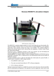
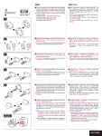
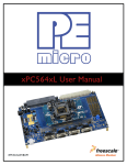
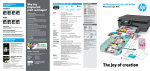
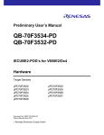
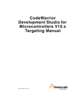
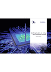
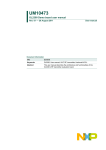
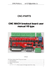
_ V1.4 Adapters “Leopard” Nexus Emulation Adapter 257BGA – 144TQ Ordering code IA257BGA144TQ-564XL Target CPU package: QFP144 Original microcontroller in the QFP144 package has only 4-bit Nexus port. “Leopard” Nexus Emulation Adapter is based on the MPC5643L microcontroller in the BGA257 package (emulation device), which exposes 12-bit Nexus port. The Emulation Adapter exhibits the same behaviour to the target as the original 144-pin microcontroller and additionally provides a 12-bit Nexus port (max. port bandwidth), which allows advanced functionalities like trace, profiler and code coverage. A 144-pin solder part, which must be ordered separately under the IA144TQ-SOLDER ordering code, is soldered to the target (PCB) instead of populating the original microcontroller in a 144-pin QFP package. Then the Emulation Adapter, which acts as the original microcontroller and additionally provides debug Nexus port, is connected on top. Contact iSYSTEM sales representative for more details on available Nexus tools. iSYSTEM, November 2013 1/8 • IA144TQ-SOLDER Solder part, which is soldered down to the target. (Unit: mm) A B 22 1.125 C 23.0 D 23.0 E 2.15 K 25.05 L 25.05 Recommended (by TET) PCB footprint size IA144TQ-SOLDER dimensions iSYSTEM, November 2013 2/8 Jumper configuration J1 and J2: clock source configuration Jumpers J1 and J2 select clock source for the emulation device. Per default, both jumpers are set to position 1-2, which yields clock source being used from the emulation adapter. For the first time after receiving the emulation adapter, it is recommended that it’s tested with this setting. Once it’s confirmed that it is operational, target clock use (J1 & J2 position 2-3) can be tested. Note that the emulation adapter may not operate when crystal circuit is used in the target. Typical design guideline is that a crystal should be as close as possible to the microcontroller. However, it may happen that the target crystal may not oscillate with the emulation adapter since clock lines (XTAL, EXTAL) between the target and the emulation device on the emulation adapter are prolonged. There should be no problem with the oscillator being used in the target. If an oscillator in the target is not an option and the target crystal doesn’t oscillate in conjunction with the emulation adapter, clock from the emulation adapter must be used (J1 & J2 position 1-2). In this case, a crystal circuit must be assembled on the emulation adapter. Crystal circuit Crystal circuit is located in the corner of the emulation adapter, next to the Nexus (Mictor) connector. Per default 10pF capacitors are populated for C3 and C4 and 40MHz crystal for Q1. Note that these values are valid for 40MHz crystal only. If different crystal is used, appropriate capacitors must be soldered (replace original ones). Note: It has been confirmed that some quartz crystals don’t generate sufficient clock amplitude for the MPC564xL microcontroller operation. Freescale MPC564xL reference design uses the NX5032GA quartz and no problems have been noticed with the emulation adapter when using this particular type. iSYSTEM, November 2013 3/8 J3: target reset configuration Jumper J3 connects the reset line between the emulation device and the target. By default J3 is not populated. U3: power selection The U3 header row is used for power supply selection. Power supplies are organized in groups and the same voltage must be supplied for each group. Refer to the microcontroller user manual for more details which power supply designation belongs to which power supply. Signal direction Signal Pin Pin Signal Signal direction IEA-PS jumper NC 1 2 NC Target VDD_HV_REG 3 4 CVDD_HV_REG CPU J1 Target VDD_HV_PMU 5 6 CVDD_HV_PMU CPU J2 Target VDD_HV_FLA 7 8 CVDD_HV_FLA CPU J3 Target VDD_HV_ADV 9 10 CVDD_HV_ADV CPU J4 Target VDD_HV_ADR1 11 12 CVDD_HV_ADR1 CPU J5 Target VDD_HV_ADR0 13 14 CVDD_HV_ADR0 CPU J6 Target VDD_HV_OSC 15 16 CVDD_HV_OSC CPU J7 Target VDD_HV_IO 17 18 CVDD_HV_IO CPU J8 NC 19 20 NC GND 21 22 GND GND 23 24 GND GND 25 26 GND J0 J9 U3 signal description By default all jumpers are set even though only some jumpers affect the configuration. When jumpers are set, target power supply coming from the target gets connected to the microcontroller residing on the emulation adapter. If a different power source is to be used (e.g. in case of a standalone operation), jumpers must be removed and power source must be applied to CVDD_HV_REG (pin4), CVDD_HV_PMU (pin6), CVDD_HV_FLA (pin8), CVDD_HV_ADV (pin10), CVDD_HV_ADR1 (pin12), CVDD_HV_ADR0 (pin14), CVDD_HV_OSC (pin16), CVDD_HV_IO (pin18), and GND (pins 21-26) signals. iSYSTEM, November 2013 4/8 iSYSTEM power supply adapter can be ordered separately under the IEA-PS ordering code. It connects on top of the emulation adapter directly to the U3 header row and allows standalone usage of the emulation adapter. 3.3V or 5V voltage can be selected for each group with appropriate jumpers J0-J9. This is convenient when the target is not available or it’s not adjusted for the emulation adapter connection yet. IEA-PS (optional emulation adapter power supply) iSYSTEM, November 2013 5/8 Schematic iSYSTEM, November 2013 6/8 iSYSTEM, November 2013 7/8 Disclaimer: iSYSTEM assumes no responsibility for any errors which may appear in this document, reserves the right to change devices or specifications detailed herein at any time without notice, and does not make any commitment to update the information herein. iSYSTEM. All rights reserved. iSYSTEM, November 2013 8/8