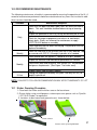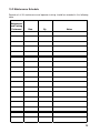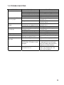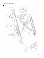
1
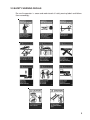
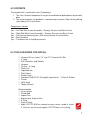
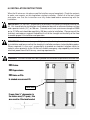
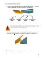
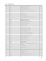
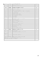
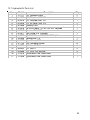
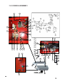
INSTALLATION and OPERATION MANUAL
10K
10KSCISSOR
SCISSORLIFT
LIFT
MODEL:
MODEL:EELR3__A
EELR3__A(58/59/60/61)
(58/59/60/61)
READ THIS INSTRUCTION MANUAL THOROUGHLY BEFORE
INSTALLING, OPERATING, SERVICING OR MAINTAINING
THE LIFT.
SAVE THIS MANUAL.
Snap-On Tools Corporation
1-800-268-7959
MAR 2008 REV.- 6-3635
Table of Contents
1.0 SAFETY INSTRUCTIONS ......................................................................... 3
2.0 SAFETY WARNING DECALS ................................................................... 5
3.0 SPECIFICATIONS ..................................................................................... 6
4.0 CONTENTS ............................................................................................... 7
5.0 TOOLS REQUIRED FOR INSTALL ........................................................... 7
6.0 INSTALLATION INSTRUCTIONS .............................................................. 8
6.1 Bay Layout ......................................................................................... 9
6.2 Unpacking the Lift ........................................................................... 12
6.3 Electrical Connection ..................................................................... 13
6.4 Hydraulic Connections ................................................................... 14
6.5 Air Safety and Auxiliary Air Connection ........................................ 15
6.6 Bleeding Procedure ........................................................................ 16
6.7 Level and Support ........................................................................... 17
6.8 Anchoring Procedure...................................................................... 18
6.9 Grouting Procedure (Optional) ...................................................... 20
7.0 ACCESSORY INSTALLATION ................................................................ 21
8.0 FINAL PROCEDURES ............................................................................ 24
8.1 Check of Assembled Lift ................................................................ 24
8.2 Operation Test With Vehicle ........................................................... 25
9.0 LIFT OPERATION .................................................................................... 26
9.1 Raising the Lift ................................................................................ 26
9.2 Lowering the Lift ............................................................................. 26
10.0 RECOMMENDED MAINTENANCE ....................................................... 27
10.1 Kicker Greasing Procedure........................................................27
10.2 Maintenance Schedule ................................................................. 28
11.0 TROUBLE SHOOTING .......................................................................... 29
12.0 LIFT ASSEMBLY ................................................................................... 30
12.1 Lift Parts List ................................................................................. 31
13.0 HYDRAULIC/AIR PARTS ASSEMBLY .................................................. 33
13.1 Hydraulic/Air Parts List ................................................................ 34
14.0 CONSOLE ASSEMBLY ......................................................................... 35
14.1 Console Parts List ........................................................................ 36
15.0 POWER PACK ASSEMBLY .................................................................. 38
15.1 Power Pack Parts List .................................................................. 39
16.0 AVAILABLE ACCESSORIES ................................................................. 40
2
1.0 SAFETY INSTRUCTIONS
When using this lift, basic safety precautions should always be followed, including the following:
1 Read all instructions and safety information in this manual and on the lift thoroughly
before installing, operating, servicing, or maintaining the lift.
2 Inspect the lift DAILY. Do not operate if it malfunctions or problems have been
encountered.
3 Never attempt to overload the lift. The manufacturer’s rated capacity is shown on the
identification label on side of the deck. Do not override the operating controls or safety
devices.
4 Only trained and authorized personnel should operate the lift. Do not allow customers
or bystanders to operate the lift or be in the lift area.
5 CAUTION! Never work under the lift unless mechanical safety locks are engaged.
6 Always keep the lift area free of obstruction and debris. Grease and oil spills should
always be cleaned up immediately.
7 Never raise a vehicle with passengers inside.
8 Always chock vehicle wheels before raising or lowering the lift.
9 Before lowering check the area for any obstructions including people.
10 To protect against risk of fire, do not operate the lift in the vicinity of open containers of
flammable liquids.
11 Adequate ventilation should be provided when working on internal combustion
engines.
12 Never open hydraulic lines under pressure.
READ AND SAVE THESE INSTRUCTIONS
3
Installation shall be performed in accordance with ANSO/ALI ALIS, Safety Requirements for
Installation and Service of Automotive Lifts.
For additional safety instructions regarding lifting, lift types, warning labels, preparing to lift,
vehicle spotting, vehicle lifting, maintaining load stability, emergency procedures, vehicle
lowering, lift limitations, lift maintenance, good shop practices, installation, operator training
and owner/employer responsibilities, please refer to “Lifting It Right” (ALI/SM) and “Safety
Tips” (ALI/ST).
For additional instruction on general requirements for lift operation, please refer to “Automotive
Lift-Safety Requirements For Operation, Inspection and Maintenance” (ANSI/ALI ALOIM).
ATTENTION! THIS LIFT IS INTENDED FOR INDOOR INSTALLATION ONLY. IT
IS PROHIBITED TO INSTALL THIS PRODUCT OUTDOORS. FAILURE TO
ADHERE WILL RESULT IN LOSS OF WARRANTY AND POSSIBLE DAMAGE
TO THE EQUIPMENT.
4
2.0 SAFETY WARNING DECALS
Be sure the operator is aware and understands all safety warning labels and follows
them accordingly.
5
3.0 SPECIFICATIONS
M ax im um Capac ity :
Overall W idth (min-max ):
Overall Length:
M ax im um Rais ed Height:
M inim um Lowered Height:
Runway W idth
Lifting Tim e:
P ower Requirem ents :
A ir Supply requirem ents :
Hy draulic Oil Capac ity:
Oil Ty pe:
10 000 lbs
4 536 k g
92-1/2 - 94-1/2 Inc hes
2350-2400 m m
265-3/8 Inc hes(m ax)
6741m m
255-3/8 Inc hes (m in)
6486m m
73-3/8 Inc hes
1861 m m
9 Inc hes
229 mm
26 Inches
660 mm
85 s econds at max . c apac ity
220V , 1 P h, 60 Hz, 25A
90 to 120 ps i
Tank s iz e: 4.0 gal
Lift us es: 3.0 gal
ISO 32 (10 weight) hy draulic oil
Figure 1 Lift Dimensions
6
4.0 CONTENTS
The complete lift is contained in two (2) packages:
1. The main structural components are pre-assembled and packaged on top of each
other.
2. The remaining parts are packed in a console/accessory box. Refer to the packing
slip inside for a list of contents.
Components include:
1pc. – Left Side Main Frame Assembly: Runway, Scissors and Base Frame
1pc. – Right Side Main Frame Assembly: Runway, Scissors and Base Frame
1pc. – Console and accessory box. (See accessory box list for contents)
1pc – Grout container
1pc. – Customer care kit including manuals
5.0 TOOLS REQUIRED FOR INSTALL
Hammer Drill or similar, 1/4” and 1/2” Concrete Drill Bits
4’ Level
SAE Wrenches and Sockets
Hammer
Pry Bar – 5’ Long
Chalk Line
Tape Measure
Side Cutters
Screw Drivers
Hydraulic Fluid ISO 32 (10 weight hydraulic oil) - 15 liters/4 Gallons
Funnel
Utility Knife
Torque Wrench
Recommended:
Laser Leveler
Plumb Bob
Impact Gun
Boom and/or Engine Hoist
8’ Sling
Engine Crane
Apply LOCTITE #242 on required fasteners where symbol is shown.
If fasteners are removed reapply LOCTITE before re-installing.
7
6.0 INSTALLATION INSTRUCTIONS
When the lift arrives on site, please read the Installers manual completely. Check the contents
to make sure no parts are missing before starting installation. Gather all of the tools listed
and make sure that the instructions are fully understood before commencing with the
installation.
IMPORTANT: It is the user’s responsibility to provide a satisfactory installation area for the
lift. Lifts should only be installed on a level concrete floor with a minimum thickness of four
and a quarter inches (4¼”) or 108 mm. Concrete must have a minimum strength of 3000
psi or 21 MPa and should be aged thirty (30) days prior to installation. Please consult the
architect, contractor or engineer if doubt exists as to the strength and feasibility of the floor
to enable proper lift installation and operation.
IMPORTANT: It is the user’s responsibility to provide all wiring for electrical hook-up prior
to installation and to ensure that the electrical installation conforms to local building codes.
Where required, it is the user’s responsibility to provide an electrical isolation switch located in close proximity to the lift that will enable emergency stop capability and isolate
electrical power from the lift for any servicing requirements.
WARNING: The floor surface must be inspected and the below requirements must be met.
NO Drains.
NO Depressions.
NO Holes or Pits.
In shaded area around lift.
Kicker Area
If more than ¼” depression in
the kicker area (10” span) , this
area must be filled and leveled.
8
6.1 Bay Layout
Note: Leave any additional
room for any desired aisle or
work area. Recommended
clearance around the lift is
three (3) feet. Ensure
clearance conforms to local
building and fire codes.
Recommended overhead
clearance is a minimum
twelve (12) foot ceiling
providing 6 feet for the
maximum lift height and 6 feet
for the supported vehicle. For
vehicles taller than 6 feet it is
recommended that the user
provides additional overhead
clearance or a shut off
mechanism to stop the lift
from raising the vehicle too
high.
Figure 2 - Typical Bay Layout (Flush Mount)
9
Note: Leave any additional room for
any desired aisle or work area.
Recommended clearance around the
lift is three (3) feet. Ensure clearance
conforms to local building and fire
codes.
Recommended overhead clearance
is a minimum twelve (12) foot ceiling
providing 6 feet for the maximum lift
height and 6 feet for the supported
vehicle. For vehicles taller than 6 feet
it is recommended that the user
provides additional overhead
clearance or a shut off mechanism
to stop the lift from raising the vehicle
too high.
Figure 3 - Typical Bay Layout (Surface Mount)
10
SEE FIG 3 FOR RUNWAY OPENING
Figure 4 : Baseframe Locations
IMPORTANT: DO NOT CUT THE SHIPPING STRAPS HOLDING EACH SCISSOR ASSEMBLY
TOGETHER UNTIL INSTRUCTED TO DO SO.
1. With reference to Figure 3, the installer should locate the most suitable location in the
shop for the lift.
2. Snap a chalk line for the centerline of the lift ensuring that it matches the centerline of
the bay door.
* See Section 6.0 Installation Instructions for the floor surface requirements.
11
3. Measure and snap two (2) parallel chalk lines on either side the centerline for the
inside edges of the baseframes. Refer to Figure 4 for the dimensions necessary to
provide the desired width between the two runways. A distance of 35 ¼” (895mm)
between the baseframes will provide the standard width of 38” between the inside of
the runways.
4. Measure and snap a chalk line parallel to the shop door for the front of the baseframes,
a minimum distance of 249 1/8” (6328mm) is recommended.
5. Before proceeding, ensure that once the runways are installed adequate workspace
will remain in front of the lift.
Refer to the minimum requirements listed in the installation and operation
manual of any alignment equipment as needed.
6.2 Unpacking the Lift
1. Unpack the console and place it in the desired location at the rear of the lift. The
console can be placed on either the left or right hand side of the lift. The console
must be located so the operator is always facing the lift.
2. Unpack the runways and lay each baseframe along the chalk lines.
Do not remove the individual strapping on the runways until they
have been positioned on the chalk lines.
3. Position the baseframes on chalk lines, and ensure that the runways are parallel.
Before complete positioning of the last scissor be sure to remove the shipping tubes.
Ensure that both the inside dimensions (front and back) of the baseframes as well
as the diagonal distances are equal.
4. Remove the remaining packing straps, and remove the
hydraulic hoses and polytubes from under the runway. Hoses
are located under the rear portion of the runway and are
factory pre-installed
Note: do not pull excessively on the hoses as it may
Center Line
strain the connections to the baseframe.
Jackbeam Rail
Rear
Turnplate
Front
Chalk Line
Ensure that the turnplate pockets are at the front, and that Jack Beam
rails for each runway face each other.
Ensure there are no holes, depressions, or drains inside the installation area.
See Section 6.0 for requirements.
12
6.3 Electrical Connection
DANGER! ENSURE THAT ELECTRICAL CONNECTIONS ARE COMPLETED BY A LICENSED
ELECTRICIAN! ELECTRICAL SHOCKS CAN CAUSE SERIOUS INJURY OR EVEN DEATH.
NOTE: Overload fuse does not come with single phase power unit
Figure 5 - Electrical Connections
13
6.4 Hydraulic Connections
1. Open the rear access covers of the console.
2. Unravel all hoses and air lines from each runway and connect the hydraulic lines as
shown in Figure 6.
Always make sure that the connections are clean to avoid contaminating
the hydraulic system.
Do not kink hydraulic hoses or air lines.
Do not remove hydraulic fittings while under pressure..
3. Connect the cylinder hoses (2-2177) to the pump manifold.
Figure 6 - Air Safety, Auxiliary Air and Hydraulic Connections
14
6.5 Air Safety and Auxiliary Air Connection
WARNING! WEAR SAFETY GOGGLES AND PRACTICE CAUTION WHILE
WORKING WITH COMPRESSED AIR.
1. The ¼” polytube in the control console is already connected to the manual pushbutton
release valve. The polytube should be uncoiled, cut to size and connected to the “T”
inside the console.
2. The 3/8” polytube for the auxiliary air connections is coiled under the right side runway.
Route this hose to the console and connect it to the union inside the console where
the shop air is connected.
3. Connect the compressed air line from the shop to the ¼” NPT port on the back of the
console.
A regulator (supplied by customer) set at 90-120 psi should be used to control the
supply of air to the lift.
An air line filter and water separator should be installed on the air supply (supplied by
customer). *Failure to ensure a clean air supply can result in the premature wear of
air cylinders and valves.
4. Press up button to raise lift off mechanical safety locks.
While holding the air safety release button, press the
down button and lower the lift completely to the ground.
5. Check the air system for any leaks.
Up Button
Down Button
Air Safety Release Button
15
6.6 Bleeding Procedure
Top Cover
1. Once the main electrical power supply has been connected
remove console top cover.
2. Using a funnel with a screen filter, add 15 litres/ 4 gallons
hydraulic fluid ISO 32 to the power pack reservoir.
(10 Weight Hydraulic Oil).
3. Turn the potentiometer adjustment fully clockwise. Do
not use excessive force to turn screw. The
potentiometer adjustment is located on the PCB board.
4. Press the up control button until the LED illuminates.
(Approximately 12”-14” high)
5. Press the Safety Release Button and the Down Button to
lower the lift to the ground and hold until the LED light goes
off. This will release air from the hydraulic system. +
Note: If the LED is not illuminated the lift will not lower
– press the up button and raise the lift until the LED
comes on. Once the LED is illuminated, the lift can be
lowered.
Potentiometer
LED
6. Repeat these steps 5-6 times to completely bleed the system of air.
Check the lift for hydraulic leaks at all connections. When complete,
turn the potentiometer adjustment fully counter clockwise.
LED
Potentiometer
7. After bleeding, it is recommended that the fitting
assemblies located on the flow divider valve, where
hydraulic hoses from lift attached be cleaned.
Note: Place the fitting on a workbench and use an
air gun to blow through the filter in the opposite
direction to flow from the lift.
Filter Assembly
8. Reinstall fitting assemblies and connect hydraulic
hoses.
16
6.7 Level and Support
NOTICE
CORRECT LEVELING IS IMPORTANT TO ENSURE THE PROPER OPERATION OF
THE LIFT. TAKE PRECAUTIONS TO ENSURE ACCURATE LEVEL READINGS WHEN
PERFORMING THIS PROCEDURE.
Side-to-side leveling measurements should be taken off the baseframe, and measurements should be taken on each baseframe as well as between the two baseframes. Frontto-back level measurements should be taken on the runways.
1. Press the up button
and raise the lift to the fully extended
operating position. Check the location of the baseframes
compared to Figure 4, and make minor adjustments as required.
2. Level the baseframes using the 5/8” leveling bolts provided at
each of the four (4) corners.
Leveling Bolt 5/8”-UNC Hex Bolt (6-1670)
¾”-16 UNF Support Bolt
3. Use shims provided to support under glide block area,
kicker area of baseframe and under front hinges. See Figure 7.
See section 6.0 Installation Instructions for floor requirements.
Figure 7 - Shimming
17
4. Verify that the baseframes are level side-to-side and that the runways are level
front-to-back. The front turnplate and rear slip plate are the areas of interest. Check
that the spacing between the runways is as desired, and that this spacing is equal at
both the front and rear of the lift. Runway
Baseframe
*Check that the diagonal measurements between opposite corners of the baseframes
are equal. Lower and raise the lift and repeat these measurements.
5. Once lift is level, back off 5/8” leveling bolts so
that the base is firmly sitting on the shims. Recheck to make sure the lift is still level and shims
are holding properly.
Note: These bolts must be removed once the
shims are installed under the base correctly.
Leveling
Bolt
Locations
6.8 Anchoring Procedure
Figure 8 - Anchoring
18
1. Lower the lift and measure the distance between the
Jackbeam rails at front and rear of the lift.
2. Raise the lift to full height and repeat the
measurements, and ensure there are no differences.
3. Using a hammer drill and a ½” concrete bit, drill
through the floor at each of the six (6) anchor bolt
locations on each of the base frames. Make sure that
the 1/2” concrete drill bit is in good condition. Refer to
baseframe figure to the right.
4. Assemble the nuts and washers on the 1/2” x 4 ½”
long wedge anchor bolts supplied ensuring a minimum
of six threads are visible below the nut, and hammer
in the anchors leaving space for shimming.
J a c k b e a m R a ils
½” x 4 ½” Long
Wedge Anchor bolts
5. Use shims provided to support around anchor position
and hammer anchors until they make contact with the
baseplate.
6. Torque all anchor bolts to 40 ft- lbs (54 N.m).
NOTE: The ½” × 4 ½” long wedge anchor bolts
supplied must have a maximum of 2 ¼” exposed
above the concrete.
NOTE: The wedge anchor must be a minimum of 6 1/8”
away from any cracks, edges and joints
7. Position the console in the final desired location.
Refer to Figure 3. Using a hammer drill and a 1/4”
concrete bit, drill and anchor the console to the
floor using the Nail in Anchors located in the
hardware kit.
Place and Anchor
Console
8. Check that the 3/4" support bolts on the four (4) corners of the baseframes are
adjusted to ensure that the runway is level at fully collapsed position. (9 inches).
9”
Deck
Support Bolt ¾”-16 UNF (6-3194)
Baseframe
9. Clean kicker area and grease kicker using a multipurpose, extreme pressure grease
such as Dynalife L-EP, NLGI Grade 2 or equivalent. Refer to Maintanence Section
19
10.1 for procedure.
6.9 Grouting Procedure (Optional)
1. Pour grouting under the load area of each base frame as shown in Figure 9. Ensure that grout is evenly distributed under the frame and finish the edges with a 45
degree chamfer. Refer to specific grouting instructions on the package. Leave a
drain area to allow any liquids to escape.
2. GROUTING MUST FULLY CURE BEFORE PROCEEDING. Do not operate the lift
while grout is curing. Refer to instructions on the package for recommended cure
times. [Non-Shrink Grout (3000psi min. in 24hrs, 7000psi min. in 30 days)]
Figure 9 - Grouting Locations
20
7.0 ACCESSORY INSTALLATION
1. Install the front Wheelstops located in the accessory box using the ½” Hex Bolts,
Washers, Lockwashers, and Hex Nuts located in the hardware kit.
The runway stops are designed as a secondary means to restrain a vehicle
from inadvertently rolling off the runways. Property damage and physical injuries
may occur if this warning is not adhered to.
2. Install the rear approach ramps using the Approach Ramp Pins located in the accessory box, and the Flatwashers and Cotter Pins located in the hardware kit.
3. Install Jackbeams with reference to the Jackbeam user manual.
21
4. Position the moveable workstep in the desired location. There are slots along the
span of each runway where the workstep can be mounted. When not in use, the
workstep can be stored under the front section of the runway.
WARNING!
ENSURE WORKSTEP IS FULLY ENGAGED PRIOR TO USE. IF MORE
THAN ONE WORKSTEP IS IN USE, DO NOT TRY TO STEP ACROSS
OR JUMP FROM ONE STEP TO ANOTHER. NEVER USE THE
WORKSTEP WHILE THE LIFT IS IN OPERATION. SERIOUS INJURY
COULD RESULT FROM IMPROPER USAGE OF THE WORKSTEPS.
WARNING!
WORKSTEP MAXIMUM CAPACITY IS 250 LBS.
WARNING!
FOR FLUSHMOUNT INSTALLATIONS ENSURE WORKSTEP IS RE
MOVED BEFORE RAISING OR LOWERING THE LIFT.
22
5. Install line covers once console is installed and hydraulic lines are routed. Use supplied
1/4” x 1” long nail in anchors (6-0141) to secure line covers. See below for
arrangement.
REAR LINE COVER ELBOW
(1-3510)
REAR LINE COVER TEE
(1-3511)
REAR LINE COVER (QT Y. 2)
(1-3509)
REAR LINE COVER
SPACER (QTY. 3)
(1-3508)
23
8.0 FINAL PROCEDURES
8.1 Check of Assembled Lift
1. Final dimension check after anchoring.
____
2. Check for air and hydraulic leaks.
____
3. Re-check level of decks, front to rear , side to side.
____
4. Check all fasteners, tighten if necessary.
____
5. Operate lift to full stroke then lower to ground while checking
for proper functionality.
____
6. Ensure Customer Care Kit is complete and given to operator.
____
a. Operation Manual
____
b. ANSI / ALI Lift It Right Manual
____
c. ANSI / ALI Safety Tip Card
____
d. ANSI / ALI ALIS Safety Requirements for Installation
and Service of Automotive Lifts
____
e. ANSI / ALI Quick Reference Guide
____
7. Train end user on operation of lift.
____
24
8.2 Operation Test With Vehicle
1. Lower lift to the ground. (Make sure Green Light is OFF)
____
2. Drive vehicle on to lift.
____
3. Raise lift to and lower onto 3-4 lock positions during full rise to ensure
all locks are working correctly.
____
4. Check lowering speed and smooth decent rate.
____
5. Lower lift to the ground and drive vehicle off lift.
____
If any problems occur during the final checkout or operation of the lift please contact customer
service at 1-800-225-5786
25
9.0 LIFT OPERATION
9.1 Raising the Lift
1. If the lift is equipped with sliding Jack Beam(s), be sure that the Beam(s) are positioned at the front or mid travel of the lift, fully down, and with the risers removed and
stored. Never store Jack Beams at the rear of the lift.
2. Ensure that the lift is fully lowered before attempting to load or unload a vehicle.
3. Ensure that locking pins are in the front turnplates and rear slip plates before driving a
vehicle onto the lift.
4. Position the vehicle on the lift ensuring the resulting load on the deck is distributed as
evenly as possible. Under no circumstances should a vehicle be lifted if the weight
distribution is unbalanced by more than 10% on either side.
NOTE: THE VEHICLE IS POSITIONED CORRECTLY WHEN THE DISTANCE FROM
THE CENTER OF THE TIRES TO THE INSIDE EDGE OF THE RUNWAYS IS EQUAL
ON BOTH RUNWAYS, FOR BOTH THE FRONT AND REAR TIRES.
6. Chock the vehicle using the wheel chocks provided.
7. Check that there are no obstructions above the lift that could damage the lift or vehicles.
8. Raise the lift by pressing the up button on the control console. Raise the lift until the
green light is illuminated. (The lift can only be lowered if the green light is on).
9. Lower the lift onto a mechanical safety lock by pressing the down button. Continue to
hold the down button until the green light goes off. (Approx. 3-10 sec).
WARNING: NEVER WORK UNDER A VEHICLE OR THE LIFT UNLESS IT IS POSITIONED
ON BOTH MECHANICAL SAFETIES!
9.2 Lowering the Lift
NOTE: The lift can only be lowered if the green light is on. If the light is not on, raise the lift
until the light turns on. If the lift is at its maximum lifting height, a change in tone
may be noticed while raising the lift (This change is the pump working at max relief
pressure). Only press the up button until the green light comes on.
1. Lower the vehicle from the Jack beams and remove lift pads and store. If removing the
vehicle from the lift, slide Jack Beams to their appropriate position, at the front or mid
section of the lift. Check that there are no other obstructions under the lift or vehicle.
2. Raise the lift by pressing the up button until both runways are clear of their mechanical
safety locks.
3. Press the air safety release button to release the mechanical safeties.
4. While holding the air safety release button, press the down button and lower the lift to
the completely collapsed position.
5. Remove wheel chocks and ensure that locking pins are in the front turnplates and rear
slip plates before driving a vehicle off the lift.
6. Be certain that the lift is completely lowered before removing the vehicle from the lift.
ATTENTION: THE OPERATOR MUST ALWAYS KEEP THEIR ATTENTION ON THE OPERATION OF THE LIFT WHILE RAISING OR LOWERING. IF AN OBSTRUCTION IS SEEN,
RELEASE BOTH THE AIR SAFETY RELEASE BUTTON AND THE DOWN BUTTON TO
STOP THE LIFT.
26
10.0 RECOMMENDED MAINTENANCE
The following maintenance schedule is recommended for ensuring the operation of the lift. A
record of maintenance performed should be maintained and any items that resulted in additional service should be noted.
Schedule
Maintenance Required
Check that the upper and lower glide tracks are clean and free of
debris. This area should be checked before raising or lowering
the lift.
Inspect the operation of the lift by raising and lowering the lift fully.
Daily
Check for the proper engagement and release of mechanical
safety locks. If bolts are removed for maintenance re-apply
LOCTITE #242 before re-assembly
Check hydraulic lines for leaks and fraying. Frayed hoses must be
replaced immediately.
Weekly
Check the fluid level in the reservoir with the lift fully lowered. Top
up reservoir with ISO 32 (10 weight) hydraulic oil as needed.
Check anchor bolts for tightness. Torque to 40 ft-lbs if needed.
Inspect the electrical and mechanical operation of all switches.
Monthly
5 Year
Clean kicker plate and re-grease. See Section 10.1 for procedure
and grease requirements. (See Figure 7 for kicker area).
Inspect runway stop fasteners monthly.
Change the hydraulic fluid every five years. Use only ISO 32 (10
weight) hydraulic oil.
NOTE: FAILURE TO FOLLOW RECOMMENDATION MAY AFFECT WARRANTY OF LIFT
10.1 Kicker Greasing Procedure
1. Clean both the kicker and the kicker area on the baseframe.
2. Grease kicker using a multipurpose, extreme pressure grease such as Dynalife
L-EP, NLGI Grade 2 or equivalent.
3. Locations to be cleaned and greased are as shown below:
Clean surfaces
Grease across span of glide block
27
10.2 Maintenance Schedule
Records of all lift maintenance and operator training should be recorded in the following
table.
Maintenance
and Training
Performed
Date
By
Notes
28
11.0 TROUBLE SHOOTING
P ROB LE M
M o to r d o e s no t run.
M o to r runs b ut lift
d o e sn't g o up .
L ift d o e sn't co m e
down.
S a fe ty d o e sn't
d ise ng a g e .
L ift g o e s up unle ve l.
A nc ho r B o lts d o no t
sta y tig ht
N o ise
RE A S ON
B a d fuse o r c ircuit b re a ke r.
Inco rre ct vo lta g e to m o to r.
Inco rre ct w iring .
M o to r s w itch is m a lfunc tio ning
M o to r b urne d o ut
L o w o il le ve l
S O L U TIO N
R e p la ce fuse o r re s e t b re a ke r.
P ro vid e p ro p e r vo lta g e to m o to r.
H a ve ce rtifie d e le ctricia n che ck
R e p la ce m o to r sw itch.
R e p la ce m o to r.
F ill re se rvo ir w ith p ro p e r
hyd ra ulic o il.
W ro ng ro ta tio n
C he ck fo r o il flo w & re ve rse
e le ctrica l le a d s
D irt in hyd ra ulic line s
*S e c ure ve hicle o n lift, a nd cle a n
C he ck p o w e r to hyd ra ulic line s hyd ra ulic line s.
C he ck p o w e r to so le no id s
N o p o w e r to so le no id s
L ift no t ra ise d hig h e no ug h fo r P re ss U p b utto n fo r lo ng e r
p e rio d o f tim e .
d ise ng a g e m e nt
A ir no t sup p lie d to a ir cylind e r C he ck if sup p ly line ha s a ir.
A ir cylind e r m a lfunctio ning
R e p la ce a ir c ylind e r.
F lo w d ivid e r d e fe ctive
R e ve rse hyd ra ulic c o nne ctio ns
R e m o ve & insp e ct flo w thro ug h
B lo c ka g e in hyd ra ulic ho se
line
H o le s a re to la rg e .
R e lo ca te lift using p ro p e r d rill
size .
Inco rre ct co ncre te flo o r
C o ncre te sho uld b e re p la c e d b y
sp e c ifica tio n. (Thickne ss a nd
a n a p p ro p ria te co ncre te p a d .
S tre ng th)
(C o nsult P ro d uct M a nufa c ture r /
S up p lie r fo r furthe r d e ta ils)
S q ue e king no ise d uring firs t
C le a n kicke r a nd a re a . G re a se
fe w inche s o f rise
kic ke r (s e e S e ctio n 1 0 .1 fo r
G re a sing P ro ce d ure )
29
12.0 LIFT ASSEMBLY
30
12.1 Lift Parts List
Item#
1
2
3
4
5
6
7
8
9
10
11
12
13
14
15
16
17
18
19
20
21
22
23
24
25
26
27
28
29
30
31
32
33
34
35
36
37
38
39
40
41
42
Part #
3-0978
2-2301
4-1152
6-2899
6-3087
6-3419
1-2795
1-2791
6-0233
2-2470
6-3419
6-0816
1-3224
1-3223
6-1523
1-3185
1-0757
1-3171
6-3418
4-1181
4-1191
4-1227
4-1228
1-3171
1-3047
2-2111
2-2112
2-2183
1-3186
4-1171
1-2792
2-2117
1-3159
3-0905
3-0698
1-1099
1-3062
6-0267
2-2505
2-1733
6-0233
6-2281
1-2788
6-0340
6-3468
80259000
Description
BASEFRAME WELDMENT
BASE FRAME COVER (L)
WELDMENT, SCISSOR
BUSHING, PIVOT, 1-1/2" ID, 24TH24
BUSHING 1-1/4"
1-5/8 SELF-LUBRICATING BUSHING, 26TH24
SCISSOR SPACER
SCISSOR PIN
SNAP RING, #5100-150
KICKER ASSEMBLY
1-5/8 SELF-LUBRICATING BUSHING, 26TH24
Flat Washer, #10
BEARING BLOCK, OUTER
BEARING BLOCK, INNER
SCREW, #10 X 1-1/2, SELF-TAP
KICKER PIVOT PIN
NYLON THRUST WASHER
THRUST WASHER
SNAP RING, #5100-163
DECK WELDMENT, LH (173")
DECK WELDMENT, RH (173")
DECK WELDMENT, LH (155")
DECK WELDMENT, RH (155")
THRUST WASHER
INNER SLIDER BLOCK ASSEMBLY
SAFETY BAR BOTTOM (LASER CUT)
SAFETY BAR, TOP (LASER CUT)
SCISSOR SAFETY COVER
KICKER CLEVIS PIN
CYLINDER ASSEMBLY
SLIDER BLOCK
WHEELSTOP WELDMENT
ADAPTOR PLATE
APPROACH RAMP ASSEMBLY (SURFACE MOUNT)
APPROACH RAMP ASSEMBLY (FLUSH MOUNT)
CLEVIS PIN
RAMP ROLLER
Cotter Pin, 1/8" Dia. x 1" LG.
REAR SLIP PLATE
ROD END
SNAP RING, #5100-150
PHILIPS SCREW #6
HINGE PIN
CIRCLIP TRU-ARC #5100-125
HEX HEAD GR5 BOLT, 3/4-16 UNF X 1 3/4 LG
HEX JAM NUT, 3/4"-NF
Qty.
1
2
1
2
2
2
2
2
4
1
2
5
2
1
5
1
4
8
2
1
1
1
1
4
4
2
2
1
1
1
4
1
1
1
1
2
2
2
1
1
2
4
2
4
4
4
31
43
44
45
46
47
48
49
50
51
52
53
54
55
57
58
59
60
61
62
63
64
65
66
67
68
69
70
71
1-2793
6-0058
6-0067
6-0291
6-0063
6-0059
6-0035
6-3008
6-2940
1-3033
1-3032
3-0812
1-2789
2-2119
6-0666
6-0034
6-0259
6-2936
6-0426
6-0206
2-0637
6-1670
1-1887
6-0738
6-0978
6-0044
2-2409
6-1134
CYLINDER RETAINER
LOCK WASHER, 3/8"
HEX BOLT, 3/8" NC X 1" LG
Hex Bolt,1/2"-13UNC X 1 1/2 LG.
Flat Washer, 1/2"
Lock Washer, 1/2"
NUT, 1/2-13 UNC, HEX
90 HYD ELBOW FORGD 3/8 NPT - 3/8 JIC (FUSE)
BALL BEARINGS
SLIDER PLATE
SLIDER PLATE INSERT
AIR CYLINDER ASSEMBLY
CYLINDER PIN
WORKSTEP
HEX BOLT 3/8 UNC X 1-1/4 LG, GR8
HEX NUT, 3/8" NC
LOCK WASHER, 3/4
HHCS, 3/4-16 UNF X 1-1/2 LG
FLAT WASHER
Shoulder Bolt, 3/8" DIA. X 1" LG.
LOCKING PIN ASSEMBLY
HEX BOLT, 5/8"-NC x 2" LG
HEADED PIN
FLAT WASHER 3/4" SAE
Cotter Pin, 1/8" DIA. X 1 ½" LG.
Hex HD Bolt, 1/2" x 1/2"
WEAR PLATE
SELF TAPPING SCREW, #12 X 1/2" LG
2
12
4
5
5
5
5
1
26
2
10
1
1
1
8
8
2
2
4
4
2
5
2
2
2
2
1
2
OPTIONS
56
4-1101
TURNPLATE ASSEMBLY
1
* NOTE: QUANTITIES LISTED ARE ONLY FOR SINGLE SIDE.
(LEFT ASS'Y 4-1192) (RIGHT SIDE ASS'Y 4-1193).
OPPOSITE SIDES ARE SYMMETRICAL
32
13.0 HYDRAULIC/AIR PARTS ASSEMBLY
33
13.1 Hydraulic/Air Parts List
Item
1
2
3
4
5
6
7
8
9
10
11
12
13
14
15
16
17
Part #
2-2177
6-3009
6-3019
6-3020
6-2956
6-3010
6-0167
6-3011
6-0709
6-0056
6-0170
6-1134
6-0008
6-0032
6-0060
2-2519
2-2520
Description
3/8" Hydraulic Hose
3/8" Polytube, 215" LG
3/8" Polytube, 480" LG
1/4" Air Hose, 350" LG
Velocity Fuse
90 DEG Elbow, 1/4" NPT-M, 3/8" Polytube
Terminal Bolt, 3/4"
Tee Fitting, 3/8" Polytube
90 DEG Elbow, 1/8" NPT, 1/4" Polytube
Lockwasher, 1/4"
Pipe Clamp, 3/8"
Self Threading Screw
1/4" Hex HD Bolt
1/4" Nut PL
1/4" SAE, Flat Washer
Baseframe, Line Cover Rear
Baseframe, Line Cover Front
Qty
2
1
1
2
1
1
1
1
1
7
8
8
4
4
4
1
1
34
32
1
52
51
50
2
5
19
45
44
21
33
3
46
4
45
43
37
35
36
34
44
41
31
30
46
42
10
39
9
11
12
13
18
20
Refer to Power Pack
Assembly/Parts List
38
17
49
14
16
47 48
15
40
7
6
8
14.0 CONSOLE ASSEMBLY
35
14.1 Console Parts List
Item
Part #
Description
Qty
1
2
3
4
5
6
7
8
9
10
11
12
13
14
15
16
17
18
19
20
21
22
23
24
25
26
27
28
29
30
31
32
33
34
35
36
37
38
39
40
41
42
43
44
45
46
47
48
49
50
51
52
3-0973
3-0974
2-2511
2-2512
2-2513
6-2125
6-3409
6-0709
6-0014
6-0710
6-3406
6-3266
6-3597
6-3410
6-2126
6-3415
8-0141
6-3720
6-3580
6-2971
6-3665
6-3684
6-2128
6-2129
6-1364
6-2553
6-3684
6-2127
2-2177
6-2922
6-1055
6-1247
6-0090
2-2592
6-0804
6-0011
6-0797
6-0710
6-0713
6-2314
1-3282
6-3421
6-3422
6-0674
6-0294
6-0295
6-3423
6-3424
6-3305
6-0988
6-2481
6-1766
Front Side Panel
Back Electrical Plate Cover
Power Pack Step
Rear Cover
Top Cover
Printed Circuit Board
Multihole, 3 holes x 7 mm 189.637
Elbow, 90 deg.
Tee, 1/4" NPT
Adapter 3/8" x 1/4" Polytube
Contactor Tayco P/N 3100-20
Fuse Holder 2-Pole Open Style
Fuse, 1A 250V
Bushing Heyco P/N 184.175
Transformer
Grounding Bar
1/4" Polytube, 2 ft.
PowerPack Assy. 230V/1PH/60Hz
Green LED pilot lamp
1/4" Polytube Tee Pushlock
Flow Divider c/w Solenoids
Din Connector High Body Small Conduit
Coil S8 24VDC
Cartridge Valve N/C with manual override
Cartridge Valve Equalize VEI DT
Filter fitting 1/2 BSP #6 JIC c/w Bonded Seal
Pressure SW 80 psi
Filter fitting 3/8 BSP #6 JIC c/w Bonded Seal
Hydraulic Hose
Emergency Pushbutton Contact
Air Release Button
Pushbutton
Flow Control
Hydraulic Hose Ass’y
Elbow, 90 deg.
Adapter, 3/8" M NPT x 3/8" M JIC
Adapter 3/8" NPT M x 3/8"
Adapter 3/8" x 3/8" Polytube
Terminal Bolt, 3/4" (Short)
Electrical Knockout Plug
Power Pack mounting spacer
Screw BHCS 5/16"-18 x 1 1/2"
Screw BHCS 5/16"-18 x 2 1/2"
Washer, Lock 5/16" ID
Nut, 5-16" - 18 UNC Hex
Washer, Flat 5/16" SAE
Screw Pan Sq. SEFL 8 x 1/2" Zinc
Screw 10 x 3/4" Zinc
Hold Down Adhesive Mount Base
Decal Set, ALI/WL 200
Decal, Elec 208 - 230, 60 Hz 1PH 20A
Decal, Capacity 10000lb/4550kg
1
1
1
1
1
1
2
1
1
1
1
1
2
1
1
1
1
1
1
1
1
4
4
3
1
1
2
2
2
1
1
2
1
1
1
1
1
1
1
1
4
4
2
6
6
6
15
3
5
1
1
1
36
37
15.0 POWER PACK ASSEMBLY
38
15.1 Power Pack Parts List
Item
1
2
3
4
5
6
7
8
9
10
Part#
6-3442
6-3443
6-3444
6-3445
6-3446
6-3447
6-3448
6-3452
6-3449
6-3450
Description
PUMP 6.7G , 17 G EAR
SUCTIO N PIPE 3/8”
SUCTIO N FILT ER 3/8” FEM ALE 15 L/MIN
RETURN PIPE
PLASTIC T ANK 12L
MO TO R SHAFT CO UPLING PUMP
MANUAL VALVE
START UP VALVE
TANK BRACKET W ITH SCREW S
MO TOR BRACKETS
Qty
1
1
1
1
1
1
1
1
1
1
39
16.0 AVAILABLE ACCESSORIES
5K Jackbeam
• Air/Hydraulic Pump
• 2 Safety locking Positions
• 3" & 6" Adapter
• Adjustable width
5000 lb max capacity each
Contact supplier for availability and part numbers.
Max capacity is for 10,000 Lb Lifts.
40