1
NETWORK CAMERA
Operation Guide
Be sure to read Start Guide and this Operation Guide before using the network camera.
Introduction
Thank you for purchasing Canon Network Camera VB-C60/VB-C60B (hereafter referred to as
"VB-C60".)
The only difference between VB-C60 and VB-C60B is the exterior color.
This Operation Guide describes how to set up and use VB-C60. Read these guides carefully
before using the VB-C60 to ensure that you make the best possible use of this product. Also, be
sure to read the ReadMe file on the Setup CD-ROM.
For the latest information on this product (firmware, bundled software, operation manuals,
operating environment, etc.), visit our website.
Copyright
Videos, images or sounds recorded with your VB-C60 may not be utilized or published,
without consent of copyright holders, if any, except in such a way as permitted for
personal use under the relevant copyright law.
Notes
1. All rights reserved.
2. The contents of this guide are subject to change without any prior notice.
3. This document has been prepared with utmost attention to accuracy. If you have any
comment, however, please contact the Customer Service Center indicated on the back
cover.
4. Canon shall assume no liability for any outcome of using this product, regardless of
Items 2 and 3 above.
ii
Introduction
Notes on privacy and publicity rights regarding the
utilization of video/audio
When using the VB-C60 (for image or audio recording), it is the responsibility of the users
to take all care to protect privacy and avoid any violation of publicity rights. Canon shall
have no liability whatsoever in this regard.
Reference
z Please be sure to gain approval of the building management office before installing a
camera, if copyrighted architectural structures or copyrighted premises are got into
the frame.
Legal Notice
In some countries or regions, monitoring via a camera is banned by the law or regulation,
and the law or regulation depends on the country or region. Before using the VB-C60,
confirm the law or regulation of the country or region where the camera is used.
Trademark Notice
z Canon and the Canon logo are registered trademarks of Canon Inc.
z Microsoft Windows and Microsoft Internet Explorer are trademarks or registered
trademarks of Microsoft Corporation in the United States and other countries.
z Windows is legally recognized as the Microsoft Windows Operating System.
z Other brands or product names in this guide are trademarks or registered trademarks
of their respective companies.
Notes on Use of Bundled Software RM-Lite (Disclaimer)
Malfunction, failure of RM-Lite or other factors may cause problems, such as recording
failure, recorded data corruption or loss. Canon shall have no liability whatsoever for any
loss or damages incurred by the user as a result of such problems.
iii
Introduction
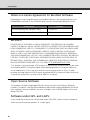
Notes on License Agreement for Bundled Software
Regarding the license agreement for the bundled software, see the following file in the
BundledSoftware folder in the LICENSE folder found in the bundled Setup CD-ROM.
Software type
File name
VB Initial Setting Tool, VBAdmin Tools
VBTools.txt
Network Video Recording Software RM-Lite
RM-Lite.txt
MPEG-4
NOTICE ABOUT THE MPEG-4 VISUAL STANDARD: THIS PRODUCT IS LICENSED
UNDER THE MPEG-4 VISUAL PATENT PORTFOLIO LICENSE FOR THE PERSONALAND
NON-COMMERCIAL USE OF A CONSUMER TO (i) ENCODING VIDEO IN COMPLIANCE
WITH THE MPEG-4 VISUAL STANDARD ("MPEG-4 VIDEO") AND/OR (ii) DECODING
MPEG-4 VIDEO THAT WAS ENCODED BY A CONSUMER ENGAGED IN A PERSONAL
AND NON-COMMERCIAL ACTIVITY. NO LICENSE IS GRANTED OR SHALL BE IMPLIED
FOR ANY OTHER USE. ADDITIONAL INFORMATION INCLUDING THAT RELATING TO
PROMOTIONAL, INTERNAL AND COMMERCIAL USES AND ADDITIONAL LICENSING
MAY BE OBTAINED FROM MPEG LA, LLC. SEE HTTP://WWW.MPEGLA.COM.
"This product is licensed under AT&T patents for the MPEG-4 standard and may be used
for encoding MPEG-4 compliant video and/or decoding MPEG-4 compliant video that
was encoded only (1) for a personal and non-commercial purpose or (2) by a video
provider licensed under the AT&T patents to provide MPEG-4 compliant video. No license
is granted or implied for any other use for MPEG-4 standard."
Open Source Software
The product (VB-C60 and bundled RM-Lite Viewer) contains Open Source Software
modules. For details, see OpenSourceSoftware.pdf found in the bundled Setup CD-ROM.
Each module's license conditions are also available in the LICENSE folder on the same
Setup CD-ROM.
Software under GPL and LGPL
If you would like to obtain the source code under GPL/LGPL, please contact the dealer,
where you purchased the product, or a sales agent.
iv
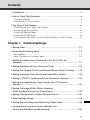
Contents
Introduction ..............................................................................................ii
How to Read This Document ..................................................................ix
Operation Manuals ............................................................................................ ix
Icons Used in This Document ............................................................................x
Top Page of the Camera .........................................................................xi
Accessing the Top Page of the Camera ........................................................... xi
Accessing the Setting Menu ............................................................................ xii
Accessing Sample Pages ................................................................................ xii
Accessing VB-C60 Viewer .............................................................................. xiii
User Authentication When Accessing Setting Menu or Admin Viewer ........... xiv
Chapter 1
Detailed Settings
Setting Menu ........................................................................................ 1-2
Accessing the Setting Menu ................................................................ 1-4
Setting Menu .................................................................................................. 1-4
Items Common to All Setting Pages ............................................................... 1-5
Setting the Administrator Password, LAN, IPv6, DNS, etc.
(Network) ............................................................................................. 1-7
Setting the Date and Time (Date and Time) ...................................... 1-12
Setting the Camera Control and External Device Name (Camera) .... 1-14
Setting the Image Size, Quality and Frame Rate (Video) .................. 1-22
Setting HTTP/FTP Upload and E-mail Notification (Upload) .............. 1-24
Setting the Image Server, Audio Server and HTTP Server
(Server) .............................................................................................. 1-30
Setting the Image Buffer, Motion Detection,
Audio Playback and Interval Timer (Event) ........................................ 1-34
Setting User Access Privileges (Access Control) ............................... 1-40
IPsec Settings (IPsec) ........................................................................ 1-44
Setting the Items Requiring Rebooting (Reboot Item) ....................... 1-48
Viewing Event Logs and Current Settings, and
Performing Maintenance (Maintenance) ........................................... 1-50
v
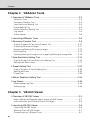
Contents
Chapter 2
VBAdmin Tools
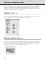
Overview of VBAdmin Tools ................................................................ 2-2
VBAdmin Tools ............................................................................................... 2-2
Panorama Creation Tool ................................................................................. 2-2
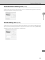
View Restriction Setting Tool .......................................................................... 2-3
Preset Setting Tool ......................................................................................... 2-3
Motion Detection Setting Tool ........................................................................ 2-4
Log Viewer ..................................................................................................... 2-4
Admin Viewer ................................................................................................. 2-5
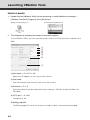
Launching VBAdmin Tools ................................................................... 2-6
Panorama Creation Tool ...................................................................... 2-9
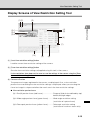
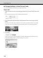
Display Screens of Panorama Creation Tool ............................................... 2-10
Capturing Panorama Images ....................................................................... 2-11
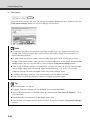
Registering/Deleting Panorama Images ...................................................... 2-12
Reconnecting ............................................................................................... 2-13
Opening Panorama Images from Image Files/Saving as Image Files ......... 2-13
View Restriction Setting Tool ............................................................. 2-14
Display Screens of View Restriction Setting Tool ......................................... 2-15
Setting View Restrictions .............................................................................. 2-17
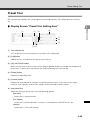
Preset Setting Tool ............................................................................ 2-22
Display Screens of Preset Setting Tool ........................................................ 2-23
Setting the Preset ......................................................................................... 2-25
Preset Tour ................................................................................................... 2-29
Motion Detection Setting Tool ............................................................ 2-34
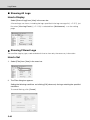
Log Viewer ......................................................................................... 2-45
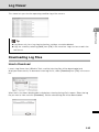
Downloading Log Files ................................................................................. 2-45
Viewing Logs ............................................................................................... 2-46
Chapter 3
VB-C60 Viewer
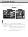
Overview of VB-C60 Viewer ................................................................ 3-2
Major Differences Between Admin Viewer and VB Viewer ............................ 3-2
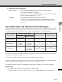
User Authorities and Camera Control Privileges ............................................ 3-3
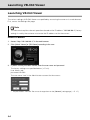
Launching VB-C60 Viewer ................................................................... 3-6
Launching VB-C60 Viewer ............................................................................. 3-6
Shutting Down VB-C60 Viewer ....................................................................... 3-7
Connecting from VBAdmin Tools ................................................................... 3-7
vi
Contents
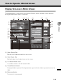
How to Operate VB-C60 Viewer .......................................................... 3-9
Display Screens of Admin Viewer .................................................................. 3-9
Display Screens of VB Viewer ...................................................................... 3-11
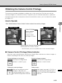
Obtaining the Camera Control Privilege ...................................................... 3-13
Control the camera ....................................................................................... 3-14
Setting Video and Audio .............................................................................. 3-18
Displaying Information ................................................................................. 3-21
Performing Operations and Settings as the Administrator ................. 3-23
Opening Control for Admin .......................................................................... 3-23
Operating the External Device Output ........................................................ 3-24
Displaying the External Device Input Status ................................................ 3-24
Displaying the Motion Detection Status ....................................................... 3-25
Controlling/Setting the Camera .................................................................... 3-25
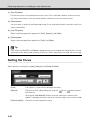
Setting the Focus ......................................................................................... 3-26
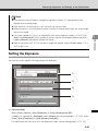
Setting the Exposure .................................................................................... 3-27
Setting the White Balance ........................................................................... 3-29
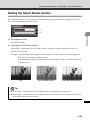
Setting the Smart Shade Control ................................................................. 3-31
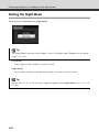
Setting the Night Mode ................................................................................ 3-32
Chapter 4
Creating Web Pages for Video Distribution
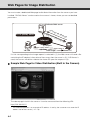
Web Pages for Image Distribution ....................................................... 4-2
Viewing Sample Pages ........................................................................ 4-4
Distributing Video Using VB Viewer ..................................................... 4-6
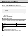
How to Create a Web Page Using VB Viewer ................................................ 4-6
Saving Web Page Data .................................................................................. 4-6
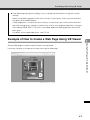
Example of How to Create a Web Page Using VB Viewer ............................. 4-7
VB Viewer Parameters .................................................................................... 4-9
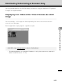
Distributing Video Using a Browser Only ........................................... 4-11
Displaying Live Video at the Time of Access as a Still Image ..................... 4-11
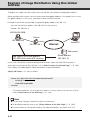
Example of Image Distribution Using One Global Address ................ 4-12
Distributing Still Images to Mobile Phones ......................................... 4-13
Overwriting a Sample Page ......................................................................... 4-14
vii
Contents
Chapter 5
Appendix
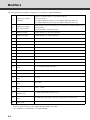
Modifiers .............................................................................................. 5-2
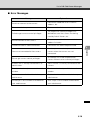
Troubleshooting ................................................................................... 5-4
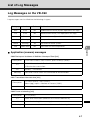
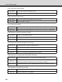
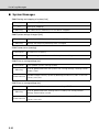
List of Log Messages ........................................................................... 5-7
Log Messages on the VB-C60 ....................................................................... 5-7
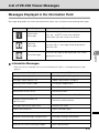
List of VB-C60 Viewer Messages ...................................................... 5-17
Messages Displayed in the Information Field .............................................. 5-17
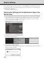
Restore Settings ................................................................................ 5-20
Restoring the Settings from the Maintenance Page in the Web Browser .... 5-20
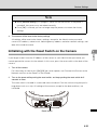
Initializing with the Reset Switch on the Camera ......................................... 5-21
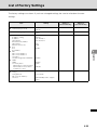
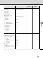
List of Factory Settings ...................................................................... 5-23
Index .................................................................................................. 5-31
viii
How to Read This Document
Operation Manuals
This camera comes with Start Guide, and Operation Guide (this document) included in Setup
CD-ROM.
Start Guide (Bundled)
The safety precautions to be followed when using the VB-C60, types of bundled software,
operating environment, initial settings of the camera, installation method, etc., are
explained. The Start Guide comes with the VB-C60. In this manual, items that should be
referenced in the Start Guide are described as follows. See "Features of VB-C60" (
Start
Guide).
Operation Guide (this document) (VBC60OG_E.pdf)
The document explains the basic setting procedures for the VB-C60, how to use it,
VBAdmin Tools and VB-C60 Viewer, troubleshooting, etc. This document is included in
the Setup CD-ROM.
Also, a simplified version of the recording software RM-Lite ( Start Guide "Network Video
Recording Software RM-Lite") is stored in the Setup CD-ROM. The following operation manuals
are available:
Administrator’s Manual (RM10AM_E.pdf)
This document explains the items to note when using RM-Lite, as well as operating
environment requirements, system configuration, installation and setup methods, and
other details on how to use the software. Be sure to read this document.
Viewer Operation Guide (RM10VOG_E.pdf)
This document explains a basic operation of the RM-Lite Viewer. For the detailed
operating procedures of the viewer, refer to Administrator’s Manual.
ix
How to Read This Document
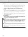
Icons Used in This Document
This document uses the following icons to indicate particularly important information the user
should read.
Icon
Meaning
Inappropriate handling against the instruction accompanied by this
Caution
icon may result in property damage. Be sure to observe these
precautions.
An important item or prohibited item that should always be
Note
observed during operation is explained. Be sure to read these
instructions to prevent mechanical failure or damage.
Tip
x
Supplementary information or a reference to the operation is
explained. Users are recommended to read these memos.
Top Page of the Camera
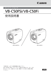
The top page of the VB-C60 showing the Setting Menu, VB-C60 Viewer display, etc., is explained.
Access the top page of the camera in the web browser.
From the top page of the camera, you can access VB-C60 Viewer for displaying images and the
Setting Menu that lets you specify detailed settings of the VB-C60.
If you are accessing the camera for the first time, see the Start Guide bundled with the camera.
Note
This document explains relevant operations based on the IP address 192.168.100.1 (factory
setting). In reality, the customer must enter the IP address set for the camera.
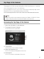
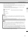
Accessing the Top Page of the Camera
1. Access "http://192.168.100.1/" via the web browser.
2. The top page of the camera is displayed.
An overview of each link is given below.
(1)
(2)
(3)
(4)
(1) Language Button
Use this button to switch the display language.
(2) Setting Page (Setting Menu) Link
Click this link to display the Setting Menu of the camera.
(3) Sample page link
Click this link to display sample pages of the camera.
xi
Top Page of the Camera
(4) VB-C60 Viewer launch link
Clicking this link launches VB-C60 Viewer, which displays the image captured by the camera
in the web browser.
VB-C60 Viewer consists of two viewers: [Admin Viewer] and [VB Viewer] (
P. 3-2).
z Explanation of each link
[Admin Viewer]
Launches Admin Viewer.
[VB Viewer]
Launches VB Viewer.
Accessing the Setting Menu
To specify detailed settings of the VB-C60, click (2) to proceed to the Setting Menu. For details on
the Setting Menu, see "Setting Menu" in "Chapter 1 Detailed Settings" (
P. 1-2).
Accessing Sample Pages
To access a sample page, click (3).
One of three sample pages, each showing a still image, video or image for mobile phone, can be
displayed.
Tip
For specific instructions on how to use the sample pages, see "Chapter 4 Creating Web
Pages for Video Distribution" (
xii
P. 4-2).
Top Page of the Camera
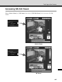
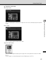
Accessing VB-C60 Viewer
Select [Admin Viewer] or [VB Viewer] from the (4) [VB-C60 Viewer] links to access VB-C60
Viewer.
Admin Viewer
VB Viewer
xiii
Top Page of the Camera
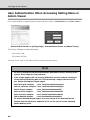
User Authentication When Accessing Setting Menu or
Admin Viewer
User authentication is required when accessing the camera's [Setting Menu] or [Admin Viewer].
Authentication Screen on [Setting Page] Authentication Screen on [Admin Viewer]
The factory settings are specified below.
User name: root
Password: VB-C60
The user name "root" is the Administrator account for the camera.
Note
• Be sure to change the default Administrator password to ensure security of the
system. Don't forget the new password.
• If the sample pages (
P. 4-4) must be deleted for security reasons, access the
file found at the following path via FTP and back up a copy of the file to a PC,
etc., before deleting the sample pages.
Path to English samples
: /mnt_flash/www/html/sample/en/
Path to Japanese samples : /mnt_flash/www/html/sample/ja/
Path to French samples
: /mnt_flash/www/html/sample/fr/
Path to Italian samples
: /mnt_flash/www/html/sample/it/
Path to German samples
: /mnt_flash/www/html/sample/de/
Path to Spanish samples
: /mnt_flash/www/html/sample/es/
To restore deleted sample pages, you must rewrite to the above paths the
backup files that have been copied to a PC, etc. Be sure to create a backup
before deleting a file.
xiv
Top Page of the Camera
Note
z If the Administrator and Authorized User are sharing VB-C60 Viewer on the same PC, it is
strongly recommended that the [Remember my password] check box be cleared.
z If a wrong user name or password is entered, the camera cannot be connected. Connect
the camera by entering the correct user name and password.
z If you have forgotten the Administrator Password, press the reset switch to initialize the
settings. See "Initializing with the Reset Switch on the Camera" (
P. 5-21). Take note,
however, that this will reset all settings of the camera, except for time and date, to their
factory settings.
Tip
For details on VB-C60 Viewer and user types, see "Overview of VB-C60 Viewer" in "Chapter 3
VB-C60 Viewer" (
P. 3-2).
xv
Top Page of the Camera
xvi
Detailed Settings
The following explains the detailed settings on network
connection, camera control, date & time, access control, etc.
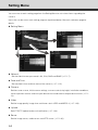
Setting Menu
You can move to each setting page from the Setting Menu to set various items regarding the
camera.
Items that can be set on each setting page are explained below. See each reference page for
details.
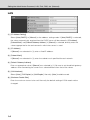
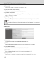
z Setting Menu
z Network
Set the Administrator password, LAN, IPv6, DNS and SNMP (
P. 1-7).
z Date and Time
Set the date & time and time zone of the camera (
P. 1-12).
z Camera
Set the camera name, initial camera settings, camera control, day/night, installation conditions,
camera position control, external input device name and external output device name (
14).
z Video
Set the image quality, image size and frame rate in JPEG and MPEG-4 (
z Upload
Set HTTP/FTP upload and e-mail notification (
P. 1-24).
z Server
Set the image server, audio server and HTTP server (
1-2
P. 1-30).
P. 1-22).
P. 1-
Setting Menu
z Event
Set the image buffer, motion detection, external device input, interval timer and audio file
upload (
P. 1-34).
1
Set the authorized user accounts, user privileges and host access restriction (
Detailed Settings
z Access Control
P. 1-40).
z IPsec
IPsec configuration (
P. 1-44).
z Reboot Item
Set items requiring rebooting (reboot items) (
P. 1-48).
z Maintenance
"Tool" (View Log Events, View Current Settings, Reboot, Restore Settings) (
P. 1-50).
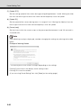
Note
Notes on Use with Windows Vista/XP
z When the [Windows Security Alert] dialog box appears, click the [Unblock] button.
Once this button is clicked, this warning dialog box will no longer appear.
z If the dialog box appears and pop-up is blocked when accessing [HELP] of each setting
page or [View Log Events] or [View Current Settings] on the maintenance page, enable
[Pop-up] by following the procedure explained in the information bar.
1-3
Accessing the Setting Menu
The various settings of the VB-C60 are specified by accessing the camera in the web browser.
First, access the top page (
P. xi).
For entry of the user name and password, see (
P. xiv).
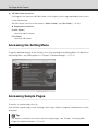
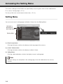
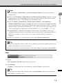
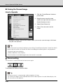
Setting Menu
You can access each setting page and Admin Viewer from the Setting Menu.
“VB-C60” is
displayed as
the model name.
Setting Menu
(1) [Back to top] button
Clicking this button switches the display to the top page of the camera.
(2) [Admin Viewer] button
Clicking this button switches the display to Admin Viewer.
(3) Setting Menu
Clicking a desired button switches the display to each setting page.
Note
Once all settings are complete on the setting page, close the web browser for security
reasons.
1-4
Accessing the Setting Menu
Items Common to All Setting Pages
1
Application of Setting Changes
the top right of the setting page turns blue.
To make the new setting effective, click the [Apply] button.
To restore the original setting, click the [Clear] button.
Setting Changes Requiring Rebooting
The items whose setting will become effective only after the camera is rebooted are
accompanied by an orange icon.
If any item accompanied by an orange icon is changed, the [Apply] button shown on the top
right of each setting page changes to [Apply and reboot].
To confirm the new setting, click the [Apply and reboot] button. The new setting will be
reflected and the camera will be rebooted.
To restore the original setting, click the [Clear] button.
Note
If you switch to a different setting page without clicking the [Apply] button or [Apply and
reboot] button, the changes you have made will be lost. To make the changes effective, be
sure to click the [Apply] button or [Apply and reboot] button.
1-5
Detailed Settings
When any setting is changed on each setting page, the grayed-out [Apply] button shown on
Accessing the Setting Menu
Returning to the Setting Menu
To return to the Setting Menu from each setting page, click the [Settings menu] button on the
top right of the setting page.
Note
z Be sure to change the settings of each camera within one setting page.
z Do not move between setting pages using the [Back] and [Forward] buttons of the browser.
The new settings may return to the original settings or unwanted setting changes may
occur.
Tip
Click
[Help] at the beginning of any item on a setting page to display a detailed
explanation of the setting item.
1-6
Setting the Administrator Password, LAN, IPv6,
DNS, etc. (Network)
1
Detailed Settings
You can set the following items.
z Administrator Password
Set the Administrator password.
z LAN
Set the IP address and other items needed to establish LAN connection.
z IPv6
Set IPv6.
z DNS
Set the name server address, host name and DDNS.
z SNMP
Set the SNMP.
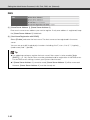
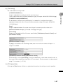
Administrator Password
(1) [Password]
Set the Administrator password. You can use up to eight (single-byte) ASCII characters
(space or printable characters). The factory setting is "VB-C60." If Admin Viewer or VBAdmin
Tools is connected, change the password after terminating the connection.
(2) [Confirm Password]
Enter the same password for confirmation.
Note
z Be sure to change the default Administrator password to ensure security of the system.
Don't forget the new password.
z If you have forgotten the Administrator Password, press the reset switch to initialize the
settings. See "Initializing with the Reset Switch on the Camera" (
P. 5-21). Take note,
however, that this will reset all settings of the camera, except for time and date, to their
factory settings.
1-7
Setting the Administrator Password, LAN, IPv6, DNS, etc. (Network)
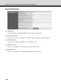
LAN
(1) [IP Address Setting]
Select [Auto (DHCP)] or [Manual] as the address setting mode. If [Auto (DHCP)] is selected,
the values automatically acquired from the DHCP server will be entered in [IP Address],
[Subnet Mask] and [Default Gateway Address]. If [Manual] is selected, directly enter the
values appropriate for the environment in which the camera is used.
(2) [IP Address]
If [Manual] was selected in (1), enter a fixed IP address.
(3) [Subnet Mask]
If [Manual] was selected in (1), enter the subnet mask specified for each network.
(4) [Default Gateway Address]
Enter an appropriate value if [Manual] was selected in (1). Be sure to set the default gateway
address when connecting the camera to a subnet different from that of the viewer.
(5) [LAN Interface]
Select [Auto], [Full Duplex] or [Half Duplex]. Normally [Auto] should be used.
(6) [Maximum Packet Size]
Enter the maximum transmission unit. Normally the default setting of 1500 needs not be
changed.
1-8
Setting the Administrator Password, LAN, IPv6, DNS, etc. (Network)
Note
z For [IP Address], [Subnet Mask] and [Default Gateway Address], contact your network
1
administrator.
network access may be disabled. In this case, use VB Initial Setting Tool ("Perform Initial
Setting of the Camera" in Start Guide) to set the address again.
z If the [IP Address], [Subnet Mask], [Default Gateway Address], [LAN Interface] or
[Maximum Packet Size] setting is changed, the camera may become no longer accessible
from the active browser. Check beforehand the precautions explained in "Notes" in "Setting
the Items Requiring Rebooting (Reboot Item)" (
P. 1-49). Also check the precautions in the
same section before changing each setting in "[IPv6]" (
P. 1-9) and "DNS" (
P. 1-10).
z If [Auto (DHCP)] is selected as the address setting mode, the IP address may not be
assigned correctly in certain environments, such as when a router is present between the
DHCP server and this camera. In this case, assign a fixed IP address by selecting
[Manual].
z If you are using IPv6, set 1280 or greater value under [Maximum Packet Size].
Tip
z If you are using optical fiber or ADSL, you may be able to improve the sending efficiency by
slightly reducing the maximum packet size.
z You can use the VB Initial Setting Tool to check the IP address assigned by [Auto (DHCP)].
IPv6
(1) [IPv6]
Select [Disable] or [Enable] regarding the use of IPv6.
(2) [IPv6 Address]
If [Enable] is selected for IPv6, an automatically acquired address will be shown.
Tip
In an environment where IPv6 cannot be used, the [IPv6 Address] field remains blank even
when [Used] is selected for IPv6.
1-9
Detailed Settings
z If any of the [IP Address], [Subnet Mask] and [Default Gateway Address] settings is wrong,
Setting the Administrator Password, LAN, IPv6, DNS, etc. (Network)
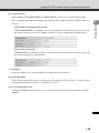
DNS
(1) [Name Server Address 1], [Name Server Address 2]
Enter each name server address you want to register. If only one address is registered, keep
the [Name Server Address 2] field blank.
(2) [Host Name Registration with DDNS]
Select [Enable] and enter the host name. The host name can be registered in the name
server.
You can use up to 63 (single-byte) characters including A to Z, a to z, 0 to 9, "-" (hyphen), _
(underscore) and "." (period).
Tip
z For added convenience, register the host name if the camera is to be used by [Auto
(DHCP)] (
P. 1-8). Certain items must be set beforehand for registration in the DNS server.
For the DNS server settings, contact your System Administrator.
z If [Name Server Address 1] cannot be used, [Name Server Address 2] will be accessed.
However, [Name Server Address 2] must be already set.
1-10
Setting the Administrator Password, LAN, IPv6, DNS, etc. (Network)
SNMP
1
Select whether to use SNMP from [Disable] or [Enable]. When [Enable] is selected, the SNMP
Manager can reference information set in the camera.
(2) [Community Name]
Set a community name for SNMP. It is recommended that you change the default community
name to ensure security of the system.
(3) [Administrator Contact Information]
Set contact information (e-mail address, etc.) for the Administrator of the camera. The
settings can be referenced by the SNMP Manager.
(4) [Administration Function Name]
Set the camera name used for administration. The settings can be referenced by the SNMP
Manager.
If this field is left blank, "VB-C60" will be used by default.
(5) [Installation Location]
Set information regarding the installation location of this camera. The settings can be
referenced by the SNMP Manager.
Tip
z The information set in the camera is read-only from the SNMP Manager.
z Use the SNMP Manager SNMP MIB2 (supporting RFC1213).
z The camera's SNMP does not support IPv6.
1-11
Detailed Settings
(1) [SNMP]
Setting the Date and Time (Date and Time)
You can set the following items.
z Current Date and Time
The date and time set in the camera is shown.
z Setting
Select the date & time setting method and time zone for this camera.
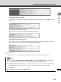
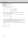
Current Date and Time
[Date], [Time]
The date and time currently set in the camera is shown.
Setting
(1) [Setting Method]
Select [Set manually], [Synchronize with NTP server], [Synchronize with NTP broadcast] or
[Synchronize with computer time].
(2) [Date], [Time]
Set the following items according to the selection for [Setting Method] made in (1).
[Set manually]
You can set a desired date and time. Enter the date in the order of <year/month/day> and
time in the order of <hours:minutes:second> in the 24-hour format. (Two digits each for
month, day, and hour.)
Example: To specify August 23, 2008 1:23:04 pm, enter "2008/08/23" and "13:23:04."
1-12
Setting the Date and Time (Date and Time)
1
The camera will synchronize with that time of the NTP server. Enter the IP address of the
NTP server.
[Synchronize with NTP broadcast]
The camera will synchronize with the NTP broadcast time.
[Synchronize with computer time]
The camera will synchronize with the date and time of the computer currently accessing
the camera. The time zone will also be selected automatically.
(3) [Time Zone]
Select from the list an applicable time difference from the Greenwich Mean Time.
Tip
z If you select [Synchronize with computer time], clicking the [Apply] button to apply the
setting will set the setting shown under [Setting Method] to [Set manually].
z If [Synchronize with NTP Server] is selected, the date and time will not be changed when
the IP address of the NTP server is wrong or otherwise the NTP server cannot be
connected.
z The camera's NTP does not support IPv6.
1-13
Detailed Settings
[Synchronize with NTP server]
Setting the Camera Control and External Device
Name (Camera)
You can set the following items.
z Camera Name
Enter the name of the camera. The camera name is required if the RM-series software
is used with the camera.
z Initial Camera Settings
Set the AE mode, slow shutter, shutter speed and focus mode.
z Camera Control
Set the digital zoom and image stabilizer.
z Day/Night
Set the Day/Night switching mode.
z Installation Conditions
Set whether or not you will use a dome, the LED setting, and the mounting method.
z Camera Position Control
Set whether or not to limit the camera's pan/tilt/zoom operations to the preset
positions registered beforehand. Also, set the operation to be performed when
control privileges are not requested.
z External Device Name
Set the external input device name and external output device name.
General
[Camera Name]
Be sure to enter the camera name into [Camera Name (alphanumeric characters)].
Up to 15 ASCII characters (spaces or printable characters) can be used for the [Camera
Name (alphanumeric characters)].
Tip
If you are using the optional recording software (RM-64/RM-25/RM-9 or bundled RM-Lite), the
camera name set here will be shown when the camera is registered.
1-14
Setting the Camera Control and External Device Name (Camera)
Initial Camera Settings
1
Detailed Settings
(1) [AE Mode], [Slow Shutter], [Shutter Speed]
Set the camera exposure control and shutter speed.
[AE Mode]
[Auto]
The exposure is controlled automatically.
[Flickerless]
In this mode, image flickers caused by fluorescent lights, etc., can be reduced. The
shutter speed is automatically adjusted according to the brightness of the environment in
which the camera is used.
[Shutter-priority AE]
In this mode, a desired shutter speed can be specified.
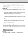
[Slow Shutter]
Slow shutter can be set only when [Auto] is selected under [AE Mode].
Set the maximum slow shutter time to be used in the auto exposure mode when capturing
video in a dark place. Select [Disable], [1/15] or [1/8]. The longer the shutter time, the more
likely a residual image generates when a moving subject is captured. Accordingly, select an
appropriate time according to the capture condition.
[Shutter Speed]
Shutter Speed can be set only when [Auto (Shutter-priority AE)] is selected under [AE
Mode]. Select a desired shutter speed of the camera from the 12 levels from [1/8] to [1/
8000]. When capturing a moving subject, selecting a higher shutter speed lets you
capture less blurry image.
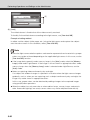
(2) [Focus Mode]
Set the focus mode of the camera.
[Auto]
The subject is automatically brought into focus. Normally [Auto] should be selected.
[Fixed at infinity]
The focus can be fixed to near infinity.
1-15
Setting the Camera Control and External Device Name (Camera)
Note
z Where an outdoor scene is captured from inside a room through a glass window, etc., the
camera may focus on the glass surface if there is dust or water on the glass surface. In this
case, use the camera by installing it at the shortest possible distance (within 30 cm) from
the glass surface.
z The initial camera settings (1) and (2) define the defaults that apply when the camera is
started. Setting changes will be reflected only after the camera is reconnected or camera is
rebooted.
Specify the settings used in the actual operating environment, using Control for Admin in
VB-C60 Viewer. See "Opening Control for Admin" (
P. 3-23).
z If the subject is a traffic signal, electronic scoreboard, etc., the captured image may flicker.
In this case, try changing the [AE Mode] setting to [Auto (Shutter-priority AE)] and selecting
a shutter speed lower than 1/100, to see if the problem improves.
1-16
Setting the Camera Control and External Device Name (Camera)
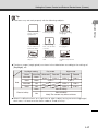
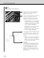
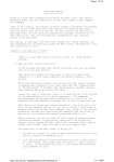
Tip
z Auto focus may not work properly with the following subjects:
1
Detailed Settings
A white wall or other subject
having no contrasting
bright/dark areas
A slanting subject
A subject reflecting
strong light
A subject consisting
only of slant lines or
horizontal stripes
A subject having no
form, such as flame
or smoke
A subject seen
through glass
A fast-moving
subject
A dark area or night
view
A subject that is
simultaneously far and
near
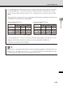
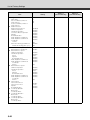
z The focus ranges (rough guide) are shown in the table below according to the settings of
[Day/Night], etc.
Day/Night setting
Auto
Day mode
Night mode
Dome
Infrared lamp
Wide end
Tele end
Wide end
Tele end
Not used
None
0.3m~∞
1.5m~∞
0.5m~∞
1.8m~∞
Used
None
Not used
Yes
0.5m~∞
1.8m~∞
Used
Yes
0.5m~∞
2.4m~∞
Fixed at infinity
2.1m~∞
2.4m~∞
None
Point of infinity
Yes
Point of infinity
Note) The camera may be out of focus.
z When it is difficult to focus on a night view or other subject having no contrasting bright/
dark areas, it is best to set the focus mode to "Fixed at infinity."
1-17
Setting the Camera Control and External Device Name (Camera)
Camera Control
(1) [Digital Zoom]
Select [Enable] or [Disable] for digital zoom.
* The higher the digital zoom ratio, the lower the image quality becomes.
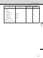
(2) [Image Stabilizer]
Select the image stabilizer setting from among the following: [Disable], [On1] and [On2]. The
Image Stabilizer has the effect of correcting blurry images. If you selected [On1] but the
image is still blurry, try using [On2].
If you select [On1] or [On2] as the image stabilizer setting, the viewing angle will be smaller
and the image more coarse than when [Disable] is selected. This is not a malfunction.
Compensable level
of blurriness
Viewing angle ratio
Effective pixels
Disable
―
100%
Approx. 310,000 pixels
On1
Small
83%
Approx. 210,000 pixels
On2
Large
50%
Approx. 80,000 pixels
Note
z If you use [On2], it is best to select a received image size smaller than "320 x 240".
z The Image Stabilizer is not effective when the subject is shaking.
z Image Stabilizer does not work against significant vibration exceeding a certain level or
momentary vibration.
z See P. 3-22 for the notes on using the viewer when the Image Stabilizer is set.
1-18
Setting the Camera Control and External Device Name (Camera)
Day/Night
1
Select [Manual] or [Auto] as the Day/Night mode.
If you have selected [Manual], you can manually switch between [Day Mode] and [Night
Mode] using Night mode on Admin Viewer (P. 3-32).
If you have selected [Auto], set [Switching Brightness] and [Response (sec.)] according to
the environment in which the camera is installed as well as the desired switching conditions.
* [Auto] cannot be used in an environment where infrared illumination is also used.
(2) [Switching Brightness]
Set the brightness at which the Day mode and Night mode will be switched. Select [Darker],
[Slightly Darker], [Standard], [Slightly Brighter] or [Brighter]. Select [Darker] to capture video
in color whenever possible.
Select [Brighter] to reduce noise. Note that this will cause the camera to switch to black &
white earlier.
(3) [Response (sec.)]
Set the time in seconds needed to make judgment on day/night mode switching. Select [5],
[10], [20], [30] or [60].
If the brightness remains above or below the level set in (2) for the number of seconds set
above, the day mode and night mode will switch.
If the brightness changes frequently, such as when a light source passes in front of the
camera, select [30] or [60]. If the change in brightness is minimal, select [5] or [10].
Note
z If you want to set [Auto] for [Day/Night], conduct a thorough operation test and check the
effectiveness of the setting beforehand.
z If [Auto] is selected under [Day/Night], set [Exposure] of VB-C60 Viewer to [Auto], [Auto
(Flickerless)] or [Auto (Shutter-priority AE)] (
P. 3-27).
z If infrared illumination is also used, set [Manual] under [Day/Night]. It cannot be used in
[Auto].
z If [Auto] is set under [Day/Night], the infrared cutoff filter may move several times back and
forth while the mode is being switched between [Day Mode] and [Night Mode]. Pan, tilt,
zoom and manual focus do not work during this period.
1-19
Detailed Settings
(1) [Mode]
Setting the Camera Control and External Device Name (Camera)
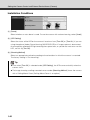
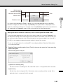
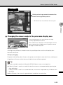
Installation Conditions
(1) [Dome]
Select whether or not a dome is used. To use the camera with a dome housing, select [Used].
(2) [LED Setting]
Select the status of the LEDon the camera's head arm from [Turn Off] or [Turn On]. If you are
using the optional Indoor Dome Housing (VB-RD51S-C/S) or if image capture is obstructed,
for example by reflected LED light entering the capture area, or you do not want to turn on the
LED, set this to [Turn Off].
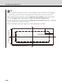
(3) [Mounting Method]
Select an appropriate method according to the orientation in which the camera is mounted.
The factory setting is "On the ceiling."
Tip
z Even when [Turn Off] is selected under [LED Setting], the LED comes on briefly when the
camera starts.
z The image showing a ceiling-mounted camera under [Mounting Method] shows the camera
with a Ceiling Mount Cover (Ceiling Mount Cover is an option).
1-20
Setting the Camera Control and External Device Name (Camera)
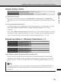
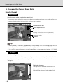
Camera Position Control
1
Select the camera control preset from [No Restriction] or [Preset Only]. If [Preset Only] is
selected, you can limit the camera control by any non-administrator user to the preset angles
only.
(2) [Camera Position without Control]
If control privileges are not requested when the home position has already been set, select
either [Do not return to Home Position] or [Return to Home Position] as the camera
movement.
If you select [Return to Home Position] and no one has camera control privileges, the camera
automatically moves to the home position. To use this function, set the home position of the
camera in advance. Set the home position using "Preset Setting Tool" (
P. 2-22).
External Input Device 1, 2/External Output Device 1, 2
[Device Name] for external input device/external output device
Be sure to enter each device name to identify the corresponding external device being
connected. Enter the device name (single-byte alphanumerics) using up to 15 characters
(ASCII characters (space or printable characters) excluding a double quotation mark (")).
Tip
If you are using Admin Viewer and an optional recording software (RM-64/RM-25/RM-9 or
bundled RM-Lite), the external device name set here will be shown when the camera is
registered.
1-21
Detailed Settings
(1) [Restricted to Presets]
Setting the Image Size, Quality and Frame Rate
(Video)
You can set the following items.
z JPEG
Set the image quality, size and maximum frame rate in JPEG.
z MPEG-4
Set the video quality, size and capture frame rate in MPEG-4.
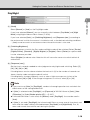
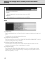
JPEG
(1) [Image Quality]
Select a desired quality from 1 to 5 (total 5 levels) for image transmitted at each image size in
JPEG.
The greater the value, the higher the quality becomes.
(2) [Image Size: Image Transmission]
Select the image transmission size from [160 x 120], [320 x 240] and [640 x 480]. The default
image size used by each viewer is selected.
(3) [Maximum Frame Rate: Image Transmission]
Limit the maximum transmission frame rate per second to reduce the viewer load. The
maximum is 30 frames/sec. Enter a value between 0.1 and 30.0.
(4) [Image Size: Upload]
Select [160 x 120], [320 x 240] or [640 x 480] for the size of transmitted image using the
upload function. For details of upload settings, see "Setting HTTP/FTP Upload and E-mail
Notification (Upload)" (
1-22
P. 1-24).
Setting the Image Size, Quality and Frame Rate (Video)
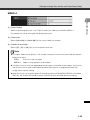
MPEG-4
1
Detailed Settings
(1) [Video Quality]
Select a desired quality from 1 to 5 (total 5 levels) for video transmitted in MPEG-4.
The greater the value, the higher the quality becomes.
(2) [Video size]
Select [320 x 240] or [640 x 480] for the size of video transmitted.
(3) [Capture Frame Rate]
Select [10], [15] or [30] (fps) as the capture frame rate.
Note
z If a higher video size or quality is set, the data size per frame will increase and the network
load will increase.
JPEG
: The frame rate may drop.
MPEG-4 : Video may be temporarily disrupted.
z The data size may increase depending on the type or movement of the subject. If the frame
rate remains low or other undesirable condition continues for a long period, lower the
image size or quality setting.
z Note that if you are using the optional recording software (RM-64/RM-25/RM-9 or bundled
RM-Lite), the amount of hard disk space used will also be affected during recording.
1-23
Setting HTTP/FTP Upload and E-mail Notification
(Upload)
You can set the following items.
z General Upload
Set the upload operations.
z HTTP Upload
Set the upload via HTTP connection.
z FTP Upload
Set the upload via FTP connection.
z E-mail Notification
Set items relating to sending of event information and video by e-mail.
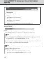
General Upload
[Upload]
Select [Upload Disabled], [HTTP Upload] or [FTP Upload] as the upload mode.
Note
z To use the upload function, the [Event] menu must also be set (
P. 1-34).
z If you are using both e-mail notification by text with image and image upload by HTTP/FTP,
set [320 x 240] or less under [Image Size: Upload] (
P. 1-22)
z If you set the camera to perform upload or e-mail notification continuously, some images or
e-mails may not be sent properly, depending on the image size and network conditions to
the server. In this case, an event log message is displayed.
Tip
To lower the upload or e-mail notification load, try the following measures. Also check the
settings including network to the server.
z Reduce the image file size:
1-24
-
Set a lower value under [Image Quality] for JPEG (
-
Set a lower value for [Image Size: Upload] for JPEG (
P. 1-22).
P. 1-22).
Setting HTTP/FTP Upload and E-mail Notification (Upload)
z Reduce the uploading frequency:
- Reduce the value in [Pre-event Buffer (number of image frames)] or [Post-event Buffer
(number of image frames)] ( P. 1-34).
1
- If [Motion Detection Event] is enabled, disable [ON Event Operation], [OFF Event
- If [External Device Input Event] is enabled, disable [ON Event Operation] or [OFF Event
Operation] ( P. 1-37).
- If [Interval Timer Event] is enabled, increase the value in [Interval of the Timer] ( P. 138).
z Reduce the e-mail notification frequency:
- If [Motion Detection Event] is enabled, disable [ON Event Operation], [OFF Event
Operation] or [Continuous Motion Operation] ( P. 1-35).
- If [External Device Input Event] is enabled, disable [ON Event Operation] or [OFF Event
Operation] ( P. 1-37).
- If [Interval Timer Event] is enabled, increase the value in [Interval of the Timer] ( P. 138).
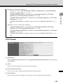
HTTP Upload
(1) [Notification]
Select [Notification Only with HTTP] or [Image attached Notification with HTTP] as the content
of notification.
(2) [URI]
Enter the URI to upload to (using up to 255 characters).
(3) [User Name], [Password]
Enter the user name and password required for authentication.
(4) [Proxy Server]
Enter the host name or IP address of the proxy server (using up to 63 characters).
1-25
Detailed Settings
Operation] or [Continuous Motion Operation] ( P. 1-35).
Setting HTTP/FTP Upload and E-mail Notification (Upload)
(5) [Proxy Port]
Enter the port number of the proxy server (default = "80").
(6) [Proxy User Name], [Proxy Password]
Enter the user name and password of the proxy server.
(7) [Parameter (query string)]
Enter an appropriate parameter (using up to 127 characters). The parameter can be entered
using "%" characters (
P. 5-2).
(8) [HTTP Upload Test]
Clicking the [Exec] button initiates an upload test based on the settings currently applied.
Note
Enter [Proxy Server], [Proxy Port], [Proxy User Name] and [Proxy Password] if connecting via
a proxy.
FTP Upload
(1) [Notification]
The notification setting is set to [Image data upload with FTP].
(2) [FTP Server]
Enter the host name or IP address of the FTP server (using up to 63 characters).
(3) [User Name], [Password]
Enter the user name and password required for authentication.
(4) [PASV Mode]
Select [Enable] or [Disable] for the PASV mode when uploading via FTP.
(5) [File Upload Path]
Enter the path to the folder to upload the image file to (using up to 255 characters).
1-26
Setting HTTP/FTP Upload and E-mail Notification (Upload)
(6) [File Naming]
Set a desired file naming mode.
[YYMMDDHHMMSSms]
1
Image is uploaded according to the file name format of
[YYMMDD Directory/HHMMSSms]
A sub directory named "{year}{month}{day}" is created first, and then the image is
uploaded using the file name "{hour}{minute}{second}{ms}.jpg." (Example: 20080123/
112122000.jpg)
[Loop]
Image is updated under a file name consisting of a number up to the value set in
[Maximum Number of Loops]. (Example: 0000.jpg, 0001.jpg)
[User setting]
Images are uploaded with the file name specified by [Subdirectory Name to Create] and
[File Name to Create].
[Maximum Number of Loops]
If [Loop] is selected as the recording mode, enter the maximum number of loops in a
range of 0 to 9999.
[Subdirectory Name to Create], [File Name to Create]
If File Naming is set to [User Setting], enter the subdirectory name to be created as well as
the name of the created file (using up to 127 characters). Each parameter can be entered
using "%" characters (
P. 5-2).
(7) [FTP Upload Test]
Clicking the [Exec] button initiates an upload test based on the settings currently applied.
1-27
Detailed Settings
"{year}{month}{day}{hour}{minute}{second}{ms}.jpg." Example: 20080123112122000.jpg)
Setting HTTP/FTP Upload and E-mail Notification (Upload)
E-mail Notification
(1) [Notification]
Select [Text only] or [Text with image] as the content of notification.
(2) [Mail Server Name]
Enter the host name or IP address of the SMTP server (using up to 63 characters).
(3) [Mail Server Port]
Enter the port number of the SMTP server (default = "25").
(4) [Sender (From)]
Set the e-mail address of the sender (using up to 63 characters).
(5) [Recipient (To)]
Set the e-mail address of the recipient (using up to 63 characters).
1-28
Setting HTTP/FTP Upload and E-mail Notification (Upload)
(6) [Authentication]
Select [None], [POP before SMTP] or [SMTP-AUTH] as the e-mail authentication mode.
Set an appropriate mode according to the authentication mode used by the SMTP server to
send to.
If [POP before SMTP] is selected as the e-mail authentication mode, enter the user name,
password, and host name or IP address of the POP server, required for authentication.
[User Name], [Password]
If [SMTP-AUTH] is selected as the e-mail authentication method, enter the user name and
password required for authentication.
(7) [Subject]
Enter the subject of the e-mail to be sent (using up to 31 characters).
(8) [Message Body]
Enter the message (text) of the e-mail to be sent (using up to 255 characters). The test can be
entered by parameters having "%" characters (
P. 5-2).
(9) [E-mail Notification Test]
Clicking the [Exec] button initiates an e-mail notification test based on the settings currently
applied.
1-29
Detailed Settings
[User Name], [Password], [POP Server]
1
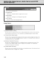
Setting the Image Server, Audio Server and HTTP
Server (Server)
You can set the following items.
z Image Server
Set the items needed to deliver image from the camera.
z Audio Server
Set the items relating to transmitting/receiving audio.
z HTTP Server
Set the HTTP port and web page delivery.
Image Server
(1) [Maximum Number of Clients]
Set the maximum number of clients that can be connected to the camera at the same time.
Up to 30 clients can be set. If 0 is set, connection is prohibited except for Admin Viewer.
(2) [Camera Control Queue Length]
Set the maximum queue length of requests for the camera control privilege from clients. The
maximum value is 30. Enter an integer between 0 and 30. If 0 is entered, camera control by
non-administrator users is prohibited.
(3) [Maximum Connection Time (sec.)]
Set the time in seconds during which an individual client can connect to the camera. The
maximum time is 65535 seconds. Enter an integer from 0 to 65535. If 0 is entered, the
connection time becomes unlimited.
(4) [Camera Control Time (sec.)]
Set the maximum time during which the viewer can control the camera. The maximum time is
3,600 seconds. Enter an integer from 1 to 3600.
1-30
Setting the Image Server, Audio Server and HTTP Server (Server)
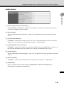
Audio Server
1
Detailed Settings
(1) [Audio Transmission from the Camera]
When [Enable] is selected, the audio input through the microphone attached to the camera
can be transmitted to VB-C60 Viewer.
(2) [Input Volume]
Set the audio input volume between 1 and 100. The greater the value, the larger the input
volume.
(3) [Voice Activity Detection]
If [Enable] is selected, the audio transmission size is reduced temporarily when no audio is
output. This way, the load of the applicable network can be reduced.
(4) [Audio Reception from the Viewer]
If [Enable] is selected, the audio from the optional RM Viewer or bundled RM-Lite Viewer can
be received and output from the speaker with amplifier connected to the camera.
(5) [Output Volume]
Set the audio output volume between 1 and 100. The greater the value, the larger the output
volume.
(6) [Echo Canceller]
If [Enable] is selected, echo between the microphone and speaker is suppressed.
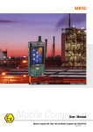
(7) [Audio Input]
Set the microphone input. Select [Line In], [Microphone In (dynamic microphone)] or
[Microphone In (condenser microphone)].
1-31
Setting the Image Server, Audio Server and HTTP Server (Server)
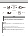
• Audio Transmission
• Input Volume
• Voice Activity Detection
• Echo Canceller
• Audio Reception
• Output Volume
Note
Switch [Line In] and [Microphone In] on each setting page according to the
specification of the microphone ( P. 1-31).
If a wrong input is used, the camera or microphone may be damaged. Be sure to
set the correct input.
Note
z The volume, sound quality, etc., may change depending on the characteristics of the
microphone used.
z To output audio from the audio output terminal of the camera, send audio from RM-Lite
Viewer. Audio cannot be sent from VB-C60 Viewer See "Audio Transmission/Reception
(Two-way Communication)" in RM-Lite Viewer ( Start Guide).
z Connect a speaker with an amplifier to the camera. See "Audio Input/Output Terminals" ( Start
Guide).
z If [Enable] is selected under [Echo Canceller], the sound quality or volume may be
affected. Utilize this function as necessary according to the installation environment and
how the camera is used.
z To transmit audio, read "Notes" in "Audio Input/Output Terminals" of Start Guide carefully.
1-32
Setting the Image Server, Audio Server and HTTP Server (Server)
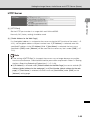
HTTP Server
1
Detailed Settings
(1) [HTTP Port]
Set the HTTP port number in a range of 80 and 1024 to 65535.
Normally "80" (factory setting) should be used.
(2) [Global Address for the Web Page]
If a fixed global address is assigned to the camera using the NAT function of the router (
P.
4-12), set the global address and port number here. If [IP Address] is selected, enter the
specified IP address in the [IP Address] field. If [Host Name] is selected, the host name
specified in [DNS] under [Network] will be used. Set the necessary items under [DNS] (
P.
1-10).
Note
z If the setting of [HTTP Port] is changed, the camera may no longer become accessible
from the active browser. Check beforehand the precautions explained in "Notes" in "Setting
the Items Requiring Rebooting (Reboot Item)" (
P. 1-49).
z If [IP Address] is selected under [Global Address for the Web Page], be sure to set both [IP
Address (global address for the web page)] and [Port Number (global address for the web
page)]. If [Host Name] is selected, also be sure to set [Host Name] under [DNS] on the
[Network] setting page.
1-33
Setting the Image Buffer, Motion Detection, Audio
Playback and Interval Timer (Event)
You can set the following items.
z Image Buffer
Set the items associated with the temporary saving of image in the image buffer.
z Motion Detection
Set the operation to be performed at the time of motion detection.
z External Device Input
Set the operation to be performed when an event is input from an external device.
z Interval Timer
Set the timer period for e-mail notification or upload.
z Sound Clip Upload
Set the audio file to be registered as a sound playback.
Image Buffer
(1) [Frame Rate]
Set the frame rate that applies when image is temporarily saved in the image buffer when an
event occurs.
(2) [Pre-event Buffer (number of image frames)]
Set the number of images to be buffered before the event.
(3) [Post-event Buffer (number of image frames)]
Set the number of images to be buffered after the event.
Note
z The maximum image buffer size is approx. 4 MB. If a large image size is set, the Frame
Rate, Pre-event Buffer and Post-event Buffer may not be achieved as specified (
P. 1-24).
z If buffering cannot be achieved as specified, an event log message appears. Before using
a large image size, confirm that no messages appear in the event log (
1-34
P. 1-24).
Setting the Image Buffer, Motion Detection, Audio Playback and Interval Timer (Event)
Tip
Regardless of the image buffer frame rate setting, only a single image will be uploaded when
a timer event occurs.
Detailed Settings
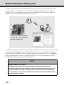
Motion Detection
(1) [Motion Detection Event]
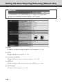
Shows whether motion detection events are enabled/disabled. To change this setting, use
Motion Detection Setting Tool in VBAdmin Tools (
1
P. 2-34). When motion detection events
are enabled, the camera provides event notification to a viewer capable of displaying the
detected event, such as the Admin Viewer.
(2) [ON Event Operation]
Select the operation to be performed upon an ON event. If [Enable] is selected, (5), "Upload"
and (6), "E-mail Notification" are displayed. When the mode changes to [Detected] (ON
event), the process set in (5) or (6) is performed.
(3) [OFF Event Operation]
Select the operation to be performed upon an OFF event. If [Enable] is selected, (5), "Upload"
and (6), "E-mail Notification" are displayed. When the [Detected] mode is finished (OFF
event), the process set in (5) or (6) is performed.
(4) [Continuous Motion Operation]
Select the operation to be performed during motion detection. If [Enable] is selected, (5),
"Upload" and (6), "E-mail Notification" are displayed. When the mode changes to [Detected]
(detected period), the process set in (5) or (6) is performed.
1-35
Setting the Image Buffer, Motion Detection, Audio Playback and Interval Timer (Event)
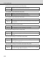
(5) [Upload]
Select the upload operation. If [Enable] is selected, upload is performed every time a motion
detection event occurs. To use this function, the [General Upload] sub-menu and [HTTP
Upload] or [FTP Upload] sub-menu must also be set from the [Upload] menu.
(6) [E-mail Notification]
Select the e-mail notification operation to be performed. If [Enable] is selected, e-mail
notification is performed every time a motion detection event occurs. To use this function, the
[E-mail Notification] sub-menu must also be set from the [Upload] menu.
(7) [Audio Playback at ON Event]
Select the audio playback operation to be performed upon an ON event. If [Enable] is
selected, the sound specified under [Sound Clip] will be played when the mode changes to
[Detected] (ON event).
(8) [Audio Playback at OFF Event]
Select the audio playback operation to be performed upon an OFF event. If [Enable] is
selected, the sound specified under [Sound Clip] will be played when the mode changes to
[Detected] (OFF event).
(9) [Sound Clip]
Select the audio to be played. For registration of sound clips, see "Sound Clip Upload" (
P.
1-39).
(10) [Volume]
Set the sound clip volume as an integer between 1 and 100. The greater the value, the larger
the volume.
(11) [Automatic Tracking at ON Event]
Select the automatic tracking operation. If [Enable] is selected, the camera will automatically
start shaking its head upon entering the [Detected] mode (ON event).
(12) [Maximum Tracking Time (sec.)]
Set the time during which automatic tracking is continued between 1 and 300 seconds.
Note
z The motion detection function cannot be interlocked with external device output. However,
interlocking is possible if the optional recording software RM-64/RM-25/RM-9 is used.
z For the notes on use of motion detection, see "Notes on Use of Motion Detection, Tracking,
Stream for Recording, Image Stabilizer and Bundled Recording Software RM-Lite". (
Guide)
1-36
Start
Setting the Image Buffer, Motion Detection, Audio Playback and Interval Timer (Event)
External Device Input
1
Detailed Settings
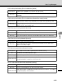
(1) [External Device Input Event]
Select whether to [Enable] or [Disable] external device input events.
(2) [ON Event Operation]
Select the operation to be performed upon an ON event. If [Enable] is selected, (4) "Preset,"
(5) "Upload," and (6) "E-mail Notification" are displayed. When an ON input is received from
an external device (ON event), the processes set in (4), (5) and (6) are performed.
(3) [OFF Event Operation]
Select the operation to be performed upon an OFF event. If [Enable] is selected, (4) "Preset,"
(5) "Upload," and (6) "E-mail Notification" are displayed. When an OFF input is received from
an external device (OFF event), the processes set in (4), (5) and (6) are performed.
(4) [Preset]
Select the preset position. If you want to operate the camera according to events notified from
an external device, set an appropriate preset position using Preset Setting Tool of VBAdmin
Tools (
P. 2-22), and then select the corresponding preset between [Preset 1] and [Preset
20]. If the camera need not be operated, select [None].
(5) [Upload]
Select the upload operation. If [Enable] is selected, upload is performed when an event is
input from an external device. To use this function, the [General Upload] sub-menu and
[HTTP Upload] or [FTP Upload] sub-menu must also be set from the [Upload] menu.
(6) [E-mail Notification]
Select the e-mail notification operation to be performed. If [Enable] is selected, e-mail
notification is performed when an event is input from an external device, provided that
[Enable] is selected. To use this function, the [E-mail Notification] sub-menu must also be
set from the [Upload] menu.
1-37
Setting the Image Buffer, Motion Detection, Audio Playback and Interval Timer (Event)
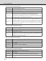
(7) [Audio Playback at ON Event]
Select the audio playback operation to be performed upon an ON event. If [Enable] is
selected, the sound specified in [Sound Clip] is played when an ON event is input from an
external device.
(8) [Audio Playback at OFF Event]
Select the audio playback operation to be performed upon an OFF event. If [Enable] is
selected, the sound specified in [Sound Clip] is played when the event input from an external
device turns OFF.
(9) [Sound Clip]
Select the audio to be played. For registration of sound clips, see "Sound Clip Upload" (
P.
1-39).
(10) [Volume]
Set the sound clip volume as an integer between 1 and 100. The greater the value, the larger
the volume.
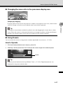
Interval Timer
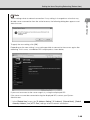
(1) [Interval Timer Event]
Select the time event setting from [Enable] or [Disable]. If you select [Enable], (2) Interval of
the Timer, (3)Upload and (4) E-mail Notification appear.
(2) [Interval of the Timer]
Select a desired timer interval from the pull-down menu in a range of [1 sec.] to [24 hours].
(3) [Upload]
Select the upload operation. If [Enable] is selected, upload is performed at the specified
intervals. To use this function, the [Upload] menu must also be set.
(4) [E-mail Notification]
Select the e-mail notification operation to be performed. If [Enable] is selected, e-mail
notification is performed at the specified intervals. To use this function, the [E-mail Notification]
sub-menu must also be set from the [Upload] menu.
1-38
Setting the Image Buffer, Motion Detection, Audio Playback and Interval Timer (Event)
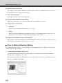
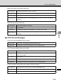
Sound Clip Upload
1
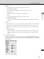
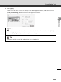
Specify the audio file you want to register as the sound clip, and then click the [Add] button.
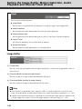
(2) [Sound Clip Name]
Set the name of the audio file to be registered as a sound playback (using up to 15
characters). To delete a registered sound, click [Delete] next to the name of the playback
sound you want to delete.
Tip
You can set only audio files whose playback time is not longer than 20 seconds and file type
is ".wav" (µ-law PCM 8 bits, sampling frequency 8000 Hz, monaural).
1-39
Detailed Settings
(1) [Browse File]
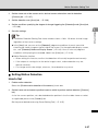
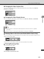
Setting User Access Privileges (Access Control)
You can set the following items.
z Authorized User Account
Register users who can access this camera.
z User Authority
Set the privileges of authorized users and guest users.
z Host Access Restriction
Specify the hosts from which access is permit and restricted.
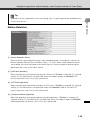
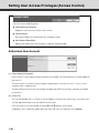
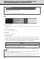
Authorized User Account
(1) [User Name], [Password]
Enter the user name and password and then click [Add]. The authorized user will be added to
the user list.
The user name can consist of up to eight (single-byte) characters of A to Z, a to z, 0 to 9, (hyphen) and - (underscore).
The password can consist of up to eight (single-byte) ASCII characters (space or printable
characters).
(2) [User List]
A list of authorized users is shown. User privileges can be set for these users. Up to 50 users
can be registered other than the Administrator (root).
Also, the user list can be sorted using the
and
buttons on the right.
To delete a user, select the applicable user from the user list and then click [Delete].
1-40
Setting User Access Privileges (Access Control)
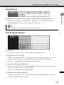
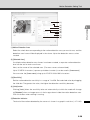
User Authority
1
Detailed Settings
[Privileged Camera Control], [Camera Control], [Image Distribution], [Audio Distribution]
Set the user privileges of authorized users and guest users. Select the check boxes
corresponding to the items you want to permit for each user.
Tip
Authorized users can have higher privileges than guest users.
Host Access Restriction
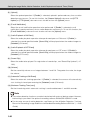
(1) [Host List]
A list of hosts from which access is permitted and restricted is shown.
(2) [Apply the list to HTTP Server]
If [Yes] is selected, the host list is applied to HTTP server access. Not only access from
various viewers, but access to the top page and setting pages is also limited.
The list is also applied when distributing image and audio.
(3) [Apply the list to Image Transmission]
If you select [Yes], the host list is applied when the image transmission function is used.
Access from various viewers can be restricted.
The list is also applied when distributing audio.
(4) [Apply the list to Audio Transmission]
If [Yes] is selected, the host list is applied when the audio distribution function is used.
Utilization of audio can be restricted.
1-41
Setting User Access Privileges (Access Control)
Note
z If no host list is available, access is permitted to all hosts.
z If a host list is given that indicates prohibition of all accesses, the host restriction function is
disabled and access is permitted to all hosts.
z To prohibit access via a proxy server in HTTP connection, a proxy server address must be
set.
z If Host Access Restriction is set wrongly, access to the setting pages itself may be
prohibited, in which case restoring the factory settings will become the only means for
recovery.
z If host access control is implemented, this camera cannot be accessed by IPv6.
z If the [Host List] or [Apply the list to HTTP Server] setting is changed, the camera may
become no longer accessible from the active browser. Check beforehand the precautions
explained in "Notes" in "Setting the Items Requiring Rebooting (Reboot Item)" (
P. 1-49).
Tip
The Host Access Restriction function restricts the hosts on which the viewer and other client
applications are running, where access is restricted using a list containing one or more
entries in the following format.
Listing Format
[!] addr [ -addr2 ]
z "addr" conforms to the standard IP address format.
z The addresses "addr" and "addr2" give the IP address range, and if IP address A is
between addr and addr2, A is included in the range of addr to addr2. It is possible to
omit addr2, in which case the value of addr2 becomes the same as that of addr.
z If the entry starts with "!," access is prohibited. If "!" does not precede the entry,
access is permitted.
z If a given host address corresponds to multiple entries, whether access is permitted
or prohibited is determined by the setting of the first applicable entry after the
beginning of the host list. Accordingly, take note that in Examples 3 to 5 below, an
entry of permitted address must be specified in an entry of prohibited address.
z Redundant and conflicting entries in the list are automatically deleted from the list.
z If the host address does not belong to any entry, access is permitted.
1-42
Setting User Access Privileges (Access Control)
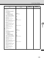
Example of description
Example 1. Prohibit access from a given access
1
!172.20.0.10
Example 2. Prohibit access from hosts in a given range
!172.20.0.0-172.20.0.20
Access from the hosts whose address is in a range of 172.20.0.0 to 172.20.0.20 is prohibited.
Example 3. Permit access from hosts in a given range and prohibit access from all other
hosts
172.20.0.10-172.20.0.12
!0.0.0.0-255.255.255.0
Access is permitted only from the hosts whose address is in a range of 172.20.0.10 to
172.20.0.12.
Example 4. Prohibit access from hosts in a given range, but permit access from hosts at
certain addresses within that range
172.20.0.10
!172.20.0.0-172.20.0.20
Access from the hosts whose address is in a range of 172.20.0.0 to 172.20.0.20 is
prohibited, but access is permitted only from the host whose address is 172.20.0.10.
Example 5. Prohibit access from hosts in a given range, but permit access from hosts in a
given range within that range
172.20.0.10-172.20.0.15
!172.20.0.0-172.20.0.20
Access from the hosts whose address is in a range of 172.20.0.0 to 172.20.0.20 is
prohibited, but access is permitted from the hosts whose address is in a range of
172.20.0.10 to 172.20.0.15.
1-43
Detailed Settings
Access from the host whose address is 172.20.0.10 is prohibited.
IPsec Settings (IPsec)
You can set the following items.
z Various settings can be specified for up to five communicating devices.
IPsec Set
IPsec Sets 1 to 5 are available, where IPsec settings for each communication using each IPsec
Set.
(1) [IPsec]
Select [Manual] if IPsec will be used. Select [Disable] if IPsec will not be used.
(2) [IPsec Mode]
Select [Tunnel Mode] or [Transport Mode] as the IPsec operation mode.
(3) [Destination Address (IPv4/IPv6)]
Enter the IP address of the connection destination.
(4) [Source Address (IPv4/IPv6)]
Enter the IP address of the sender.
(5) [Security Protocol]
Select [ESP], [AH] or [ESP and AH] as the IPsec protocol to be used.
If [ESP] is selected, enter only the setting items relating to ESP.
If [AH] is selected, enter only the setting items relating to AH.
If [ESP and AH] is selected, enter all setting items.
1-44
IPsec Settings (IPsec)
(6) [Security Gateway Address (IPv4/IPv6)]
If the IPsec operation mode was set to [Tunnel Mode] in (2), set the IP address of the security
gateway.
1
This setting is required only when the IPsec operation mode was set to [Tunnel Mode] in (2).
Enter a desired prefix length for connection destination in a range of 0 to 128.
If IPv4 is used, enter a desired length in a range of 0 to 32.
If [ESP] or [ESP and AH] was set under [Security Protocol] in (5), the following items must be
set.
(8) [SA ESP Encryption Algorithm]
Select [AES], [3DES], [DES] or [NULL] as the ESP encryption algorithm according to the
encryption algorithm supported by the device to connect to.
Normally [AES] or [3DES] is recommended.
(9) [SA ESP Authentication Algorithm]
Select [HMAC_SHA1_96], [HMAC_MD5_96] or [No Authentication] as the ESP authentication
algorithm according to the authentication algorithm supported by the device to connect to.
If [ESP] is used alone, [No Authentication] cannot be selected.
1-45
Detailed Settings
(7) [Destination Prefix Length]
IPsec Settings (IPsec)
(10) [SA ESP Encryption key (outbound)]
Set the SA encryption key for outbound. If [AES], [3DES] or [DES] was selected in (8), set a
128-bit, 192-bit or 64-bit hexadecimal, respectively. This item need not be set if [NULL] was
selected.
(11) [SA ESP Authentication key (outbound)]
Set the SA authentication key for outbound. If [HMAC_SHA1_96] or [HMAC_MD5_96] was set in
(9), set a 160-bit or 128-bit hexadecimal, respectively. This item need not be set if [No
Authentication] was selected.
(12) [SA ESP SPI (outbound)]
Set the SA SPI value for outbound. Set a desired value in a range of 256 to 4294967295.
(13) [SA ESP Encryption key (inbound)]
Set the SA encryption key for inbound. If [AES], [3DES] or [DES] was selected in (8), set a
128-bit, 192-bit or 64-bit hexadecimal, respectively. This item need not be set if [NULL] was
selected.
(14) [SA ESP Authentication key (inbound)]
Set the SA authentication key for inbound. If [HMAC_SHA1_96] or [HMAC_MD5_96] was set
in (9), set a 160-bit or 128-bit hexadecimal, respectively. This item need not be set if [No
Authentication] was selected.
(15) [SA ESP SPI (inbound)]
Set the SA SPI value for inbound. Set a desired value in a range of 256 to 4294967295. Since
this setting is used as an ID for identifying the SA, be careful not to specify an inbound SPI
whose value is already used as the SPI for another ESP.
1-46
IPsec Settings (IPsec)
If [AH] or [ESP and AH] was set under [Security Protocol] in (5), the following items must be
set.
1
Detailed Settings
(16) [SA AH Authentication Algorithm]
Select [HMAC_SHA1_96] or [HMAC_MD5_96] as the AH authentication algorithm according
to the authentication algorithm supported by the device to connect to.
(17) [SA AH Authentication key (outbound)]
Set the SA authentication key for outbound. If [HMAC_SHA1_96] or [HMAC_MD5_96] was set in
(16), set a 160-bit or 128-bit hexadecimal, respectively.
(18) [SA AH SPI (outbound)]
Set the SA SPI value for outbound. Set a desired value in a range of 256 to 4294967295.
(19) [SA AH Authentication key (inbound)]
Set the SA authentication key for inbound. If [HMAC_SHA1_96] or [HMAC_MD5_96] was set in
(16), set a 160-bit or 128-bit hexadecimal, respectively.
(20) [SA AH SPI (inbound)]
Set the SA SPI value for inbound. Set a desired value in a range of 256 to 4294967295. Since
this setting is used as an ID for identifying the SA, be careful not to specify an inbound SPI
whose value is already used as the SPI for another ESP.
Note
z To use this camera using IPsec, the communicating destinations and network must be set
beforehand. For these settings, contact your System Administrator.
z If you change any setting from the [IPsec] menu, the active browser may become unable to
connect to the camera. Check beforehand the precautions explained in "Notes" in "Setting
the Items Requiring Rebooting (Reboot Item)" (
P. 1-49).
1-47
Setting the Items Requiring Rebooting (Reboot Item)
The following items that require rebooting, if changed, are gathered here.
z LAN, IPv6, Installation Conditions, MPEG-4, HTTP Server
(1) [LAN]
IP address and other settings required for LAN Connection (
P. 1-8)
(2) [IPv6]
Settings relating to use of IPv6 (
P. 1-9)
(3) [Installation Conditions]
Settings relating to camera installation conditions (
P. 1-20)
(4) [MPEG-4]
Settings relating to video size and frame rate in MPEG-4 (
(5) [HTTP Server]
HTTP port number settings (
1-48
P. 1-33)
P. 1-23)
Setting the Items Requiring Rebooting (Reboot Item)
Note
These settings relate to network connection. If any setting is changed to a value that may
disable camera connection from the active browser, the following dialog box appears and
1
Detailed Settings
alerts the user.
To apply the new setting, click [OK].
Depending on the new setting, it may not be possible to connect to the camera again after
rebooting. In this case, a candidate URI is displayed as shown below,
If you want to connect to the camera again, try using the displayed URI.
If the camera cannot be connected using the displayed URI, contact your System
Administrator.
* In the [Reboot Item] menu, the [IP Address Setting], [IP Address], [Subnet Mask], [Default
Gateway Address] and [HTTP Port] settings relate to network connection.
1-49
Viewing Event Logs and Current Settings, and
Performing Maintenance (Maintenance)
The following items can be used here.
z Tool
Display and initialize the settings of the camera.
Tool
(1) [View Log Events]
Historical data of the camera such as operations and connections with various viewers, etc.,
is shown.
(2) [View Current Settings]
A list of current settings is shown.
(3) [Reboot]
The camera is rebooted.
(4) [Restore Settings]
All setting items of this camera, except for the Administrator password, network settings (IP
address setting, IP address, subnet mask, default gateway), date & time, time zone, LAN
interface, maximum packet size and IPv6, are reset to their factory settings by discarding the
values set by the user. Clicking this button reboots the camera automatically.
Note
While [Restore Settings] is in progress, never turn off the camera. If the power is
turned off, the camera may not reboot correctly.
Tip
z It is recommended that you write down the current settings before restoring the factory
settings using [Restore Settings] (
P. 5-20).
z Although the camera can also be reset to the initial state using the reset switch, take note
that this initializes all settings of the camera other than date and time (
1-50
P. 5-21).
VBAdmin Tools
How to set the camera using VBAdmin Tools is explained. You can
create panorama images, set view restrictions, set presets, set
motion detection, view logs, and launch Admin Viewer. Set each
item after specifying the necessary detailed settings according to
Chapter 1.
Overview of VBAdmin Tools
VBAdmin Tools consists of multiple applications for [Panorama Creation Tool], [View Restriction
Setting Tool], [Preset Setting Tool], [Motion Detection Setting Tool], [Log Viewer] and [Admin
Viewer]. You can remotely set the camera, view privileged images, check the operating condition,
acquire logs, and perform other operations with ease.
VBAdmin Tools (P. 2-6)
This is the main panel for VBAdmin Tools. You can start each tool from this panel. First, install
VBAdmin Tools. See "Install the Necessary Software" ( Start Guide).
Panorama Creation Tool (P. 2-9)
A panorama image capture/creation tool that displays the entire area that can be captured by this
camera. When a panorama image is captured and registered, it is displayed in the panorama
display area of VB-C60 Viewer. When setting view restrictions and presets, you can see at a
glance which part of the entire area is occupied by the set area.
2-2
Overview of VBAdmin Tools
View Restriction Setting Tool (P. 2-14)
A tool that lets you visually set view restrictions. You can set the desired range with the mouse by
referring to the preview in the panorama mode.
VBAdmin Tools
Preset Setting Tool (P. 2-22)
A tool that lets you visually set presets and the home position. You can specify the desired setting
with the mouse by referring to the preview in the panorama mode. You can also set [Preset Tour]
whereby the camera tours and monitors multiple presets.
2-3
Overview of VBAdmin Tools
Motion Detection Setting Tool (P. 2-34)
This tool is used to set the motion detection function that performs upload, notifies the viewer,
records a log, etc., if a change has occurred in the captured image due to movement of a
subject. You can set the position and size of the motion detection area, detection judgment
conditions, etc., while checking the image on the camera.
Log Viewer (P. 2-45)
This viewer shows the logs of operating conditions output to the camera.
2-4
Overview of VBAdmin Tools
Admin Viewer (P. 3-6)
This viewer is used by the camera's Administrator. It provides privileged functions not available in
VB Viewer, such as camera control, exposure, white balance and external device output.
VBAdmin Tools
Note
On the control panel of Windows, the decimal point in a value is always indicated by "."
regardless of the settings of "Region and Language Options." Also, the date is displayed in
the "yyyy/mm/dd" or "mm/dd" format, while the time is displayed in the "hh:mm:ss" format.
* y, m, d, h, m and s indicate year, month, day, time, minute and second, respectively.
2-5
Launching VBAdmin Tools
How to Launch
1. Double-click the [VBAdmin Tools] icon on the desktop, or select [WebView Livescope]
[VBAdmin Tools] from [Programs] in the [Start] menu.
Starting from the Desktop Icon
Or starting from the [Start] menu
2. The dialog box for specifying the camera to connect to appears.
To use VBAdmin Tools, you must connect to the camera first. Enter each item and then click
[OK].
(1)
(2)
(3)
(4)
(5)
(6)
(7)
(1)Host name (
P. 1-8, P. 1-10)
Specify the IP address or host name of the camera.
(2)User name
Enter the Administrator account "root" set for the camera.
(3)Password (
P. 1-7)
Enter the Administrator password (the factory setting is "VB-C60" for both VB-C60 and
VB-C60B).
(4)HTTP port (
P. 1-33)
The default is "80".
(5)Setting page URI
The Setting page URI set for this camera is fixed to "admin" and cannot be changed.
2-6
Launching VBAdmin Tools
(6)Proxy
* For the proxy settings, check with your Network Administrator.
• [Use HTTP proxy server]
Select this check box to connect to the camera via a proxy server.
• [Host name]
Specify the host name or IP address of the proxy server.
VBAdmin Tools
• [Port]
Enter the port number of the proxy server (default = "8080").
• [Load proxy information]
Click this button to automatically import the proxy server information set by Internet
Explorer.
(7)FTP
Not used with this camera. This function can be used with earlier cameras than VB-C50i.
To use Panorama Creation Tool and Log Viewer of VBAdmin Tools, the camera must
establish an FTP connection first. You can select PASV or PORT as the FTP connection
mode.
• [Use PASV mode]
Select this check box if you want to use the PASV mode. Normally the PASV mode
should be used. If this check box is cleared, connection will be made in the PORT
mode.
3. VBAdmin Tools launches.
You can click the button for each of the six tools to launch [Panorama Creation Tool], [View
Restriction Setting Tool], [Preset Setting Tool], [Motion Detection Setting Tool], [Log Viewer] or
[Admin Viewer].
2-7
Launching VBAdmin Tools
If the connection has been cut off, select [Connect] from [File] in the menu bar to open the
[Connection settings] dialog box.
Note
Notes on Use with Windows Vista/XP
If the [Windows Security Alert] dialog box appears, click [Unblock].
Once this button is clicked, this warning dialog box will no longer appear.
Note
If connection is made by entering the IPv6 address, Admin Viewer cannot be used on Internet
Explorer 6.
Tip
z [Panorama Creation Tool], [View Restriction Setting Tool], [Preset Setting Tool] and [Motion
Detection Setting Tool] cannot be launched simultaneously. [Log Viewer] and [Admin
Viewer] can be launched simultaneously.
z If other Canon network camera is connected, the available tools will change.
2-8
Panorama Creation Tool
A panorama image capture/creation tool that displays the entire area that can be captured by this
camera. When panning, tilting or zooming the camera or setting a preset using VB-C60 Viewer,
you can see at a glance which part of the entire area is occupied by the set area.
VBAdmin Tools
Capturing/Creating Panorama
Images with Panorama Creation
Tool and Registering Them to
This Camera
Admin Viewer
Preset Setting Tool
You can see at a glance
which part of the entire area
is occupied by the set area.
2-9
Panorama Creation Tool
Display Screens of Panorama Creation Tool
(2)
(1)
(3)
(4)
(8)
(7)
(6)
(5)
(1) [Show registered panorama image] button
Show the panorama images registered in the camera.
(2) [Register panorama image] button
Register the currently displayed panorama image in the camera.
(3) Camera Model/Date Display
Shows the model of the currently connected camera, and if there is a panorama image, the
date it was captured.
(4) Panorama Image Display
Display the captured panorama image.
(5) [Capture] button
Capture a panorama image.
(6) [Remove image] button
Delete the captured panorama image.
(7) [Position of AE lock]
Switch the AE lock position between [Center] and [Current position]. AE lock is a function that
lets you capture images based on the brightness of the set position.
(8) [Indoor dome housing (VB-RD51S)]
When this check box is selected, the area concealed by the optionalIndoor Dome Housing
(VB-RD51S-C/S) is not captured.
2-10
Panorama Creation Tool
Capturing Panorama Images
How to Capture
1. Click the [Capture] button to start capturing an image.
If necessary, switch the AE lock position.
To stop the capture in the middle, click the [Stop] button.
2. If you are happy with the captured image, click the [OK] button.
To recapture an image, click the [Recapture] button.
Also, double-clicking each part of the displayed grid lets you recapture the applicable part
only.
To discard the captured image, click the [Cancel] button.
2-11
VBAdmin Tools
If the optional Indoor Dome Housing is used, select the [Indoor dome housing (VB-RD51S)]
check box.
Panorama Creation Tool
Tip
While a panorama image is being captured, the image stabilizer function is temporarily
disabled.
Registering/Deleting Panorama Images
When the panorama image has been captured, send it to this camera. The image will be reflected
upon registration.
How to Register
Click the [Register panorama image] button.
The panorama image is registered.
How to Delete
To delete the panorama image you have captured, click the [Remove image] button and then click
the [Register panorama image] button.
The panorama image saved in the camera is deleted.
2-12
Panorama Creation Tool
Tip
When the panorama image has been registered, the camera is automatically rebooted and its
connection with VBAdmin Tools is terminated. After the camera is rebooted, a dialog box
appears asking if you want to connect the camera again. Clicking the [OK] button reconnects
the camera.
VBAdmin Tools
Reconnecting
Reconnects the camera if it is disconnected.
How to Reconnect
Select [Reconnect] from [File] in the menu bar.
Opening Panorama Images from Image Files/Saving as
Image Files
You can open image files as panorama images or save captured panorama images as image
files. Only the JPEG image files created in Panorama Creation Tool can be handled.
How to Open from Image Files
Select [Open] from [File] in the menu bar. In the displayed dialog box, select the image file you
want to use.
How to Save
Select [Save] from [File] in the menu bar. In the displayed dialog box, select the folder you want to
save and enter the file name.
2-13
View Restriction Setting Tool
View Restriction Setting Tool is a tool that limits the range that can be captured by the camera. If
view restrictions have been set, you can limit the displayable capture range using VB-C60 Viewer.
To limit zoom or a certain field of view
when publishing live video use View
Restriction Setting Tool to easily set the
view restrictions.
Applying View Restriction Setting
Restrictions set by View Restriction Setting Tool are applied in the following cases.
• When Admin Viewer was accessed as an authorized user
• Accessing VB Viewer
2-14
View Restriction Setting Tool
Display Screens of View Restriction Setting Tool
(1)(2)
(3)
VBAdmin Tools
(4)
(5)
(3)-1
(3)-2
(3)-3
(6)
(7)
(10)
(9)
(8)
(1) [Load view restriction settings] button
Load the current view restriction settings of the camera.
(2) [Save view restriction settings] button
Save the view restriction settings set/applied using this tool, in the camera.
If view restrictions have been set, be sure to save the settings in the camera using the [Save
view restriction settings] button.
(3) Panorama Preview
The panorama images registered in the camera. are displayed. Also, a view restriction
preview frame recreating the view restriction settings is displayed, where you can drag the
frame to change its shape and reflect the new frame in the view restriction settings.
● View restriction preview frame
(3)-1 Pan/tilt preview frame (red frame) ......................Range of field of view defined by top/
bottom/left/right edges
(3)-2 Wide-angle preview frame (green frame) ..........Wide-angle restriction setting
(restriction of capture frame)
(3)-3 Telescopic preview frame (yellow frame) ...........Telescopic restriction setting
(restriction of maximum zoom ratio)
2-15
View Restriction Setting Tool
(4) [Model]
The model of the connected camera is displayed.
(5) [Apply the view restriction]
To use view restrictions, select this check box.
(6) View restriction setting entry boxes and [Get value] button
You can enter a value in each view restriction setting entry box to change the applicable
setting.
You can load the current camera angle into each setting by clicking the [Get value] button.
● View restriction settings
[Upper limit] ...Top limit of the view restriction. Use the [Get value] button to acquire the top
edge value of the viewing angle.
[Lower limit]....Bottom limit of the view restriction. Use the [Get value] button to acquire the
bottom edge value of the viewing angle.
[Left limit] .......Left limit of the view restriction. Use the [Get value] button to acquire the left
edge value of the viewing angle.
[Right limit] .....Right limit of the view restriction. Use the [Get value] button to acquire the
right edge value of the viewing angle.
[Telephoto] .....Telescopic limit of the view restriction. Use the [Get value] button to acquire
the zoom ratio of the viewing angle.
[Wide-angle] ..Wide angle limit of the view restriction. Use the [Get value] button to acquire
the zoom ratio of the viewing angle.
(7) [Apply] button
Apply the current view restriction settings to this camera. At this point, the settings are not yet
saved in the camera. Be sure to click [Save view restriction settings].
(8) [Preview] button
Reflect the settings in the view restriction setting entry boxes in the view restriction preview
frame.
(9) [Admin Viewer] button
Launches Admin Viewer.
(10) Status List
The results of operations performed with this tool are displayed.
Warning messages are shown in blue, while error messages are shown in red.
2-16
View Restriction Setting Tool
Note
z Clicking the [Apply] button alone does not save the edited results in the camera. To make
the edited results effective, click the [Save view restriction settings] button.
z If connection is made by entering the IPv6 address, Admin Viewer cannot be used on
Internet Explorer 6.
You can set view restrictions by entering values in the view restriction setting entry boxes, or by
changing the current settings in the view restriction preview frame or from the camera angle in
Admin Viewer. Select appropriate settings according to the environment in which the camera is
operated or based on your preference.
Changing Settings from View Restriction Preview Frame
Use the preview frame on the panorama image to set view restrictions.
How to Set
1. Select the [Apply the view restriction] check box.
2. Drag to change the Pan/tilt preview frame (red frame), Telescopic preview frame (yellow frame)
or Wide-angle preview frame (green frame) displayed on the panorama image to set view
restrictions.
When the telescopic/wide-angle preview frames are enlarged/shrunk, the aspect ratio
remains the same.
At this time, you can also enter view restrictions by entering values in the view restriction
setting entry boxes.
2-17
VBAdmin Tools
Setting View Restrictions
View Restriction Setting Tool
3. Click [Apply].
Confirm on the status list that the settings have been applied correctly, and then click the
[Save view restriction settings] button to save the settings in the camera.
Changing Settings from Camera Angle in Admin Viewer
Launch Admin Viewer and set each view restriction while checking the position on the image.
How to Set
1. Select the [Apply the view restriction] check box.
2. Click the [Admin Viewer] button to launch Admin Viewer.
User authentication is required to access Admin Viewer (
P. xiv).
3. Click "Obtain/release Camera Control" button on Admin Viewer to obtain the control privileges
of the camera.
"Obtain/release Camera Control" button
2-18
View Restriction Setting Tool
4. Operate the camera to adjust the top edge, bottom edge, left edge, right edge, telescopic or
wide angle to desired positions, and then click each [Get value] button.
The loaded view restriction can be checked in the view restriction setting entry box or view
restriction preview frame.
VBAdmin Tools
5. Click [Apply].
Check the status list to make sure the settings have been applied correctly, and then click the
[Save view restriction settings] button to save the settings in the camera.
Note
z If you have changed the setting for the camera mounting method, recapture the panorama
image and register it again.
z The panorama preview may be slightly different from the actual image. After view
restrictions have been set, be sure to confirm with VB Viewer that the view restrictions have
been reflected correctly.
z Confirm the settings using VB Viewer. (View restrictions are not applied to Admin Viewer.)
z If the image stabilizer setting is changed after view restrictions have been set, the set view
restrictions no longer agree with the view restrictions applied during operation (
P. 3-22).
z If the image stabilizer or electronic zoom setting has been changed, check the view
restriction settings again.
2-19
View Restriction Setting Tool
Tip
z Even when view restrictions are set, an area outside the view restriction may still appear
momentarily when the camera is controlled near the boundary of the view restriction.
z To cancel the view restrictions, clear the [Apply the view restriction] check box and then
click the [Apply] button, followed by the [Save view restriction settings] button.
z If the setting fields are cleared while the [Apply the view restriction] check box is selected,
the maximum view restriction will be set.
Tilt controllable area
maximum up/down capture area
z The controllable range and range that can be captured are as follows.
Maximum wide-angle viewing angle
Pan controllable area
Maximum left/right captured area
2-20
View Restriction Setting Tool
z The pan and tilt ranges vary depending on the zoom ratio (view angle).
When the view restriction is
set, the camera operation
angle is automatically
restricted.
When a wide-angle is used
without changing the camera
operation angle, the view
restriction is violated, and
therefore the operation angle
is automatically narrowed.
VBAdmin Tools
Restricted view angle
Camera operation angle
Camera
Captured image angle
z If the view restriction will be exceeded as a result of controlling the zoom toward the wideangle side, the camera will first pan and tilt to a position where the maximum wide-angle
zoom will be within the viewing restriction area. Wide-angle zoom control will then be
enabled within the view restriction area.
First, the center of the
maximum wide-angle
zoom is panned and tilted.
Captured image
After panning and tilting,
wide-angle zoom control is
enabled within the view restriction.
Restricted view angle
Zoom out
Zoom out
z Reducing the view restriction may also reduce the zoom range.
2-21
Preset Setting Tool
A tool that lets you set presets and the home position in a more visual, easy manner. You can
specify a desired setting with the mouse by referring to the preview in the panorama mode. You
can also set [Preset Tour] whereby the camera goes around and monitors multiple presets.
Set preset tour after the presets
Preset Setting Tool
have been set.
Reflecting in VB-C60 Viewer
Executing preset tour
2-22
Preset Setting Tool
Display Screens of Preset Setting Tool
The display screens of Preset Setting Tool are divided into "Preset Setting Area" and "Preset Tour
Setting Area." In the "Preset Setting Area," up to 20 presets and the home position are set while
referring to the panorama preview. In the "Preset Tour Setting Area," "Preset Tour" is set whereby
the camera goes around and monitors multiple presets.
VBAdmin Tools
The following explains the display screen "Preset Setting Area."
For the "Preset Tour Setting Area," see "Preset Tour" (
P. 2-29).
Display Screen of "Preset Setting Area"
(1)(2)
(4) (5)
(3)
(6)
(7)
Preset Setting
(8)
Area
(9)
Preset Tour
Setting Area
(
P. 2-29)
(13)
(12)
(11)
(10)
(1) [Load preset settings] button
Clicking this button loads the current preset settings of the camera.
(2) [Save preset settings] button
Save in the camera the preset information values that have been set/applied using this tool.
If a preset has been set, be sure to save it with the [Save preset settings] button.
2-23
Preset Setting Tool
(3) Panorama Preview
The panorama images registered in the camera. are displayed. Also, the preset preview
frame (yellow) recreating the preset settings is displayed, where you can drag to resize/move
the frame and reflect the new frame in the preset settings.
(4) [Preset]
Select the preset or home position you want to set.
(5) [Not shown in viewers]
If presets are used from VB-C60 Viewer, clear this check box. If [Home position] was selected
in [Preset], this setting is grayed out (disabled).
(6) Preset name
You can enter a preset name. You can set a name in Japanese or single-byte alphanumerics. If
[Home position] was selected in [Preset], this setting is grayed out (disabled).
If names are entered in both Japanese and single-byte alphanumerics, the Japanese name is
given priority and displayed in the preset of VB-C60 Viewer. Be sure to enter a preset name in
single-byte alphanumerics.
Up to 15 ASCII characters (space or printable characters) can be used in the Preset name.
(7) [Model]
The model of the connected camera is displayed.
(8) Camera Parameter
Enter the center angle of the desired angle in [Pan] and [Tilt]. In [Zoom], enter the view angle.
z Camera angle
Pan .............. Set the pan position of the camera.
Tilt ............... Set the tilt position of the camera.
Zoom ........... Set the viewing angle of the camera.
z Backlight Compensation
Set [BLC] of the camera. Select [OFF] or [ON].
z Focus Mode
Set [Focus mode] of the camera. Select [Auto], [Fixed at infinity] or [Manual] (
P. 3-26).
(9) [Get value] button
Load the camera angle, focus position (in the manual mode) and backlight compensation
settings currently selected in the camera, as camera parameters.
(10) [Apply] button
Apply the current preset and preset tour settings to the camera.
2-24
Preset Setting Tool
(11) [Preview] button
Reflect the settings of camera parameters in the preset preview frame. Also, the camera
angle switches to this preset, and the new angle can be checked in Admin Viewer.
(12) [Admin Viewer] button
Launches Admin Viewer.
Use this button if you want to set a preset while actually checking the image using Admin
Orient the camera to the position you want to set as a preset using Admin Viewer, and then
click the [Get value] button and [Apply] button in this order to set the preset.
(13) Status List
Shows the result of communication between this tool and the camera.
Warning messages are shown in blue, error messages in red.
Note
z Sending the edited results to the camera using the [Apply] button does not save the edited
results in the camera. After confirming the edited results, be sure to click the [Save preset
settings] button to save the settings in the camera.
z If connection is made by entering the IPv6 address, Admin Viewer cannot be used on
Internet Explorer 6.
Setting the Preset
A preset can be set in one of the following two ways. Select appropriate settings according to the
environment in which the camera is operated or based on your preference.
Note
To use presets in VB-C60 Viewer, unselect the [Not shown in viewers] check box.
2-25
VBAdmin Tools
Viewer.
Preset Setting Tool
Changing Settings in Preset Preview Frame
Use the preview frame on the panorama image to set presets.
How to Set
1. Select the preset you want to set from the preset selection box, and then fill the [Preset name]
field.
Be sure to enter the preset name (single-byte alphanumerics).
2. Drag to move/resize the preset preview frame displayed on the panorama image to set the
preset.
Clicking on the image moves the preview frame until the clicked point becomes the center.
At this time, you can also edit the camera parameter values to fine-tune the set position.
3. Click [Apply].
Confirm on the status list that the settings have been applied correctly, and then click the
[Save preset settings] button to save the settings in the camera.
2-26
Preset Setting Tool
Changing Settings from Camera Angle in Admin Viewer
Launch Admin Viewer and set its viewing angle as a preset.
How to Set
1. Select the preset you want to set from the preset selection box, and then fill the [Preset name]
field.
VBAdmin Tools
2. Click the [Admin Viewer] button to launch Admin Viewer.
User authentication is required to access Admin Viewer (
P. xiv).
3. Click "Obtain/release Camera Control" button on Admin Viewer to obtain the control privileges
of the camera.
4. Operate the camera to adjust to a desired position, and then click the [Get value] button.
The loaded values can be checked by the camera parameters or in the preset preview frame.
At this time, you can also edit the camera parameter values to fine-tune the set position.
2-27
Preset Setting Tool
5. Click [Apply].
Check the status list to make sure the settings have been applied correctly, and then click the
[Save preset settings] button to save the settings in the camera.
Note
z The preview based on the panorama preview function may vary slightly from the actual
image. After setting a preset, be sure to confirm with Admin Viewer that the preset has
been reflected correctly.
z To apply the manual focus mode, manually adjust the focus while checking the actual
image using Admin Viewer. After the focus has been adjusted, set the focus using the [Get
value] button. You can save the focus value using the [Save preset settings] button.
z If the image stabilizer setting is changed after a preset has been set, the set viewing angle
will no longer agree with the viewing angle during operation (
P. 3-22). If the image
stabilizer setting has been changed, check the preset settings again.
z If a dome housing is used, be sure to set presets with the dome installed.
z If the camera mounting method has been changed, set presets again.
Tip
z Up to 20 presets can be set.
z Changes to preset settings are not reflected in the connected viewer.
z You can disable presets in VB-C60 Viewer by selecting the [Not shown in viewers] (
P. 2-
24) check box.
z Preset positions cannot be set in the digital zoom area.
z You can also set multiple presets and save them all at once using the [Save preset settings]
button.
2-28
Preset Setting Tool
Preset Tour
Set a preset tour whereby the camera goes around and monitors the multiple presets currently
set.
Display Screen "Preset Tour Setting Area"
(2)
(3)
VBAdmin Tools
(1)
(6)
(7)
(8)
(9)
(4) (5)
(1) Tour schedule list
A list of presets for which preset tour has been set is displayed.
(2) [Add] button
Add to the tour schedule list the preset you have set.
(3) [Up] and [Down] buttons
Select each preset in the list and click the [Up] or [Down] button to change the sequence of
preset tour. In preset tour, the presets are checked one by one from the top.
(4) [Delete] button
Delete the selected preset.
(5) [Preview] button
Reflect the selected preset setting in the preset preview frame. Also, the camera angle
switches to this preset, and the new angle can be checked in Admin Viewer.
(6) Auto preset tour
Select the timing of preset tour from the following options.
[Not used]
Preset tour is not performed.
[For viewers]
Preset tour is performed when a camera is connected via VB-C60 Viewer, etc.
[Always]
Preset tour is always performed.
2-29
Preset Setting Tool
(7) [Speed (PT)]
Set the moving speed of the camera during panning/tilting between 1 and 3. Moving the slide
bar from the left to right increases the value and consequently raises the speed.
(8) [Speed (Z)]
Set the speed of the camera during zoom in a range of 1 to 2. Moving the slide bar from the
left to right increases the value and consequently raises the speed.
(9) [Pause (sec)]
Set the time at which the camera stops at the preset position between 0 and 120 seconds in
5-second units.
Note
If the following warning is displayed, consider changing the settings by referring to the table
below.
Example of Warning Screen
* The touring time on the screen changes depending on the settings.
Clicking Cancel returns the display to the setting screen.
Clicking OK saves the set data.
(If you are using Preset Setting Tool, click [Save] on the setting page.)
2-30
Preset Setting Tool
As a rough guide, the pan/tilt mechanism can withstand 300,000 back-and-forth movements
in full-angle operation *. The total touring time is determined by a combination of moving
speed, moving range and pause duration. Set an appropriate time by referring to the table
below.
Total touring time until preset tours corresponding to 300,000 back-and-forth movements are
completed in the pan direction (rough guide)
Pause
(sec.)
0
10
20
30
Pan Direction Movement Range (degree)
± 50 ± 100 ± 150
11616 11475 11427
17000 14166 13222
22666 17000 15111
28333 19833 17000
Pause
(sec.)
0
10
20
30
(Unit: hour)
Pan Direction Movement Range (degree)
± 50 ± 100 ± 150
5761
5808
5950
7555
8500
11333
9444
17000 11333
22666 14166 11333
(Unit: hour)
Example: Speed (PT): 1, Pause: 30 seconds, Moving range (angle) in pan direction: If ± 50
degrees, 300,000 back-and-forth movements will be completed in 28333 hours.
* Based on our measurement standards
Tip
z Preset tour is not performed while the camera is being controlled with VB-C60 Viewer, etc.
z Preset tour is disabled when options such as RM-64/RM-25/RM-9, bundled RM-Lite, and
Motion Detection Setting Tool are connected to the camera.
2-31
VBAdmin Tools
Setting Speed (PT) to 2
Setting Speed (PT) to 1
Preset Setting Tool
Setting the Preset Tour
How to Set
1. Select the touring method from [Auto preset tour].
Select [For viewers] or [Always].
2. Select from [Preset] in the preset setting area the preset number you want to add to the tour
schedule, and then click the [Add] button.
The preset is registered in the tour schedule list. Up to 20 presets can be registered.
3. Select a preset in the tour schedule list and set the pan/tilt/zoom speeds for each preset using
the [Speed (PT)], [Speed (Z)] and [Pause (sec)] slide bars, as well as the time in seconds
during which the camera remains stationary at the preset position.
Clicking the [Preview] button reflects the selected preset settings in the preset preview frame.
Also, the camera angle switches to this preset, and the new angle can be checked in Admin
Viewer.
2-32
Preset Setting Tool
4. Click [Apply].
Confirm on the status list that the settings have been applied correctly, and then click the
[Save preset settings] button to save the settings in the camera.
VBAdmin Tools
Note
If preset tour is used, do not use the motion detection function. Also note that when [Auto] is
set under [Day/Night], the pause time may become longer.
Tip
The home position cannot be added to the tour schedule list.
2-33
Motion Detection Setting Tool
This tool is used to set the motion detection function that performs upload, notifies the viewer,
records a log, etc., if a change has occurred in the captured image due to movement of a
subject. You can set the position and size of the motion detection area, detection judgment
conditions, etc., while checking the image on the camera.
You can set the Motion Detection
function with ease using Motion
Detection Setting Tool.
The Motion Detection function determines the following items to specify when the camera mode
should change to [Detected] and the specified operations such as event upload should be
performed, upon change in the viewer image inside the motion detection area: (1) [Sensitivity]
indicating the degree of change, (2) [Size] indicating the ratio of the changed area, and (3)
[Duration] indicating how long the change continues.
Note
Notes on Use of This Camera
The Motion Detection function is not suitable in applications where high
reliability is required. If high reliability is always required for monitoring, etc., it is
recommended that you don't use this function. Canon shall assume no liability
for any accident, loss or other undesirable outcomes resulting from operating the
motion detection function.
2-34
Motion Detection Setting Tool
Display Screen of Motion Detection Setting Tool (Live Mode)
(1)(2)
(3)
(4)
(8)
VBAdmin Tools
(9)
(5)
(6)
(7)
(10)
(1) [Load Motion Detection Settings] button
Clicking this button loads the current motion detection settings of the camera.
(2) [Save Motion Detection Settings] button
Clicking this button saves the motion detection setting edited by this tool.
If you have set motion detection, be sure to save the settings using [Save Motion Detection
Settings].
(3) Live mode tab (Live/Record)
• [Live]
Video is displayed and the camera is controlled. The displayed video is also recorded.
• [Video]
You can set motion detection judgment conditions while playing the recorded video. For
the specific screen views and operating procedures, see P. 2-43.
(4) Camera Selection box
The name of the connected camera is shown.
(5) Viewer
Video is displayed and the camera is controlled.
2-35
Motion Detection Setting Tool
(6) Motion detection area frame
The range in which motion detection is performed is shown by a dotted-line frame. You can
drag the mouse to resize/move the frame.
(7) [Start recording] button
Clicking this button starts recording video.
(8) [Enable motion detection of the camera]
Select this check box if you want to enable the motion detection function.
(9) Settings tabs (Camera/Area)
• [Camera]
Set the frame rate and preset position (
P. 2-37).
• [Area]
Select the motion detection area and the sensitivity, size and duration for each area. For
the specific screen views and operating procedures, see P. 2-38.
(10) [Display motion detection status of the camera]
Selecting this check box displays the motion detection status of the camera. You can check if
the settings are enabled on the camera (
P. 2-41).
Flow of Motion Detection Setting
The motion detection function is set according to the procedure below. For details on the setting
method, see each setting page.
1. Launches Motion Detection Setting Tool.
The Motion Detection Setting Tool window appears ("Display Screen of Motion Detection
Setting Tool (Live Mode)" (
P. 2-35)).
Set motion detection in the Settings tab on the right side of the screen. The Settings tab has
two tabs: [Camera] and [Area].
2-36
Motion Detection Setting Tool
2. Set the frame rate of the camera and a desired camera orientation used for detection
([Camera] tab
P. 2-37).
3. Set the detection area ([Area] tab,
P. 2-38)
4. Set the conditions specifying the degree of change triggering the [Detected] mode ([Area] tab,
P. 2-38).
Tip
z The Motion Detection Setting Tool viewer window shows a 160 x 120 black & white image
regardless of the camera settings.
z In the [Area] tab, you can set the [Detected] judgment conditions for each area while
checking the viewer image on the left side of the screen. For the applicable display screen,
etc., see "[Detected] Mode and Display Screen" ( P.2-42). You can also set judgment
conditions while playing the recorded video in the [Live] tab (
P. 2-43).
z Motion Detection function
• When setting this function, confirm that detection will actually be performed correctly.
• If the subject is moving fast or the entire image is dark, motion detection may not
operate correctly.
• If a change occurs due to light, wind, etc., false detection may occur.
Setting Motion Detection
How to Set
1. Enable motion detection.
Select the [Enable motion detection of the camera] check box.
2. Set the frame rate and camera position based on which to perform motion detection ([Camera]
tab).
As for the camera position, set a desired detection position in the live video viewer or select
an applicable preset in the [Camera] tab.
Set the preset beforehand using Preset Setting Tool (
P. 2-25).
2-37
VBAdmin Tools
5. Save the settings.
Motion Detection Setting Tool
(1)
(2)
(1)Setting Frame Rate
When this check box is selected, the camera's frame rate for motion detection can be
changed. Enter a desired rate in a range of fps 0.5 to 30.0.
(2)Enable preset selection
When this check box is selected, you can select the camera position using a preset.
Note
The value set in [Maximum Frame Rate: Image Transmission] (
P. 1-22) must be greater than
the frame rate set by this tool.
Tip
z If the network load is heavy, the specified frame rate may not be achieved.
z By setting a lower frame rate, the video extracted from the captured video will be included
in the scope of motion detection. This way, you can also perform motion detection for slowmoving subjects, etc.
z The frame rate set here is applied only to motion detection.
z Presets outside the view restriction are not shown in the preset list.
3. Set the motion detection area ([Area] tab).
Up to four motion detection areas can be created, where the frame of each area can be
resized/moved by dragging. To resize the frame, drag "" at four corners/on four sides. To
move the frame, drag a point inside the frame. You can also set a separate motion detection
level for each area. This camera lets you set the motion detection level while playing the video
recorded in the [Live] tab (
2-38
P. 2-43).
Motion Detection Setting Tool
(1)
VBAdmin Tools
(2)
(3)
(4)
(5)
(6)
(7)
(8)
(1)Motion Detection Area
Select the check box corresponding to the motion detection area you want to use, and the
detection area frame will be displayed in the viewer. Up to four detection areas can be
created.
(2)[Selected Area]
If multiple motion detection area frames have been created, a separate motion detection
level can be set for each area frame.
Next, set the name of the selected area. (The area name can be omitted.)
Up to 15 ASCII characters (space or printable characters) can be used in [Area name].
You can enter the [Area name] using up to 15 JIS X 0208-1990 characters.
(3)[Sensitivity]
Set the motion detection sensitivity in a range of 1 to 256. Set a desired value by dragging
the slide bar. The greater the value, the higher the detection sensitivity becomes.
(4)[Auto] button
Clicking [Auto] allows the sensitivity to be set automatically at which the mode will change
to [Detected] when a change occurs in the image shown inside the motion detection area.
Click this button when nothing is moving.
(5)Detection Indicator
The level of the motion detected by the camera is shown in a graph in real time (
P. 2-42).
2-39
Motion Detection Setting Tool
(6)[Size]
The camera mode will change to [Detected] if the ratio of the area in which change has
been detected (red or yellow rectangle) to the area of the selected active detection area
frame (frame indicated by blue solid lines) exceeds the value set here (
P. 2-42).
However, the mode will not change to [Detected] even when the set value of [Size] has
been exceeded, if the change has not continued for the duration in seconds set in
[Duration]. Set a desired value between 0 and 100% by dragging the slide bar.
(7)Duration
The camera mode will change to [Detected] if the change occurring in the image inside the
detection area has satisfied the conditions set in (3) [Sensitivity] and (6) [Size] for the
duration set in [Duration].
Normally [Duration] is fixed to "0.2". If the [Detailed Settings] check box is selected,
however, you can set a desired value in a range of 0 to 5 seconds by directly entering a
value or dragging the slide bar.
(8)[Detailed Settings]
When this check box is selected, you can enter [Sensitivity], [Size] and [Duration] values.
If the check box is cleared [Duration (sec.)] is fixed to "0.2".
Tip
z Even when a change has occurred in the image shown inside the viewer's motion detection
area frame, the camera will not recognize it as [Motion] if the [Sensitivity] setting is low.
Even when the sensitivity is raised, the camera mode will not change to [Detected] unless
the part of the area frame that has moved meets the [Size] and [Duration] settings for
motion.
z You can also select the setting area by clicking a desired motion detection area frame in
the viewer. The selected detection area frame is shown by blue solid lines.
z By setting the selected area to [Not selected], you can show the detection statuses for all
motion detection areas at once. Clicking a point in the viewer where no area frame is set
has the same effect.
2-40
Motion Detection Setting Tool
4. Check the motion detection status of the camera.
To check the level of motion detection operation based on the specified settings, select the
[Display motion detection status of the camera] check box. The motion detection status will be
shown by the icons specified below.
If the [Display motion detection status of the camera] check box is selected, the settings
cannot be saved. To save the settings, clear this check box.
VBAdmin Tools
(Detection disabled)
[Detected]
[Not detected]
Note
z If a proxy server is used, the video frame rate may drop depending on the proxy load.
Accordingly, it is recommended that you don't connect the camera via a proxy while this
function is set.
z It is recommended that the motion detection level be set in a condition as close as possible
to the condition in which the camera is actually used.
Tip
z The status of the detection in peak block view and [Display motion detection status of the
camera] in this tool may not match the actual motion detection status of the camera.
z When the motion detection function of the camera is enabled, the video frame rate may
drop compared to when the function is disabled.
z Clicking [Edit] in the menu bar and selecting [Copy sensitivity settings] copies the settings
of [Sensitivity], [Size] and [Duration] for the currently selected area (1 to 4). If a different
area (1 to 4) is subsequently selected and [Paste sensitivity settings] is selected from [Edit]
in the menu bar, the copied settings will be pasted to the selected area.
5. Click [Save motion detection settings] to save the settings.
2-41
Motion Detection Setting Tool
Tip
[Detected] Mode and Display Screen
The area frame in which the camera is
detecting motion is displayed by blue
solid lines in the viewer.
The area in which the camera is detecting
motion at the specified sensitivity is
displayed by a yellow or red rectangle
inside the motion detection area frame.
Yellow rectangle: The camera detected
a motion, but it did not meet the [Size]
or [Duration] setting and thus the mode
has not changed to [Detected].
Red rectangle: The camera detected a
motion, but it met the [Size] or
[Duration] setting and thus the mode
has not changed to [Detected].
If a change occurred in the image, the value
set in [Size] is shown by a vertical bar on the
indicator. The following two indicator colors
are used.
Green: The area of the motion detected
by the camera does not meet [Size].
Yellow: The area of the motion detected
by the camera meets [Size].
Peak block
A red peak block will be displayed when
both the [Size] and [Duration] conditions
are satisfied and the camera mode
changes to [Detected]. Set the motion
detection level while checking when a
peak block is actually displayed at a given
level of motion.
2-42
Motion Detection Setting Tool
(Motion level)
Set value or bigger
Duration
Less than the set value
Duration
Time
Indicator color Green
Yellow
Green
Peak block display (in red)
Not detected
Detected
Not detected
If a motion corresponding to [Size] or greater has remained detected for the specified
duration or longer, the mode changes to [Detected] and a peak block is displayed. Even
when the specified size becomes no longer met in the [Detected] mode where a peak block is
still displayed, the [Detected] mode will be maintained for the specified duration.
Setting the Motion Detection Sensitivity While Checking the Recorded Video
To set the motion detection level at which the camera mode will change to [Detected], you
can adjust the settings while checking the actual motion in the viewer. The camera lets you
set a desired motion detection level while playing the live video recorded in the Live tab (
P. 2-35), so you need not repeat the actual motion in front of the camera.
* If you are using Windows Vista without SP1, recording by Motion Detection Setting Tool
may not be possible.
1. Selecting [Video recording options] from [Tools] in the menu bar opens the Video recording
options dialog box.
Video recording options dialog box
(1)[Maximum recording time]
Set the maximum recording time. Set a desired value in a range of 60 to 300 seconds.
(2)[Self-timer]
Set the time after clicking the Rec. Start button when recording will be started. Set a
desired value in a range of 0 to 30 seconds.
2-43
VBAdmin Tools
Detection status
Motion Detection Setting Tool
2. Adjust the camera position and click the Start recording button in the [Live] tab.
Recording of the video shown in the viewer will start. Record the video needed to adjust
the motion detection level by creating motion in front of the camera.
To stop recording, click the Stop button.
3. Adjust the motion detection sensitivity in the [Area] tab while checking the video in the
[Video] tab.
(1)
(2)
(3)
(4)
(1)List of recorded video
A list of recorded video is shown.
(2)[Delete] button
Clicking this button deletes the video selected from the list of recorded videos.
(3)[Delete all] button
Clicking this button deletes all videos shown in the list of recorded videos.
(4)Control buttons
The available buttons are "Move to Start", "Rewind", "Play", "Fast Forward" and "Move to
End" from the left.
When the [Loop playback] check box is selected, the video is played repeatedly.
2-44
Log Viewer
This viewer lets you view the operating condition log of the camera.
VBAdmin Tools
Tip
z Log Viewer only has a log viewing function and logs cannot be deleted.
z Logs are saved by selecting [Save] from [File] in the menu bar. Logs can be saved in the
text format.
Downloading Log Files
How to Download
Launch Log Viewer from VBAdmin Tools, and the latest log files will be downloaded and
displayed automatically. To download a new log file list, select [Download] from [File] in the menu
bar.
When the list has been downloaded, a dialog box showing the log file list opens. Select the log
file you want to view and click [Download], and the selected log file will be downloaded.
2-45
Log Viewer
Viewing Logs
The log contains the following information.
z
Code
The log code is shown. For the log code, see "List of Log Messages" ( P.5-7).
The log code is shown together with one of three icons corresponding to the applicable level.
If the log has no log code, no icon is shown.
Information
Error level
level
Warning level
z
Date & Time
The date and time at which the log was generated is shown.
z
Message
A message regarding the log is shown.
Saving a Log to a File/Opening a Saved Log
You can save the displayed log to a file or view a log file saved before.
How to Save
Select [Save] from [File] in the menu bar.
2-46
Log Viewer
How to View
Select [Open] from [File] in the menu bar and then select the log file you want to view.
VBAdmin Tools
Copying/Searching Logs
You can copy the displayed log or search logs.
How to Copy
Click to select the log you want to copy, and then select [Copy] from [Edit] in the menu bar.
How to Search
1. Select [Search] from [Edit] in the menu bar.
The Search dialog box appears.
2. Enter a desired character string, and then click [Search].
2-47
Log Viewer
Showing All Logs
How to Display
Select [Show all logs] from [View] in the menu bar.
All event logs are shown, including the logs specified in the log message list (
like when [View Log Events] (
P. 1-50) is selected from [Maintenance]
P. 5-7), just
on the setting
page.
Showing Filtered Logs
You can filter logs by type, code and date & time to show only the necessary information.
How to Set
1. Select [Filter] from [View] in the menu bar.
2. The Filter dialog box appears.
Setting the following conditions and clicking [OK] shows only the logs matching the specified
conditions.
To cancel filtering, click [Cancel].
2-48
Log Viewer
[Log type]
Select the [Specify type] or [Specify code] check box to filter logs by type. If you don't want to
filter logs by type, select [Not specified]. Logs without log code are shown with [Not specified]
selected, when [Show all logs] is selected from [View] in the menu bar.
z Specify type
Specify the log level
Specify log output module
Select the output source module whose logs will be displayed, from among [Application],
[HTTP Server] and [System].
z Specify code
Specify the log code. The entered characters are compared against all logs and only the
logs matching the code are displayed. If "A0" is entered, for example, logs starting with
"A0" are displayed.
[Date & Time]
z [Specify start date & time]
When this check box is selected and a date and time is entered, logs generated on or after
the specified date and time are displayed.
z [Specify end date & time]
When this check box is selected and a date and time is entered, logs generated on or
before the specified date and time are displayed.
Tip
[Application], [HTTP Server] and [System] support the log message list (
P. 5-7).
2-49
VBAdmin Tools
Select the level of logs to be displayed from among [Error], [Warning] and [Information].
Log Viewer
2-50
VB-C60 Viewer
The following explains VB-C60 Viewer, which allows you to access the
camera using a web browser to display live video, pan, tilt and zoom of the
camera, control the exposure, control the night mode, adjust the white
balance, control the focus and control the smart shade control function,
etc.
Overview of VB-C60 Viewer
VB-C60 Viewer is a viewer that lets you access the network camera VB-C60 via a web browser to
display image and operate the camera via pan, tilt and zoom control, etc.
Two types of viewers, Admin Viewer and VB Viewer, are available for VB-C60 Viewer.
VB-C60 Viewer
Admin Viewer
VB Viewer
Note
Use RM-Lite Viewer if you want to display MPEG-4 video from the camera.
Only JPEG video can be displayed using the built-in VB-C60 Viewer.
Major Differences Between Admin Viewer and VB Viewer
z The operable ranges are different.
Admin Viewer
: In addition to displaying video from the camera, you can use the basic
camera controls such as pan, tilt and zoom operations as well as an
administrative control functions such as focus, exposure and white
balance.
VB Viewer
: You can only display video from the camera and access basic camera
controls such as pan, tilt and zoom operations.
3-2
Overview of VB-C60 Viewer
z Accessible controls are different.
Admin Viewer
: Users with the Privileged Camera Control can use this viewer.
Password authentication is required.
Authorized users must have the Privileged Camera Control assigned by
the Administrator beforehand (
VB Viewer
P. 1-41).
: Users with the Camera Control can use this viewer.
You can set the applicable options to enable/disable password
authentication or limit pan, tilt and zoom controls of the camera, etc
(
P. 1-41).
VB-C60 Viewer
User Authorities and Camera Control Privileges
The relationships of user authorities and camera control privileges are specified below.
Camera control privileges
User authority
Image Distribution
Audio Distribution
c
c
c
c
(Can be
changed)
c
(Can be
changed)
c
(Can be changed)
c
(Can be changed)
×
c
(Can be
changed)
c
(Can be changed)
c
(Can be changed)
Privileged
Camera Control
Camera Control
Administrator
c
Authorized User
Guest User
* Can be changed: The Administrator can change a given authority of an authorized user or guest user.
The user can have four authorities including Privileged Camera Control, Camera Control, Image
Distribution and Audio Distribution.
To use Admin Viewer, the user must have the Privileged Camera Control.
To display video using VB Viewer, the user must have the Image Distribution. To also operate the
camera using VB Viewer, the user must have the Camera Control, as well.
The Audio Distribution authority is required to receive audio using Admin Viewer and VB Viewer.
[Administrator]
This user has all authorities. The user name is fixed to "root."
The Administrator can launch Admin Viewer from the [Admin Viewer] link on the top page.
3-3
Overview of VB-C60 Viewer
[Authorized User]
The authorized user can launch Admin Viewer from the [Admin Viewer] link on the top page if he/
she has the Privileged Camera Control. Upon losing the Privileged Camera Control, the authorized
user can no longer launch VB Viewer. However, he/she can still launch Admin Viewer. Launching of
VB Viewer by a given authorized user can be prohibited by disabling all authorities of the user (
P.
1-41).
[Guest User]
This user can only perform pan, tilt and zoom controls of the camera, backlight
compensation, video display and audio distribution.
The Administrator can launch VB Viewer from the [VB Viewer] link on the top page. The
Administrator can prevent all camera accesses by a guest user by disabling all authorities of
the user.
Note
z Admin Viewer launched by an [Administrator] can take over the camera control privileges
from Admin Viewer launched by an [Authorized User] at any time. The Administrator can
retain the camera control privileges, in which case authorized users cannot obtain the
camera control privileges. After viewing the necessary information, the Administrator
should always close the viewer or click "Obtain/release Camera Control" button to release
the control privileges.
z Admin Viewer launched by an [Administrator] can access only one camera at a time. If one
user is accessing the camera from a given PC with the Administrator authorities, other
users cannot access the camera from other PCs with the Administrator authorities. On the
other handAdmin Viewer launched by an [Authorized User] allows the camera to be
accessed from multiple PCs at the same time. Take note, however, that if the camera is to
be controlled, the control privileges are given to the user who accessed the camera last.
3-4
Overview of VB-C60 Viewer
Tip
z The factory setting is to also give the Privileged Camera Control to [Authorized User].
z If all authorities of a guest user are disabled, the user authentication dialog box will appear
when the user launches VB Viewer. When an authorized user or Administrator name and
password are entered, a guest user can use VB Viewer based on the authorized user or
Administrator authorities.
z List of Authorized User Authorities
The authorities of authorized users are assigned as follows.
Given camera privileges
Viewer
Operations
Privileged Camera Control
Camera Control
Image Distribution
Audio Distribution
Admin Viewer
(Viewer Screen)
PTZ operation of the camera, On/Off switch of
backlight compensation, image display size switch,
Audio button operation, Reconnect button operation,
full screen mode and pausing video
Admin Viewer
(Administrator
Control Screen)
All operations in [Control for Admin] [Details] Smart
Shade Control, focus, exposure, white balance,
Night Mode, detection display of external device
input, detection display of motion detection area
and external device output control
VB Viewer
All operations possible on the VB Viewer [Details]
PTZ operation of the camera, On/Off switch of
backlight compensation, image display size switch,
Audio button operation, Reconnect button
operation, full screen mode and pausing video
Camera Control
Image Distribution
Audio Distribution
VB Viewer
All operations possible on the VB Viewer [Details]
PTZ operation of the camera, On/Off switch of
backlight compensation, image display size switch,
Audio button operation, Reconnect button
operation, full screen mode and pausing video
Image Distribution
Audio Distribution
VB Viewer
Image display size switch, Audio button
operation, Reconnect button operation, full
screen mode and pausing video * When the
camera control button is pressed, the user
authentication dialog box will appear.The user
can control the camera by entering the
Administrator's user name and password here.
Image Distribution
VB Viewer
Image display size switch, Audio button
operation, Reconnect button operation, full
screen mode and pausing video
VB-C60 Viewer
List of Authorized User Authorities
* If the image distribution authority is disabled, the applicable user can no longer use VB Viewer.
3-5
Launching VB-C60 Viewer
Launching VB-C60 Viewer
The various settings of VB-C60 Viewer are specified by accessing the camera via a web browser.
First, access the Settings title page.
Note
This document explains relevant operations based on the IP address "192.168.100.1" (factory
setting). In reality, the customer must enter the IP address set for the camera.
How to Launch
1. Access "http://192.168.100.1/" in the web browser.
2. Click [Admin Viewer] or [VB Viewer] according to the user.
3. If [Admin Viewer] has been clicked, enter the user name and password.
The factory settings are specified below ( P. xiv):
User Name: root,
password: VB-C60
The user name "root" is the Administrator account for the camera.
* The password is "VB-C60." Be sure to change them on the [Network] setting page (
3-6
P. 1-7).
Launching VB-C60 Viewer
4. VB-C60 Viewer launches.
VB-C60 Viewer
Shutting Down VB-C60 Viewer
How to Shut Down
Close the web browser in the viewer to shut down.
Connecting from VBAdmin Tools
Only the Administrator can connect to this viewer.
How to Launch
1. Launches VBAdmin Tools.
(For information on how to launch VBAdmin Tools, see "Launching VBAdmin Tools" (
P. 2-6)
in "Chapter 2 VBAdmin Tools".)
2. Click [Admin Viewer].
3-7
Launching VB-C60 Viewer
3. Enter the user name and password.
The factory settings are specified below ( P. xiv):
User Name: root
password: VB-C60
The user name "root" is the Administrator account for the camera.
* The password is "VB-C60." Be sure to change them on the [Network] setting page (
P. 1-7).
4. Admin Viewer launches in the web browser.
Note
If a wrong user name or password is entered, the camera cannot be connected. Connect the
camera by entering the correct user name and password.
3-8
How to Operate VB-C60 Viewer
Display Screens of Admin Viewer
The following gives an overview of the functions of buttons, boxes and other screen elements
displayed when Admin Viewer is launched.
(1)
(2)
(16)
(3) (4) (5) (6)
(17)
(18)
(19)
(9)
(21)
VB-C60 Viewer
(7)
(20)
(10)
(8)
(11)
(12)
(13)
(14)
(15)
(22)
(24)
(23)
(27)
(26)
(25)
(1) Video Capture Size
Set the size of video received from the camera.
(2) Video Display Size
Set the display size of video shown on the screen.
(3) "Full Screen Mode" button
Live video is shown in the full-screen mode.
(4) "Pause/Resume" button
Displayed video is paused. Clicking the button again while the video is paused resumes live
video.
(5) [Reconnect] button
The camera is reconnected.
3-9
How to Operate VB-C60 Viewer
(6) "Audio Reception" button
Audio from the camera is received and output.
(7) Scroll bar for tilt
This scroll bar is used to perform tilt (up/down) control of the camera.
(8) Scroll bar for pan
This scroll bar is used to perform pan (left/right) control of the camera.
(9) Scroll bar for zoom
This scroll bar is used to control the zoom ratio.
You can zoom in (show a telephoto view) by moving the knob upward or zoom out (show a
wide-angle view) by moving the knob downward.
(10) [Backlight Compensation] button
This button turns on/off backlight compensation. This control is effective when the image is
dark due to backlight. Clicking the button again cancels backlight compensation.
(11) Control Privilege Status Indicator
Whether or not the current client has the camera control privileges is shown in this area.
(12) "Obtain/release Camera Control" button
This button is used to obtain/release the camera control privileges.
(13) Panorama Display Area
Panorama images registered in the camera are displayed in this area. Operate the camera by
operating the frame line inside the panorama display area.
(14) Preset
You can control the camera using presets already registered in the camera.
(15) Information Filed
Information messages, warning messages and error messages are shown to the viewer.
(16) [Control for Admin] button
This button is used to show/hide the operation panel for Administrator control.
(17) [Setting Page] button
The screen switches to the Settings Menu page.
(18) [Back to top] button
The screen switches to the top page of the camera.
(19) [Focus]
You can control the focus.
3-10
How to Operate VB-C60 Viewer
(20) [Exposure]
You can control the exposure.
(21) [Camera Control] button
You can control the camera pan, tilt and zoom. You can also change the zoom speeds.
(22) [External Device Output]
Control the output to an external device.
(23) [External Device Input]
VB-C60 Viewer
The status of input from an external device is shown.
(24) [White Balance]
You can control the white balance.
(25) [Motion Detection]
The status of motion detection is shown.
(26) [Smart Shade Control]
You can operate the Smart Shade Control.
(27) [Night Mode]
You can switch the Day mode and Night mode.
Display Screens of VB Viewer
The following gives an overview of the functions of buttons, boxes and other screen elements
displayed when VB Viewer is launched.
(1)
(2)
(3)(4)(5)
(6)
(10)
(7)
(8)
(9)
(11)
(12)
(1) Video Capture Size
Set the size of video received from the camera.
3-11
How to Operate VB-C60 Viewer
(2) Video Display Size
Set the display size of video shown on the screen.
(3) "Pause/Resume" button
Displayed video is paused. Clicking the button again while the video is paused resumes live
video.
(4) "Reconnect" button
The camera is reconnected.
(5) "Audio Reception" button
Audio from the camera is received and output.
(6) Zoom Controller
This bar is used to control the zoom ratio.
(7) "Backlight Compensation" button
This button turns on/off backlight compensation. This control is effective when the image is
dark due to backlight. Clicking the button again cancels backlight compensation.
(8) Control Privilege Status Indicator
Whether or not the current client has the camera control privileges is shown in this area.
(9) "Obtain/release Camera Control" button
This button is used to obtain the camera control privileges.
(10) Panorama Display Area
Panorama images registered in the camera are displayed in this area. Operate the camera by
operating the frame line inside the panorama display area.
(11) Preset
You can control the camera using presets already registered in the camera.
(12) Information Filed
Information messages, warning messages and error messages to the user are shown.
3-12
How to Operate VB-C60 Viewer
Obtaining the Camera Control Privilege
The camera cannot be controlled by multiple users at the same time. Only the user with the
control privileges can control the camera. To perform pan, tilt and zoom operations, implement
backlight compensation and preset or otherwise control the camera, you must obtain the control
privileges first.
How to Operate
Click "Obtain/release Camera Control" button to obtain the control privileges.
VB-C60 Viewer
Admin Viewer
VB Viewer
Control Privilege
Status Indicator
The status of
camera control
privileges is shown.
"Obtain/release Camera Control" button
Obtains/releases Camera Control.
* With VB Viewer, you can only obtain the camera control privileges.
Camera Control Privilege Status Indicator
How the camera control buttons and Camera Control Status Indicator are shown changes as
follows according to the status of control privileges.
Control privileges not assigned
Control privileges assigned
The Control Privilege Status
The Control Privilege Status
Indicator is shown in gray.
Indicator is shown in blue.
Waiting for control privileges
While you are waiting for control
privileges in VB Viewer, the
remaining standby time is shown in
the Control Privilege Status Indicator.
Video paused
While video is paused ( P. 3-19), an
icon indicating the paused status is
shown in the Control Privilege Status
Indicator.
3-13
How to Operate VB-C60 Viewer
Control the camera
Changing the camera angle
How to Operate
Admin Viewer
One of the following operating methods can be used.
Move the knob of the scroll bar for pan or tilt.
The camera angle will change according to the knob position on the scroll bar. You can also
move the knob by clicking a blank point on the scroll bar.
Clicking on the image moves the center of
the camera to the applicable position.
Scroll bar for tilt
Scroll bar for changing the tilt (up/down)
setting of the camera
Scroll bar for pan
Scroll bar for changing the pan (left/right)
setting of the camera
Tip
You can also operate the pan and zoom using the applicable camera operation buttons ( P.
3-26).
3-14
How to Operate VB-C60 Viewer
VB Viewer
Clicking on the image moves the center of the
camera to the applicable position.
* VB Viewer has no scroll bar for tilt or pan.
VB-C60 Viewer
Changing the camera angle in the panorama display area
The frame displayed in this area indicates the range
currently captured by the camera.
When a blue frame is displayed: Control privileges have not
been acquired. When a yellow frame is displayed: Control
privileges have been acquired.
Moving by clicking
Clicking on the panorama window moves the pan/tilt positions until the clicked location
becomes the center.
Moving by dragging
Drag the inside of the yellow frame on the panorama window to move the frame, and the pan/
tilt positions will move so that the area inside the frame will be captured.
Tip
z Camera controls based on clicking the VB-C60 Viewer screen are not precise.
z If Admin Viewer is used as an administrator, the camera can be operated by ignoring the
view restrictions.
If Admin Viewer is used as an authorized user, the camera is operated only inside the view
restriction.
z With VB Viewer, the camera is operated only inside the view restriction.
3-15
How to Operate VB-C60 Viewer
Changing the Camera Zoom Ratio
How to Operate
Admin Viewer
Move the knob on the scroll bar for zoom in/out.
The camera zoom ratio will change according to the knob position on the scroll bar. You can
also move the knob by clicking a blank point on the scroll bar.
Zoom telephoto end
Optical telephoto end
(When digital zoom is on)
Scroll bar for zoom
Scrolling upward has a zoom-in (telescopic)
effect, while scrolling downward has a zoom-out
(wide-angle) effect.
Wide end
Tip
z When [Enable] is set under [Digital Zoom] in the [Camera] area of the setting page, the icon
indicating the optical telephoto end appears (
P. 1-18).
z You can also operate the zoom using the applicable camera operation buttons (
P. 3-26).
VB Viewer
Click the setting bar for zoom.
The camera zoom ratio will change according to the relative vertical position of the clicked
point. You can also operate the zoom by clicking the icons at the top and bottom of the zoom
setting bar.
Setting bar for zoom
The top end corresponds to the zoom-in
(telescopic) limit, while the bottom end
indicates the zoom-out (wide-angle) limit.
3-16
How to Operate VB-C60 Viewer
Changing the zoom ratio in the panorama display area
Changing by dragging
Drag the yellow frame line on the panorama window to change the frame size, and the zoom
Tip
Clicking the mouse button outside the yellow frame and dragging the mouse draws a blue
frame. When the mouse is released, the blue frame changes to yellow and the pan/tilt/zoom
positions will move/change so that the area inside the frame will be captured.
Using Presets
You can control the camera using presets already registered in the camera (
P. 2-22).
How to Operate
1. Click the [Preset] selection box to display a preset list.
2. Selecting a desired preset from the list changes the camera angle to the selected preset.
Preset
Tip
Register presets beforehand using VBAdmin Tools (
P. 2-25). Registered presets are
displayed in the preset selection box.
3-17
VB-C60 Viewer
ratio will change so that the area inside the new frame will be captured.
How to Operate VB-C60 Viewer
Compensating Backlight
This control is effective when the image is dark due to backlight.
How to Operate
Clicking [Backlight Compensation] brightens the image that was previously dark due to
backlight.
Clicking the button again cancels backlight compensation.
Admin Viewer
VB Viewer
Setting Video and Audio
You can change the video capture size, change the video display screen, show video in the fullscreen mode, pause video, reconnect the camera and set audio reception.
Admin Viewer
3-18
VB Viewer
How to Operate VB-C60 Viewer
Changing the Video Capture Size
You can set a desired resolution for video received from the camera. Select from [160x120],
[320x240] and [640x480].
VB-C60 Viewer
Changing the Video Display Screen
You can change the video display screen. Select from [160x120], [320x240] and [640x480].
Tip
z When the viewer is launched, the video capture size set for the camera is applied
(
P. 1-22).
z When the viewer is launched, the video display size becomes [320x240].
Viewing Video in the Full-screen Mode (Admin Viewer Only)
You can show video over the entire display. Click this button, and a new window will open to show
video in the full-screen mode.
To close the full-screen display window, click the close button of the window.
Pausing/Resuming Video
You can pause/resume video.
Click this button to pause/resume video.
3-19
How to Operate VB-C60 Viewer
Saving the Paused Image
How to Operate
1. Click the "Pause/Resume" button to
pause video.
2. Bring the cursor over the video
screen and right-click the mouse to
display the pop-up menu.
3. Select [Save Picture As].
4. Enter a file name and save the
image.
* Although the sample screen is that of Admin Viewer, you can also save the image in VB Viewer
using the same operation.
Tip
When the control is paused, the display size setting, Pause/Resume button, Control for Admin
button and all functions of Control for Admin excluding the following items are grayed out.
• External input status display
• Motion detection status display
These functions are enabled again once the control is resumed.
Reconnecting
This function is used to connect to the camera again.
To reconnect the camera, click this button.
Tip
Once the camera is reconnected, audio reception will stop.
The control privileges will be abandoned and the video capture size and video display size
will also return to the defaults.
3-20
How to Operate VB-C60 Viewer
Receiving Audio
You can receive audio through the microphone attached to the camera.
Click this button to receive audio.
Tip
VB-C60 Viewer
z To receive audio, set [Enable] for [Audio Transmission from the Camera] under [Audio
Server] of [Server] on the setting page beforehand (
P. 1-31).
z Audio cannot be received if you are using a proxy server.
Displaying Information
Viewer information, warning messages, etc., are shown.
Information Messages
An information message is indicated by a blue icon.
An information message appears when a camera operation has been successful.
Help messages on various buttons, pull-down lists, etc., and pan, tilt and zoom information,
frame rate information and Image Stabilizer settings from the camera are shown.
3-21
How to Operate VB-C60 Viewer
Warning Messages
A warning message is indicated by a yellow icon.
If an unsupported web browser is used or audio reception stops, a message will be
displayed to alert the user.
Error Messages
An error message is indicated by an orange icon.
An error message will be displayed if the viewer generates an error.
Note
If the Image Stabilizer is turned on, the actual viewing angle of image display becomes
smaller than the viewing angle displayed in the information area.(When On1 is set, Approx.
83%, or when On2 is set, approx. 50%.)
Also, the actual viewing angle of video display is smaller than the viewing angle (frame)
displayed in the panorama display area.
Tip
For details on the above messages, see "List of VB-C60 Viewer Messages" (
3-22
P. 5-17).
Performing Operations and Settings as the
Administrator
The operations and settings that can only be performed in the Admin Viewer are explained.
Opening Control for Admin
How to Operate
1. Click "Obtain/release Camera Control" to obtain the control privileges.
VB-C60 Viewer
2. Click [Control for Admin].
3. The Control for Admin appears.
* Control for Admin can be opened even when camera control privileges have not been acquired.
However, all items in the Control for Admin operation area are grayed out except for the external input
status display and motion detection status display.
3-23
Performing Operations and Settings as the Administrator
Operating the External Device Output
You can operate the external device output and display the current output status using an icon.
The [ON]/[OFF] status can be switched by clicking this icon.
Example:
Top: Output OFF
Bottom: Output ON
Displaying the External Device Input Status
You can check the status of external device input and display it using an icon. When the external
device receives a contact input signal, the input will turn ON and an applicable icon will appear.
Example:
Top: Input OFF
Bottom: Input ON
3-24
Performing Operations and Settings as the Administrator
Displaying the Motion Detection Status
You can display the detection status of the motion detection function.
VB-C60 Viewer
Example:
Areas 1 to 3: Detection status OFF
Area 4: Detection status ON
Tip
Set the motion detection options beforehand using "Motion Detection Setting Tool" (
P. 2-34)
of VBAdmin Tools.
Controlling/Setting the Camera
Click the applicable camera control buttons to perform pan, tilt and zoom operations and set the
speed of each operation.
(1)
(2)
(3)
(4)
3-25
Performing Operations and Settings as the Administrator
(1) [Pan/Tilt] button
Pan/tilt the camera in the direction of each arrow. Press and hold a button, and the camera
will zoom continuously. Click the center button, and the camera will face the front.
(2) [Zoom] button
You can zoom in to/out of the displayed image. Press and hold a button, and the camera will
zoom continuously.
(3) [Pan/Tilt] speed
Select a desired operation speed from [Fast], [Normal] and [Slow].
(4) [Zoom] speed
Select a desired operation speed from [Fast] and [Slow].
Tip
Even when the [Pan/Tilt] and [Zoom] speed settings are changed, the speed of pan, tilt and
zoom operations performed using the scroll bars and in the panorama mode will not change.
Setting the Focus
Select the focus setting from [Auto], [Manual] and [Fixed at infinity].
[Auto]
: The subject is automatically brought into focus.
[Manual]
: The focus can be adjusted by pressing the
(Far)/
(Near) buttons
continuously.
Clicking the [One Shot AF] button activates auto focus and once the
subject is brought into focus, the focus function stops in the manual mode.
[Fixed at infinity] : The focus can be fixed near infinity.
3-26
Performing Operations and Settings as the Administrator
Note
z Even when the focus mode is changed using Admin Viewer, it is not reflected in the
settings on the setting page.
z Take note that if manual focus is set, the focus will remain fixed.
z When the focus is set using Admin Viewer, the focus mode of other users will also change
to the same mode.
z If a shutter speed of 1/1 to 1/4 is selected in the manual exposure mode (
P. 3-27), the
[Auto] and [One-shot AF] focus modes of camera control are disabled. Switch the focus
P. 1-
19, P. 3-32) is set.
Setting the Exposure
You can set various options relating to exposure operation.
(1)
(2)
(3)
(4)
(1) Exposure Mode
Select [Auto], [Manual], [Auto (Flickerless)] or [Auto (Shutter-priority AE)].
If [Auto] was selected for [Day/Night] under [Camera] on the setting page (
P. 1-19), select
[Auto], [Auto (Flickerless)] or [Auto (Shutter-priority AE)].
For explanation on each item set in the exposure mode, see the setting page (
P. 1-15).
3-27
VB-C60 Viewer
mode to [Manual] to bring the subject into focus.
z Refer to the memo in P. 1-17 for the focus range that applies when the Night Mode (
Performing Operations and Settings as the Administrator
(2) Exposure Compensation
When [Auto], [Auto (Flickerless)] or [Auto (Shutter-priority AE)] is selected as the exposure
mode, a desired exposure compensation value can be selected from seven levels (-3 to +3)
using an applicable button.
To darken the image, select a negative value. To brighten the image, select a positive value.
(3) Metering Mode
When [Auto], [Auto (Flickerless)] or [Auto (Shutter-priority AE)] is selected as the exposure
mode, select a desired metering mode from [Center-Weighted], [Average] and [Spot].
[Center-Weighted]
The entire screen is metered by focusing on the center of the screen.
Even when slightly darker/brighter areas are present on the periphery of the screen, an
appropriate exposure can be achieved for the subject near the center.
Use this mode if the subject is positioned near the center of the screen.
[Average]
The entire screen is metered by averaging.
A stable exposure can be achieved even in a capture environment where there are notable
brightness differences within the screen.
Use this mode to stabilize the exposure in locations where vehicles or people are moving.
[Spot]
The center of the screen is metered.
An appropriate exposure can be achieved for the subject at the center of the screen
regardless of the brightness/darkness on the periphery of the screen.
Use this mode if you want to adjust the exposure to the center of the screen because the
subject is receiving a spotlight or backlight, etc.
(4) [Shutter Speed]
When [Manual] or [Auto (Shutter-priority AE)] is selected as the exposure mode, select a
desired shutter speed. If [Manual] is selected, set the shutter speed from the pull-down menu
in a range of [1/1 sec] to [1/8000]. If [Auto (Shutter-priority AE)] is selected, set the shutter
speed from the pull-down menu in a range of [1/8] to [1/8000].
(5)
(6)
(5) [Aperture]
When [Manual] is selected as the exposure mode, set a desired value of aperture.
Moving the slider to the left closes the aperture and darkens the image. Moving the slider to
the right opens the aperture and brightens the image.
3-28
Performing Operations and Settings as the Administrator
(6) [Gain]
When [Manual] is selected as the exposure mode, set a desired value of gain.
Moving the slider to the left decreases the gain (sensitivity to brightness) and darkens the
image. Moving the slider to the right increases the gain and brightens the image.
Note
If the subject is a traffic signal, electronic scoreboard, etc., the captured image may flicker.
In this case, try changing the exposure mode to [Auto (Shutter-priority AE)] and then select a
VB-C60 Viewer
shutter speed lower than 1/100, to see if the situation improves.
Setting the White Balance
Select a desired white balance setting from [Auto], [Light Source] and [Lock].
(1)
(2)
(1) [Auto]
The white balance is adjusted automatically.
(2) [Light Source]
Select the light source from the pull-down menu below according to the condition in which the
camera is used.
[Daylight Fluorescent] : Select this option to capture video under daylight fluorescent lighting.
[White Fluorescent]
: Select this option to capture video under neutral white or cool white
fluorescent lighting.
[Warm Fluorescent]
: Select this option to capture video under warm color fluorescent
[Mercury Lamp]
: Select this option to capture video under mercury lamps.
[Sodium Lamp]
: Select this option to capture video under orange sodium lamps.
[Halogen Lamp]
: Select this option to capture video under halogen bulbs or
lighting.
incandescent bulbs.
3-29
Performing Operations and Settings as the Administrator
(3)
(3) [Lock]
The white balance is fixed to that of the video currently received.
To forcibly fix the white balance according to the light source, use [One-shot WB].
Example of setting method:
Irradiate a white subject (white paper, etc.) using the light source and capture the subject
over the entire screen. In this condition, select [One-shot WB].
Note
z Since the light source selection options are based on representative characteristics, proper
colors may not be achieved depending on the applicable light source. In this case, use the
[One-shot WB] function.
z If the image looks greenish under mercury lamps in the [Auto] mode, select the [Mercury
Lamp] mode under Light Source. If the image is still not shown in appropriate colors under
mercury lamps when the [Mercury Lamp] mode is selected under Light Source, use the
[Auto] mode.
z Notes on capturing video continuously day and night.
If a subject that seldom changes is captured in a location where the light source changes
gradually, such as when you are capturing such a subject continuously day and night, the
image may not be shown in appropriate colors.
In this case, proper colors can be obtained by adding changes to the captured images
using pan/tilt/zoom operations.
z When the subject has only one color or when sodium lamps, mercury lamps and certain
other fluorescent lightings are used, camera colors may not be adjusted automatically.
3-30
Performing Operations and Settings as the Administrator
Setting the Smart Shade Control
Smart Shade Control is a function that, unlike the Backlight Compensation, brightens only dark
areas while keeping bright areas intact.
(1)
(2)
VB-C60 Viewer
(1) Smart Shade Control
Set [OFF] or [ON].
(2) Adjusting the Smart Shade Control
When [On] is selected for Smart Shade Control, set one of seven control levels from [1]
(weak) to [7] (strong).
Example: If the background is bright and the subject is hard to see, this function brightens
dark areas to make the subject clearer.
Compared to Backlight Compensation, Smart Shade Control can reduce blown-out
of bright areas.
OFF
Smart Shade Control
Backlight Compensation
Tip
z When [On] is selected for Smart Shade Control, the video file size increases.
z When [On] is selected for Smart Shade Control, screen noises may increase. If noises are
noticeable, lower the control level.
3-31
Performing Operations and Settings as the Administrator
Setting the Night Mode
Switch between [Day Mode] and [Night Mode].
Tip
The Night Mode cannot be used if [Auto] is set for Day/Night under [Camera] on the setting
page (
P. 1-19).
[Day Mode]
Color image can be viewed in the normal mode.
[Night Mode]
The infrared cutoff filter is disabled and images are shown in black & white.
Tip
See the memo in P. 1-17 for the focus range that applies when [Night Mode] is set (
P. 3-32).
3-32
P. 1-19,
Creating Web Pages
for Video Distribution
This chapter explains how to distribute image using the VB-C60.
You can distribute image in various ways, such as displaying video
or still images or showing multiple images on a Web page.
Web Pages for Image Distribution
You must create a dedicated Web page to distribute information from the camera you have
installed. "VB-C60 Viewer" can be used as the camera's viewer, where you can set detailed
parameters.
Dedicated Web server
(1)
A
HTTP (WWW) server
cce
ss
(2)
th e
Not
We
ify t
bp
he
age
IP a
ddr
ess
info
rma
Internet
tion
(3) Request
VB-C60
(4) Distribute image
Viewer PC
If a link corresponding to the image request is selected in (1), the Web server will send a file
containing the IP address information of the camera from the server in (2). If VB Viewer is
used, the camera will deliver video to the viewer PC upon the request in (3).
Sample Web Page for Video Distribution (Built in the Camera)
The above page is built in the camera. It can be accessed from the following URL:
http://192.168.100.1/
* The underlined portion is an example of IP address. In reality, the customer must enter the IP
address set for the camera ( P. 1-8).
4-2
Web Pages for Image Distribution
Note
z Use a firewall or take other security measures to prevent direct attacks to the camera from
the Internet or other external sources.
z The VB-C60 has a built-in Web server. Write desired content for the Web page for video
distribution in the flash memory in the camera beforehand, and you can publish the Web
page and distribute image over the Web using the camera alone. For information on how to
save Web page data, see "How to Create a Web Page Using VB Viewer" (
P. 4-6).
Please make sure that the web server and the camera's IP address or global address are
on the same subnet, when using a dedicated web server.
You can utilize the language setting function of the browser to create a multi-language Web
page.
For example, set the top page for Japanese users as index-ja.html and English page for
overseas users as index.html, and separate the URL with slashes, such as http://
192.168.100.1/sample/. This way, the server will send appropriate files according to the
browser's language setting for the accessed page. For details on the language setting
function, see the browser's Help.
* The underlined portion is an example of IP address. In reality, the customer must enter the IP
address set for the camera ( P. 1-8).
4-3
Creating Web Pages for Video Distribution
Tip
Viewing Sample Pages
This camera stores sample pages for video distribution. You can view the sample pages by
following the procedure below. Use these samples as a reference when creating a Web page.
How to View
1. Launch the Web browser and enter the following URI:
http://192.168.100.1/sample/
* The underlined portion is an example of IP address. In reality, the customer must enter the IP
address set for the camera ( P. 1-8).
* You can also select "Sample Page" on the top page to view the sample pages ( P. xi).
2. When the following pages are displayed, click the sample page you want to view.
Note
Sample pages are intended for those familiar with HTML and JavaScript. Sample pages do
not guarantee functionality of the images.
4-4
Viewing Sample Pages
Example of sample page
Still image sample
images.
Movie sample
This is a sample page for displaying live video.
Sample for mobile phone
This is a sample page for displaying still images with camera operation function for mobile
phones.
(These images can also be displayed in normal Web browsers for PCs.)
4-5
Creating Web Pages for Video Distribution
This is a sample page for acquiring still images from the camera and displaying the acquired
Distributing Video Using VB Viewer
How to provide image using VB Viewer is explained, together with application examples.
How to Create a Web Page Using VB Viewer
You can display VB Viewer by incorporating it into your Web page.
<iframe src="http://192.168.100.1/viewer/live/en/live.html"
scrolling="no"
width=490 height=500>
</iframe>
* The underlined portion is an example of IP address. In reality, the customer must enter the IP
address set for the camera ( P. 1-8).
If you are saving the Web page to the flash memory in the camera, you can also omit the IP
address, as follows:
<iframe src="/viewer/live/en/live.html" …>
Saving Web Page Data
This camera has an internal flash memory where you can save Web page data. To save data,
transfer the files via FTP. Save the data files in the /usr/www/html/local folder.
Devices
Onboard flash
memory
File system
(Accessing from a FTP client)
ftp://<IP address>/usr/www/html/local
URI
(Accessing via a Web browser)
http://<IP address>/local/
Note
z If the available space in the flash memory becomes low, the writing speed may drop. Save
only the minimum required files in the flash memory.
z For the user name and password used for FTP authentication, see P. xiv.
4-6
Distributing Video Using VB Viewer
z If the Web page data grows too big, it may no longer be possible to change the camera
settings.
When saving Web page data to the flash memory in the camera, make sure the total data
size does not exceed 3 Mbytes.
If Web page data is saved to the flash memory in the camera, be sure to check the event
logs after changing any settings to confirm that an error was not generated while saving the
new settings (S306, S307). If an error is recorded, delete the Web page data and set the
data again.
For details on the applicable errors, see P. 5-16.
Example of How to Create a Web Page Using VB Viewer
Creating Web Pages for Video Distribution
Sample Web pages created using VB Viewer are explained.
Use these samples as the base to create your original Web page.
4-7
Distributing Video Using VB Viewer
sample.htm
<html>
<head>
<title>VB Viewer Sample Page</title>
</head>
<body bgcolor="gray">
<center>
<h1>LiveApplet</h1>
<iframe src="http://192.168.100.1/viewer/live/en/live.html"
scrolling="no"
width=490 height=500>
</iframe>
</center>
</body>
</html>
* The underlined portion is an example of IP address. In reality, the customer must enter the IP
address set for the camera ( P. 1-8).
If you are saving the Web page to the flash memory in the camera, you can also omit the IP
address, as follows:
<iframe src="/viewer/live/en/live.html" …>
4-8
Distributing Video Using VB Viewer
VB Viewer Parameters
You can change the parameters to create a Web page matching your purpose or what you want
to express on the page.
Use each parameter after fully understanding what it means.
Description of object tags
Attribute
name
Omission
Description
Specify the URI of VB Viewer. The Japanese version and English
respectively:
English version src="http://<IP address>/viewer/live/en/live.html"
Japanese version src="http://<IP address>/viewer/live/ja/live.html"
French version
src="http://<IP address>/viewer/live/fr/live.html"
Italian version
src="http://<IP address>/viewer/live/it/live.html"
German version src="http://<IP address>/viewer/live/de/live.html"
Spanish version src="http://<IP address>/viewer/live/es/live.html"
src
Not
permitted
If you are saving the Web page to the flash memory in the camera,
you can also omit the IP address, as follows:
English version src="/viewer/live/en/live.html"
Japanese version src="/viewer/live/ja/live.html"
French version
src="/viewer/live/fr/live.html"
Italian version
src="/viewer/live/it/live.html"
German version src="/viewer/live/de/live.html"
Spanish version src="/viewer/live/es/live.html"
* To hide the scroll bars, also specify the following parameters:
scrolling="no"
Specify the height of the display area of VB Viewer in pixels.
height
Not
permitted
If video is to be displayed in QQVGA (160 x 120) or QVGA (320 x
240), specify a value of 500 or greater for height.
If video is to be displayed in VGA (640 x 480), specify a value of
740 or greater for height.
4-9
Creating Web Pages for Video Distribution
version of VB Viewer can be referenced at the following URIs,
Distributing Video Using VB Viewer
Attribute
name
Omission
Description
Specify the width of the display area of VB Viewer in pixels.
width
Not
permitted
If video is to be displayed in QQVGA (160 x 120) or QVGA (320 x
240), specify a value of 490 or greater for width.
If video is to be displayed in VGA (640 x 480), specify a value of
810 or greater for width.
4-10
Distributing Video Using a Browser Only
You can provide video from the VB-C60 directly to a browser using the WebView-HTTP protocol.
Examples are explained below.
Displaying Live Video at the Time of Access as a Still
Image
You can provide as a still image the video captured by the camera the moment the client
accesses your Web page.
See the applicable sample page for a specific example.
Creating Web Pages for Video Distribution
<IMG SRC="http://192.168.100.1/-wvhttp-01-/GetOneShot">
* The underlined portion is an example of IP address. In reality, the customer must enter the IP
address set for the camera P. 1-8).
4-11
Example of Image Distribution Using One Global
Address
To publish live video from the camera over the Internet, you need one fixed global address.
Some providers offer access services where one fixed global address is assigned. You can use
this global address. In this case, you need a router with NAT function.
Example: Assume that your provider assigned the global address 192.168.1.10.
You also set the local address 192.168.100.2 for the camera.
(Router: 192.168.100.1)
VB-C60/VB-C60B
Router
192.168.100.2
192.168.100.1
Viewer PC
Internet
Web server
Add support for private address
192.168.100.2 (router NAT function).
Global address
192.168.1.10
In this case, VB Viewer cannot be displayed even when "http://192.168.100.2/sample/" is
accessed via the Internet. Set 192.168.1.10 in [Global Address for the Web Page] (
P. 1-33).
Also, specify the Web page for video distribution as explained below.
Specify VB Viewer (
P. 4-6) as follows:
<iframe src="http://192.168.1.10/viewer/live/en/live.html"
scrolling="no"
width=490 height=500>
</iframe>
* The underlined portion is an example of IP address. In reality, specify the value you have set
under "[Global Address for the Web Page]" ( P. 1-33).
Note
z For the router settings, contact the router manufacturer.
z To distribute audio, be sure to set "[Global Address for the Web Page]" (
P. 1-33).
z For information on saving web contents for video distribution, see "Note" on P. 4-3.
4-12
Distributing Still Images to Mobile Phones
You can use a Web service for mobile phones to view still images and control the camera. You
can easily create a still image distribution page for mobile phones in HTML using WebView-HTTP
protocol image.cgi commands. The VB-C60 stores a sample page for distributing still images to
mobile phones, and you can view the sample page as follows.
1. Launch the Web browser and enter the following URI:
http://192.168.100.1/m/
* The underlined portion is an example of IP address. In reality, the customer must enter the IP
address set for the camera ( P. 1-8).
2. Select the language (Japanese/English/French/Italian/German/Spanish).
3. The sample page will be displayed.
orientation, zoom and brightness. You can perform various operations by pressing the
corresponding dial keys on the mobile phone.
Note
Sample pages do not guarantee functionality of the images. When distributing images to
mobile phones, it is the responsibility of the user to confirm the display of images and other
functionality.
Tip
You can control the camera only when no other user has the camera control privileges.
4-13
Creating Web Pages for Video Distribution
Sample pages have been created to allow for camera controls such as adjustment of camera
Distributing Still Images to Mobile Phones
Overwriting a Sample Page
Access the flash memory in the camera via FTP and rewrite the HTML files located at the
following paths, to change the screen display and operation details.
Path to English sample:
/mnt_flash/www/html/sample/en/mobile/
Path to Japanese sample:
/mnt_flash/www/html/sample/ja/mobile/
Path to French sample:
/mnt_flash/www/html/sample/fr/mobile/
Path to Italian sample:
/mnt_flash/www/html/sample/it/mobile/
Path to German sample:
/mnt_flash/www/html/sample/de/mobile/
Path to Spanish sample:
/mnt_flash/www/html/sample/es/mobile/
<IMG SRC="/-wvhttp-01-/image.cgi?v=jpg:160x120&pan=-17000&tilt=0&zoom=5580"ALT="
Position 1"><BR>
For example, overwrite the underlined value of pos1.html to change the control position for
position [1]. For the image.cgi command parameters, see the table below.
Note
Before overwriting any sample page stored in the flash memory of the camera, back up the
applicable file.
About the Parameters of image.cgi
Command
pan
Explanation
Specify the pan position of the camera in units of 0.01 degree. Specifying
a positive value pans the camera to the right. Specifying a negative value
pans the camera to the left.
Example: 90 degrees to the right
35 degrees to the left
tilt
Specify the tilt position of the camera in units of 0.01 degree. Specifying a
positive value tilts the camera upward. Specifying a negative value tilts
the camera downward.
Example: 20 degrees upward
15 degrees downward
4-14
Pan = 9000
Pan = -3500
Tilt = 2000
Tilt = -1500
Distributing Still Images to Mobile Phones
Command
Explanation
Specify the viewing angle of the camera (horizontal direction) in units of
0.01 degree.
zoom
Example: Viewing angle of 50 degrees
Viewing angle of 5 degrees
Zoom = 5000
Zoom = 500
Specify the image size in one of the following formats:
QQVGA
QVGA
VGA
v
v=jpg: 160 x 120
v=jpg: 320 x 240
v=jpg: 640 x 480
"d" indicating the current position.
Example:
Pan 10 degrees to the right from the current position
Pan = d+1000
Tilt 5 degrees downward from the current position
Tilt = d-500
Narrow the viewing angle by 2 degrees
Zoom = d-200
Widen the viewing angle by 2 degrees
Zoom = d+200
Also, a ratio of the current viewing angle can be specified using "v." In this specification
method, set a ratio based on the current viewing angle being 100. (One half the viewing angle
corresponds to 50, while twice the viewing angle corresponds to 200.)
Example:
Pan to the right by the viewing angle (= 1 screen) from the current position
Pan = v+100
Tilt downward by one half the screen from the current position
Tilt = v-50
Halve the viewing angle
Zoom = v+50
Double the viewing angle
Zoom = v+200
4-15
Creating Web Pages for Video Distribution
Tip
As for pan, tilt and zoom, a relative position from the current position can be specified using
Distributing Still Images to Mobile Phones
4-16
Appendix
Modifiers
You can specify parameters using the "% characters" explained below.
%n
Reason for capture
(number)
0 (Test) | 1 (Contact input 1) | 2 (Contact input 2) |
33 (Interval timer) |
130 (Motion detection [Area 1]) | 131 (Motion detection [Area 2]) |
132 (Motion detection [Area 3]) | 133 (Motion detection [Area 4])
%N
Reason for capture
(character string)
<External device input name (alphanumeric characters)>|<Motion detection area
name (1/2/3/4)>|
Null (null character / interval timer test)
%X
Width of image
Number of pixels in horizontal direction
%Y
Height of image
Number of pixels in vertical direction
%C
Camera number
1
%D
Camera name
Setting for [Camera Name (alphanumeric characters)]
%P
Pan position
-179.99 ~ 180.00
%T
Tilt position
-179.99 ~ 180.00
%Z
Zoom position
0.1 ~ 300.00
%V
Camera server
VB-C60
%y
Year of capture time
2001 ~ 2031
%m
Month of capture time
1 ~ 12
%d
Day of capture time
1 ~ 31
%w
Day of week of capture
time
0 ~ 6 (Sunday through Saturday)
%H
Hours of capture time
00 ~ 23
%M
Minutes of capture time 00 ~ 59
%S
Seconds of capture
time
00 ~ 59
%s
Milliseconds of capture
time
000 ~ 999
%z
Time zone of capture
time
-1200 ~ +1300
%a
Weekday name of
capture time
Sun | Mon | Tue | Wed | Thu | Fri | Sat
%b
Month name of capture
time
Jan | Feb | Mar | Apr | May | Jun | Jul | Aug | Sep | Oct | Nov | Dec
%h
Host name
* A runtime error will occur if the specified name does not match.
* If this modifier is not defined, "%" will be deleted.
5-2
Modifiers
Available Modifiers
The modifiers that can be used for each setting item are specified below.
[HTTP Upload] (
P. 1-25)
[Parameter (query string)]
All modifiers can be used.
[FTP Upload] (
P. 1-26)
[Subdirectory Name to Create]
Only the modifiers %y, %m, %d, %w, %H, %h, %n can be used.
[File Name to Create]
Only the modifiers %y, %m, %d, %w, %H, %M, %S, %s, %n can be used.
[E-mail Notification] (
P. 1-28)
Appendix
[Message Body]
All modifiers can be used.
5-3
Troubleshooting
Before contacting your store or Canon's Customer Service Center, check the items specified
below. If a log message is displayed, check the details of the message and corresponding
countermeasure in the log message list.
The camera does not start
z If you are using a PoE HUB, check if the LAN cable is connected correctly.
z If you are using an AC adapter (optional), check if the AC adapter is connected correctly.
z Reconnect the power. See "Connect the Camera to the Network and Turn on the Power"
( Start Guide).
VB Initial Setting Tool does not operate
z Check if the LAN cable is connected correctly.
z See "Connect the Camera to the Network and Turn on the Power" ( Start Guide), and try
reconnecting the camera power. The camera no longer responds to VB Initial Setting Tool
after 20 minutes from the power on.
z Check if the camera and the PC in which VB Initial Setting Tool is operating are
connected to the LAN in the same segment.
z The VB Initial Setting Tool may not function when the [Windows Firewall] function is
enabled. In this case, see "Notes on Use When the [Windows Firewall] Function is
Enabled" ( Start Guide).
z Check if you are using an older version of VB Initial Setting Tool.
The top page of the camera is not displayed
z Check if the LAN cable is connected correctly.
z Check if the network to which the camera is connected is set up correctly. In particular,
check if the IP address, subnet mask and default gateway address are set within the
ranges supported by the applicable network.
z If you have changed the IP address, the new address will not become effective until the
camera is rebooted.
z Check if the correct URI (IP address of the camera) has been entered in the web browser
(
5-4
P. xi, P. 3-6, P. 4-2).
Troubleshooting
Video is not displayed
z If you want to improve the video quality, refer to "Setting the Image Size, Quality and
Frame Rate (Video)" ( P.1-22) in "Chapter 1 Detailed Settings" to change the settings to
adjust the quality.
z Up to 30 viewers can access the camera at the same time. If this limit has been
exceeded, video is not displayed and a message appears.
There is no audio
z If there is no audio, check the audio server settings of the camera and also check the
sound and audio device settings of the PC.
z If you are using Admin Viewer with the Administrator authorities, check if the camera is
connected to RM-series Viewer or other viewer that lets the Administrator use audio.
Appendix
z Audio cannot be used if you are using a proxy server.
Stream recording cannot be used
z Stream recording cannot be used if HTTP or FTP upload is selected for [Upload] in the
[Upload] menu. To use stream recording, set [Upload Disabled] under [Upload] (
P. 1-
24).
The camera cannot be controlled
z If you connect to Admin Viewer as an Administrator, you will have an exclusive
possession of the camera control privileges. If you connect to Admin Viewer as an
authorized user, you cannot control the camera unless the current Administrator releases
the camera control privileges. Contact your Administrator (
P. 3-3).
The viewer gets disconnected
z Check the network and PC for abnormality.
z Reboot the PC and connect again.
You forgot your password
z You can initialize all settings of the camera, except for the date and time, using the reset
switch (
P. 5-21). The Administrator password required for initialization is "VB-C60."
Note, however, that network settings such as the IP address and subnet mask will be
initialized and must be set again.
5-5
Troubleshooting
Data cannot be uploaded
z Check the upload destination in the [Upload] menu, as well as the upload operation upon
event in the [Event] menu, to see if both are set correctly.
z You can perform operation check based on the currently set upload destination by
running a test (
P. 1-26, P. 1-26) from the [Upload] menu.
z Check [View Log Events] in the [Maintenance] menu or logs on the server to check the
detailed operating environment. For [View Log Events], see "Application (uploader)
messages" in P. 5-9. Also see "Notes" in P. 1-24.
z For the server settings, contact your System Administrator.
Files cannot be saved in VBAdmin Tools.
z Saving of files to certain folders is prohibited in Windows Vista and later operating
systems. Accordingly, an attempt to save a file may fail. Specify [Documents], [Pictures]
and other folders.
5-6
List of Log Messages
Log Messages on the VB-C60
Log messages are classified into the following six types.
Category
Level
Code
Fault level
alert
Error
5xx
Hardware-level failure (System operations will stop)
crit
Error
4xx
Software-level failure (Task operations will stop)
err
Error
3xx
Operational error (Operations will continue)
warning
Warning
2xx
Non-operational error
notice
Warning
1xx
Error external to the system
info
Information
0xx
Information on normal operation
Appendix
Application (camera) messages
A030 Startup and shutdown of WebView Livescope Client [info]
Description
%1
%2
Meaning
%1%2 host=<Host>, user=<User>, prio=<Priority> (A030)
W: WebView session, V: Session-less video client,
N: Session-less event client
Connect, -: Disconnect
The camera server client was connected or disconnected.
A031 Transmitted video data size [info]
Description
%1
%1= host=<Host>, user=<User>,
video=<jpg | mp4>:< Number of frames> (A031)
W:WebView session, V: Session-less video client
A040 Cause of rebooting [info]
Description
%1 %2 (A040)
%1
Date & time information (Wed Jun 30 21:49:08 1993 format)
%2
Cause of rebooting (A4xx message)
Meaning
The camera was rebooted due to the cause of rebooting A4xx.
5-7
List of Log Messages
A101 Invalid user name [notice]
Description
Meaning
user <User name> not found (A101)
The camera was accessed by an unauthorized user.
A102 Invalid password [notice]
Description
Meaning
user <User name> password mismatch (A102)
The password is invalid.
A111 Invalid host [notice]
Description
Meaning
host <IP address> access denied (A111)
The camera was accessed from a host from which access is prohibited.
A160 Recovery of pan/tilt subsystem [notice]
Description
<pan | tilt> recovered (A160)
Meaning
The pan/tilt sub-system that had stopped functioning has recovered.
Remarks
See A460.
A201 Registered panorama image error [warning]
Description
Meaning
corrupt panorama image - ignored (A201)
The panorama image is invalid.
Countermeasure Recapture a panorama image and register it again.
Remarks
A file may have been registered while still open.
A250 Control error during camera initialization [warning]
Description
Meaning
Camera control timeout - < Camera command> (A250)
An initialization error occurred due to a command timeout (upright
position/on ceiling, initialization of camera platform, dome).
Countermeasure If the problem persists after rebooting the camera, the camera is faulty.
A260 Slipped pan/tilt position [warning]
Description
Meaning
5-8
<Pan/tilt slipped> - c=< Error code> (A260)
The pan/tilt position has slipped.
List of Log Messages
A330 Video input error [err]
Description
Meaning
Countermeasure
video input timeout - resetting (A330)
The video input has been reset because video input stopped.
If the error occurs repeatedly, the camera is damaged. Contact our
Customer Service Center.
A350 Camera control system [err]
Description
Meaning
Countermeasure
camera status timeout - resetting (A350)
The camera control system has been reset due to a communication
timeout with the camera.
If the error occurs repeatedly, the camera is damaged. Contact our
Customer Service Center.
Description
Meaning
Countermeasure
Appendix
A450 Camera initialization failed [crit]
camera initialization failed - <Error code> (A450)
The camera control function has stopped because the camera control
system could not be initialized.
If the error persists after rebooting the camera, the camera is damaged.
Contact our Customer Service Center.
A460 Stopping of pan/tilt subsystem function [crit]
Description
Meaning
Countermeasure
Remarks
<Pan/tilt> stopped - c=< Error code> (A460)
An error occurred during pan/tilt control, so the control function was
disabled.
If the error persists after rebooting the camera, the camera is damaged.
Contact our Customer Service Center.
To reset the error, send http://[IP address]/-wvhttp-01-/platformreset (if the
camera is not damaged.)
Application (uploader) messages
A004 Starting and stopping of uploader [info]
Description
%1 uploader (A004)
%1
Starting or stopping.
Meaning
The uploader was started or stopped.
5-9
List of Log Messages
A120 Resolution of upload destination name failed [notice]
Description
Meaning
uploader cannot resolve the server name (A120)
The name of the upload destination could not be resolved.
A121 Connection to upload destination failed [notice]
Description
Meaning
uploader cannot connect to the server (A121)
The upload destination could not be connected ( ).
A122 Connection to upload destination failed [notice]
Description
Meaning
uploader cannot connect the server (A122)
The upload destination could not be connected due to a reason other than
A120 and A121.
A130 Stream recording buffer recovered [notice]
Description
Meaning
stream buffer recovered - lost=<Number of destroyed frames> (A130)
The image buffer for stream recording has recovered.
A134 Invalid upload setting (FTP/HTTP mode) [notice]
Description
Meaning
ftp/http mode invalid. uploader set <none> forcibly (A134)
The upload mode setting is invalid. The upload function was forcibly
disabled.
A135 Invalid upload setting (FTP PORT/PASV mode) [notice]
Description
Meaning
ftp port/pasv mode invalid. uploader set <pasv> forcibly (A135)
The PORT/PASV mode setting in connection with FTP upload is invalid. The
PASV mode was forcibly set.
A136 Invalid upload setting (HTTP notification only/image mode) [notice]
Description
Meaning
5-10
http notice/image mode invalid. uploader set <image> forcibly (A136)
The notification only/image mode setting in connection with HTTP upload
is invalid. The image mode was forcibly set.
List of Log Messages
A137 Invalid upload setting (E-mail notification) [notice]
Description
Meaning
mode invalid. uploader set <none> forcibly (A137)
The e-mail notification setting is invalid. E-mail notification was forcibly
disabled.
A138 Invalid upload setting (E-mail notification authentication mode) [notice]
Description
Meaning
authentication mode invalid. uploader set <smtp auth> forcibly (A138)
The setting for e-mail notification authentication mode is invalid.
"SMTP_AUTH" was forcibly set.
A220 Video input warning detected [warning]
Description
%1
Video input number
An error that permits recovery of the video input system was detected.
A230 Video input warning detected [warning]
Description
Meaning
stream buffer overflowed (A230)
The image buffer for stream recording overflowed and the application
began discarding images.
A270 Upload image buffer overflowed [warning]
Description
%1
Meaning
Countermeasure
%1 images are lost due to upload buffer overflow (A270)
Number of discarded upload images
Upload images overflowed from the image buffer.
Make adjustments to reduce the number of event occurrences. Also adjust
the upload quality, image size and frame rate.
A271 E-mail communication buffer overflowed [warning]
Description
Meaning
Countermeasure
mail queue is full (A271)
E-mails overflowed from the communication buffer.
Make adjustments to reduce the number of event occurrences. Also adjust
the upload quality and resolution.
5-11
Appendix
Meaning
video%1 warning - <Cause of error> (A220)
List of Log Messages
A272 Upload communication buffer overflowed [warning]
Description
Meaning
Countermeasure
ftp/http queue is full (A272)
Upload data overflowed from the communication buffer.
Make adjustments to reduce the number of event occurrences. Also adjust
the upload quality, image size and frame rate.
A321 Video control command failed [err]
Description
%1
Meaning
video%1 command error - <Cause of error> (A321)
Video input number
Issuance of a command to the video input system failed. If this error
occurs frequently, an A42x error will occur.
A420 Video input initialization failed [crit]
Description
%1
Meaning
video%1 initialization failure - <Cause of error> (A420)
Video input number
The video input function was stopped because the video input system
could not be initialized.
A421 Video control command failed [crit]
Description
%1
Meaning
video%1 command error - <Cause of error> (A421)
Video input number
The video input function was stopped because issuance of an essential
command to the video input system failed.
A422 Video input frozen [crit]
Description
%1
Meaning
video%1 stalled (A422)
Video input number
The video input function was stopped because video generation stopped.
A423 Video input error detected [crit]
Description
%1
Meaning
5-12
video%1 fatal error - <Error code> (A423)
Video input number
The video input function was stopped because an error that does not
permit recovery of the video input system was detected.
List of Log Messages
A470 Uploader initialization failed [crit]
Description
%1
Meaning
uploader initialization failure - %1 (A470)
Error number
The uploader could not be initialized.
Countermeasure If the problem persists after rebooting the camera, the camera is faulty.
Application (audio server) messages
B001 Starting and shutdown of audio server [info]
Description
%1 wvaudio (B001)
%1
starting | shutdown
Meaning
The audio server was started/shut down.
Appendix
B011 Audio client connected [info]
Description
[%1] %2 connected n=%3 (B011)
%1
Client type (send | recv)
%2
Client host IP address
%3
Total number of clients
Meaning
An audio client was connected.
B012 Audio client closed [info]
Description
[%1] %2 closed [%3] (B012)
%1
Client type (send | recv)
%2
Client host IP address
%3
Disconnection type (active | passive | sender)
Meaning
An audio client was disconnected.
B101 Error request received [notice]
Description
%1 unusual request[%2] (B101)
%1
Client host IP address
%2
Error type (400 | 404 | ...)
Meaning
The request was denied due to a command error (400) or parameter error
(404).
5-13
List of Log Messages
B102 Client connection denied [notice]
Description
%1 request denied[%2] (B102)
%1
Client host IP address
%2
Denial type (41 | 43 | ...)
Client connection was denied due to an authentication error (41),
Meaning
insufficient resource (43), specification of unsupported codec (45),
specification of unsupported stream (46), host access restriction (48), too
many clients (49) or invalid operation mode (4a).
41: Check the user name, password or user list used for connection, 43:
Reconnect or reboot the camera, 45 or 46: Use supported client software,
Countermeasure 48: Check the host access restriction, 49: Check the maximum number of
clients that can be connected, 4a: Check the applicable settings to see if
the audio server is used.
B103 Client forcibly disconnected [notice]
Description
%1 access denied[%2] (B103)
%1
Client host IP address
%2
Denial type (41 | 48 | 4a)
Connection was initially permitted, but the setting has subsequently been
Meaning
changed to prohibit access, thereby triggering a forced disconnection (the
denial type is the same with B102).
B301 Audio sending device error [err]
Description
cannot use audio device for tx[%1:%2] (B301)
%1
Error handling (ld | buff)
%2
Error number
Meaning
An audio device error was detected.
Countermeasure If the error is not reset automatically, arrange for servicing.
B401 Audio device initialization failed [crit]
Description
%1
Meaning
Countermeasure
5-14
audio device initialization error[%1] (B401)
Error number
The audio device could not be initialized. The audio server stops.
If the problem persists after rebooting, the camera is faulty. Arrange for
servicing.
List of Log Messages
B402 Audio server initialization failed [crit]
Description
%1
Meaning
Countermeasure
wvaudio initialization error[%1] (B402)
Error number
The audio server could not be initialized. The audio server stops.
If the problem persists after rebooting, the camera is faulty. Arrange for
servicing.
B403 Settings change failed [crit]
Description
%1
Meaning
Countermeasure
cannot set config[%1] (B403)
Error number
The settings could not be updated. The audio server stops.
If the problem persists after rebooting, the camera is faulty. Arrange for
Appendix
servicing.
HTTP Server Messages
H143 User name specification error [notice]
Description
Meaning
(http_auth.c.XXX) get_password failed (H143)
An unknown user was specified in user authentication.
H144 Password specification error [notice]
Description
%1
(http_auth.c.XXX) password doesn't match for %1 %2, IP:%3 (H144)
URL XSS vulnerability countermeasure implementation (process
equivalent to ftpd)
%2
User name
%3
IP address
Meaning
A wrong password was specified in user authentication.
H145 Connection denied due to host access limitation [notice]
Description
%1
Meaning
(mod_haccess.c.XXX) host %1 access denied (H145)
IP address
Connection was denied due to access limitation imposed on the host.
5-15
List of Log Messages
System Messages
S004 Starting and stopping of system [info]
Description
%1 webview (S004)
%1
Starting or stopping.
Meaning
The video server (webview) has started or stopped.
S005 System settings changed [info]
Description
Meaning
(vbadmin.c.XXX) System settings updated (S005)
Settings not requiring rebooting were changed.
S240 Camera error [warning]
Description
Meaning
serviceman call (S240)
The camera generated an error that requires servicing.
S306 Error on saving settings [err]
Description
Meaning
Countermeasure
Can't update system settings (S306)
An error generated while the system was saving settings. Settings could
not be saved.
Provide enough memory space by deleting unnecessary files in the user
memory area, etc.
S307 Error on saving settings [err]
Description
Meaning
Countermeasure
5-16
(vbadmin.c XXX) Can't update system settings (S307)
An error generated while settings were saved by the setup protocol.
Settings could not be saved.
Provide enough memory space by deleting unnecessary files in the user
memory area, etc.
List of VB-C60 Viewer Messages
Messages Displayed in the Information Field
Messages displayed in the information field of the viewer are classified into the following three types.
Icon
Category
Information
Messages
Warning
Messages
Help messages on various buttons, pull-down
lists, etc., and PTZ, frame rate and other
information from the camera are shown.
If an unsupported browser is used or audio
session stops, a message will be displayed to
alert the user.
An error message will be displayed if the viewer
Appendix
Error Messages
Explanation
generates an error.
Information Messages
* When the mouse is brought over any of the following GUI parts, a corresponding message
appears.
Message
GUI part
Changes video display size.
Video Display Size Change UI
Changes video capture size.
Video Capture Size Change UI
Switches to full screen mode.
Full Screen Mode button
Pauses/Resumes video.
Pause/Resume button
Reconnects to the camera.
Reconnect button
Starts/stops receiving audio.
Audio On/Off button, Audio Start/Stop button
Displays camera controls for
administrators.
Control for Admin buttons
Changes the camera zoom ratio.
Scroll bar for zoom
Zooms the camera in.
Zoom Controller (tele)
Zooms the camera out.
Zoom Controller (wide)
Switches on/off backlight compensation.
Backlight Compensation button
Displays camera control privilege status.
Camera Control Status Indicator
Switches on camera control privileges.
Start Control button
5-17
List of VB-C60 Viewer Messages
Message
Switches on/off camera control privileges.
Centers the camera's image on the clicked
position.
Displays a panorama image. The camera
can also be controlled.
GUI part
Start Control button
Video Display area
Panorama Display area
Moves the camera to preset positions.
Preset
Displays information.
Information Field
Message
Explanation
Connection closed by the camera.
The camera was disconnected.
{n}fps Pan : {p} Tilt : {t} Zoom : {z}
Communicating with the camera normally.
{n}fps Pan : {p} Tilt : {t} Zoom : {z} IS :
{Image Stabilizer value}
Communicating with the camera normally.
The video session has continued after the
Audio connection has been closed.
audio session was disconnected
(applicable to both transmission and
reception).
Warning Messages
Message
Your web browser is not supported.
5-18
Explanation
Image was displayed in an unsupported
web browser.
List of VB-C60 Viewer Messages
Error Messages
Message
Could not connect to the camera.
The camera is busy.
Explanation
Connection failed due to an invalid IP
address, etc.
The connection limit was exceeded.
The request for control privileges was
Failed to get camera control privileges.
denied because the camera was being
used by Admin Viewer, etc.
Cannot connect to the camera.
Failed to establish audio connection.
The camera could not be connected due to
address limitation.
Connection for audio reception failed.
Appendix
An attempt was made to operate the
You are not connected to the camera.
camera when the camera was not
connected.
Please get camera control privileges.
An attempt was made to operate the
camera without camera control privileges.
Another user is already connected as an
Admin Viewer is currently connected to the
administrator.
camera.
The viewer is already connected in another
The viewer is already available in another
window.
window.
Cookie is not available or blocked on your
Cookies is not available or blocked on your
web browser.
web browser.
JavaScript is not available or disabled on
Java script is not available or blocked on
your web browser.
your web browser.
5-19
Restore Settings
Since the VB-C60 supports various functions, it is recommended that you write down the settings
for respective functions. If you forgot the settings and want to set the camera from the beginning,
restore the factory settings first.
* For the factory settings, see P. 5-23.
Restoring the Settings from the Maintenance Page in the
Web Browser
1. Launch the Web browser and display the menu page from which to access various settings.
To display the settings menu page, you need to enter the IP address of the camera, user
name and Administrator password (
P. xiv, P. 1-8).
2. On the settings menu page, click [Maintenance].
The maintenance page appears.
3. Click [Exec] under [Restore Settings].
A confirmation message appears, asking if you want to restore the factory settings. To restore
the factory settings, click [OK].
5-20
Restore Settings
Note
z While [Restore Settings] is in progress, never turn off the camera. If the power is
turned off, the camera may not reboot correctly.
z Once [OK] is clicked, you can no longer stop the process to restore the factory
settings.
4. The camera will be reset to the factory settings.
All settings will be reset to the factory settings, except for the Administrator password,
camera's IP address, subnet mask, default gateway address and other network settings, and
date & time and time zone.
Initializing with the Reset Switch on the Camera
cannot operate the camera via the network. In this case, press the reset switch at the back of the
camera.
1. Turn off the camera.
For information on how to turn [On]/[Off] the camera power, see "Connect the Camera to the
Network and Turn on the Power" in Start Guide.
2. Turn on the power while pushing the reset switch, and keep pushing the reset switch for 5
seconds or more.
The reset switch is located in a recessed area at the back. Push the switch using the tip of a
long object such as a clip. All settings of the camera, except for the date and time, are
initialized.
Reset switch
5-21
Appendix
If you forgot or don't know the IP address of the camera or your Administrator password, you
Restore Settings
Note
If the reset switch is pushed, network-related settings will also be initialized including the
camera's IP address, subnet mask, default gateway address etc. Accordingly, you can no
longer operate the camera from the PC you were using to connect to the camera before.
When initializing the camera, use "VB Initial Setting Tool" installed in your PC to set an IP
address appropriate for the environment in which the camera is used. See "Perform Initial
Setting of the Camera" ( Start Guide).
5-22
List of Factory Settings
The factory settings are shown. If you have changed settings, be sure to write down the new
settings.
Item
Setting
z
z
User Name (Administrator ID)
Administrator password
root
VB-C60
z
Path to Setting pages
admin
z Current Date and Time
z Setting
Setting Method
NTP Server (IP Address)
Time Zone
Setting 2
(year/month/day)
Manual
192.168.100.1
255.255.255.0
Auto
1500
Enable
Appendix
z LAN
IP Address Setting
IP Address
Subnet Mask
Default Gateway Address
LAN Interface
Maximum Packet Size
z IPv6
IPv6
IPv6 Address
z DNS
Name Server Address 1
Name Server Address 2
Host Name
Host Name Registration with DDNS
z SNMP
SNMP
Community Name
Administrator Contact Information
Administration Function Name
Installation Location
Setting 1
(year/month/day)
Disable
Disable
Public
VB-C60
Set manually
(GMT+09:00) Osaka, Sapporo,
Tokyo
5-23
List of Factory Settings
Item
z Camera Name
Camera Name (alphanumeric
characters)
z Initial Camera Settings
AE Mode
Slow Shutter
Shutter Speed
Focus Mode
z Camera Control
Digital Zoom
Image Stabilizer
z Day/Night
Mode
Switching Brightness
Response (sec.)
z Installation Conditions
Dome
LED Setting
Mounting Method
z Camera Position Control
Restricted to Presets
Camera Position without Control
z External Input Device 1
Device Name (alphanumeric
characters)
z External Input Device 2
Device Name (alphanumeric
characters)
z External Output Device 1
Device Name (alphanumeric
characters)
z External Output Device 2
Device Name (alphanumeric
characters)
z JPEG
Image Quality: 160 x 120
Image Quality: 320 x 240
Image Quality: 640 x 480
Image Size: Image Transmission
Maximum Frame Rate: Image
Transmission
Image Size: Upload
z MPEG-4
Video Quality
Video Size
Capture Frame Rate
z General Upload
Upload
5-24
Setting
Camera
Auto
Disable
1/100
Auto
Disable
Disable
Manual
Standard
20
Not used
Turn On
On the ceiling
No Restriction
Do not return to Home Position
3
3
3
320 × 240
30.0
320 × 240
3
320 × 240
30
Upload Disabled
Setting 1
(year/month/day)
Setting 2
(year/month/day)
List of Factory Settings
Item
z Image Server
Maximum Number of Clients
Camera Control Queue Length
Maximum Connection Time (sec.)
Camera Control Time (sec.)
z Audio Server
Audio Transmission from the
Camera
Input Volume
Voice Activity Detection
Audio Reception from the Viewer
Output Volume
Echo Canceller
Audio Input
z HTTP Server
HTTP Port
Global Address for the Web Page
IPAddress
(global address for the web page)
Port Number
(global address for the web page)
Setting 1
(year/month/day)
Setting 2
(year/month/day)
Notification Only with HTTP
80
Image Data Upload with FTP
Enable
YYMMDDHHMMSSms
image.jpg
0
Appendix
z HTTP Upload
Notification
URI
User Name
Password
Proxy Server
Proxy Port
Proxy User Name
Proxy Password
Parameter (query string)
z FTP Upload
Notification
FTP Server
User Name
Password
PASV Mode
File Upload Path
File Naming
Subdirectory Name to Create
File Name to Create
Maximum Number of Loops
z E-Mail Notification
Notification
Mail Server Name
Mail Server Port
Sender (From)
Recipient (To)
Authentication
User Name
Password
POPServer
Subject
Message Body
Setting
Text Only
25
None
30
30
0
20
Disable
50
Disable
Disable
50
Disable
Line In
80
IP Address
5-25
List of Factory Settings
Item
z Image Buffer
Frame Rate
Pre-event Buffer (number of
image frames)
Post-event Buffer (number of
image frames)
z Motion Detection
Motion Detection Event
ON Event Operation
OFF Event Operation
Continuous Motion Operation
Upload
E-mail Notification
Audio Playback at ON Event
Audio Playback at OFF Event
Sound Clip
Volume
Automatic Tracking at ON Event
Maximum Tracking Time (sec.)
z External Device Input
External Device Input Event
z External Device Input 1
ON Event Operation
OFF Event Operation
Preset
Upload
E-mail Notification
Audio Playback at ON Event
Audio Playback at OFF Event
Sound Clip
Volume
z External Device Input 2
ON Event Operation
OFF Event Operation
Preset
Upload
E-mail Notification
Audio Playback at ON Event
Audio Playback at OFF Event
Sound Clip
Volume
z Interval Timer
Interval Timer Event
Interval of the Timer
Upload
E-mail Notification
z Sound Clip Upload 1
Browse File
Sound Clip Name
z Sound Clip Upload 2
Browse File
Sound Clip Name
z Sound Clip Upload 3
Browse File
Sound Clip Name
5-26
Setting
1
0
0
Enabled
Disable
Disable
Disable
Disable
Disable
Disable
Disable
50
Disable
60
Enable
Disable
Disable
None
Disable
Disable
Disable
Disable
50
Disable
Disable
None
Disable
Disable
Disable
Disable
50
Enable
1 min.
Disable
Disable
Setting 1
(year/month/day)
Setting 2
(year/month/day)
List of Factory Settings
Item
z Authorized User Account
User Name
Password
User List
z User Authority
Authorized User
Privileged Camera Control
Camera Control
Image Distribution
Audio Distribution
Guest User
Camera Control
Image Distribution
Audio Distribution
z Host Access Restriction
Host List
Apply the list to HTTP Server
Apply the list to Image Transmission
Apply the list to Audio Transmission
Setting
Setting 1
(year/month/day)
Setting 2
(year/month/day)
Checked
Checked
Checked
Checked
Checked
Checked
Checked
No
No
No
Appendix
5-27
List of Factory Settings
Item
z IPsec Set 1
IPsec
IPsec Mode
Destination Address (IPv4/IPv6)
Sender Address (IPv4/IPv6)
Security Protocol
Security Gateway
Address (IPv4/IPv6)
Destination Prefix Length
SA ESP Encryption Algorithm
SA ESP Authentication Algorithm
SA ESP Encryption Key
(outbound)
SA ESP Authentication Key
(outbound)
SA ESP SPI (outbound)
SA ESP Encryption Key (inbound)
SA ESP Authentication Key
(inbound)
SA ESP SPI (inbound)
SA AH Authentication Algorithm
SA AH Authentication Key
(outbound)
SA AH SPI (outbound)
SA AH Authentication Key
(inbound)
SA AH SPI (inbound)
z IPsec Set 2
IPsec
IPsec Mode
Destination Address (IPv4/IPv6)
Sender Address (IPv4/IPv6)
Security Protocol
Security Gateway
Address (IPv4/IPv6)
Destination Prefix Length
SA ESP Encryption Algorithm
SA ESP Authentication Algorithm
SA ESP Encryption Key
(outbound)
SA ESP Authentication Key
(outbound)
SA ESP SPI (outbound)
SA ESP Encryption Key (inbound)
SA ESP Authentication Key
(inbound)
SA ESP SPI (inbound)
SA AH Authentication Algorithm
SA AH Authentication Key
(outbound)
SA AH SPI (outbound)
SA AH Authentication Key
(inbound)
SA AH SPI (inbound)
5-28
Setting
Disable
Tunnel Mode
ESP
0
AES
HMAC_SHA1_96
HMAC_SHA1_96
Disable
Tunnel Mode
ESP
0
AES
HMAC_SHA1_96
HMAC_SHA1_96
Setting 1
(year/month/day)
Setting 2
(year/month/day)
List of Factory Settings
Item
Setting 1
(year/month/day)
Setting 2
(year/month/day)
Disable
Tunnel Mode
ESP
0
AES
HMAC_SHA1_96
Appendix
z IPsec Set 3
IPsec
IPsec Mode
Destination Address (IPv4/IPv6)
Sender Address (IPv4/IPv6)
Security Protocol
Security Gateway
Address (IPv4/IPv6)
Destination Prefix Length
SA ESP Encryption Algorithm
SA ESP Authentication Algorithm
SA ESP Encryption Key
(outbound)
SA ESP Authentication Key
(outbound)
SA ESP SPI (outbound)
SA ESP Encryption Key (inbound)
SA ESP Authentication Key
(inbound)
SA ESP SPI (inbound)
SA AH Authentication Algorithm
SA AH Authentication Key
(outbound)
SA AH SPI (outbound)
SA AH Authentication Key
(inbound)
SA AH SPI (inbound)
z IPsec Set 4
IPsec
IPsec Mode
Destination Address (IPv4/IPv6)
Sender Address (IPv4/IPv6)
Security Protocol
Security Gateway
Address (IPv4/IPv6)
Destination Prefix Length
SA ESP Encryption Algorithm
SA ESP Authentication Algorithm
SA ESP Encryption Key
(outbound)
SA ESP Authentication Key
(outbound)
SA ESP SPI (outbound)
SA ESP Encryption Key (inbound)
SA ESP Authentication Key
(inbound)
SA ESP SPI (inbound)
SA AH Authentication Algorithm
SA AH Authentication Key
(outbound)
SA AH SPI (outbound)
SA AH Authentication Key
(inbound)
SA AH SPI (inbound)
Setting
HMAC_SHA1_96
Disable
Tunnel Mode
ESP
0
AES
HMAC_SHA1_96
HMAC_SHA1_96
5-29
List of Factory Settings
Item
z IPsec Set 5
IPsec
IPsec Mode
Destination Address (IPv4/IPv6)
Sender Address (IPv4/IPv6)
Security Protocol
Security Gateway
Address (IPv4/IPv6)
Destination Prefix Length
SA ESP Encryption Algorithm
SA ESP Authentication Algorithm
SA ESP Encryption Key
(outbound)
SA ESP Authentication Key
(outbound)
SA ESP SPI (outbound)
SA ESP Encryption Key (inbound)
SA ESP Authentication Key
(inbound)
SA ESP SPI (inbound)
SA AH Authentication Algorithm
SA AH Authentication Key
(outbound)
SA AH SPI (outbound)
SA AH Authentication Key
(inbound)
SA AH SPI (inbound)
5-30
Setting
Disable
Tunnel Mode
ESP
0
AES
HMAC_SHA1_96
HMAC_SHA1_96
Setting 1
(year/month/day)
Setting 2
(year/month/day)
Index
A
F
Access Control ......................................... 1-40
Admin Viewer.............................................. 3-9
Audio Transmission
Factory Settings ........................................ 5-20
List of Settings .................................. 5-23
from the Camera...............3-21
Filtering ..................................................... 2-48
Focus ........................................................ 1-17
Focus Mode .............................................. 1-15
Frame Rate ............................................... 1-22
Administrator............................................... 3-3
Administrator Password.............................. 1-7
AE Mode ................................................... 1-15
Audio.........................................................1-31
Input Volume..................................... 1-31
Output Volume ..................................1-31
Receive.................................... 3-10, 3-12
Transmit ................................... 1-32, 1-41
Audio Server ............................................. 1-31
Authorized User .......................................... 3-4
Backlight Compensation......... 2-24, 3-10, 3-18
C
Camera Name........................................... 1-14
Camera Parameter....................................2-24
Camera Position Control .................. 1-18, 1-21
D
Date .......................................................... 1-12
Date & Time .............................................. 1-12
Day/Night .................................................. 1-19
Default Gateway Address........................... 1-8
Digital Zoom.............................................. 1-18
DNS.................................................... 1-7, 1-10
E
Echo Canceller ......................................... 1-31
E-mail Notification ..................................... 1-28
Event Log.................................................. 1-50
Exposure................................................... 3-27
External Device Input....................... 1-37, 3-24
Display Screen ................................. 3-24
G
Gain .......................................................... 3-29
FTP Upload ............................................... 1-26
Global Address................................ 1-33, 4-12
Guest User.................................................. 3-4
H
Home Position........................................... 1-21
Host Access Restriction............................ 1-41
HTTP Port..................................................1-33
HTTP Server.............................................. 1-33
HTTP Upload ............................................ 1-25
I
Image Buffer ............................................. 1-34
Image Quality............................................ 1-22
Image Server ............................................ 1-30
Image size ................................................ 1-22
Infrared Cutoff Filter .................................. 3-32
Interval Timer ............................................ 1-38
IP Address ................................ 1-33, 1-48, 2-6
IP address................................................... 1-8
IPsec ......................................................... 1-44
IPv6 ............................................................. 1-9
J
JPEG ......................................................... 1-22
Set.....................................................1-37
External Device Name .............................. 1-21
External Device Output............................. 3-24
Operate............................................. 3-24
5-31
Appendix
B
Restore ............................................. 5-20
Index
L
LED ........................................................... 1-20
Log............................................................ 2-46
Copy ................................................. 2-47
Filter and Show ................................. 2-48
Save.................................................. 2-46
Search .............................................. 2-47
Log code................................................... 2-46
Log Message .............................................. 5-7
Log Viewer
Download.......................................... 2-45
Filter and Show ................................. 2-48
Launch................................................ 2-7
Search .............................................. 2-47
View .................................................. 2-46
M
Maintenance ............................................. 1-50
Maximum Frame Rate............................... 1-22
Maximum Packet Size................................. 1-8
Microphone............................................... 1-31
Mobile Phone ............................................ 4-13
Modifier .......................................................5-2
Motion Detection....................................... 1-35
MPEG-4.....................................................1-23
N
Name Server Address .............................. 1-10
Network.......................................................1-7
Night Mode ............................................... 3-32
P
Pan................................................... 2-21, 2-24
Panorama Creation Tool
Capture ............................................. 2-11
Panorama Preview ........................... 2-15, 2-24
Password .....................................................xiv
Preset........................................................ 1-37
Preset Preview Frame ............................... 2-26
Preset Setting Area ................................... 2-23
5-32
Preset Setting Tool
Set..................................................... 2-25
Preset Tour................................................ 2-29
Set..................................................... 2-32
Proxy ........................................................... 2-7
R
Reboot ......................................................1-48
Reconnect................................................. 2-13
Record ......................................................2-35
Reset switch.............................................. 5-21
S
Sample page ..................................... 4-5, 4-14
Sensitivity ..................................................2-39
Server........................................................ 1-30
Setting Menu............................................... 1-2
Setup CD-ROM ............................................. ix
Shutter Speed ........................................... 1-15
Silence Detection...................................... 1-31
Slow Shutter .............................................. 1-15
Smart Shade Control.................................3-31
SNMP ........................................................ 1-11
Status List ........................................ 2-16, 2-25
Subnet Mask ............................................... 1-8
T
Tilt .................................................... 2-21, 2-24
Time .......................................................... 1-12
Time Zone ................................................. 1-13
Troubleshooting .......................................... 5-4
U
Upload ......................................................1-24
User Account ............................................ 1-40
User Authority ........................................... 1-41
User authority.............................................. 3-3
User List....................................................1-40
User Name....................................... 1-25, 1-26
Index
V
VB Viewer.................................................. 3-11
VBAdmin Tools ........................................... 2-2
W
White Balance........................................... 3-29
Appendix
5-33
YT1-1398-003
© CANON INC. 2013