1
NETWORK CAMERA
User’s Manual
C
VB-C50i
Y
P
O
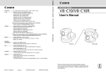
Please read this User’s Manual carefully before operation.
Be sure to read the “a Safe Use of Equipment” section before using
this equipment. Store this manual in a readily accessible location for
future reference.
VB-C50iR
Introduction
Thank you for purchasing the Canon Network Camera VB-C50i/VB-C50iR (referred to hereafter
as the VB-C50i/VB-C50iR).
This User’s Manual describes how to set up and use the VB-C50i/VB-C50iR. Read this manual carefully
before using the VB-C50i/VB-C50iR to ensure effective operation. In particular make sure that you
read the “a Safe Use of Equipment” in this manual, as well as the supplied CD-ROM ReadMe file.
For the latest information, please refer to Canon Web site.
Exclusion of Liability
If the Product is connected to a recording device (for example a VCR), Canon Inc. accepts
no responsibility whatsoever for any financial losses that may be incurred as a result of
the loss of recorded information or images, regardless of the internal or external cause of
the loss.
On Copyrights
Y
P
O
Videos, images or sounds taken or recorded with your VB-C50i/VB-C50iR may not be utilized or
published, without consent of copyright holders, if any, except in such a way as permitted for
personal use under relevant copyright law.
Notes
1. The unauthorized transfer of all or any part of the contents of this Manual is forbidden.
2. The contents of this Manual are subject to change without notice.
3. Every effort has been made to ensure that this Manual is flawless. However, if you find any
oversights, please let us know.
4. Notwithstanding the above, Canon accepts no responsibility for any effects resulting from the
use of this Manual.
C
Trademark Notices
●Canon and Canon logo are registered trademarks of Canon Inc.
●Microsoft and Windows are registered trademarks of Microsoft Corporation in the United States
and other countries.
●Windows is legally recognized as Microsoft Windows Operating System.
●Java and all Java-based marks are trademarks or registered trademarks of Sun Microsystems,
Inc. in the United States and other countries.
●Other brand or product names in this manual may be trademarks or registered trademarks of
their respective companies.
This product uses software based on the GNU General Public License (GPL), GNU Lesser General
Public License (LGPL) and the BSD License. For each of the licenses, see GPL.txt, LGPL.txt and
COPYING.txt in the LICENSE folder on the CD-ROM.
If you require the source code for a program based on GPL or LGPL, please contact either the place
of purchase or your nearest Canon Sales Company.
ii
Introduction
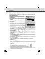
Usage Notice of Audio
* Features related to audio transmission (audio sent from camera servers to viewers)
written in this manual can be only used with the Model Names “PT-50iNv” and
“PT-50iNRv” of the VB-C50i/VB-C50iR.
Please refer to P.1-11 to confirm the Model Name of your VB-C50i/VB-C50iR.
● The audio and video may be out of sync.*
● The audio stream may be interrupted according to the performance of your PC and the
network environment.
● You cannot record audio with the viewer software.*
● You can receive audio using the Viewer for PC or the Admin Viewer.*
● You can send audio and video to up to 50 clients. However, if there are a large number
of clients, the audio stream may be interrupted.*
● The audio stream may be interrupted if you use a proxy server.
● The audio stream may be interrupted if you use anti-virus software.
Y
P
O
Request concerning disclosure of live videos and audio
With respect to the disclosure of live videos and audio, we request that sufficient
consideration be given to matters of privacy and rights not to be photographed. Canon
considers the following points concerning such matters when it operates camera sites for
which it has been responsible to install and operate:
●We take measures such as adding limitations on zoom magnifications so that people
cannot make special specifications.
●When videos are taken of specific buildings, interiors and the like, we install the camera
only after receiving approval from the administrator.
Please note that the operator of the camera site and not Canon has full responsibility
regarding the disclosure of live videos and audio.
C
■ European Union (and EEA) only.
This symbol indicates that this product is not to be disposed of with your
household waste, according to the WEEE Directive (2002/96/EC) and your
national law. This product should be handed over to a designated collection
point, e.g., on an authorized one-for-one basis when you buy a new similar
product or to an authorized collection site for recycling waste electrical and
electronic equipment (EEE). Improper handling of this type of waste could have a possible
negative impact on the environment and human health due to potentially hazardous
substances that are generally associated with EEE. At the same time, your cooperation in
the correct disposal of this product will contribute to the effective usage of natural resources.
For more information about where you can drop off your waste equipment for recycling,
please contact your local city office, waste authority, approved WEEE scheme or your
household waste disposal service.
For more information regarding return and recycling of WEEE products, please visit
www.canon-europe.com/environment.
(EEA: Norway, Iceland and Liechtenstein)
© Copyright 2007 CANON INC.
ALL RIGHTS RESERVED
iii
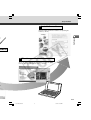
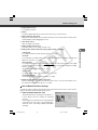
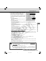
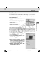
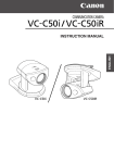
Package Contents
The VB-C50i/VB-C50iR package contains the following items. If any of these items is missing,
please contact the retailer from which you purchased the product.
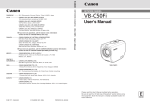
1. VB-C50i main unit
(or VB-C50iR main unit)
3. AC cable (1 meter/3 ft.)
(NTSC model only)
2. AC adapter PA-V16
(NTSC model only)
Y
P
O
4. CD-ROM
CD-ROM contents
* The cable length may differ depending
on the country in which the product was
purchased.
C
5. User’s Manual
(This document)
6. Warranty card
(NTSC model only)
ReadMe-J.txt (Japanese text containing
precautions etc. other than those in this
document)
ReadMe-E.txt (English text containing
precautions etc. other than those in this
document)
VBSetup.exe (Initial settings tool → P.2-7)*
MANUAL folder (PDF versions of this document
and the Viewer software User’s Manual)*
vbfiles folder (File system sets of sample pages
etc.)
LICENSE folder (License documents for software
built into the VB-C50i/VB-C50iR)
VBTools folder (Bundled software installer set)*
SOUND folder (Sound sample files for Audio
Playback)
* For the latest information such as the bundled
software and manual, please refer to Canon
Web site.
iv
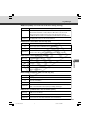
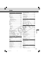
Contents
Introduction ............................................................................ ii
Package Contents .................................................................. iv
How to Read This Manual...................................................... ix
a Safe Use of Equipment...................................................... x
Maintenance .............................................................................................................. xv
Chapter 1 Before Using the VB-C50i/VB-C50iR
Features of the VB-C50i/VB-C50iR .............................................................. 1-2
Hardware and Software Requirements ....................................................... 1-4
Y
P
O
Viewer Software .......................................................................................................
VB Initial Setup Tool .................................................................................................
VB Administration Tools ...........................................................................................
VBCollector ..............................................................................................................
Multipoint Recording Software for Monitoring Use (Sold separately) ......................
1-4
1-5
1-5
1-5
1-8
System Components and Their Operation ................................................. 1-9
Multi-Terminal Module VB-EX50 (Sold Separately) .................................. 1-12
Chapter 2 Setting Up
Setup Workflow ............................................................................................. 2-2
1. Set Up the Camera .................................................................................... 2-4
C
Using a Tripod .......................................................................................................... 2-4
Using the Wide Converter ........................................................................................ 2-5
2. Connect the Camera to the Network ....................................................... 2-6
Turning the Power ON and OFF .............................................................................. 2-6
3. Perform Initial Settings for the Camera .................................................. 2-7
4. Check Operation of the Camera ............................................................ 2-10
5. Install the Software ................................................................................. 2-11
Viewer Software Overview ......................................................................... 2-12
Viewer Software Types .......................................................................................... 2-12
Features of the Viewer Software ............................................................................ 2-12
Chapter 3 Basic Settings
What Can I Do on Each of the Settings Pages? ......................................... 3-2
Accessing the Settings Title Page ............................................................... 3-3
Settings Title Page ........................................................................................ 3-4
Setting Up the Administrator Password and Ethernet etc.
(System and Network) ....................................................................... 3-5
Setting Camera Control, Image Size and Quality (Camera and Video) .... 3-7
Presetting Best Shot (Preset) .................................................................... 3-13
v
000-VBC50i-E-US
5
06.7.6, 11:30 AM
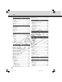
Contents
Setting Up the HTTP, Camera and Audio Servers (Server) .....................
Setting User Access Privileges (Access Control) ...................................
Setting the Date and Time (Date and Time) ..............................................
Setting Up Name Server Address and Mail etc. (Miscellaneous) ...........
Using the Administration Tools (Administration Tools) ..........................
3-16
3-21
3-24
3-26
3-29
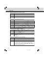
Chapter 4 VB Administration Tools
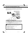
Overview of VB Administration Tools ......................................................... 4-2
Installing the VB Administration Tools ......................................................................
VBAdmin Startup Panel ...........................................................................................
Panorama Creation Tool ..........................................................................................
View Restriction Tool ................................................................................................
Preset Setting Tool ...................................................................................................
Schedule Setting Tool ..............................................................................................
Log Viewer ...............................................................................................................
Admin Viewer ...........................................................................................................
Y
P
O
4-2
4-3
4-3
4-3
4-3
4-4
4-4
4-4
Starting Up VB Administration Tools .......................................................... 4-5
Panorama Creation Tool ............................................................................... 4-7
Panorama Creation Tool Display Screen ................................................................. 4-8
Capturing Panorama Pictures .................................................................................. 4-9
Updating/Deleting Panorama Pictures ................................................................... 4-10
Reconnecting .......................................................................................................... 4-11
Opening a Panorama Picture from a Picture File/Saving
a Panorama Picture as a Picture File ......................................................... 4-11
Displaying Connection Information ......................................................................... 4-11
C
View Restriction Tool .................................................................................. 4-12
View Restriction Tool Display Screen .................................................................... 4-13
Setting View Restrictions ....................................................................................... 4-15
Preset Setting Tool ...................................................................................... 4-18
Preset Setting Tool Display Screen ........................................................................ 4-19
Setting Presets ....................................................................................................... 4-21
Preset Tour ............................................................................................................. 4-24
Schedule Setting Tool ................................................................................. 4-27
Schedule Setting Tool Display Screen (Toolbar) ....................................................
Normal Schedule ...................................................................................................
Special Schedule ...................................................................................................
Resetting Schedule Settings ..................................................................................
Setting Up Service .................................................................................................
Timer Setting Tool ..................................................................................................
Motion Detection Setting Tool ................................................................................
Night Mode Setting Tool .........................................................................................
External Device Input Setting Tool .........................................................................
External Device Output Setting Tool ......................................................................
vi
000-VBC50i-E-US
6
06.7.6, 11:30 AM
4-28
4-29
4-33
4-37
4-38
4-39
4-42
4-52
4-54
4-57
Contents
Log Viewer ................................................................................................... 4-62
Viewing the Log ..................................................................................................... 4-63
Admin Viewer .............................................................................................. 4-65
Starting Up Admin Viewer ...................................................................................... 4-66
Operating External Devices and Motion Detection ................................................ 4-66
Enabling/Disabling View Restrictions ..................................................................... 4-68
Operating a Camera .............................................................................................. 4-68
Camera-Specific Functions .................................................................................... 4-70
Sending and Receiving Audio ................................................................................ 4-71
Shade Correction ................................................................................................... 4-73
Auto Reconnection Function .................................................................................. 4-73
Restoring the Default Exposure and Focus Settings When Closing the Admin Viewer .. 4-74
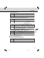
Chapter 5 Creating Web Pages for Video Distribution
Y
P
O
Web Pages for Video Distribution ............................................................... 5-2
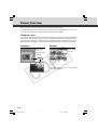
Viewer Overview ........................................................................................... 5-4
Viewer for Java ........................................................................................................ 5-4
Viewer for PC ........................................................................................................... 5-5
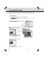
Viewing Sample Pages ................................................................................. 5-6
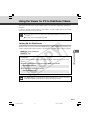
Using the Viewer for Java to Distribute Videos .......................................... 5-7
Using the Viewer for Java to Create a Web Page ................................................... 5-7
Saving Web Page Data ............................................................................................ 5-8
Example of Using the Viewer for Java to Create a Web Page ................................ 5-9
Viewer for Java Parameters ................................................................................... 5-17
C
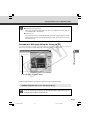
Using the Viewer for PC to Distribute Videos ........................................... 5-21
Setting Up the Web Server .................................................................................... 5-21
Creating wvh Files ................................................................................................. 5-22
Example of a Web page Using the Viewer for PC ................................................. 5-23
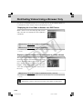
Distributing Videos Using a Browser Only ............................................... 5-24
Displaying the Live Video at Access as a Still Picture ........................................... 5-24
Displaying a Specified Number Of Live Video Frames As a Video at Access ....... 5-24
Displaying Live Video from a Specified Angle as Still Pictures .............................. 5-25
Example of Video Distribution Using One Global Address .................... 5-26
Distributing Still Images to a Mobile Phone ............................................. 5-27
Camera Control by Position Specification .............................................................. 5-28
Overwriting Sample Pages .................................................................................... 5-28
Chapter 6 Using the Picture Recording Function
Using the Still Picture Recording Function
Linked to an External Device ........................................................... 6-2
Sample Application Combining a Door-opening Sensor .......................................... 6-2
Using the Audio Playback/Recording Function
Linked to an External Device ........................................................... 6-4
Sample Application Combining a Speaker, Microphone and Door-opening Sensor .... 6-4
vii
000-VBC50i-E-US
7
06.7.6, 11:30 AM
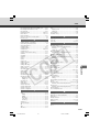
Contents
Using the Still Picture Recording Function
with a Predetermined Schedule ....................................................... 6-6
Sample Application Using a Timer ........................................................................... 6-6
Using the Motion Detection Function with a Predetermined Schedule ... 6-8
Sample application in combination with a warning device ....................................... 6-8
Using VBCollector ...................................................................................... 6-11
Installing VBCollector .............................................................................................
Starting Up VBCollector .........................................................................................
Registering a Server ..............................................................................................
Registering Tasks ...................................................................................................
Executing and Canceling Tasks .............................................................................
Details Displayed on the Task View .......................................................................
Starting/Stopping the Service ................................................................................
Automatic Downloading by Notification ..................................................................
Viewing Recorded Images and Playing Back Recorded Audio ..............................
Viewing Logs ..........................................................................................................
Setting Retention Period and Disk Space ..............................................................
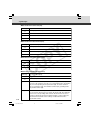
Chapter 7 Appendix
Y
P
O
6-12
6-13
6-13
6-16
6-18
6-20
6-20
6-21
6-23
6-32
6-36
Troubleshooting ............................................................................................ 7-2
Log Messages ............................................................................................... 7-4
The VB-C50i/VB-C50iR Log Messages ................................................................... 7-4
The VBCollector Log Messages ............................................................................ 7-12
C
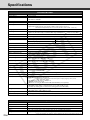
Specifications ............................................................................................. 7-16
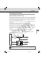
External Device I/O Terminals ................................................................................ 7-17
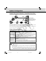
System Configuration ................................................................................ 7-18
Example of Basic System Configuration - Viewing Videos Using a Viewer ........... 7-18
Viewer Software Functions .................................................................................... 7-18
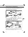
Sample Network Configurations ............................................................... 7-19
Sample LAN Environment Configuration ............................................................... 7-19
Sample Configuration in an ISP Environment ........................................................ 7-19
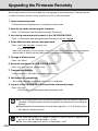
Upgrading the Firmware Remotely ........................................................... 7-20
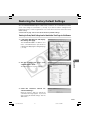
Restoring the Factory Default Settings .................................................... 7-21
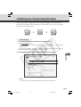
Restoring the Factory Default Settings from the Administration
Tools Page via a Web Browser ................................................................. 7-21
Restoring the Factory Default Settings from the Reset Switch .............................. 7-22
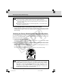
Initializing the Camera Head Position ....................................................... 7-23
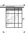
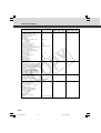
Factory Default Settings ............................................................................ 7-25
Data Capacity of Recorded Pictures and Audio ...................................... 7-27
Amount of Memory ................................................................................................. 7-27
Frame Sizes ........................................................................................................... 7-27
Amount of Audio Data ............................................................................................ 7-28
Index ............................................................................................................ 7-29
viii
000-VBC50i-E-US
8
06.7.6, 11:30 AM
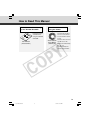
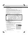
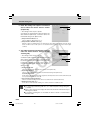
How to Read This Manual
For information about setting
up the VB-C50i/VB-C50iR
NE
TW
OR
K
CA
ME
Us
RA
er’
sM
an
ua
l
VB
Ple
Be ase
this sur rea
futu equ e to d this
re
ipm rea
inst
refe ent d
ren . Stothe “aruc
tion
ce.
re
this Safe manua
ma Use
nua of l car
l in Equ efully
a rea ipm
bef
dily ent” ore
acc sectionope
rati
ess
ible bef on.
loca ore
tion usin
g
for
-C5
0i
VB
-C5
0iR
Read this manual
carefully before
using the VB-C50i/
VB-C50iR.
User’s Manual
(This document)
C
For information about
using the Viewer
This manual describes
how to use the Viewer
for Java and the Viewer
for PC.
Sections where the user
Viewer Software
should refer to this
User’s Manual
manual are indicated by
(Viewer-E.pdf)
the d icon
accompanied by the
relevant page number.
Y
P
O
ix
000-VBC50i-E-US
9
06.7.6, 11:30 AM
a Safe Use of Equipment
a
An exclamation point, within a triangle, is intended to alert the user to the presence of
important operating and maintenance (servicing) instructions in the literature
accompanying the equipment.
a Important Warnings
a CAUTION:
TO REDUCE THE RISK OF ELECTRIC SHOCK, DO NOT REMOVE COVER (OR
BACK). NO USER-SERVICEABLE PARTS INSIDE. REFER SERVICING TO
QUALIFIED SERVICE PERSONNEL.
The serial number of this equipment may be found on the bottom of the VB-C50i/
VB-C50iR. No others have the same serial number as yours.
You should record the number and other vital information here and retain this book
as a permanent record of your purchase to aid identification in case of theft.
Date of Purchase
Dealer Purchased from
Dealer Address
Dealer Phone No.
Model No. VB-C50i or VB-C50iR
Serial No.
C
Y
P
O
For Users in the UK (PA-V16)
When replacing the fuse only a correctly rated approved type should be used and
be sure to re-fit the fuse cover.
The AC adapter can be connected to the VB-C50i/VB-C50iR from a standard AC
power outlet. Please check your instruction manual to make sure that your
VB-C50i/VB-C50iR is compatible with this adapter.
– The socket-outlet should be installed near the equipment and should be easily
accessible.
– Unplug the apparatus from the wall outlet before cleaning or maintaining.
a Important Operational Instructions
a WARNING:
TO REDUCE THE RISK OF ELECTRIC SHOCK, DO NOT EXPOSE THIS
EQUIPMENT TO RAIN OR MOISTURE.
a CAUTION:
TO REDUCE THE RISK OF ELECTRIC SHOCK AND TO REDUCE ANNOYING
INTERFERENCE, USE THE RECOMMENDED ACCESSORIES ONLY.
x
000-VBC50i-E-US
10
06.7.6, 11:30 AM
a Safe Use of Equipment
FDA regulation
This Network Camera has not been evaluated by the Food and Drug Administration
(FDA) for use as a medical device. When incorporated into a system with medical
applications, FDA regulations may apply. Therefore, please consult your legal
advisor to determine whether FDA regulations apply.
FCC NOTICE
Network Camera, Model Name: PT-50iNv, PT-50iP, PT-50iNRv, PT-50iPR
This device complies with Part 15 of the FCC Rules. Operation is subject to the
following two conditions: (1) This device may not cause harmful interference,
and (2) this device must accept any interference received, including interference
that may cause undesired operation.
Note: This equipment has been tested and found to comply with the limits for a
Class B digital device, pursuant to Part 15 of the FCC Rules. These limits are
designed to provide reasonable protection against harmful interference in a
residential installation. This equipment generates, uses and can radiate radio
frequency energy and, if not installed and used in accordance with the
instructions, may cause harmful interference to radio communications.
However, there is no guarantee that interference will not occur in a particular
installation. If this equipment does cause harmful interference to radio or
television reception, which can be determined by turning the equipment off and
on, the user is encouraged to try to correct the interference by one or more of
the following measures:
- Reorient or relocate the receiving antenna.
- Increase the separation between the equipment and receiver.
- Connect the equipment into an outlet on a circuit different from that to which
the receiver is connected.
- Consult the dealer or an experienced radio/TV technician for help.
Use of shielded cable is required to comply with class B limits in Subpart B of
Part 15 of FCC Rules.
Do not make any changes or modifications to the equipment unless otherwise
specified in the manual. If such changes or modifications should be made, you
could be required to stop operation of the equipment.
Canon U.S.A. Inc.
One Canon Plaza, Lake Success, NY 11042, U.S.A.
Tel No. (516) 328-5600
C
Y
P
O
Canadian Radio Interference Regulations
This Class B digital apparatus complies with Canadian ICES-003.
Réglementation canadienne sur les intérferences radio
Cet appareil numérique de la classe B est conforme à la norme NMB-003 du
Canada.
Dieses Produkt ist zum Gebrauch im Wohnbereich, Geschäfts- und
Gewerbebereich sowie in Kleinbetrieben vorgesehen.
xi
000-VBC50i-E-US
11
06.7.6, 11:30 AM
a Safe Use of Equipment
a IMPORTANT SAFETY INSTRUCTIONS
In these safety instructions, the word
“equipment” refers to the Canon Network
Camera VB-C50i/VB-C50iR and all its
accessories.
1. Read Instructions - All the safety and
operating instructions should be read before
the equipment is operated.
2. Retain Instructions - The safety and operating
instructions should be retained for future
reference.
3. Heed Warnings - All warnings on the
equipment and in the operating instructions
should be adhered to.
9. Power Sources - The PA-V16 AC adapter
should be operated only from the type of power
source indicated on the marking label. If you
are not sure of the type of power supply to your
home, consult your equipment dealer or local
power company.
10. Polarization - The PA-V16 AC adapter is
equipped with a polarized 2-prong plug (a plug
having one blade wider than the other).
The 2-prong polarized plug will fit into the
power outlet only one way. This is a safety
feature. If you are unable to insert the plug
fully into the outlet, try reversing the plug. If
the plug still fails to fit, contact your electrician
to replace your obsolete outlet. Do not defeat
the safety purpose of the polarized plug.
Y
P
O
4. Follow Instructions - All operating and
maintenance instructions should be followed.
5. Cleaning - Unplug this equipment from the
wall outlet before cleaning.
Wipe the equipment with a clean soft cloth. If
necessary, put a cloth in diluted neutral
detergent and wring it well before wiping the
equipment with it. Finally, clean the
equipment with a clean dry cloth. Do not use
benzene, thinner or other volatile liquids or
pesticides as they may damage the product’s
finish. When using chemically-treated
cleaning cloths, observe those precautions
accordingly.
C
Quick stops, excessive force, and uneven
surfaces may cause the equipment and cart
combination to overturn.
6. Accessories - Do not use accessories not
recommended in this manual as they may
be hazardous. Always use specified
connection cables. Connect devices correctly.
7. Water and Moisture - Hazard of electric shock
- Do not use the equipment near water or in
rainy/moist situations. Do not put a heater
near this equipment.
8. Placing or Moving - Do not place on an
unstable cart, stand, tripod, bracket or table.
The equipment may fall, causing serious
injury to a child or adult, and
serious damage to the
equipment. An equipment and
cart combination should be
moved with care.
11. Power Cord Protection - Power cords should
be routed so that they are not likely to be
walked on or pinched by items placed upon
or against them. Pay particular attention to
plugs and the point from which the cords exit
the equipment.
12. Outdoor Antenna Grounding - If an outside
antenna is connected to the equipment, be
sure the antenna is grounded so as to provide
some protection against voltage surges and
built-up static charges. Section 810 of the
National Electrical Code, ANSI/NFPA No.701984, provides information with respect to
proper grounding of the mast and supporting
structure, grounding of the lead-in wire to an
antenna discharge unit, size of grounding
conductors, location of antenna, antenna
discharge unit, connection to grounding
electrodes, and requirements for the
grounding electrode. See figure 1.
xii
000-VBC50i-E-US
12
06.7.6, 11:30 AM
a Safe Use of Equipment
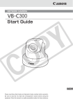
fig-1
EXAMPLE OF ANTENNA GROUNDING AS
PER NATIONAL ELECTRICAL CODE
ANTENNA
LEAD IN WIRE
GROUNDING
CLAMP
ELECTRIC
SERVICE
EQUIPMENT
ANTENNA
DISCHARGE
UNIT (NEC
SECTION 810-20)
a. When the power-supply cord or plug is
damaged.
GROUNDING
CONDUCTORS
(NEC SECTION
810-21)
b. If any liquid has been spilled onto, or
objects have fallen into, the equipment.
GROUNDING CLAMPS
NEC — NATIONAL ELECTRIC CODE
18. Damage Requiring Service - Disconnect this
equipment from the wall outlet and all power
sources including batteries, and refer
servicing to qualified service personnel under
the following conditions.
POWER SERVICE
GROUNDING ELECTRODE
SYSTEM
(NEC ART 250. PART H)
d. If the equipment does not operate normally
even if you follow the operating instructions.
Adjust only those controls that are covered
by the operation instructions. Improper
adjustment of other controls may result in
damage and will often require extensive
work by a qualified technician to restore
the equipment to its normal operation.
Y
P
O
13. Lightning - For added protection of this
equipment during a lightning storm, or when
it is left unattended and unused for long
periods of time, disconnect it from the wall
outlet and disconnect the antenna. This will
prevent damage to the equipment due to
lightning and power-line surges.
14. Power Lines - An outside antenna system
should not be located in the vicinity of
overhead power lines or other electric light
or power circuits, or where it can fall into such
power lines or circuits. When installing an
outside antenna system, extreme care should
be taken to keep from touching such power
lines or circuits as contact with them might
be fatal.
C
c. If the equipment has been exposed to rain
or water.
15. Overloading - Do not overload wall outlets and
extension cords as this can result in a risk of
fire or electric shock.
16. Object and Liquid Entry - Never push objects
of any kind into this equipment through
openings as they may touch dangerous
voltage points or short out parts that could
result in a fire or electric shock. Be careful
not to spill liquid of any kind onto the
equipment.
17. Servicing - Do not attempt to service this
equipment yourself as opening or removing
covers may expose you to dangerous voltage
or other hazards. Refer all servicing to
qualified personnel.
e. If the equipment has been dropped or the
cabinet has been damaged.
f. When the equipment exhibits a distinct
change in performance. This indicates a
need for service.
19. Replacement Parts - When replacement parts
are required, be sure the service technician
has used replacement parts that are specified
by Canon or that have the same
characteristics as the original part.
Unauthorized substitutions may result in fire,
electric shock or other hazards.
20. Safety Check - Upon completion of any
service or repairs to this equipment, ask the
service technician to perform safety checks
to determine that the equipment is in safe
operating order.
21. Do not install the equipment in the following
locations as this can cause a fire or electric
shock:
- Hot locations
- Close to a fire
- Very humid or dusty locations
xiii
000-VBC50i-E-US
13
06.7.6, 11:30 AM
a Safe Use of Equipment
- Locations exposed to direct sunlight
- Locations exposed to salt spray
- Close to flammable solvents (alcohol,
thinners, etc.)
22. When any of the following occurs,
immediately switch OFF the equipment,
unplug it from the main power supply and
contact your nearest Canon supplier. Do not
continue to use the equipment as this can
cause a fire or electric shock.
- The equipment emits any smoke, heat,
abnormal noise, or unusual odor.
- A metal object falls into the equipment.
Y
P
O
- The equipment is damaged in some way.
23. Please observe the following when using the
equipment. Failure to do so can result in a
fire or electric shock.
- Do not use flammable sprays near the
equipment.
- Do not subject the equipment to strong
impacts.
24. Make sure the power line and network cable
are implemented in a safe manner
accordingly to the related technical
regulations.
C
25. Focusing on the direct sunlight, halogen
lamp or any other high-intensity lamp for a
long time may cause damage to the image
sensor.
For CA, USA only
Included lithium battery contains Perchlorate Material – special handling may apply.
See www.dtsc.ca.gov/hazardouswaste/perchlorate/ for details.
xiv
a Safe Use of Equipment
Note
Notes on Using the Motion Detection Function, Automatic
Tracking and VBCollector
The Motion Detection Function, Automatic Tracking (→ P.4-42) and VBColletor (→
P.6-11) are not suited to applications where high levels of reliability are required.
Therefore, we recommend that you not use these functions for monitoring or other
purposes if consistently high levels of reliability are required. Canon accepts no liability
whatsoever for faults resulting from the use of the Motion Detection, Automatic
Tracking and VBCollector.
Maintenance
Cleaning the Equipment
Y
P
O
1. Unplug the AC adapter from the wall outlet.
2. Carefully wipe the equipment with a soft cloth that has
been moistened with water or a mild detergent.
a WARNING:
Do not use flammable solvents such as alcohol, benzene or thinners.
The use of such substances can cause a fire or electric shock.
C
3. Wipe with a dry cloth.
4. When you have finished, plug the AC adapter back in to the wall outlet.
Cleaning the Lens
Use a commercially available lens cleaner to remove any soiling from the lens.
● The auto-focus may not function correctly if the surface of the lens is dirty.
● Scratches on the surface of the lens will cause image defects.
Icons Used in This Instruction Manual
Note
Tip
Indicates important information that must be observed or actions that are prohibited
during an operation. These notes must be read to prevent possible faults or damage
to the equipment.
Indicates supplementary information or a reference to an operation. Users are advised
to read these memos.
d Refer to the PDF manual on the supplied CD-ROM.
xv
000-VBC50i-E-US
15
06.7.6, 11:30 AM
C
Y
P
O
xvi
000-VBC50i-E-US
16
06.7.6, 11:30 AM
Chapter
Y
P
O
Before Using the
C
VB-C50i/VB-C50iR
This chapter describes the features of the VB-C50i/VB-
C50iR, the hardware and software requirements, and the
name and functions of the system components.
001-VBC50i-E-US
1
06.7.6, 11:33 AM
Features of the VB-C50i/VB-C50iR
The VB-C50i/VB-C50iR is a system that distributes live videos via the Internet or an intranet. It
can be used in a wide range of applications, such as distributing live videos from a Web site or
monitoring. The system is configured for the VB-C50i/VB-C50iR and viewer software. Please use
the supplied viewer software for viewing videos distributed by the VB-C50i/VB-C50iR and controlling
cameras (→ P.1-4, 2-12).
Broadband Video Distribution function
The VB-C50i/VB-C50iR is capable of capturing videos at up to 30 fps (NTSC)/25 fps (PAL).
Motion-JPEG type is used to compress video images. For networking, auto-negotiation between
Ethernet 100Base-TX/10Base-T is provided and a leased line or ADSL can also be used through
a router. Since video quality and the frame rate can be freely set, videos can be distributed under
conditions that best suit the network bandwidth.
* Please refer to P.1-11 to confirm whether your VB-C50i/VB-C50iR is PAL model or NTSC model.
Y
P
O
Concurrent video is distributed up to 50 clients
Up to 50 clients can view video at the same time from a single VB-C50i/VB-C50iR.
Camera and video distribution server functions housed in a single unit
The camera capable of full pan, tilt, and zoom functions and its server functions for distributing
videos through a network are compactly housed in a single unit. By simply connecting a LAN
cable and a power supply, the unit can distribute live videos from any location* where it is installed.
* The unit cannot be installed in locations subject to direct sunlight, high temperatures, high humidity, or
other adverse conditions (→ P.xiii, xiv).
High-performance 26x zoom and wide angle photographic range
C
The camera section is equipped with a 26x zoom lens. Furthermore, since the VB-C50i provides
a pan angle of 200 degrees (100 degrees each to the left and right) and a tilt angle of 120
degrees (90 degrees up and 30 degrees down), and the VB-C50iR provides a pan angle of 340
degrees (170 degrees each to the left and right) and a tilt angle of 100 degrees (10 degrees up
and 90 degrees down), the VB-C50i/VB-C50iR are capable of shooting wide areas.
Can be mounted on ceilings, etc. (VB-C50iR)
The VB-C50iR includes a mounting plate, enabling it to be mounted in a variety of locations
including ceilings*. The shape of the camera head has been designed so that pan and tilt operations
are still possible when mounted upside down.
* The unit cannot be installed in locations subject to direct sunlight, high temperatures, high humidity, or
other adverse conditions (→ P.xiii, xiv).
Remote camera control from the viewer
The VB-C50i/VB-C50iR come with two types of viewer software: the Viewer for PC and the Viewer
for Java. The viewers give you full remote control of the camera angle (pan and tilt) and zoom
magnification of the VB-C50i/VB-C50iR, allowing you to view videos with plenty of ambiance.
Panorama picture creation functions and settings
The entire photographic range of the camera can be created and saved as a panorama picture.
The saved panorama pictures can then be easily used to visually set view restrictions and presets.
Shade Correction function
If the background of an image is bright, making the subject difficult to see, you can adjust the
1-2
001-VBC50i-E-US
2
06.7.6, 11:33 AM
Features of the VB-C50i/VB-C50iR
contrast of the darker areas to make it easier to see. Unlike backlight compensation, the shade
correction feature allows image processing without adversely affecting the existing lighter regions.
Camera Position Preset function
Before Using the VB-C50i/VB-C50iR
If often-used camera angles (camera head aim and zoom position) and related items are saved
in advance as presets, the camera can be controlled from the viewer by simply selecting a desired
preset. Up to 20 presets can be stored.
View Restriction function
You can set restrictions on camera angle specifications and zoom magnifications to prevent
viewers from seeing certain camera angles. For example, if the VB-C50i/VB-C50iR is showing
camera footage on the Internet, it is possible to distribute videos while protecting privacy (→ P.iii,
“Request concerning disclosure of live videos and audio”).
More powerful security functions
Y
P
O
The destinations for video distributions can be restricted based on passwords. Up to 50 clients
can be registered.
Using preset schedules or links with external devices to record pictures or
audio*
Using the Multi-Terminal Module (→ P.1-12), you can set picture and audio recording* based on
ON/OFF input from an external device and from previously-set schedules. If VBCollector is used,
images and sound recorded* by the VB-C50i/VB-C50iR can be automatically collected so that
you can view the images and play back the audio data* on a PC.
* Only available with two particular models (→ P.iii)
Audio Playback
C
Using the Multi-Terminal Module (→ P.1-12), you can connect a speaker with amp to the camera.
Then, you can register your favorite audio files or sample files recorded on a CD-ROM and play
the registered files based on ON/OFF input from an external device and from previously-set
schedules.
Audio transmission
Using the Multi-Terminal Module (→ P.1-12), you can connect a microphone* and speaker with
amp to the camera and then send and receive audio* via the Viewer.
* Only available with two particular models (→ P.iii)
Night mode shooting
Using the built-in infrared light (effective lighting range: approx. 3m [9.8ft.]), you can take pictures
even in darkness.
* When using a dome housing with the VB-C50i/VB-C50iR, the infrared light cannot be used.
Motion detection function and automatic tracking function
You can perform external device control, video and audio recording* by detecting changes in the
image caused by motion of people or objects. Automatic tracking of moving objects is also available.
* Only available with two particular models (→ P.iii)
Service settings with schedule function
You can start up motion detection and external device services by setting up a visual and easyto-understand schedule in the calendar.
001-VBC50i-E-US
3
06.7.6, 11:33 AM
1-3
Hardware and Software Requirements
For the latest information, please refer to Canon Web site.
Viewer Software (→ d Viewer Software User’s Manual)
The viewer software that is supplied with the VB-C50i/VB-C50iR lets you view the video captured
by the VB-C50i/VB-C50iR and control the camera.
Viewer for Java Ver. 3.6
Operating System/
Web Browser
Windows 2000(SP4) / Internet Explorer 6.0(SP1), Netscape 7.1 or 7.2
Windows XP(SP1a) / Internet Explorer 6.0(SP1), Netscape 7.1 or 7.2
Windows XP(SP2) / Internet Explorer 6.0(SP2) or 7.0, Netscape 7.1 or 7.2
Windows Server 2003 Standard Edition / Internet Explorer 6.0, Netscape 7.1 or 7.2
Windows Server 2003 Standard Edition (SP1)
/ Internet Explorer 6.0(SP1) or 7.0, Netscape 7.1 or 7.2
Windows Server 2003 Standard Edition (SP2) / Internet Explorer 6.0(SP2) or 7.0
Windows Server 2003 R2 Standard Edition / Internet Explorer 6.0(SP1) or 7.0
Windows Server 2003 R2 Standard Edition (SP2) / Internet Explorer 6.0(SP2) or 7.0
Java VM
MSVM Release 5.0.0.3810 (Java VM provided by Microsoft)
Java Plug-in 1.4.2 (Java VM provided by Sun Microsystems)
Y
P
O
* Java VM must be installed beforehand. If the Java VM provided by Microsoft has not been installed,
please access Sun Microsystems Website to download the Java VM provided by Sun Microsystems.
* Not compatible with Java Plug-in 1.5.0 or later (Java VM provided by Sun Microsystems).
* This viewer may not run stably on operating systems and Web browsers other than those listed above.
C
Viewer for PC Ver. 3.6
Operating System/
Web Browser
Windows 2000(SP4) / Internet Explorer 6.0(SP1), Netscape 7.1 or 7.2
Windows XP(SP1a) / Internet Explorer 6.0(SP1), Netscape 7.1 or 7.2
Windows XP(SP2) / Internet Explorer 6.0(SP2) or 7.0, Netscape 7.1 or 7.2
Windows Server 2003 Standard Edition / Internet Explorer 6.0, Netscape 7.1 or 7.2
Windows Server 2003 Standard Edition (SP1)
/ Internet Explorer 6.0(SP1) or 7.0, Netscape 7.1 or 7.2
Windows Server 2003 Standard Edition (SP2) / Internet Explorer 6.0(SP2) or 7.0
Windows Server 2003 R2 Standard Edition / Internet Explorer 6.0(SP1) or 7.0
Windows Server 2003 R2 Standard Edition (SP2) / Internet Explorer 6.0(SP2) or 7.0
* Must be installed from the supplied CD-ROM (→ P.2-11).
Note
1-4
● The manual for the viewer software is on the supplied CD-ROM (Viewer-E.pdf).
● Although older versions of viewers can be used, some of the features are different.
Therefore, we recommend you to use the latest version.
Hardware and Software Requirements
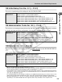
VB Initial Setup Tool Ver. 2.1 (→ P.2-7)
This tool is for performing initial settings for the VB-C50i/VB-C50iR.
Windows 2000(SP4) / Internet Explorer 6.0(SP1)
Windows XP(SP1a) / Internet Explorer 6.0(SP1)
Windows XP(SP2) / Internet Explorer 6.0(SP2) or 7.0
Windows Server 2003 Standard Edition / Internet Explorer 6.0
Windows Server 2003 Standard Edition (SP1) / Internet Explorer 6.0(SP1) or 7.0
Windows Server 2003 Standard Edition (SP2) / Internet Explorer 6.0(SP2) or 7.0
Windows Server 2003 R2 Standard Edition / Internet Explorer 6.0(SP1) or 7.0
Windows Server 2003 R2 Standard Edition (SP2) / Internet Explorer 6.0(SP2) or 7.0
Before Using the VB-C50i/VB-C50iR
Operating System/
Web Browser
VB Administration Tools Ver. 2.2 (→ P.4-2)
Y
P
O
This tool lets you create panorama pictures from the VB-C50i/VB-C50iR and then easily use them
to visually set view restrictions and presets. You can also set schedules with this tool.
Operating System/
Web Browser
Windows 2000(SP4) / Internet Explorer 6.0(SP1)
Windows XP(SP1a) / Internet Explorer 6.0(SP1)
Windows XP(SP2) / Internet Explorer 6.0(SP2) or 7.0
Windows Server 2003 Standard Edition / Internet Explorer 6.0
Windows Server 2003 Standard Edition (SP1) / Internet Explorer 6.0(SP1) or 7.0
Windows Server 2003 Standard Edition (SP2) / Internet Explorer 6.0(SP2) or 7.0
Windows Server 2003 R2 Standard Edition / Internet Explorer 6.0(SP1) or 7.0
Windows Server 2003 R2 Standard Edition (SP2) / Internet Explorer 6.0(SP2) or 7.0
* Must be installed from the supplied CD-ROM (→ P.2-11).
C
VBCollector Ver. 3.0 (→ P.6-11)
This tool is for collecting and viewing pictures and audio recorded* by the VB-C50i/VB-C50iR on
a PC.
* Only available with two particular models (→ P.iii)
Operating System/
Web Browser
Windows 2000(SP4) / Internet Explorer 6.0(SP1)
Windows XP(SP1a) / Internet Explorer 6.0(SP1)
Windows XP(SP2) / Internet Explorer 6.0(SP2) or 7.0
Windows Server 2003 Standard Edition / Internet Explorer 6.0
Windows Server 2003 Standard Edition (SP1) / Internet Explorer 6.0(SP1) or 7.0
Windows Server 2003 Standard Edition (SP2) / Internet Explorer 6.0(SP2) or 7.0
Windows Server 2003 R2 Standard Edition / Internet Explorer 6.0(SP1) or 7.0
Windows Server 2003 R2 Standard Edition (SP2) / Internet Explorer 6.0(SP2) or 7.0
Hard Disk
Minimum 4 GB required for each camera server. 30 GB or larger recommended
(NTFS format)
* Must be installed from the supplied CD-ROM (→ P.2-11).
* Pictures saved in VBCollector version 2.1 or earlier cannot be viewed in VBCollector 3.0. During installation,
you can choose whether to uninstall old versions of VBCollector (→ P.6-12).
* If you configure your system to record pictures per second with camera servers and perform the maximum
of 16 tasks (→ P.6-17) at the same time, it is recommended that you use a desktop PC with Pentium 4 2.2
GHz and 512 MB RAM or greater.
* It is recommended that you configure to collect up to 10,000 still pictures/day per a camera server. If the
total amount of still pictures exceeds this value, it may take several minutes to display all the pictures.
* Running VBCollector on a PC that is already running the Network Video Recorder VK-64/VK-16 (sold
separately) is not recommended due to the high CPU load. They should be run on separate PCs.
1-5
Hardware and Software Requirements
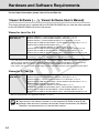
Using the VB-C50i/VB-C50iR with Windows XP SP2...
Note
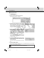
If you use the VB Initial Setup Tool or VBCollector with Windows XP SP2, you will need to
change your Windows firewall settings on your PC.
VB Initial Setup Tool
If you installed the VB Initial Setup Tool on a PC with Windows XP SP2 and try to launch the
tool, you may encounter a “Windows Security Alert” dialog.
If the Windows Security Alert dialog appears, click “Unblock”. Once you click the Unblock
button, the dialog box will not be displayed again.
Settings are now complete.
VBCollector
If you installed the VBCollector on a PC with Windows XP SP2 and used the Automatic
Download by Notification function, please follow the procedures as described below.
After installation of the VBCollector:
Y
P
O
1. From the Windows “Start” menu, launch the “Control Panel”.
2. In Control Panel, select “Windows Firewall”.
If Windows Firewall is not shown, select “Security Center” and then select “Windows
Firewall”.
3. In the Windows Firewall dialog box, select the “Exception” tab and then
click “Add Program”.
C
4. In the “Add a Program” dialog box, click “Browse”.
In the Browse dialog box, select the location where you installed the VBCollector and
enter the file name as “VBCICSM.exe”.
5. In the Windows Firewall dialog box, your program is now listed. Make
sure it is enabled (checked). Click “OK” to close the dialog box.
Settings are now complete.
If you finish setting the VB Initial Setup Tool (initial settings) or wish to stop the Automatic
Download by Notification function using VBCollector, we recommend you to restore your
Windows firewall settings on your PC.
1. Launch the Windows Firewall dialog box and then select the “Exception”
tab (Refer to 1, 2 and 3 processes of the “VBCollector” for details).
2. Select a program you wish to restore and click “Delete”.
VB Initial Setup Tool: VB Initial Setup Tool Ver. 2.1
VBCollector: VBCICSM.exe
3. A confirmation dialog appears. Click “Yes” to delete the program.
1-6
001-VBC50i-E-US
6
06.7.6, 11:33 AM
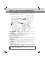
Hardware and Software Requirements
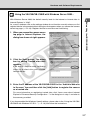
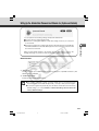
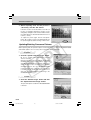
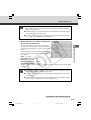
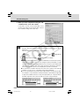
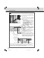
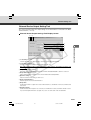
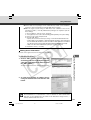
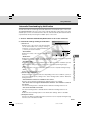
Using the VB-C50i/VB-C50iR with Windows Server 2003...
Note
Before Using the VB-C50i/VB-C50iR
With Windows Server 2003, the default security level for the Internet or intranet sites in
Internet Explorer is “High”.
As a result, windows such as the settings window do not function normally unless you first
register the site in the contents block dialog box that appears when you access the camera
server top page (→ P.2-10). Register the site to ensure normal functioning.
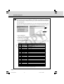
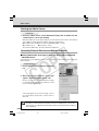
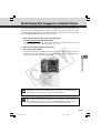
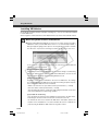
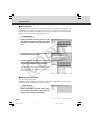
1. When you access the camera server
top page in Internet Explorer, the
dialog box shown at right appears.
Y
P
O
2. Click the [Add] button. The dialog
box for adding Trusted sites then
appears.
C
If the box for “Require server verification
(https:) for all sites in this zone” is ticked,
remove the tick.
3. Enter the IP address of the VB-C50i/VB-C50iR in the “Add this Web site
to the zone” box and then click the [Add] button to register the camera
as a trusted site.
For more information on registering trusted sites, click “Learn more about Internet
Explorer’s Enhanced Security Configuration...” in the dialog box in step 1 and refer to
the summary provided.
If you have enabled the Windows firewall settings, please refer to the “Using the VB-C50i/
VB-C50iR with Windows XP SP2...” (→ P.1-6) and follow the instructions.
1-7
Hardware and Software Requirements
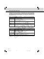
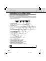
Multipoint Recording Software for Monitoring Use (Sold separately)
Videos distributed from the VB-C50i/VB-C50iR can be recorded, and recorded video can be
displayed with the software.
Network Video Recorder VK-64/VK-16 v1.2 (Viewer System Requirements)
Minimum
CPU
Pentium 4 2.2GHz or greater
Operating System
Windows 2000 Server (with SP4)
Windows 2000 Professional (with SP4)
Windows XP Professional (with SP2)
Windows Server 2003 Standard Edition (with SP1)
Windows Server 2003 R2
Memory
1 GB RAM or greater
For more than 16 Camera Servers, 1 GB or greater required.
Y
P
O
Hard Disk
2GB HDD or greater
Display
1024 × 768 with 16 bit color
A high performance video card is desirable. With PCI video cards, display performance
may be reduced.
Network Video Recorder VK-64/VK-16 v1.2 (Storage Server System Requirements)
Minimum
CPU
Pentium 4 2.2GHz or greater
Operating System
Windows 2000 Server (with SP4)
Windows 2000 Professional (with SP4)
Windows XP Professional (with SP2)
Windows Server 2003 Standard Edition (with SP1)
Windows Server 2003 R2
Memory
1 GB RAM or greater
Hard Disk
20 GB HDD or greater, SCSI or IDE, NTFS formatted
C
For more than 48 Camera Servers, 1.5 GB or greater required.
The requirements for Storage Server will vary according to the environment you will use (number of Camera
Servers, setting of recording frame rate etc.). Please contact dealers that handle Canon products for further
information.
1-8
001-VBC50i-E-US
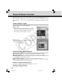
8
06.7.6, 11:33 AM
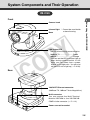
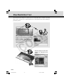
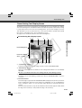
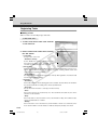
System Components and Their Operation
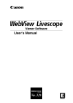
VB-C50i
Front
Infrared light
Base
Rear
C
Before Using the VB-C50i/VB-C50iR
Camera head
* Cannot be used inside
a dome housing.
Y
P
O
LAN status LED
The LED blinks during communication.
100Base-TX .......................... Green
10Base-T ............................... Orange
* You can set the LED to always light up
even during communication. In this
case, you can select from a green,
orange or red light color. You can also
set the LED not to light up (→ P.3-28).
100/10 BT Ethernet connector
(100Base-TX, 10Base-T Auto-Negotiation)
Multi-connector
You can connect the Multi-Terminal
Module VB-EX50 to the VB-C50i/VBC50iR via the connector (→ P.1-12).
Power connection socket
1-9
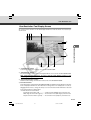
System Components and Their Operation
VB-C50iR
Front
Mounting plate
LAN status LED
The LED blinks during communication.
100Base-TX .......................... Green
10Base-T ............................... Orange
* You can set the LED to always light up
even during communication. In this case,
you can select from a green, orange or
red light color. You can also set the LED
not to light up (→ P.3-28).
Y
P
O
Base
Infrared light * Cannot be used inside
a dome housing.
Camera head
Rear
C
Power connection socket
Multi-connector
You can connect the Multi-Terminal
Module VB-EX50 to the VB-C50i/VBC50iR via the connector (→ P.1-12).
100/10 BT Ethernet connector
(100Base-TX, 10Base-T Auto-Negotiation)
1-10
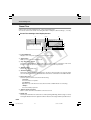
System Components and Their Operation
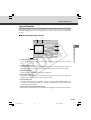
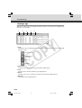
Bottom
On the bottom of the VB-C50i/VB-C50iR there are the MAC address required for network settings,
a Reset switch that returns the factory default settings and the serial number.
Screw hole for tripod mounting
Model Name
VB-C50i VB-C50iR
NTSC PT-50iNv PT-50iNRv
PAL
PT-50iP
PT-50iPR
Y
P
O
Serial No.
The serial number for this
unit is shown here.
Reset switch
You can revert all settings of
the unit to the factory default
settings by pressing this
button with a thin-tipped
object while turning on the
power switch, and keeping
the button pressed for more
than five seconds after
turning on (→ P.7-22).
00008501F162
C
Reset switch
You can revert all settings of
the unit to the factory default
settings by pressing this
button with a thin-tipped
object while turning on the
power switch, and keeping
the button pressed for more
than five seconds after
turning on (→ P.7-22).
Before Using the VB-C50i/VB-C50iR
VB-C50i
MAC address
The MAC address is
required when setting the
IP address and making
other network settings.
Please make a note of it
before installing this unit
(→ P.2-8).
VB-C50iR
Serial No.
The serial number for this
unit is shown here.
MAC address
The MAC address is
required when setting the
IP address and making
other network settings.
Please make a note of it
before installing this unit
(→ P.2-8).
1-11
001-VBC50i-E-US
11
06.7.6, 11:33 AM
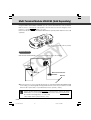
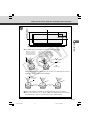
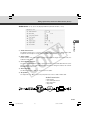
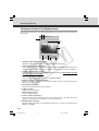
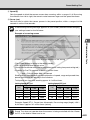
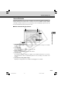
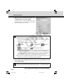
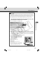
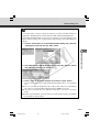
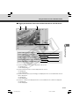
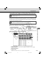
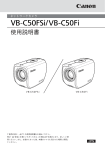
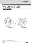
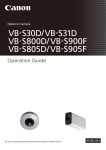
Multi-Terminal Module VB-EX50 (Sold Separately)
Using the Multi-Terminal Module VB-EX50, you can connect external devices such as different
kinds of sensors, a microphone* and speaker to the unit, and you can store image by sensor
response, or send and receive* audio (→ P.7-17).
Please note that the Multi-Terminal Module VB-EX50 is an optional product and is therefore sold
separately.
* Audio input is only available with two particular
models (→ P.iii).
Example of Use
Y
P
O
With the Multi-Terminal Module, you can perform settings such as the following.
VB-C50iR
Sensor A
C
Sensor B
Multi-Terminal Module
VB-EX50
Ethernet
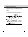
● The door open-close sensor responds when the door is opened and with the VB-C50iR installed
on the ceiling, you can photograph an image and monitor the scene every second for 3 seconds
before the door opens and for 7 seconds after the door is opened (→ P.6-2).
Tip
Using a speaker with amp and microphone* connected to the camera, the Viewer
Administrator can converse with the person in front of the camera, hear and record*
the sounds in the background (→ P.3-19, 3-20).
* Only available with two particular models (→ P.iii)
1-12
001-VBC50i-E-US
12
06.7.6, 11:33 AM
Chapter
Y
P
O
Setting Up
C
This chapter explains how to set up the VB-C50i/VB-C50iR,
run initial checks, and confirm that the camera’s images are
displayed correctly.
002-VBC50i-E-US
1
06.7.6, 11:33 AM
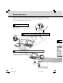
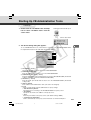
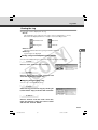
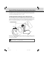
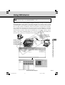
Setup Workflow
The flow for setting up and checking the camera’s images involves performing various settings
after the device is set up and your PC and the network are connected via the hub. Then, check to
see if you can display images from the camera.
1 Se t up the c a m e ra
Set up the device.
Make sure the device is set up properly (→ P.2-4).
Y
P
O
2 C onne c t the c a me r a to the ne t w or k
VB-C50i
Connect the camera and your PC via the hub (→ P.2-6).
LAN cable
Hub
C
3 Pe r fo r m i ni ti a l s e t ti ngs f or the c a me r a
Insert the CD-ROM provided into your
PC and perform initial settings following
instructions on the screen (→ P.2-7).
Supplied CD-ROM
2-2
002-VBC50i-E-US
2
06.7.6, 11:33 AM
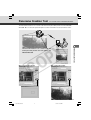
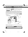
4 C h ec
Access the dev
from the top pa
Setup Workflow
5 I ns t a l l the s of tw a r e
Install the required software in advance for operating the
camera (→ P.2-11).
Setting Up
et w o rk
Y
P
O
4 C h e c k ope r a ti on of the c a me r a
C
Access the device with your PC, then display to check the image
from the top page of the camera server (→ P.2-10).
M
2-3
002-VBC50i-E-US
3
06.7.6, 11:33 AM
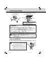
1. Set Up the Camera
Firstly, set up the camera. Read the following carefully and make sure the camera is set up properly.
VB-C50iR Installation
Firmly tighten the 2 screws (not supplied).
VB-C50i Installation
Install in a flat and stable location.
Mounting plate
VB-C50iR
Screw
Screw
(Installation)
• Distance between tapped holes: 120 mm (4.72 in.)
• Tapped hole diameter: 6.0 mm (0.24 in.)
• Mounting plate thickness: 1.6 mm (0.06 in.)
a WARNING:
Y
P
O
Install the camera securely.
● When installing the VB-C50iR on the ceiling, contact your Canon dealer.
● When installing the VB-C50iR on the ceiling, check that the ceiling is strong enough to
bear the weight of the VB-C50iR including the mounting plate. Installation in a weak
location could result in the VB-C50iR falling and causing serious injury.
● At least once a year, check for looseness in the camera installation mount. (If the optional
wide converter is used, check the converter mount also).
Note
C
● The permissible camera installation angles are ±20° from the horizontal. (±15°
when the optional wide converter is used for the VB-C50i).
● The MAC address required when making network settings is shown on the bottom of
the VB-C50i/VB-C50iR (→ P.1-11). Please make a note of it before installing this unit.
Using a Tripod (VB-C50i)
The screw for mounting a tripod is on the bottom of the VB-C50i toward the front.
Note
● Do not overtighten the mounting screw.
If excessive force is used to tighten the mounting
screw, camera head movement may be impeded,
or other malfunctions may result.
● Always use a tripod mounting screw that is less
than 6.0 mm (0.24 in.) in length. The use of
screws 6.0 mm (0.24 in.) long or longer could
damage the camera. Also, the tripod seat used
should be at least 30 mm (1.18 in.) in diameter.
30 mm
(1.18 in.)
or wider
Mounting
screw
2-4
002-VBC50i-E-US
4
Less than
6.0 mm
(0.24 in.)
06.7.6, 11:33 AM
1. Set Up the Camera
Using the Wide Converter (VB-C50i)
The optional Wide Converter WL-37 can be used to provide wide-angle shots (approx. 0.74× the
normal focal distance).
Mount the wide converter correctly so that it is level and fitted securely onto the camera. When
mounted correctly, the wide converter should turn roughly 3 times before stopping.
Setting Up
Wide Converter
a WARNING:
Y
P
O
The Wide Converter WL-37 is designed specifically for the VB-C50i and cannot be
used on the VB-C50iR.
Note
● The camera may not operate correctly if a wide converter other than the WL-37
is used.
● The permissible range of camera installation angles with the wide converter mounted
on the camera is ±15° from the horizontal.
● If you use the optional Wide Converter WL-37, set the zoom lens to the wide-angle
end. If you set the zoom lens to the telephoto end, the image resolution will be
affected and the auto focus might have problems.
● When the Wide Converter has been set for use in “Camera and Video” (→ P.3-8),
the pan and tilt values change for the three functions listed below. If the Wide
Converter is to be used, pan and tilt values must be determined after the use of the
Wide Converter has been set in “Camera and Video”.
• Home position setting (→ P.3-10)
• View restrictions (→ P.3-10)
• Preset settings (→ P.3-13)
● When the Wide Converter has been set for use in “Camera and Video” (P. 3-10),
the infrared light cannot be used (→ P.4-70).
C
○○○○○○
Setup is now complete.
2-5
002-VBC50i-E-US
5
06.7.6, 11:33 AM
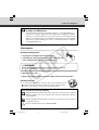
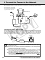
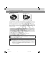
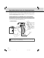
2. Connect the Camera to the Network
Next, connect the camera. Connect the camera to the network by connecting the camera and PC
via the hub with a LAN cable .
* Do not plug the AC cable power
plug into the wall socket yet.
(Rear of main unit)
AC cable
Hub
PC
Y
P
O
LAN cable
AC adapter
Turning the Power ON and OFF
The VB-C50i/VB-C50iR itself does not have a power switch. You can switch the VB-C50i/VBC50iR on by plugging the AC adapter into a wall outlet. The LED flashes when the VB-C50i/VBC50iR is communicating. When the power supply is turned ON, the LED momentarily flashes.
C
to AC outlet
Main unit
AC adapter
AC cable
Note
2-6
● The camera head position is automatically initialized when the power supply is
turned ON from OFF.
● Never touch the camera head during initialization as this could prevent
successful initialization and cause faults.
● Wait at least 5 seconds before turning the power back on after shutting it off. Turning
it on too quickly may result in a malfunction. Observe the precautions given in “a
Safe Use of Equipment/a IMPORTANT SAFETY INSTRUCTIONS” (→ P.xii).
● If the picture and audio recording* function is being used, shutting off the
power or restarting the VB-C50i/VB-C50iR will delete all the pictures and audio*.
* Only available with two particular models (→ P.iii)
○○○○○○○○○○○
The network connection is now complete.
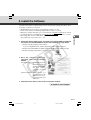
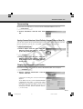
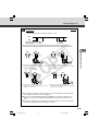
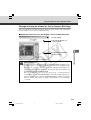
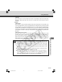
3. Perform Initial Settings for the Camera
Once your PC and the camera are connected, perform the initial settings next. The instructions
here follow on from “2. Connect the Camera to the Network”, where one camera is connected to
a PC as an example.
Installation Example
VB-C50i
Setting Up
LAN cable
Hub
Y
P
O
1. Turn on the network device (in this case, the hub) and then your PC.
Do not turn on the camera at this stage.
Note
C
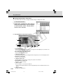
2. Insert the CD-ROM provided into your PC and from Explorer etc. double-click
“VBSetup.exe” to start the VB Initial Setup Tool. Turn on the VB-C50i.
Supplied CD-ROM
○○○○○○○○○
Continued on the following page. a
2-7
002-VBC50i-E-US
7
06.7.6, 11:33 AM
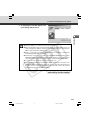
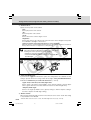
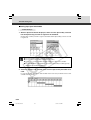
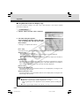
3. Perform Initial Settings for the Camera
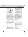
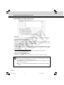
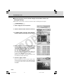
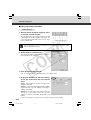
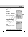
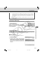
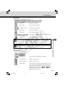
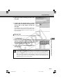
3. The camera connected to the network
is automatically detected and its MAC
address, IP address and model name
are displayed.
Click to select
The factory default setting is:
IP address : 192.168.100.1
The MAC address can be found on the white
label attached on the bottom of the unit.
Note that VBSetup.exe cannot be used across
subnets.
Click the MAC address to select it, and click
the “Initial Setup” button.
Y
P
O
4. Enter the user name “root” and the
factory default password “VB-C50i”
and enter the IP address and subnet
mask.
If you want to specify a default gateway
address, enable the “Set the default route to
Ethernet” check box and then enter the default
gateway address.
C
Although the time zone and video signal can
also be specified here, there is basically no
need to change the time zone setting.
Once you have entered your settings, click the
“OK” button.
Note
Tip
For Windows XP SP2 users, see “Using the VB-C50i/VB-C50iR with Windows XP
SP2” (→ P.1-6). This Note holds true for users who have turned on Windows Firewall
with Window Server 2003 Standard Edition (SP1).
● The password for both the VB-C50i and the VB-C50iR is “VB-C50i”.
● The MAC address for this unit is shown on the bottom of the VB-C50i/VB-C50iR
(→ P.1-11).
● The IP address 192.168.100.1 is used as the factory default setting. Please set an
IP address that suits the environment in which the VB-C50i/VB-C50iR is to be
used.
2-8
002-VBC50i-E-US
8
06.7.6, 11:33 AM
3. Perform Initial Settings for the Camera
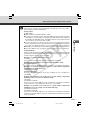
5. A setup progress window appears and
your settings will be saved.
Setting Up
Note
● Set the IP address to a value that suits your environment.
● Where the IP address has been automatically obtained from the DHCP server, you
cannot change the IP address setting from the VB Initial Setup Tool. Change the IP
address from the Network Settings page (→ P.3-6).
● Please consult with your network administrator for the IP address, subnet mask
and default gateway address settings.
● If 20 minutes or more have passed since the VB-C50i/VB-C50iR was turned on, the
VB-C50i/VB-C50iR stops sending requests for IP addresses allocation and they
cannot be detected using this tool. If this occurs, restart the VB-C50i/VB-C50iR.
● To restore the factory default settings, refer to page 7-21.
● If you are using the Multi-Terminal Module and are changing the connection of the
VB-C50i/VB-C50iR and external camera, be sure to do this after having turned off
the power of these 2 devices. After changing the connection, turn on the external
camera first and then the VB-C50i/VB-C50iR.
C
Y
P
O
○○○○○○○○○
Initial settings are now complete.
2-9
002-VBC50i-E-US
9
06.7.6, 11:33 AM
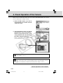
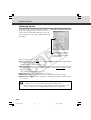
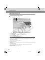
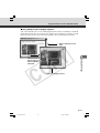
4. Check Operation of the Camera
When you have completed the initial setup, check that the VB-C50i/VB-C50iR works normally.
Use the sample page to simplify checking.
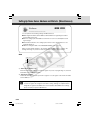
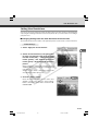
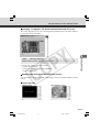
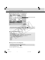
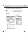
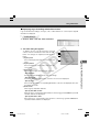
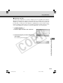
1. Select the MAC address you want to
check operation of and then click the
“Open Test Page”.
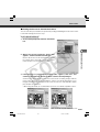
2. Your Web browser starts up and the
top page of the camera server appears.
Click the “Using Viewer for Java” or the
“Using Viewer for PC” and check that
the video is displayed properly.
Y
P
O
Below is a description of what happens when
you click “Viewer for Java”.
C
Camera Selection box
Allows you to switch cameras
when an external camera is
connected.
Note
Tip
For Windows Server 2003 users, see “Using the VB-C50i/VB-C50iR with Windows
Server 2003” (→ P.1-7).
● To use the Viewer for Java, you need to install Java VM beforehand.
● To use the Viewer for PC, you must install the Viewer for PC beforehand (→ P.2-11).
● We recommend that you perform panorama picture settings (→ P.4-7).
○○○○○○○○○○
Check of operation is now complete.
2-10
002-VBC50i-E-US
10
06.7.6, 11:33 AM
5. Install the Software
Setting Up
You must install software to display images from the camera and to manage the camera. There
are 3 types of software you can install.
• VB Administration Tools: Software for managing the camera (→ P.4-2).
• Viewer for PC: Software for displaying images from the camera (→ P.2-12).
• VBCollector: Software that allows you to collect pictures and audio recorded* by the camera
on a PC and view the recorded images and play back the audio data* on the PC (→ P.6-11).
When using older versions of VBCollector, please refer to page 6-12.
* Only available with two particular models (→ P.iii)
1. Check that all other applications are closed, insert the CD-ROM included with
the camera into the CD-ROM drive of your PC and follow the steps below.
1 Double-click [My Computer] on the desktop.
If you are using Windows XP, click the [Start] button and then [My Computer].
Y
P
O
2 Double-click the CD-ROM icon displayed and then double-click the [VBTools] folder.
3 Double-click [VBToolsInstall.exe] to start the installation.
2. Once the starting screen has
appeared, select the installation
method.
Easy Installation:
C
VB Administration Tools
and Viewer for PC are
automatically installed.
The basic software
required is installed
easily.
Custom Installation: Select whether you
want to install the VB
Administration Tools,
the Viewer for PC or the
VBCollector.
○○○○○○○○
3. Follow the instructions on the screen to install the software.
Installation is now complete.
2-11
002-VBC50i-E-US
11
06.7.6, 11:33 AM
Viewer Software Overview
By using the Viewer software, you can view images sent from the VB-C50i/VB-C50iR on a PC, as
well as control the camera. Below is an outline of the Viewer software. For details, please refer to
“Viewer Overview” (→ P.5-4) or to the Viewer Software User’s Manual (Viewer-E.pdf) on the CDROM.
Viewer Software Types
There are 2 types of viewers described below.
● Viewer for PC
When started up, this viewer displays as a separate
window. The viewer is installed beforehand on the PC
to be used. For installation details, please refer to “5.
Install the Software” in this Chapter (→ P.2-11).
Y
P
O
● Viewer for Java
The viewer appears in the Web browser. You need to
install Java VM beforehand.
C
Features of the Viewer Software
● Pan, tilt and zoom control: You can control pan, tilt and zoom with the scroll bars.
● Backlight adjustment: You can brighten the image when it is dark due to backlight.
● Panorama window display: You can control the camera by clicking on the panorama window
or by dragging the frame inside the window.
● Image saving and printing: You can save and print snapshots of live images.
● Audio reception (Viewer for PC only): You can receive audio sent from the VB-C50i/VBC50iR. (Only available with two particular models)
Hardware and Software Requirements
Please refer to “Hardware and Software Requirements” (→ P.1-4).
Handling of Video and Audio
Please refer to “Introduction” (→ P.iii).
2-12
002-VBC50i-E-US
12
06.7.6, 11:33 AM
Chapter
Y
P
O
Basic Settings
C
This chapter describes the basic settings for the VB-C50i/
VB-C50iR such as network connection, camera control, date
and time setting and mail. Be sure to perform these settings
after setting up.
* The VB Administration Tools (→ P.4-2) described in
Chapter 4 provide a convenient way to set view restrictions
as well as presets.
003-VBC50i-E-US
1
06.7.6, 11:34 AM
What Can I Do on Each of the Settings Pages?
Proceed to each of the settings pages from the Settings Title Page where you can perform various
settings for the VB-C50i/VB-C50iR. The settings you can perform on each of the pages are shown
below. For more details, see the reference pages.
C
Y
P
O
● System and network
For setting administrator passwords and networks (Ethernet, network connection function)
(→ P.3-5)
● Camera and Video
For setting video capture (image size and quality etc.), camera control (shutter speed, focus,
home position and view restriction etc.), camera names (→ P.3-7)
● Preset
For setting Presets (best shot angle) and Preset Tour (→ P.3-13)
● Server
For setting maximum number of clients, maximum connection time, restricting service time and
HTTP, camera and audio servers (→ P.3-16)
● Access Control
For setting authorized user accounts and authorized/restricted host specification (→ P.3-21)
● Date and time
For setting current camera time display, new camera time and time zone (→ P.3-24)
● Miscellaneous
For setting DNS (name server address), mail addresses for sending recorded pictures, external
devices such as sensor, warning device and LED (→ P.3-26)
● Administration Tools
Display of used/free space and capacity of on-board file system, display of recorded data status
and deletion of recorded data, miscellaneous (display of event log and current settings, reboot
and restore the factory default settings) (→ P.3-29)
Note
The VB Administration Tools described in Chapter 4 provides a convenient way to
set view restrictions and presets.
3-2
003-VBC50i-E-US
2
06.7.6, 11:34 AM
Accessing the Settings Title Page
The various settings on the VB-C50i/VB-C50iR are specified by using a browser to access Web
pages on the VB-C50i/VB-C50iR. To begin with, access the Settings Title Page.
Note
This manual uses the IP address 192.168.100.1 (the factory default setting) below as
an example to describe the detail settings. Please enter the actual IP address that is
set in your VB-C50i/VB-C50iR.
1. Use the browser to access http://192.168.100.1/admin/.
Basic Settings
Enter the IP address which you set up in “Perform Initial Settings for the Camera” (→ P.2-7).
Alternatively, access the top page of the camera server (→ P.2-10) and click the “Setting Page”.
Y
P
O
2. Enter the user name and password.
In the factory default settings, the user name is
“root” and the password is “VB-C50i” (→ P.7-25).
* The password for both the VB-C50i and the VB-C50iR is
“VB-C50i”. Be sure to change the password on the System
and Network settings page (→ P.3-5).
The Setting Title Page appears.
C
Note
For security reasons, be sure to close the browser after you finish settings on the
settings page.
3-3
Settings Title Page
From the Settings Title Page, you can move to each settings page, confirm the settings after
changing, and save the changes to the VB-C50i/VB-C50iR’s memory or restart.
3
5
4 1
2
1 “Back to top” button
Click “Back to top” to move to the top page of the camera server.
2 “Japanese” or “English” button
Click this display to show the settings page in Japanese. The display then changes to “English”
and when clicked, switches back to the English settings page.
3 “Save Setting” or “Save Setting and Reboot” button
Make changes on any of the pages, click the “OK” button and return to the Settings Title Page.
At this stage, however, changes to the settings have not yet been sent to the VB-C50i/
VB-C50iR. Click the “Save Setting” button and the changes are confirmed and sent to the
VB-C50i/VB-C50iR. Where it is necessary to restart the VB-C50i/VB-C50iR to make the change,
the “Save Setting and Reboot” button is displayed.
Where the setting values have not been changed, these 2 buttons are not displayed.
4 “Restore to the previous Setting” button
Click if you want to discard the changes you have made to the settings on each page. All
changes are cancelled and return to the values before you made the change.
5 Each of the settings page titles
Click to move to each settings page.
Note
Tip
C
Y
P
O
● Do not open multiple web browser windows at the same time to change settings in
parallel.
● Do not use the “Back” and “Forward” buttons in your browser to move between
settings pages. Due to the effects of caching, there are possibilities that an old
settings page will appear, settings will return to their original values, or unintended
changes will occur.
● When you change the settings, you should always click the “Save Setting”, or the
“Save Setting and Reboot” button.
● If you are using the camera to record video and audio*, rebooting deletes all the
recorded video and audio*.
* Only available with two particular models (→ P.iii)
● Those settings that require the VB-C50i/VB-C50iR to be restarted for the changes
to take effect are indicated with a red mark.
3-4
003-VBC50i-E-US
4
06.7.6, 11:34 AM
Setting Up the Administrator Password and Ethernet etc. (System and Network)
Basic Settings
You can perform the following settings with System and Network.
●Root Account: For setting up passwords.
●Ethernet: For setting up IP addresses and other settings necessary for connection
to the network.
●Connection Keeping: For setting up the function whereby packets are periodically
transmitted and there is automatic dial-up by the router so that the connection with
the network is not broken.
Y
P
O
When you have made changes to the settings, click the “OK” button to return to the
Settings Title Page. If you do not make any changes, click the “Cancel” button.
Root Account
1
2
C
1 “Password”
Set the password. Up to 8 ASCII characters can be used (spaces or printable characters). The
default setting is “VB-C50i”.
2 “Confirm Password”
Confirm the password in the field above.
Note
● For reasons of system security, you must change the root account password.
However, be sure to remember the password (→ P.7-25) so that you do not forget it.
● If you have forgotten the password, press the Reset switch and restore the factory
default settings (→ P.7-22). However, note that all settings are restored to the
factory default settings.
3-5
003-VBC50i-E-US
5
06.7.6, 11:34 AM
Setting Up the Administrator Password and Ethernet etc. (System and Network)
Ethernet
1
2
3
4
5
1 “Address Setting Method”
Select an address setting method from “Auto Setting (DHCP)” or “Manual Setting”. If you select
“Auto Setting (DHCP)”, you can use the values automatically obtained from the DHCP server
for “IP Address”, “Subnet Mask” and “Default Gateway Address”. If you select “Manual Setting”,
directly enter values which suit your environment.
2 “IP Address”
Enter a network interface-specific IP address.
3 “Subnet Mask”
Enter the subnet mask specified for the network to be connected.
4 “Default Gateway Address”
Set this item when you want to connect to a different subnet within the intranet or a wide area
network such as the Internet.
5 “Maximum Transmission Unit”
Enter the maximum transmission unit size to be sent at one time. There is normally no need to
change this from 1500.
If you are using ADSL, the efficiency of data transmission may be improved if you slightly lower
tha value. When you are using Ethernet, maintain the value at 1500.
Note
C
Y
P
O
● Contact the network administrator for the IP address, subnet mask and default
gateway address settings.
● Take particular care with the IP address, subnet mask and default gateway address
settings. If errors are found in any of these items, you may be completely unable to
access the VB-C50i/VB-C50iR via Ethernet and it may only be possible to recover
the problem by using the Initial Setup Tool (→ P.2-7) to correct the error.
Connection Keeping
1
2
3
1 “Send packet regularly”
Check to enable this function.
2 “Target IP Address”
Specify where the packet should be sent.
3 “Interval (min.)”
Specify the interval at which a packet should be sent from 1 to 60 (min.).
3-6
003-VBC50i-E-US
6
06.7.6, 11:34 AM
Setting Camera Control, Image Size and Quality (Camera and Video)
Basic Settings
You can perform the following settings with Camera and Video.
●Video Capture: For setting image size and quality.
●Camera Control: For setting the camera shutter speed, focus, home position and
view restrictions.
●Camera Names: Enter camera names. A camera name is required when you use
an external camera or the VK-64.
When you have made changes to the settings, click the “OK” button to return to the
Settings Title Page. If you do not make any changes, click the “Cancel” button.
Video Capture
1
2
3
4
C
Y
P
O
1 “Video Capture Size”
Select an image size for “Video Transmission”, “Motion Detection” and “Picture Recording”.
For “Motion Detection”, select either “Medium Size” or “Small Size” as the image size.
*Please refer to P.1-11 to confirm whether your VB-C50i/VB-C50iR is PAL model or NTSC model.
Large Size: 640 × 480 (NTSC), 768 × 576 (PAL)
Medium Size: 320 × 240 (NTSC), 384 × 288 (PAL)
Small Size: 160 × 120 (NTSC), 192 × 144 (PAL)
2 “Video Quality (Q-Factor)”
Select a value from 10-100 (in 10 levels). The greater the value, the better the quality. However,
since data size will also be larger, higher-quality pictures may lower the frame rate (→ P.7-27).
Also, if you select “Not used”, you cannot set that size in “Video Capture Size”.
3 “Interlace Mode”
Select either “Weave (Interlace)” (for subjects which move a little) or “Bob (Non-Interlace)” (for
subjects which move a lot), according to the range of the movement.
You can obtain high-resolution video if you set “Video Capture Size” to “Large Size”. However
3-7
003-VBC50i-E-US
7
06.7.6, 11:34 AM
Setting Camera Control, Image Size and Quality (Camera and Video)
if the subjects move quickly and sharply, you may encounter comb-shaped blurs in the video.
“Bob” is more effective for quickly moving subjects.
4 “Use External Video Input”
You can use an external video input connected to the Multi-Terminal Module VB-EX50 with the
switching method (→ P.1-12).
Camera Control
1
2
3
4
5
C
Y
P
O
1 “Shutter Speed”
Set the camera shutter speed. Select the shutter speed for the camera from “Auto”, “1/60” or
“1/100” for NTSC, or “Auto”, “1/50” or “1/120” for PAL.
2 “Focus Mode”
Set the focusing mode for the camera.
Select the focusing mode for the camera from “Auto” (for auto focus), “Auto (for domes)” (for
the camera used in combination with a dome housing so that auto focus does not focus on the
camera dome wall surface) or “Fixed at infinity” (for focusing on infinity).
* “Auto (for domes)” and “Fixed at infinity” is not available if you configure the Night Mode settings (→ P.452, 4-70).
Note
If dust or rain adheres to the dome, focusing may occur on the dome wall. Please
place the dome wall and the camera as closely together as possible when using.
3-8
003-VBC50i-E-US
8
06.7.6, 11:34 AM
Setting Camera Control, Image Size and Quality (Camera and Video)
Note
● The camera may have difficulty focusing automatically on subjects of the type
shown below.
Subjects with little or no contrast
(a white wall, for example)
Quickly moving subjects
Highly reflective subjects
Insubstantial subjects
such as flames or smoke
Subjects seen through glass
Night views or dark places
Far and near subjects in a frame
Basic Settings
Subjects that consist entirely of
oblique or horizontal lines or stripes
Angled subjects
Y
P
O
● The figure below shows the effective focusing range. At some zoom settings, the
camera may not be able to focus on the subject.
Changes in the distance from the camera to the subject
C
Effective focusing range
Distance
1 cm
(0.39 in.)
Wide end of zoom
1.6 m (63.0 in.)
Zoom position
Down to approx. 1 cm (0.39 in.)
In night mode, down to approx. 2 cm (0.79 in.)
Tele end of zoom
Up to approx. 1.6 m (63.0 in.)
In night mode, up to approx. 2.3 m (90.55 in.)
● Note on shooting images continuously
When taking images of location where the light source gradually changes like
shooting outdoor images continuously during day and night, and there is little
change in the pictures you are taking, the color of pictures shown may be
different from the actual color.
To reflect the actual color, control the camera such as panning, tilting or
zooming because it causes a change in the captured images.
● Under the conditions where a single-colored object is focused on or sodium
lamp, mercury lamp, or a specific type of fluorescent bulb is used, color
adjustment may not be made automatically.
3-9
003-VBC50i-E-US
9
06.7.6, 11:34 AM
Setting Camera Control, Image Size and Quality (Camera and Video)
3 “Home Position”
Specify a home position for the camera.
“Pan”
Set the pan position of the camera.
“Tilt”
Set the tilt position of the camera.
“Zoom”
Set the value for the camera’s angle of zoom.
“Brightness”
Set the target value for the camera’s auto exposure feature. Select “Brighter” if the picture
is too dark due to backlight or other factors.
“Return to Home Position when nobody has a control privilege”
When this option is checked and the home position is specified, the camera is moved to its
home position if there is no request for a control privilege.
Note
Y
P
O
Do not attempt to manually change the camera head angle.
If the camera head is accidentally moved by hand or other objects
touching it, be sure to perform one of the following ;
• initialize the camera head position (→ P.7-23).
• restart the VB-C50i/VB-C50iR by turning the power supply OFF
then ON again.
The operating range of the camera heads on the VB-C50i/VB-C50iR is shown below.
Tip
C
+90°
+100°
–100°
–30°
+10°
+170°
–170°
–90°
4 “Apply View Restriction”
If you check the “Apply View Restriction” option, the settings below are enabled. Use this
setting to prevent clients from seeing certain camera angles. Using the VB Administration
Tools is a convenient way to set the view restrictions (→ P.4-12).
“Upper value, Lower value, Left value, Right value”
Set the extent of the field of view provided to users. (Specify settings so that the upper
value is greater than the lower value and the left value is less than the right value.)
“Telephoto, Wide-angle”
Set the zoom angles provided to users. (Specify settings so that the telephoto setting is
less than or equal to the wide-angle setting.)
5 “Wide Converter”
When you have attached a wide converter to the camera, be sure to select “Used”. This setting
is only available for the VB-C50i.
3-10
* When the Wide Converter is set to “Used”, the infrared light cannot be used (→ P.4-70).
003-VBC50i-E-US
10
06.7.6, 11:34 AM
Setting Camera Control, Image Size and Quality (Camera and Video)
● Controllable range and shootable range are shown below.
Maximum vertical extent
of the video capture range
Tip
+
Extent of tilt control
-
Field of view at the
maximum wide-angle setting
0°
+
-
Y
P
O
Maximum horizontal extent of the video capture range
● Pan and tilt range varies with the zoom ratio (field of view angle).
If the zoom is set to wide-angle
and the angle of camera movement
remains the same, video capture
extends beyond the permitted range.
Consequently, the angle of movement
is automatically reduced.
When you set the view
restriction, the angles of
camera movement are
automatically restricted.
Basic Settings
Extent of pan control
Restricted range of visibility
RA
ME 4.0
CA .6K 1:1
OR
TW 91 mm
NE .5f:3
VB
-C
50
C
Angle of camera movement
RA
ME 4.0
CA .6K 1:1
OR
TW 91 mm
NE .5f:3
VB
Camera
i
Captured range
-C
50
i
If the visible range is exceeded because the zoom is set to wide range, the camera
angle (pan, tilt) will be adjusted automatically.
Captured range
Restricted range
of visibility
NETW
ORK
f:3.5-9
CAME
1mm 1:1.6-4RA
.0
VB-C50
NETWORK CAMERA
f:3.5-91mm 1:1.6-4.0
NETWORK CAMERA
f:3.5-91mm 1:1.6-4.0
i
VB-C50i
VB-C50i
Zoom out
(wide-angle)
Automatically
pans
● If the visible range is restricted, the zooming range may also be restricted.
● When a view restriction is set, areas outside the restrictions may be captured
momentarily if the camera is controlled close to the restriction limits.
3-11
003-VBC50i-E-US
11
06.7.6, 11:34 AM
Setting Camera Control, Image Size and Quality (Camera and Video)
Camera Names
1
1 “Camera Name”
Used in the camera selection box on the viewers. This setting is required.
C
Y
P
O
3-12
003-VBC50i-E-US
12
06.7.6, 11:34 AM
Presetting Best Shot (Preset)
Common Settings
1
C
Y
P
O
Basic Settings
You can perform the following settings with Preset.
●Common Settings: For setting the tour schedule of present position.
●Preset 1-20: Register as many as 20 best shot angles as preset positions.
When you have made changes to the settings, click the “OK” button to return to the
Settings Title Page. If you do not make any changes, click the “Cancel” button.
2
When you use Preset tour function, please refer to the note on page 4-25.
Note
3-13
Presetting Best Shot (Preset)
1 “Restrict Camera Control to Presets”
Camera control by using the Viewer for PC and the Viewer for Java can be restricted to the
preset angles specified in Preset 1-20.
“Auto Preset Tour”
Select a Preset Tour setting from the following options.
“Not used”
Preset Tour does not operate.
“For Viewers”
Operates if any of the Viewer for Java, Viewer for PC or Admin Viewer is connecting.
“Always”
Preset Tour always operates.
“Tour Schedule”
Select the Preset number you want to set up in the Tour Schedule from “Preset” below, and
after setting “Speed (PT)”, “Speed (Z)” and “Pause (sec.)”, click the “Add” button and the
Presets are listed. You can also set up the start time and end time of the Preset Tour.
Y
P
O
“Up” button and “Down” button
Select a Preset in the list, click the “Up” or “Down” button to change the order of the Preset Tour.
“Delete” button
Delete the selected Preset.
“Preset”
Select the number of the Preset you want to set up.
“Speed (PT)”
Set up the camera speed when panning and tilting. The larger the numeric value, the faster
the camera will move.
C
“Speed (Z)”
Set up the camera speed when zooming. The larger the numeric value, the faster the camera
will move.
“Pause (sec.)”
Set the length of time the camera will pause in the Preset position, from 0-120 seconds in
units of five seconds.
“Add” button
Add the Preset you have set to the Tour Schedule.
2 “Restrict Preset Tour Time”
Select to set the start time and end time of the Tour Schedule.
Tip
● Even if you have set Auto Preset Tour to “For Viewers” or “Always”, the Preset Tour
will not work while you are controlling the camera with the Viewer for PC or the Admin
Viewer etc.
● If “Restrict Camera Control to Presets” is selected, the presets can be displayed
alone without displaying the camera control GUI on the Viewer for Java (→ P.5-13).
● During Auto Preset Tour, if the actual camera position is found misaligned with
instructions from the Viewer, Auto Preset Tour cannot guarantee its accuracy the
whole time. Be sure to perform one of the following to correct the alignment;
• initialize the camera head position (→ P.7-23).
• restart the VB-C50i/VB-C50iR by turning the power supply OFF then ON again.
3-14
003-VBC50i-E-US
14
06.7.6, 11:34 AM
Presetting Best Shot (Preset)
Preset 1-20
1
2
3
Basic Settings
C
Y
P
O
1 “Application”
Use these options to specify whether this preset can be used only for picture recording or is
also made available in the viewers. If it is also provided in the viewers, always specify the
preset name.
2 “Preset Name”
Enter a name consisting of up to 15 alphanumeric characters.
3 “Camera Parameter”
Set the video capture settings to be provided.
“Pan”
Set the pan position of the camera.
“Tilt”
Set the tilt position of the camera.
“Zoom”
Set the value for the camera’s angle of zoom.
“Brightness”
Set the target value for the camera’s auto exposure feature. Select “Brighter” if the picture
is too dark due to backlight or other factors.
Changes in the preset settings are not applied to the viewer while it is connected.
Note
Tip
You can make preset settings more easily with the VB Administration Tools. Please
use the VB Administration Tools for the settings (→ P.4-18).
3-15
003-VBC50i-E-US
15
06.7.6, 11:34 AM
Setting Up the HTTP, Camera and Audio Servers (Server)
You can perform the following Settings with Server.
●Common Settings: For setting up the environment where users can connect to the
VB-C50i/VB-C50iR.
●HTTP Server: For setting web page distribution and managing the VB-C50i/
VB-C50iR.
●Camera Server: For setting up the viewing of video from the VB-C50i/VB-C50iR.
●Audio Server: For setting up audio-related items.
Y
P
O
When you have made changes to the settings, click the “OK” button to return to the
Settings Title Page. If you do not make any changes, click the “Cancel” button.
Common Settings
1
2
3
C
1 “Maximum Number of Clients”
Set the maximum number of clients who can connect to the VB-C50i/VB-C50iR at the same
time, up to 50.
2 “Maximum Connection Time (sec.)”
Set the length of time for each client can connect to the VB-C50i/VB-C50iR, in units of seconds.
3 “Restrict Service Time”
Select to set the length of time for which a user can connect to the VB-C50i/VB-C50iR.
Tip
If you want to restrict time to distribute video and audio*, use “Restrict Service Time”.
* Only available with two particular models (→ P.iii)
3-16
003-VBC50i-E-US
16
06.7.6, 11:34 AM
Setting Up the HTTP, Camera and Audio Servers (Server)
HTTP Server
1
2
2 “Global Address for Web Pages”
If a private address has been set in the VB-C50i/VB-C50iR and you want to use the router’s
NAT functions to have a fixed global address for the VB-C50i/VB-C50iR (→ P.5-26), enter a
global address here, and this will let you view sample pages (→ P.5-6).
If “IP Address” is selected, enter the IP address specified in “IP Address”. If “Host Name” is
selected, the host name specified in “DNS” in “Miscellaneous” is used. Perform any necessary
settings in “DNS” (→ P.3-26).
C
Y
P
O
Basic Settings
1 “HTTP Port”
Set the TCP port number for the HTTP. Enter a value between 1 and 65535. The default
setting is 80.
3-17
003-VBC50i-E-US
17
06.7.6, 11:34 AM
Setting Up the HTTP, Camera and Audio Servers (Server)
Camera Server
1
3
4
5
6
7
1 “Video Transmission Port”
Set the TCP port number for the video transmission protocol. Enter a value between 1 and
65535. The default setting is 65310. Normally, there is no need to change this setting.
Y
P
O
2 “Camera Control Port”
Set the TCP port number for the camera control protocol. Enter a value between 1 and 65535.
The default setting is 65311. Normally, there is no need to change this setting.
3 “Maximum Frame Rate (fps)”
Set the maximum number of frames captured per second. The maximum frame rate is 30.0 fps
(NTSC)/25.0 fps (PAL) and enter a number between 0.1 and 30.0 (NTSC)/25.0 (PAL).
C
*Please refer to P.1-11 to confirm whether your VB-C50i/VB-C50iR is PAL model or NTSC model.
4 “Maximum Transmission Rate (Mbps)”
Set the upper limit of the volume of data to be transmitted in one second. This function is used
to reduce the load on the network. The maximum is 10Mbps and enter an integer of 0 to 10.
0 means unlimited.
5 “Control Queue Length”
Set the length of the queue when multiple clients are waiting for control privileges under the
viewer.
Enter a value between 0 and 50. The maximum number is 50. When set to “0”, only the Admin
Viewer is permitted to control the camera.
6 “Camera Control Time (sec.)”
Set the maximum time for which camera control privileges can be maintained under the viewer.
Enter a value between 1 and 3600.
7 “Camera Stabilization Time (msec.)”
When the GetStillImage command (→ P.5-25) has been requested, this setting specifies the
delay to allow the camera to stabilize before a still picture is captured. Enter a value between
0 and 10000. The maximum delay is 10000 milliseconds.
3-18
003-VBC50i-E-US
18
06.7.6, 11:34 AM
Setting Up the HTTP, Camera and Audio Servers (Server)
Audio Server
1-5, 8 are only displayed with two particular models (→ P.iii).
1
2
3
4
5
6
7
Y
P
O
1 “Audio Transmission”
Set “Audio Transmission” to “Used” to send audio to the Viewer for PC or Admin Viewer, that
is input into the microphone connected to the Multi-Terminal Module (→ P.1-12).
Basic Settings
8
2 “Input Volume”
Set the volume of the input audio in a range from 1-100. The larger the numeric value, the
louder the audio will be.
3 “Voice Activity Detection”
Set “Voice Activity Detection” to “ON” to pause the transmission of audio data when the server
does not detect any valid audio data from the microphone. Doing this reduces the network
bandwidth that you are using.
C
4 “Noise Canceller”
Set “Noise Canceller” to “ON” to cancel noise in the audio.
5 “Slope Filter”
Set “Slope Filter” to “ON” to cancel any low pitch noise such as outdoor wind sound.
Audio Transmission
• Input Volume
• Voice Activity Detection
• Noise Canceller
• Slope Filter
3-19
003-VBC50i-E-US
19
06.7.6, 11:34 AM
Setting Up the HTTP, Camera and Audio Servers (Server)
6 “Audio Reception”
Set “Audio Reception” to “Used” to receive audio which has been sent from the Admin Viewer
and output to the speaker with amp connected to the Multi-Terminal Module (→ P.1-12).
7 “Output Volume”
Set the volume of output audio in a range from 1-100. The larger the numeric value, the louder
the audio will be.
8 “Echo Canceller”
Set “Echo Canceller” to “ON” to prevent acoustic echo when transmitting and receiving audio
from the speaker with amp and microphone connected to the Multi-Terminal Module (→ P.112).
Audio Reception
• Output Volume
• Echo Canceller
Note
Y
P
O
● Use the Multi-Terminal Module (→ P.1-12) when connecting a microphone* or
speaker to the VB-C50i/VB-C50iR.
● Setting “Noise Canceller”, “Slope Filter”, and “Echo Canceller” to “ON” may have
an effect on the audio volume and quality. Set “ON” or “OFF” according to the
environment where you install and how you use the VB-C50i/VB-C50iR.*
● When sending or receiving audio*, please read carefully “Usage Notice of Audio”
(→ P.iii).
● Use the VB Administration Tools to view or modify the settings for Audio Playback
and recording*.
* Only available with two particular models (→ P.iii)
C
3-20
003-VBC50i-E-US
20
06.7.6, 11:34 AM
Setting User Access Privileges (Access Control)
You can perform the following settings with Access Control.
●Authorized User Account: Register users who may connect to the VB-C50i/VB-C50iR.
●Authorized/Restricted Host Specification: Control whether a specific host is to have
access or not.
Authorized User Account
1
2
3
4
C
Y
P
O
Basic Settings
When you have made changes to the settings, click the “OK” button to return to the
Settings Title Page. If you do not make any changes, click the “Cancel” button.
1 “User List”
Only users registered in this list are permitted to connect to the VB-C50i/VB-C50iR. You can
register a maximum of 50 users in addition to the user name (root).
“Delete”
Select a user from the User List and click the delete button to remove the user from the list.
“Add” / “Change”
You can add authorized users to the User List by entering their account
names and passwords and then clicking the [Add] button. The [Add] button
changes to [Change] when you select an authorized user. You can change
the password by entering a new password, and then clicking the [Change] button.
2 “Access permitted to listed users only”
When this option is checked, only users registered in the User List are permitted to connect to
the VB-C50i/VB-C50iR.
●Access using the Viewer Ver.3.1 or before and WebView Livescope MV Ver.1.0 is prohibited.
3 “Audio Transmission permitted to listed users only”*
When this option is checked, only users registered in the User List are permitted to receive
audio.
* Only displayed with two particular models (→ P.iii)
4 “Still Image Capture permitted to listed users only”
When this option is checked, only users registered in the User List are permitted to capture still images.
It is useful when distributing video as a still picture (→ P.5-24).
3-21
003-VBC50i-E-US
21
06.7.6, 11:34 AM
Setting User Access Privileges (Access Control)
Authorized/Restricted Host Specification
1
2
3
4
5
Y
P
O
1 “Host List”
In this Host List, you can in detail whether of how access from the hosts is permitted or denied.
See the next page for the description format.
2 “Apply this list to HTTP server”
When this is selected, the Host List is applied to the host that can access the HTTP server. In
this case, control extends also to the Viewer for Java, etc. Use this when you want to restrict
access not only from the viewer but also to the Web page.
C
3 “Apply this list to Video Transmission”
Select to apply the Host List to a host who may have access to the VB-C50i/VB-C50iR. Use “Apply
this list to Video Transmission” if you want to restrict access from the Viewer for Java and the
Viewer for PC.
4 “Apply this list to Audio Transmission”*
When this is selected, the Host List is applied to the host that can receive audio.
* Only displayed with two particular models (→ P.iii)
5 “Apply this list to Still Image Capture”
When this is selected, the Host List is applied to the host that can capture still images.
Note
● If you do not make a Host List, access is permitted to any hosts.
● If the Host List provided prohibits access for all hosts, the Host Restriction function
is disabled and access is permitted to all hosts.
● To prohibit access over HTTP connection via a proxy server, the address of the
proxy server must be set.
● When you set a host list which leads to prohibit yourself, restore the factory default
settings.
3-22
003-VBC50i-E-US
22
06.7.6, 11:34 AM
Setting User Access Privileges (Access Control)
Tip
The Host Restriction function applies to hosts running client applications such as
viewer. Access restrictions are imposed using a list made up of one or more entries
written using the format described below.
Listing Format
Listing Guidelines
Y
P
O
Basic Settings
[!] addr [-addr2]
● “addr” is written in standard IP address format.
● Because the IP addresses in the “addr” and “addr2” parameters define the range
of IP addresses, if an IP address A is higher than “addr” and lower than “addr2”, A
is included in the addr-addr2 range. The addr2 parameter can be omitted, in which
case it is taken to be the same value as addr.
● For a host IP address A for which access permission is to be authorized or restricted,
the first entry that includes A is requested from the top of the list of authorized/restricted
hosts. If the entry obtained begins with “!”, access is denied. If not, access is authorized.
● Redundant or contradictory entries included in the list are automatically deleted.
● If the given address does not belong to any of the entries, access is authorized.
If the list of authorized and restricted hosts contains an error, access that was originally
permitted may subsequently be denied. To avoid this problem, compile the lists very
carefully using the examples below as a guide.
Example 1: To prohibit access from a host
!172.20.0.0
Access from the host with an IP address of 172.20.0.0 is prohibited.
Example 2: To prohibit access from hosts in a given address range
!172.20.0.0-172.20.0.20
Access from hosts with IP addresses from 172.20.0.0 to 172.20.0.20 is prohibited.
C
Example 3: To authorize access from hosts in a given address range while
prohibiting access from other hosts
172.20.0.10-172.20.0.12
!0.0.0.0-255.255.255.0
Access is only authorized from hosts with IP addresses from 172.20.0.10 to
172.20.0.12.
Example 4: To prohibit access from hosts in a given address range while
permitting access from one host within that range
172.20.0.10
!172.20.0.0-172.20.0.20
Access from hosts with IP addresses from 172.20.0.0 to 172.20.0.20 is prohibited,
except for the host at 172.20.0.10, from which access is permitted.
Example 5: To prohibit access from hosts in a given address range while
permitting access from a range of hosts within that range
172.20.0.10-172.20.0.15
!172.20.0.0-172.20.0.20
Access from hosts with IP addresses from 172.20.0.0 to 172.20.0.20 is prohibited,
except for the hosts with addresses between 172.20.0.10 and 172.20.0.15, from which
access is permitted.
3-23
003-VBC50i-E-US
23
06.7.6, 11:34 AM
Setting the Date and Time (Date and Time)
You can perform the following settings with Date and Time.
●Current Camera Time: Displays the time set up for the camera.
●New Camera Time: For setting up the time on the VB-C50i/VB-C50iR.
●Time Zone: Select the appropriate time zone from the list.
When you have made changes to the settings, click the “OK” button to return to the
Settings Title Page. If you do not make any changes, click the “Cancel” button.
Current Camera Time
1
2
Y
P
O
1 “Date” and “Time”
Display the date and time currently set on the VB-C50i/VB-C50iR.
C
2 “Time Zone”
The time difference with Greenwich Mean Time is displayed.
3-24
003-VBC50i-E-US
24
06.7.6, 11:34 AM
Setting the Date and Time (Date and Time)
New Camera Time
1
2
3
Basic Settings
Y
P
O
1 “Synchronize with computer time”
Set to the date and time of the PC currently accessing the VB-C50i/VB-C50iR via a Web
browser.
2 “Set manually”
Select this item when the date and time are to be manually entered. In the Date field, enter the
year, month and day in yyyy-mm-dd format; in the Time field, enter the time in hh:mm:ss 24hour format.
For example, for January 23, 2004, 1:23:04 p.m., enter “2004/01/23” and “13:23:04”.
3 “Synchronize with NTP server”
Set to the date and time of the NTP server when the IP address of an NTP server has been
entered.
Tip
C
Even if you have selected “Synchronize with NTP server”, the date and time will
not change if the VB-C50i/VB-C50iR cannot connect with the NTP server, for
example, because the IP address for the NTP server is not correct.
Time Zone
1
1 “Time Zone”
Select the time difference with Greenwich Mean Time from the list.
3-25
003-VBC50i-E-US
25
06.7.6, 11:34 AM
Setting Up Name Server Address and Mail etc. (Miscellaneous)
You can perform the following settings with Miscellaneous.
●DNS: Register the Name Server Address and Host Name for registering host names
such as Mail Server Host.
●Mail: For setting up the mail addresses which are to receive recorded pictures and
log messages.
●External Device Names: For setting up the names for the external devices to be
used with VK-64 etc.
●LED: For setting the LED on the VB-C50i/VB-C50iR to turn on or off.
Y
P
O
When you have made changes to the settings, click the “OK” button to return to the
Settings Title Page. If you do not make any changes, click the “Cancel” button.
DNS
1
2
C
1 “Name Server Address 1-2”
Enter the name server address you want to register. If you are only registering one, leave the
field “Name Server Address 2” blank.
2 “Register Host Name”
Select and enter the host name you want to register. You can register a host name in “Name
Server Address 1”.
Tip
If you are operating the VB-C50i/VB-C50iR with “Auto Setting (DHCP)” (→ P.3-6), it
is useful to register the “Register Host Name” setting. Settings are required before
being able to register in the DNS server. For information about DNS server settings,
please consult your system administrator.
3-26
003-VBC50i-E-US
26
06.7.6, 11:34 AM
Setting Up Name Server Address and Mail etc. (Miscellaneous)
Mail
1
2
3
4
5
6
2 “Sender’s (From) Mail Address”
Specify the mail sender.
3 “Recipient (To) Mail Address”
Specify the mail recipient.
Y
P
O
Basic Settings
1 “Mail Server Host”
Specify the SMTP server.
4 “POP before SMTP”
Select if the mail host server requires POP user authentication.
5 “User Name” and “Password”
Specify the settings in “User Name” and “Password” necessary for authentication.
C
6 “POP Server”
Specify the POP server.
3-27
003-VBC50i-E-US
27
06.7.6, 11:34 AM
Setting Up Name Server Address and Mail etc. (Miscellaneous)
External Device Names
1
2
Y
P
O
1 “External Input Device 1-2”
“Device Name”
To distinguish between the different external devices connected to the Multi-Terminal Module,
be sure to enter a device name. Enter a device name consisting of up to 15 alphanumeric
characters.
2 “External Output Device 1-3”
“Device Name”
To distinguish between the different external devices connected to the Multi-Terminal Module,
be sure to enter a device name. Enter a device name consisting of up to 15 alphanumeric
characters.
LED
1
C
1 “LED Setting”
Select the status of the LED located on the front of the camera from “Blinks during
Communication”, “Steady Green LED”, “Steady Orange LED”, “Steady Red LED” and “Turn
the LED OFF”. If the image is obstructed by the reflected LED, select “Turn the LED OFF”.
3-28
003-VBC50i-E-US
28
06.7.6, 11:34 AM
Using the Administration Tools (Administration Tools)
If you do not make any changes, click the “Cancel” button.
Y
P
O
On-board File System Information
1
Basic Settings
You can use the following items with the Administration Tools.
●On-board File System Information: Displays the status of VB-C50i/VB-C50iR’s memory.
●Recorded Picture and Audio data* Information and Manipulation: Displays the status
of pictures and audio* recorded in the VB-C50i/VB-C50iR and deletes recorded
pictures and audio*.
* Only available with two particular models (→ P.iii)
●Miscellaneous: Confirm settings for the VB-C50i/VB-C50iR and initialization.
1 “On-board File System Information”
The On-board File System displays the used space, free space and capacity (used space +
free space) of VB-C50i/VB-C50iR’s memory in bytes.
Tip
C
● Since the work area for the VB-C50i/VB-C50iR is included in the free space on the
on-board file system, files may not be created when the free space becomes
approximately 100KB (→ P.5-8).
Recorded Picture and Audio data* Information and Manipulation
1
1 “Recorded Picture and Audio data* Information and Manipulation”
This section displays the status of recording, the amount of free space available, the number of
recorded images and the duration of recorded audio*. The “Delete” button for deleting recorded
pictures can also be used to delete all the recorded pictures, and the “Delete” button for deleting
recorded audio can also be used to delete all the recorded audio*.
* Only available with two particular models (→ P.iii)
3-29
003-VBC50i-E-US
29
06.7.6, 11:34 AM
Setting Up the Administration Tools (Administration Tools)
Miscellaneous
1
2
3
4
1 “View Log Events”
Click the “View” button to see the historical log files of the VB-C50i/VB-C50iR’s operation,
such as connection with viewers, etc.
2 “View Current Settings”
Display a list of current settings.
3 “Reboot”
Reboot the VB-C50i/VB-C50iR.
Y
P
O
4 “Restore Settings”
All but the password setting, Ethernet address setting, IP address, subnet mask and default
gateway of the VB-C50i/VB-C50iR will be restored to the factory default settings. Click “Restore”“OK” buttons and the VB-C50i/VB-C50iR will be rebooted automatically.
C
Note
● Do not turn the VB-C50i/VB-C50iR power off while the “Restore Settings” operation.
Turning the power off before completion may prevent it from starting up properly.
● Using “Restore Settings” deletes all saved web page data (→ P.5-8). Back up your
data before using this function.
Tip
● We recommend that you make a note of current server settings before you restore
the factory default settings in “Restore Settings” (→ P.7-25).
● While the Reset switch can also be used to restore the factory default settings,
note that this resets all the settings (→ P.7-22).
3-30
003-VBC50i-E-US
30
06.7.6, 11:34 AM
Chapter
Y
P
O
VB Administration Tools
C
Chapter 4 describes practical ways of operating the VB-C50i/
VB-C50iR using the VB Administration Tools to create
panoramas, set view restrictions, set presets and schedules,
view logs and use the Admin Viewer. Review the necessary
basic settings in Chapter 3 before proceeding to Chapter 4.
* Although view restrictions and presets can be set by
following the procedures described in Chapter 3, the VB
Administration Tools provides more visual-based and easy
way to use.
004-VBC50i-E-US
1
06.7.6, 11:35 AM
Overview of VB Administration Tools
VB Administration Tools comprises “VBAdmin Startup Panel”, “Panorama Creation Tool”, “View
Restriction Tool”, “Preset Setting Tool”, “Schedule Setting Tool”, “Log Viewer” and “Admin Viewer”
applications. Operations such as setting the VB-C50i/VB-C50iR or viewing pictures from a remote
location with special privileges, checking operating status or obtaining logs are easily performed
through the Internet or an intranet.
VB-C50i
VB-C50iR
Remote operation, setting, and
information collection are possible
through the Internet/intranet.
Taking panorama pictures
Setting view restrictions
Setting presets
Setting schedules
Y
P
O
Viewing logs
Privileged viewing and operation
C
Installing the VB Administration Tools
If you performed the Easy Installation in “5. Install the Software” in Chapter 2 “Setting up” (→ P.211), the VB Administration Tools has already been installed. If this is the case, a VB Administration
Tools shortcut icon has been created on the desktop of your PC. A shortcut is also created in the
same way if you select “Programs” from the “Start” menu and then “WebView Livescope”.
If the VB Administration Tools has not yet been installed, see page 2-11.
Note
VB Administration Tools cannot be installed or operate normally on a PC where the
VB-C50i/VB-C50iR-related applications listed below have been installed. Please
uninstall these applications before installing the VB Administration Tools:
● VB Administration Tools Ver.1.0/1.1
● WebView Livescope Helper Viewer Ver. 3.1 or earlier
● WebView Livescope Camera Server
● WebView Livescope Manager
● WebView Livescope MV Manager Ver. 1.0
● WebView Livescope MV Station Ver. 1.0
4-2
004-VBC50i-E-US
2
06.7.6, 11:35 AM
Overview of VB Administration Tools
VBAdmin Startup Panel (→ P.4-5)
This is the main panel of VB Administration Tools. The tools are
started up from this panel.
Install VB Administration Tools first from the supplied CD-ROM.
Panorama Creation Tool (→ P.4-7)
Y
P
O
C
VB Administration Tools
This tool is used to take and create panorama pictures displaying
the full view of the area photographed by the VB-C50i/VB-C50iR.
When making settings for view restriction and presets, you can
see at a glance what part of the total area the set area occupies.
* Not available with the VB-C50FSi/VB-C50Fi.
View Restriction Tool (→ P.4-12)
This tool enables easier, more visual setting of view restrictions.
Restrictions can be set by operating the mouse while referring to
panorama previews.
Preset Setting Tool (→ P.4-18)
This tool enables easier, more visual setting of camera preset
positions and a home position. Presets can be set by operating
the mouse while referring to panorama previews. You can also
enter settings for a Preset Tour with which you can tour and monitor
two or more presets within a specified start and end time.
4-3
004-VBC50i-E-US
3
06.7.6, 11:35 AM
Overview of VB Administration Tools
Schedule Setting Tool (→ P.4-27)
With the Schedule Setting Tool you can set up the following
services to perform automatically on a specified day or time.
● Timer: Records pictures and audio* into the VB-C50i/VB-C50iR
and performs Audio Playback at specified times.
● Motion Detection: Detects variations between images and
automatically triggers picture and audio recording*. The camera
can also automatically track a moving object. Also, an audio file
can be registered and played back when motion is detected.
● Night Mode: Takes shots in dark conditions.
● External Device input: Records pictures and audio* or performs
Audio Playback in response to reactions by external devices
such as sensors.
● External Device Output: Automatically operates an external
device such as a light by a time setting.
You can set the time and content of a Service on the calendar in
the Schedules Setting display screen.
Y
P
O
* Only available with two particular models (→ P.iii)
C
Log Viewer (→ P.4-62)
This tool enables viewing of operation status logs that are output
to the VB-C50i/VB-C50iR.
Admin Viewer (→ P.4-65)
This viewer is aimed at administrators of the VB-C50i/VB-C50iR.
It has special privilege functions not available in the Viewer for
PC or Viewer for Java, such as exclusive rights of camera control,
operation of external devices and motion detection. You can use
it when setting presets and view restrictions etc.
4-4
004-VBC50i-E-US
4
06.7.6, 11:35 AM
Starting Up VB Administration Tools
○○○○○○
To Start Up...
1. Double-click the “VB Admin Tools” desktop
icon or select “VB Admin Tools” from the
“Start” menu.
Starting up from the desktop icon
Starting up from the “Start” menu
2. The Server Setting dialog box appears.
Y
P
O
VB Administration Tools
To use VB Administration Tools, it must first be connected to the VB-C50i/VB-C50iR. Enter
the required information in the fields and click the “OK” button.
q
w
e
r
t
y
C
u
q Host Name (→ P.3-6)
Specify the IP address or host name of the VB-C50i/VB-C50iR.
w Administrator Account
Enter the administrator account “root” for the VB-C50i/VB-C50iR.
e Administrator Password (→ P.3-5)
Enter the administrator password that has been set in the VB-C50i/VB-C50iR. (The default
setting is “VB-C50i” for both the VB-C50i and VB-C50iR.)
r HTTP Port (→ P.3-17)
Enter the HTTP port number that has been set in the VB-C50i/VB-C50iR. (The default
setting is 80.)
t URL for settings
Enter “admin” as the administrator URL. (This cannot be changed.)
y Proxy
*Please consult with the network administrator for proxy settings.
• “Use HTTP Proxy Server”
Check this item if connecting to the VB-C50i/VB-C50iR via a proxy server.
• “Host Name”
Specify the host name or IP address of the proxy server.
• “Port”
Enter the port number of the proxy server. (The default setting is 8080.)
• “Load IE proxy information”
Click to automatically collect proxy server information set in Internet Explorer.
004-VBC50i-E-US
5
06.7.6, 11:35 AM
4-5
Starting Up VB Administration Tools
u FTP
To use the Panorama Creation Tool and the Log Viewer of the VB Administration Tools, it
is necessary to connect to the VB-C50i using FTP to perform various settings. Select
either “PASV mode” or “PORT mode”.
• “Use PASV mode”
Check this item if selecting the PASV mode. Normally, there is no need to change this
setting. Clear the check box if using the PORT mode.
3. The VBAdmin Startup Panel starts up.
The six tools---“Panorama Creation Tool”, “View
Restriction Tool”, “Preset Setting Tool”, “Schedule
Setting Tool”, “Log Viewer” and “Admin Viewer”---can
be started up from the Startup Panel by clicking on
each button.
C
Y
P
O
If the connection is broken after the VB Admin Startup
Panel has started up, choose Connect from the File
menu. The Server Setting dialog box then appears.
Tip
● The Panorama Creation Tool, View Restriction Tool, Preset Setting Tool and
Schedule Setting Tool cannot be started up simultaneously. You can launch the
Log Viewer and Admin Viewer at the same time.
● If the connection to the VB-C50i/VB-C50iR is made through a proxy server, the
Panorama Creation Tool, Log Viewer and Admin Viewer cannot be used.
● If you have connected to network camera servers excluding the VB-C50i/VB-C50iR,
some parts of the display of the VB Administration Tools start panel are different
from the above example.
4-6
004-VBC50i-E-US
6
06.7.6, 11:35 AM
Panorama Creation Tool
*Not available with the VB-C50FSi/VB-C50Fi.
The Panorama Creation Tool is used to take and create panorama pictures from the VB-C50i/
VB-C50iR. Once created, the panorama pictures can be viewed when accessed from the viewer.
VB Administration Tools
Y
P
O
The Panorama Creation Tool is used to take and
create panorama pictures and save them in the
VB-C50i/VB-C50iR.
C
Without a panorama picture
With a panorama picture
4-7
004-VBC50i-E-US
7
06.7.6, 11:35 AM
Panorama Creation Tool
Panorama Creation Tool Display Screen
An overview of the functions of the GUI displayed when the Panorama Creation Tool starts up is
shown below.
we
q
r
t
y
!0
Y
P
O
o
i
u
q “Display Connect Information” button
Displays the VB-C50i/VB-C50iR’s connection information in a dialog box.
w “Reload Camera Information” button
Loads camera information and panorama information. If VB-C50i/VB-C50iR settings were
changed after this tool was started up, this button can be used to get the latest information.
C
e “Update Panorama Image” button
Sends panorama pictures to the VB-C50i/VB-C50iR and reloads them. After taking a panorama
shot, be sure to click this button.
r Camera Selection box
Another camera cannot be selected with the VB-C50i/VB-C50iR.
t Camera model and captured date display
Displays the model of camera currently connected and the date the panorama picture was
taken, if it has been captured.
y Panorama picture display
Shows the panorama picture that was captured.
u “Capture” button
Captures panorama pictures.
i “Remove image” button
Deletes panorama pictures.
o Position of AE Lock switching
Switches AE lock position between “Center” and “Current position”. The AE Lock function
captures pictures based on the brightness of the selected position.
!0 Backlight adjust switching
Adjusts backlight when “On” is selected. When switched on, it is effective on images that are
dark due to backlight.
4-8
004-VBC50i-E-US
8
06.7.6, 11:35 AM
Panorama Creation Tool
Tip
Since the range that can be captured varies with the type of camera, the display
ranges of the panorama pictures are different.
VB-C50i panorama picture
VB-C50iR panorama picture
VB Administration Tools
Y
P
O
Capturing Panorama Pictures
Note
The entire panorama picture area is displayed during capturing. If the VB-C50i/
VB-C50iR is accessed from the viewer and pictures are viewed, even when view
restrictions (→ P.3-10, 4-12) have been set, there is a possibility that third parties
that were originally not intended to see the pictures may see them. Please keep
this sufficiently in mind when capturing and displaying panorama pictures.
C
○○○○○○
To Capture...
1. Select the AE lock position and whether or not
to use backlight adjustment, then click the
“Capture” button.
2. Capturing starts.
To stop capturing while it is in progress, click the “Stop”
button.
4-9
004-VBC50i-E-US
9
06.7.6, 11:35 AM
Panorama Creation Tool
3. When capturing ends and the picture is
satisfactory, click the “OK” button.
Panorama creation can be discarded, or the AE lock
position or backlight adjustment settings can be
changed by clicking the “Cancel” button. When clicked,
the captured picture is discarded and the initial screen
returns (→ P.4-8).
To capture the picture again, click the “Recapture”
button. Or, a square section in the displayed grid can
be captured again by double-clicking on that section.
Updating/Deleting Panorama Pictures
Y
P
O
When capturing ends, the panorama picture is reflected when it is sent to the VB-C50i/VB-C50iR
and loaded. Update is also necessary when a panorama picture is deleted.
○○○○○○
To Update...
1. Click the “Update Panorama Image” button.
Or choose “Update Panorama Image” from the
“Server” menu bar.
When the panorama picture is updated, the VB-C50i/
VB-C50iR automatically restarts and the connection
with VB Administration Tools is aborted. A dialog box
asking whether or not to reconnect to the VB-C50i/
VB-C50iR appears after the VB-C50i/VB-C50iR
restarts. Reconnection occurs when the “OK” button
is clicked. You can exit the Panorama Creation Tool
while still connected or without reconnecting to the
VB-C50i/VB-C50iR.
C
○○○○○○
To Delete...
1. Click the “Remove image” button and then
the “Update Panorama Image” button.
The panorama picture saved in the VB-C50i/VB-C50iR
is deleted.
4-10
004-VBC50i-E-US
10
06.7.6, 11:35 AM
Panorama Creation Tool
Reconnecting
○○○○○○
Reconnections are made when a connection with the VB-C50i/VB-C50iR has been cut.
To Reconnect...
1. Choose “Reconnect” from the “File” menu
bar.
Opening a Panorama Picture from a Picture File/Saving a Panorama Picture as a Picture File
○○○○○○
To Open from a Picture File...
1. Choose “Open” from the “File” menu bar.
When the dialog box appears, select the
picture file you want to use.
○○○○○○
To Save...
C
1. Choose “Save” from the “File” menu bar.
When the dialog box appears, select the
folder where the file is to be saved and enter
the file name.
VB Administration Tools
Y
P
O
You can open a picture file as a panorama image as well as save a panorama picture you have
taken as a picture file. In both cases, only JPEG compressed images are supported.
Displaying Connection Information
○○○○○○
Connection information during connection with the VB-C50i/VB-C50iR can be displayed.
To Display...
1. Choose “Connect Information” from the
“Server” menu bar.
A dialog box showing the connection information
appears.
The IP address that was set in the VB-C50i/VB-C50iR
is displayed in “Host name” (→ P.3-6). The values
displayed for the video port number, camera control
port number and HTTP port number are those set in
“Setting Up the HTTP, Camera and Audio Servers”
(→ P.3-17, 3-18).
4-11
004-VBC50i-E-US
11
06.7.6, 11:35 AM
View Restriction Tool
The View Restriction Setting Tool enables you more visually and easily to set limits on the video
which can be seen by users. A View Restriction is set up with the mouse while referring to a
panoramic preview.
Y
P
O
The View Restriction Tool lets you
easily set view restrictions in cases
where you want to set restrictions on
zoom or a portion of the field of view
when videos are distributed live or in
other such instances.
C
Only the range set in the view
restriction is displayed in the
viewer.
4-12
004-VBC50i-E-US
12
06.7.6, 11:35 AM
View Restriction Tool
View Restriction Tool Display Screen
An overview of the functions of the GUI displayed when the View Restriction Tool starts up is
shown below.
q w e
r
t
y
!1
!0
i
VB Administration Tools
C
Y
P
O
u
o
q “Load Settings” button
Loads the view restriction settings set in the VB-C50i/VB-C50iR.
w “Save Settings” button
The View Restriction setting value set and applied with this tool is saved to the VB-C50i/VB-C50iR.
After setting the view restrictions, be sure to click the “Save Settings” button to save
the settings to the VB-C50i/VB-C50iR.
e “Stop Communication” button
Click this button during communication to disconnect the VB-C50i/VB-C50iR.
r Panorama Preview
Panorama images registered in the VB-C50i/VB-C50iR are displayed. A View Restriction preview
frame is displayed in which the View Restriction setting values are redisplayed. You can, by
dragging with the mouse, change the shape of or move the frame which will then be reflected
in the View Restriction setting values.
• View Restriction Preview frames
Pan/Tilt Preview Frame (red) ................ Upper/Lower/Left/Right value restriction area
Wide-angle Preview Frame (green) ...... Zoom field of view (wide angle) restriction area
Telephoto Preview Frame (yellow) ....... Zoom field of view (telephoto) restriction area
4-13
004-VBC50i-E-US
13
06.7.6, 11:35 AM
View Restriction Tool
t Camera Selection box
Another camera cannot be selected with the VB-C50i/VB-C50iR.
y “Apply the view restriction”
View restriction settings are applied when this item is selected.
u View Restriction Value Input boxes and “Get Value” button
The view restriction settings can be edited by entering values in the View Restriction Value
Input boxes. When the “Get Value” button is clicked, the current angle of the camera can be
retrieved and reflected in each setting value listed below.
• View restriction setting values
Upper value ......... Value for the upper limit of the view restriction. The upper value of the
selected camera angle is obtained using the “Get Value” button.
Lower value ......... Value for the lower limit of the view restriction. The lower value of the
selected camera angle is obtained using the “Get Value” button.
Left value ............ Value for the left limit of the view restriction. The left value of the selected
camera angle is obtained using the “Get Value” button.
Right value .......... Value for the right limit of the view restriction. The right value of the selected
camera angle is obtained using the “Get Value” button.
Telephoto ............ Value for the telephoto limit of the view restriction. The zoom value of the
selected camera angle is obtained using the “Get Value” button.
Wide-angle .......... Value for the wide-angle limit of the view restriction. The zoom value of
the selected camera angle is obtained using the “Get Value” button.
Y
P
O
i “Apply” button
Applies the current view restriction settings to the VB-C50i/VB-C50iR. At this stage, the edited
settings are not yet saved to the VB-C50i/VB-C50iR. Be sure to click the “Save Setting” button
to save the settings to the VB-C50i/VB-C50iR.
C
o “Preview” button
Clicking this button allows checking of the set values specified in the View Restriction Value
Input boxes with the View Restriction Preview frame.
!0 “Admin Viewer” button
This button can be used to start up Admin Viewer.
!1 Status List
Displays the results of communication between this tool and the VB-C50i/VB-C50iR. Warning
messages are displayed in blue and error messages are displayed in red.
Note
● You cannot set view restriction for an external camera. For this reason, the only
camera you can select in the Camera Selection box is “Camera 1” (VB-C50i/VBC50iR).
● Edited content is not saved to the VB-C50i/VB-C50iR when the “Apply” button is
clicked. The edited content will only come into effect when the “Save Setting” button
is clicked.
4-14
004-VBC50i-E-US
14
06.7.6, 11:35 AM
View Restriction Tool
Setting View Restrictions
You can set up a view restriction by either entering a value in the view restriction setting input box
or by using the following 2 methods. Select the way which suits your environment or according to
your preference.
■ Changing Settings from the View Restriction Preview Frame
The View Restriction Preview frame on the panorama picture can be used to set view restrictions.
○○○○○○
To Make Settings...
1. Select “Apply the view restriction”.
When enlarging or reducing the Telephoto Preview
and Wide-angle Preview frames, the vertical:horizontal
ratio is fixed.
At this point, you can also enter and set values in the
View Restriction Value Input boxes.
C
3. Click the “Apply” button.
VB Administration Tools
Y
P
O
2. Set the view restrictions by using the mouse
to move or change the shape of the “Pan/Tilt
Preview Frame (red)”, “Telephoto Preview
Frame (yellow)”, and “Wide-angle Preview
Frame (green)” displayed on the panorama
picture.
Check the Status List to be sure the values were
applied correctly. Then when the ”Save Settings”
button is clicked, the values will be saved to the VBC50i/VB-C50iR.
4-15
004-VBC50i-E-US
15
06.7.6, 11:35 AM
View Restriction Tool
Retrieving Values from the Camera Angle of the Admin Viewer and
Changing Settings
Admin Viewer can be used to set the view restriction while confirming camera images.
○○○○○○
To Make Settings...
1. Select “Apply the view restriction”.
2. Click the “Admin Viewer” button to start it up.
3. In Admin Viewer, click the “Start Control”
button to obtain control rights for the camera.
C
Y
P
O
4. Move the camera angle to the position you
want to set with the Upper, Lower, Left, Right,
Telephoto, and Wide-angle values, then click
the “Get Value” button for each.
The values retrieved using the “Get Value” button can
be checked in the View Restriction Value Input boxes,
or with the View Restriction Preview frame.
At this point, you can also enter and set values in the
View Restriction Value Input boxes.
5. Click the “Apply” button.
Check the Status List to be sure the values were
sent correctly. Then when the “Save Settings” button
is clicked, the values will be saved to the VB-C50i/
VB-C50iR.
4-16
004-VBC50i-E-US
16
06.7.6, 11:35 AM
View Restriction Tool
Note
Tip
The Panorama Preview may be slightly different from the actual picture. After the
view restrictions have been set, please check to be sure that the view restrictions are
correctly reflected in the Viewer. When checking from the Admin Viewer, choose
“View Restriction” - “ON” from the “Privilege” menu bar (→ P.4-68).
C
Y
P
O
VB Administration Tools
● When a view restriction is set, areas outside the restrictions may be captured
momentarily if the camera is controlled close to the restriction limits.
● When you want to clear the view restriction settings, clear the “Apply the view
restriction” check box, click the “Apply” button and then the “Save Settings” button.
● Even if the “Apply the view restriction” is selected, view restriction is not applied
when an input box is left blank. In this case, the maximum value is applied.
● For details on view restriction settings, see page 3-10.
4-17
004-VBC50i-E-US
17
06.7.6, 11:35 AM
Preset Setting Tool
The Preset Setting Tool enables you more visually and easily to set Presets and home position.
Presets are set by operating the mouse while referring to a panoramic preview. You can also
enter settings for a Preset Tour with which you can tour and monitor two or more Presets within a
specified start and end time.
Y
P
O
After setting presets, set the preset tour.
C
Reflecting preset settings in the viewer
Executing a
preset tour
4-18
004-VBC50i-E-US
18
06.7.6, 11:35 AM
Preset Setting Tool
Preset Setting Tool Display Screen
The display screen for the Preset Setting Tool is divided into the “Preset Settings Area” and the
“Preset Tour Settings Area”. A maximum of 20 Presets and home positions can be set by referring
to a panoramic preview. In the “Preset Tour Settings Area”, you can enter settings for a Preset
Tour with which you can tour and monitor two or more presets within a specified start and end
time. Below is a description of the “Preset Setting Area” screen.
See page 4-24 for information about the “Preset Tour Setting Area”.
Preset Setting Area Display Screen
qwe
r
t
y
Preset Setting Area
o
!0
Preset Tour Setting
Area (→ P.4-24)
C
!4
!3
!2
VB Administration Tools
Y
P
O
u
i
!1
q “Load Settings” button
Loads the Preset and Preset Tour settings currently set in the VB-C50i/VB-C50iR.
w “Save Settings” button
Saves the set and applied Preset and Preset Tour settings made with this tool to the VB-C50i/
VB-C50iR.
Be sure to save Preset and Preset Tour settings with the “Save Settings” button.
e “Stop Communication” button
This button can be clicked during communication with the VB-C50i/VB-C50iR to abort the
connection.
r Panorama Preview
Panorama images registered in the VB-C50i/VB-C50iR are displayed. A yellow Preset Preview
frame is displayed in which the Preset settings are redisplayed. You can, by dragging the
mouse, change the shape of or move the frame which will then be reflected in the Preset
settings.
If there are View Restrictions set up, the View Restriction Preview frame appears in blue (within
the range of the restriction) or red (outside the range of the restriction).
4-19
004-VBC50i-E-US
19
06.7.6, 11:35 AM
Preset Setting Tool
t Preset Selection box
Select the preset to set or “Home”. “Home” is the setting for home position.
y “For picture recording only”
When this is checked, presets are used for picture recording only; when it is not checked,
presets can be used not only for picture recording but for the viewer as well. If you selected
“Home” in the Preset Selection box, this setting will be grayed out (setting not possible).
u Preset Name
A name can be assigned to the preset. If you selected “Home” in the Preset Selection box,
this setting will be grayed out (setting not possible).
i Camera Selection box
Another camera cannot be selected with the VB-C50i/VB-C50iR.
o Camera Parameters
Use “Pan” and “Tilt” to specify the central angle for the pan and tilt ranges you want to set.
Use “Zoom” to enter the angle for the field of view.
• Camera Angles
Pan ............. Sets the pan position of the camera.
Tilt .............. Sets the tilt position of the camera.
Zoom .......... Sets the zoom ratio (field of view angle).
• Brightness
Sets the target value for the camera’s auto exposure feature. Select “Brighter” if the picture
is too dark due to backlight or other factors.
Y
P
O
!0 “Get Value” button
When the Get Value button is clicked, the current angle of the camera selected at the VBC50i/VB-C50iR is retrieved as camera parameters.
C
!1 “Apply” button
Settings for current Presets and Tour Schedules are applied to the VB-C50i/VB-C50iR, and
you can proceed to the next Preset setting. At this stage, the edited settings are not yet
saved to the VB-C50i/VB-C50iR. Be sure to click the Save Settings button to save the settings
to the VB-C50i/VB-C50iR.
!2 “Preview” button
The settings for camera parameters are reflected in the Preset Preview frame. The camera
angle for the VB-C50i/VB-C50iR also switches to this Preset and you can confirm from the
Admin Viewer.
!3 “Admin Viewer” button
This button can be used to start up Admin Viewer.
!4 Status List
Displays the results of communication between this tool and the VB-C50i/VB-C50iR. Warning
messages are displayed in blue and error messages are displayed in red.
Note
Edited content will not be reflected in the viewer accessed to the VB-C50i/VB-C50iR
at the stage when the Apply button is clicked. After confirming the edited content, be
sure to click the Save Settings button to save the settings to the VB-C50i/VB-C50iR.
4-20
004-VBC50i-E-US
20
06.7.6, 11:35 AM
Preset Setting Tool
Setting Presets
You can set up Presets by either entering a value in the camera parameters or by using the
following 2 methods. Select the way which suits your environment or according to your preference.
Changing Settings from the Preset Preview Frame
The Preset Preview frame on the panorama picture can be used to set presets.
○○○○○○
To Make Settings...
1. From the Preset Selection box, select the
preset to be set and enter a name in “Preset
Name”.
Alternatively, you can click at a spot on the picture to
make the center of the frame move to that point.
At this point, you can also enter and set values in the
camera parameters.
C
3. Click the “Apply” button.
VB Administration Tools
Y
P
O
2. Drag the Preset Preview frame shown on the
panorama picture to move or change its
shape and set the preset.
Check the Status List to be sure the values were
applied correctly. Then when the “Save Settings” button
is clicked, the values will be saved to the VB-C50i/
VB-C50iR.
4-21
004-VBC50i-E-US
21
06.7.6, 11:35 AM
Preset Setting Tool
Retrieving Values from the Camera Angle of the Admin Viewer and
Changing Settings
Start up Admin Viewer and set the camera angle as a preset.
○○○○○○
To Make Settings...
1. From the Preset Selection box, select the
preset to be set, and enter the “Preset Name”.
2. Click the “Admin Viewer” button to start it up.
Y
P
O
3. Click the “Start Control” button in the Admin
Viewer to obtain camera control rights for the
camera.
C
4. Move the camera angle to the position you
want to set preset camera angle, then click
the “Get Value” button.
The values retrieved using the Get Value button can
be checked in the Preset settings input boxes, or with
the Preset Preview frame.
At this point, you can also enter and set values in the
camera parameters.
5. Click the “Apply” button.
Check the Status List to be sure the values were
applied correctly. Then when the Save Settings button
is clicked, the values will be saved to the VB-C50i/
VB-C50iR.
4-22
004-VBC50i-E-US
22
06.7.6, 11:35 AM
Preset Setting Tool
Tip
● You can set a maximum of 20 presets.
● Changes in the preset settings are not reflected to the viewer while it is connected.
● If view restrictions are to be used, be sure that the Preset Preview Frame (yellow)
does not protrude outside the View Restriction Frame (blue).
● The preview used in the Panorama Preview may be slightly different from the actual
picture. After the presets have been set, please check to be sure that the presets
are correctly reflected in the Viewer.
● Once presets have been set, they cannot be deleted. If you do not want to these
presets to be used, select “For picture recording only” (→ P.4-20) so that the presets
cannot be used in the Viewer for PC.
VB Administration Tools
C
Y
P
O
4-23
004-VBC50i-E-US
23
06.7.6, 11:35 AM
Preset Setting Tool
Preset Tour
A Preset Tour can tour and monitor two or more specified Presets.
You can also set Preset Tour with “Presetting Best Shot” in Chapter 3, “Basic Settings” (→ P.3-13).
Preset Tour Settings Area Display Screen
q
w e
y
u
i
o
!0
Y
P
O
r
t
q Tour Schedule list
Displays a list of the presets which have Preset Tour settings.
w “Add” button
Adds a preset to the Tour Schedule List.
e “Up” and “Down” button
Select a Preset from the list, and click the “Up” or “Down” button to change the order of the
Preset Tour. The Preset Tour commences from the preset at the top of the list.
C
r “Delete” button
Deletes the selected Preset.
t “Preview” button
Reflects the settings for the selected preset in the Preset Preview frame. The camera angles
set in the device switch to the specified values and can be confirmed from the Admin Viewer.
y Auto Preset Tour
Select an option for a Preset Tour from the following.
“Not used”
Preset Tour does not operate.
“For Viewers”
Operates if any of the Viewer for Java, Viewer for PC or Admin Viewer is connecting.
“Always”
Preset Tour always operates.
u “Restrict preset tour time”
Click to set the start time and end time of the Preset Tour.
i Speed (PT)
Sets the speed at which the camera moves when panning and tilting, within a range of 1-8. By
moving the slide bar from left to right, the numeric value becomes larger and the speed increases.
4-24
004-VBC50i-E-US
24
06.7.6, 11:35 AM
Preset Setting Tool
o Speed (Z)
Sets the speed at which the camera moves when zooming, within a range of 1-8. By moving
the slide bar from left to right, the numeric value becomes larger and the speed increases.
!0 Pause (sec)
Sets the time for which the camera pauses in the preset position, within a range of 0-120
seconds in units of five seconds.
Note
If the following warning message appears on your screen, please consider changing
your settings based on the list below.
Example of a warning screen
Click Cancel button to return to the setting screen.
Click OK button to save the set value.
(Please click Save button on the setting page when you are setting from preset setting tool.)
C
VB Administration Tools
Y
P
O
Duration of the tour in the screen changes depend on the setting.
Durability for Pan/Tilt machine is about 0.1 million times.
*1 time = Full pan angle (680°) movement
Since total tour time depends on the combination of speed, range and paused time,
please set the value by referring to the list below.
Total preset tour time until reaching approx. 0.1 million times.
Setting Speed (PT) to 1
Setting Speed (PT) to 2
Pause time Range of Pan movement (degree)
(sec)
±50
±100
±150
0
3872
3825
3809
10
5666
4722
4407
20
7555
5666
5037
30
9444
6611
5666
Values are in hours
Pause time Range of Pan movement (degree)
(sec)
±50
±100
±150
0
1983
1936
1920
10
3777
2833
2518
20
5666
3777
3148
30
7555
4722
3777
Values are in hours
Example: Speed (PT):1, Pause time: 30 seconds, Pan moving range (Angle): ±50°=
9,444 hours (approx. 0.1 million times (return))
Tip
Preset Tour does not operate when the camera is being controlled with the Viewer
for PC, or the Admin Viewer and so on.
4-25
Preset Setting Tool
Setting Preset Tour
○○○○○○
To Make Settings...
1. Select an option from Auto Preset Tour.
Select either “For Viewers” or “Always”.
Y
P
O
2. Select the preset number you want to add to
the Tour Schedule from the Preset setting
area and click the “Add” button.
The preset is registered in the Tour Schedule list. You
can register a maximum of 20 presets.
3. Select a preset in the Tour Schedule list and
with the slide bars in Speed (PT), Speed (Z)
and Pause (sec), set the speed for panning,
tilting and zooming for each preset and the
number of seconds for the pause in preset
position.
C
Click the “Preview” button (→ P.4-24) to display the
set value in the Preset setting area. Also, the camera
angle switches to the preset and you can check from
the Admin Viewer.
4. To set the duration of the Preset Tour, select
“Restrict preset tour time” and enter a start
time and end time.
You cannot set Start Time and End Time on the same
time.
5. Click the “Apply” button.
Check the status list that the settings have been correctly applied and click the “Save Settings”
button to save the settings to the device.
You cannot add a home position to the Tour Schedule list.
Tip
4-26
004-VBC50i-E-US
26
06.7.6, 11:35 AM
Schedule Setting Tool
With the Schedule Setting Tool, you can set up Timer, Motion Detection, Night Mode, External
Device Input and External Device Output services to perform automatically on a specified day of
the week or time of the day. You can set the start and end time and the content of the service on
the calendar in the Schedules Setting screen.
1. Select either Normal Schedule or Special Schedule and enter settings for the
schedule.
● Normal Schedule
Enter settings for a schedule of one week
from Sunday to Saturday.
● Special Schedule
Enter settings for a schedule of special
days.
2. Enter settings for the Services (→ P.4-38).
C
VB Administration Tools
Y
P
O
● Timer: Records pictures and audio* into the VB-C50i/VB-C50iR and performs Audio Playback
at specified times (→ P.4-39).
* Only available with two particular models (→ P.iii)
● Motion Detection: When part of an image changes due to the movement of an object, the
VB-C50i/VB-C50iR performs picture recording, automatic tracking, audio recording* or Audio
Playback (→ P.4-42).
* Only available with two particular models (→ P.iii)
● Night Mode: Takes shots in dark conditions (→ P.4-52).
● External Device Input: Sets camera operation for external device input (→ P.4-54).
● External Device Output: Sets the output time to external devices and the repetition interval
etc. (→ P.4-57).
3. Once settings are completed, click the “Save Settings” button to save the
settings, and close the setting screen for the services.
4. Once all the Schedules have been set, click the “Save Settings” button in the
Schedule Setting screen to save the settings, and close the Schedule Setting Tool.
Tip
● Pictures and audio* are recorded in the VB-C50i/VB-C50iR memory. The amount
of data that can be recorded varies depending on the free space available in the
camera’s memory. To record large amounts of data, use VBCollector (→ P.6-11).
● You can check the amount of available memory, the number of recorded pictures
and the duration of recorded audio data* in “Administration Tools” on the settings
page (→ P. 3-29).
* Only available with two particular models (→ P.iii)
4-27
004-VBC50i-E-US
27
06.7.6, 11:35 AM
Schedule Setting Tool
Schedule Setting Tool Display Screen (Toolbar)
There are two kinds of Schedule settings, Normal Schedule and Special Schedule. The buttons in
the toolbar below can be used for both Normal and Special Schedules.
With these buttons, you can load and save setting information, stop communication, select Normal
schedule (→ P.4-29) and Special schedule (→ P.4-33) as well as open each service setting screen
(→ P.4-39, 4-42, 4-52, 4-54, 4-57).
q
w
e
r
t
y
u
i
o
!0
Y
P
O
q “Load Settings” button
Loads the schedule settings currently set in the VB-C50i/VB-C50iR.
w “Save Settings” button
Saves the schedule setting edited using the Schedule Setting Tool to the VB-C50i/VB-C50iR.
After setting the schedule function, be sure to click the “Save Settings” button to save
the settings.
e “Stop Communication” button
Click this button during communication with the VB-C50i/VB-C50iR to abort the connection.
r “Normal schedule” button
Displays the Normal Schedule Setting screen (→ P.4-29).
C
t “Special schedule” button
Displays the Special Schedule Setting screen (→ P.4-33).
y “Timer setting tool” button
Opens the Timer Setting Tool (→ P.4-39).
u “Motion detection setting tool” button
Opens the Motion Detection Setting Tool (→ P.4-42).
i “Night mode setting tool” button
Opens the Night Mode Setting Tool (→ P.4-52).
o “External device input setting tool” button
Opens the External Device Input Setting Tool (→ P.4-54).
!0 “External device output setting tool” button
Opens the External Device Output Setting Tool (→ P.4-57).
After setting, be sure to click the “Save Settings” button to save the settings.
Note
4-28
004-VBC50i-E-US
28
06.7.6, 11:35 AM
Schedule Setting Tool
Normal Schedule
With Normal Schedule, you can set up a schedule of one week from Sunday to Saturday. For
example, during the weekend when there is nobody in the office from 6:00pm on Friday to 9:00am
on Monday, the Motion Detection service will operate each week during the period of time you
have specified and automatically monitor the office.
Normal Schedule Display Screen
q
w
Y
P
O
e
t
q Schedule selection checkbox
Check to select the number of the schedule you want to set up. Up to 16 types of schedules
can be set.
C
VB Administration Tools
r
w Schedule Name
Displays the name of the schedule you have selected.
e Weekly Calendar
Displays the schedule by the day, start and end time.
r Schedule track
The schedule track is the schedule as a graph on the calendar. Double-click to set services,
start and end times, which are displayed by different colors according to the number of the
schedule.
t Schedule track setting details display
Displays the setting details of the schedule track dragged on the calendar.
4-29
004-VBC50i-E-US
29
06.7.6, 11:35 AM
Schedule Setting Tool
Setting Up a Normal Schedule
○○○○○○
To Make Settings...
1. With the Normal Schedule displayed, select
an optional schedule number.
The schedule track for the number you have selected
is displayed in the weekly calendar. At this stage, the
correct start and end time and services are not set up
in the schedule track.
Tip
You can change the color of the schedule track by right-clicking a schedule number
and selecting “Color Setting”.
Y
P
O
2. Double-click the schedule track.
The Normal Schedule Settings dialog box appears.
Enter settings for the schedule.
C
3. Enter the name of the schedule.
You can enter a maximum of 15 characters for the schedule name.
4. Display the Schedule tab and enter settings
for the day of the week and start and end
times.
Always: The schedule is effective at all times from
Sunday to Saturday.
Weekly: You can set the day and the time the schedule
starts and ends (e.g. from 1:00pm on Monday to
7:00am on Tuesday).
Weekly on: You can set the same start time and end
time for two or more days of the week (e.g. from
8:30am to 5:30pm on Monday, Wednesday and
Friday).
Please note that there is a limit of 24 hours from the start time to the end time.
4-30
004-VBC50i-E-US
30
06.7.6, 11:35 AM
Schedule Setting Tool
Tip
● On Weekly setting, if you specify the same time and the same day in start and end
time, end time will be the same time in the following week, and the schedule is
applied to all time periods.
● On Weekly setting, if you specify the same start and end time, the end time will be
on the following day at the same time.
● If you enter “24:00” as the start or end time, the time will be registered as “23:59”.
To set “24:00”, enter “00:00” on the following day.
5. Display the Service tab and enter settings for
the services you want to use.
Select the checkboxes for the services you want to
use and select a setting number. Next click “Detail” to
open the Service Setting Tool to set the content of the
setting.
There are 5 types of services. See the reference page
for how to set up services and more information about
each service.
Timer: (→ P.4-39)
Motion Detection: (→ P.4-42)
Night Mode: (→ P.4-52)
External Device Input: (→ P.4-54)
External Device Output: (→ P.4-57)
Once the settings for each schedule are completed, save the settings and close the Schedule
Setting Tool.
C
VB Administration Tools
Tip
Y
P
O
● You can register different settings for each setting number. The number of setting
numbers you can register depends on the service.
● The Service Setting screen can also be displayed by clicking a button on the toolbar
for each service.
● A setting number entered from the Service Setting tab in the Schedule Setting
screen cannot be changed in each Service Setting screen.
○○○○○○○○○
Continued on the following page. a
4-31
004-VBC50i-E-US
31
06.7.6, 11:35 AM
Schedule Setting Tool
6. When you have completed setting the subschedule tracks, click “OK” button.
If you want to set two or more schedule tracks, select
another number in the schedule selection checkbox,
and make settings in the same way.
Tip
Y
P
O
● You can register different settings for each setting number. The number of setting
numbers that can be registered differs depending upon the service.
● An icon for the service you have set up appears in the schedule track in the calendar.
However, where the schedule track is short, it may be that not all of icons are
displayed.
The icons displayed for each service are as follows:
C
“Timer”
“External Device Input”
“Motion Detection”
“Night Mode”
“External Device Output”
● The days and start and end times set in the Schedule tab are shown by the position
and length of a schedule track. You can change the position and length of the
schedule track by directly dragging it with the mouse. However, the schedule track
cannot display a period of time shorter than 10 minutes and therefore periods of
time shorter than 10 minutes are also displayed as periods of 10 minutes.
● You cannot set 2 schedules which have the same service with the same start and
end time. If you try to do so, a warning message is displayed.
7. After setting all the schedule tracks, be sure to click “Save Settings” button
to save the settings.
Tip
If you have set a Normal Schedule and a Special Schedule (→ P.4-33) with the same
start and end time, the Special Schedule will have priority over the Normal Schedule.
○○○○○○○○○○○○○
This completes the settings for the normal schedule.
4-32
004-VBC50i-E-US
32
06.7.6, 11:35 AM
Schedule Setting Tool
Special Schedule
With Special Schedule, you can set up a schedule on one specific day of the week. For example,
on a public holiday when there is nobody in the office, set up a service to automatically monitor
the office.
Special Schedule Display Screen
q
w
r
Y
P
O
t
y
q Set Special Day selection box
Select the special day you want to register from special days A-D or select “Erase Special
Day”.
C
VB Administration Tools
e
w “Special Day List” button
Click to display the Special Day List dialog box. The dates of all registered Special Days are
displayed as a list. You can also add, delete and edit the date, as well as delete all dates.
e Monthly Calendar
The Special Days registered on each date are displayed.
r Special Day Schedule
The content of the settings for each Special Day is displayed. You can set the Special Day
Schedule with a maximum of the 4 special days from A-D.
t Sub-schedule track
The Sub-schedule track is the schedule as a graph on the Special Day Schedule. Double-click
to set up services and start and end times. You can set a maximum of 4 Sub-schedule tracks
for each Special Day Schedule.
y Sub-schedule track setting details display
Displays the setting details of the sub-schedule track dragged on the Special Day Schedule.
4-33
004-VBC50i-E-US
33
06.7.6, 11:35 AM
Schedule Setting Tool
Setting Up a Special Schedule
○○○○○○
To Make Settings...
1. With the Special Schedule displayed, select from the Special Day selection
box the Special Day you want to register in the Schedule.
Click the date on which you want to register a Schedule and the Special Day you have selected
is registered.
Tip
Y
P
O
● You can only set one type of Special Day per day.
● You can set one Special Day a maximum of 32 times.
● You can also set up a Schedule by right-clicking on a date on the calendar.
● You can add, delete, edit and delete all from the Special Day List dialog box by
clicking the Special Day List button.
C
2. Select the optional sub-schedule track from the Special Day Schedule to be
used.
In each Special Day Schedule, 4 Sub-schedule tracks have been provided. Select a Subschedule track to activate.
4-34
004-VBC50i-E-US
34
06.7.6, 11:35 AM
Schedule Setting Tool
3. Double-click the sub-schedule track.
The Special Schedule Settings dialog box appears.
Enter settings for the schedule.
4. Enter the name of the Special Day Schedule.
VB Administration Tools
Y
P
O
You can enter a maximum of 15 characters for the Special Day Schedule.
The schedule name you enter here is the name for the Special Day schedule (A–D), which is
different from the Sub-schedule name. You cannot set a name for a Sub-schedule.
5. Display the Schedule tab and enter settings
for start and end times of the schedule.
Tip
C
● Enter a schedule between 0:00 and 24:00. However, be sure to enter an end time
which is later than the start time.
● You cannot enter 24:00 as a start time.
6. Display the Service tab and enter settings for the services.
For more information about the services you can set, please see page 4-31.
Tip
● The Service Setting screen can also be displayed by clicking a button on the toolbar
for each service.
● A setting number entered from the Service Setting tab in the Schedule Setting
screen cannot be changed in each Service Setting screen.
○○○○○○○○○
Continued on the following page. a
4-35
004-VBC50i-E-US
35
06.7.6, 11:35 AM
Schedule Setting Tool
7. When you have completed setting the subschedule tracks, click “OK” button.
If you want to set two or more special days, select
another special day from the Special Day selection
box, and make settings in the same way.
Tip
Y
P
O
● An icon for the service you have set up appears in the schedule track in the calendar.
However, where the schedule track is short, it may be that not all of icons are
displayed.
The icons displayed for each service are as follows:
“Timer”
C
“External Device Input”
“Motion Detection”
“Night Mode”
“External Device Output”
● The days and start and end times set in the Schedule tab are shown by the position
and length of a schedule track. You can change the position and length of a subschedule track by directly dragging it with the mouse. However, the schedule track
cannot display a period of time shorter than 15 minutes and therefore periods of
time shorter than 15 minutes are also displayed as periods of 15 minutes.
● You cannot set 2 schedules which have the same service with the same start and
end time. If you try to do so, a warning message will be displayed.
● You can copy and paste information about a Special Day to another Special Day.
For example, to copy information from Special Day A to Special Day B, right-click
in Special A Schedule and select “Copy from Special Day A”. In Special Day B
Schedule, right-click in the same way and select “Paste to Special Day B”.
4-36
004-VBC50i-E-US
36
06.7.6, 11:35 AM
Schedule Setting Tool
8. Once all the schedules have been set, click the “Save Settings” button in the
Schedule Setting screen to save the schedules.
Tip
● If you have set up a Normal Schedule (→ P.4-29) and a Special Schedule with the same
start and end time, the Special Schedule will have priority over the Normal Schedule.
● If you want to execute a Special day schedule on the same month and day each
year, right-click the Special Day registered on the date in the monthly calendar,
and select “Every Year”. When you have done so, the Special Day on the calendar
is displayed in red.
● You cannot set “Every Year” on 29 February of a leap year.
○○○○○○○○○○○○○
This completes the settings for the special schedule.
Resets schedules you have set.
1. In the Normal or Special Schedule Setting screen, select “Initialize normal
(special) schedules” from Edit in the menu bar.
Tip
C
If you want to reset normal and special schedules at the same time, select "Initialize
all schedules and service settings" from Edit in the menu bar.
VB Administration Tools
Y
P
O
Resetting Schedule Settings
4-37
004-VBC50i-E-US
37
06.7.6, 11:35 AM
Schedule Setting Tool
Setting Up Service
Set up the services to be performed in the schedules.
“Service tab” in the Schedule Setting screen
To open the settings screen for each service, in the
“Service” tab in the Schedule Setting screen, select the
service you want to set up, select a setting number and
click “Detail”.
Y
P
O
Select the service you want to
make settings for, select a
setting number and click the
“Detail” button.
There are 5 types of services you can set up.
● Timer: Records pictures and audio* into the VB-C50i/VB-C50iR and performs Audio Playback
C
at specified times (→ P.4-39).
* Only available with two particular models (→ P.iii)
● Motion Detection: When part of an image changes due to the movement of an object, the VBC50i/VB-C50iR performs picture recording, automatic tracking, audio recording* or Audio
Playback (→ P.4-42).
* Only available with two particular models (→ P.iii)
● Night Mode: Takes shots in dark conditions (→ P.4-52).
● External Device Input: Sets camera operation for external device input (→ P.4-54).
● External Device Output: Sets the output time to external devices and the repetition interval
etc. (→ P.4-57).
Note
● Once the services have been set, click the “Save Settings” button on the Schedule
Settings screen to save the settings, and close the settings screen.
● You can also start up each of the service setting screens from the toolbar (→ P.428). In such case, select a setting number in each service setting screen.
4-38
004-VBC50i-E-US
38
06.7.6, 11:35 AM
Schedule Setting Tool
Timer Setting Tool
The section below describes the “Picture Recording” function that takes still images and records
audio* at specified times and records them in the VB-C50i/VB-C50iR. It also describes the “Audio
Playback” function that plays back audio.
* Only available with two particular models (→ P.iii)
Timer Setting Tool Display Screen
qwe
C
Y
P
O
VB Administration Tools
r
t
y
u
i
o
!0
!1
!2
!3
!4
!5
q “Load Settings” button
Loads the timer settings currently set in the VB-C50i/VB-C50iR.
w “Save Settings” button
Saves the timer settings edited using this Tool.
After setting the timer function, be sure to click the “Save Settings” button to save the
settings.
e “Stop Communication” button
Click this button during communication with the VB-C50i/VB-C50iR to abort the connection.
r Timer Setting box
Select the setting number you want to use.
t Capture still images
Check to capture images at the set repetitive intervals and record to the VB-C50i/VB-C50iR.
y Camera Preset
Select an angle when recording picture. Select from “Does not specify” or from preset names
already set.
u Camera Stabilization Time
Starts capturing images after waiting for the specified time for the camera to stabilize after
moving. The maximum time is 10 seconds.
4-39
004-VBC50i-E-US
39
06.7.6, 11:35 AM
Schedule Setting Tool
i Repetition Interval
Sets the interval between repeated image recording. Repetition Interval can be set to a maximum
of 23 hours, 59 minutes and 59 seconds. If you set Repetition Interval to 0, a still image is only
recorded once at the start of the scheduled time.
o Disable movement to the home position and auto preset tour
Check to disable movement to home position and Preset Tour during picture recording. You
can only enter a tick if a preset is specified in “Camera Preset” and “Repetition Interval” is set
to more than 30 seconds.
!0 Enable audio recording concurrently with picture*
Check to record audio at a set time. Set up the “Pre-recording Time” and “Post-recording
Time” below.
* Only available with two particular models (→ P.iii)
!1 Pre-recording Time*
Records audio for the specified time before picture recording begins. Set a duration between 0
and 10 seconds.
* Only available with two particular models (→ P.iii)
Y
P
O
!2 Post-recording Time*
Records audio for the specified time after picture recording ends. Set a duration between 0 and
30 seconds.
* Only available with two particular models (→ P.iii)
!3 Audio playback
Check for playback of audio at the set repetition interval. Set up the “Sound Clip”, “Volume” and
“Repetition Interval” below.
C
!4 Sound Clip and Volume
Set the audio for playback. Select from the registered playback audio names. Set the volume
at which the audio is to be played back, between 1 and 100.
!5 Repetition Interval
Set the interval between playback of audio. You can set an interval to a maximum of 23 hours,
59 minutes and 59 seconds. If you set Repetition Interval to 0, the audio will play back only
once at the start of the scheduled time.
Note
● When recording consecutive audio files, set the Pre-recording Time and Postrecording Time so that the total duration is longer than Repetition Interval (so that
the next recording begins before the recording process ends). The consecutive
recorded audio files are created in 120-second segments.*
● Specify the audio recording volume, noise canceller and slope filter settings on the
Audio Server settings page (→ P. 3-19).*
● You cannot set 0 seconds for both the Pre-recording Time and Post-recording
Time.*
* Only available with two particular models (→ P.iii)
4-40
004-VBC50i-E-US
40
06.7.6, 11:35 AM
Schedule Setting Tool
Setting Up Picture Recording
○○○○○○
To Make Settings...
1. With the Schedule Setting Tool, open the Timer Setting Tool.
In the Service tab of the Schedule Setting screen for a Normal or Special Schedule, check
“Timer”, select a setting number and click the “Detail” button (→ P.4-38).
2. Check “Capture still images” and set “Camera Preset”, “Camera Stabilization
Time”, “Repetition Interval”, “Disable movement to the home position and
auto preset tour”, “Enable audio recording concurrently with picture”, “Prerecording Time” and “Post-recording Time”*.
* Only available with two particular models (→ P.iii)
Setting Up Audio Playback
○○○○○○
To Make Settings...
1. With the Schedule Setting Tool, open the Timer Setting Tool.
In the Service tab of the Normal or Special Schedule Setting screen, check “Timer”, select a
setting number and click the “Detail” button (→ P.4-38).
C
VB Administration Tools
Y
P
O
3. Click the “Save Settings” button to save the settings and close the Timer Setting
screen.
2. Check “Audio playback” and set “Sound Clip”, “Volume” and “Repetition Interval”.
3. Click the “Save Settings” button to save the settings and close the Timer
Setting screen.
Tip
● Sample sound files are contained on the CD-ROM.
● For registering and deleting audio files, see “Audio Playback Settings dialog box”
(→ P. 4-60).
4-41
004-VBC50i-E-US
41
06.7.6, 11:35 AM
Schedule Setting Tool
Motion Detection Setting Tool
The section below describes the motion detection function which records pictures, sends data to
external devices and records data in the log when there is a variation in all or part of the picture
resulting from objects moving around and the automatic tracking function where the camera tracks
a moving object.
Note
Notes on Using This Function
The Motion Detection and automatic tracking Functions are not suited to applications
where high levels of reliability are required. Therefore, we recommend that you not
use these functions for monitoring or other purposes if consistently high levels of
reliability are required. Canon accepts no liability whatsoever for faults, etc. resulting
from the use of the Motion Detection and automatic tracking Functions.
Y
P
O
Motion Detection Setting Tool Display Screen (Live Mode)
qwe
r
t
o
!0
y
u
i
C
!1
q “Load Settings” button
Loads the motion detection settings currently set in the VB-C50i/VB-C50iR.
w “Save Settings” button
Saves the current motion detection settings edited using this tool to the VB-C50i/VB-C50iR.
After setting the motion detection function, be sure to click the “Save Settings” button
to save the settings to the VB-C50i/VB-C50iR.
e “Stop Communication” button
Click this button during communication with the VB-C50i/VB-C50iR to abort the connection.
r Mode tab (Live, Video)
• Live mode
For picture display, camera control and recording of the picture displayed.
• Video mode
For adjusting motion detection sensitivity (→ P.4-51) during play back of the picture recorded
in Live Mode.
4-42
004-VBC50i-E-US
42
06.7.6, 11:35 AM
Schedule Setting Tool
t Camera Selection box
For selecting a camera.
y Viewer
For picture display and camera control in the same way as a normal viewer.
u Motion detection area frame
Displays with a dotted frame the area within which motion is to be detected. The frame can be
reshaped and moved by dragging the mouse.
i “Rec. Start” button
Starts recording of the picture.
o Setting number selection box
Select the number of the setting you want to use.
!0 Settings tabs (Camera, Area, Recording, Output, Audio / Tracking)
• Area tab
For selecting the area within which motion is to be detected and the sensitivity, area ratio and
duration for each area (→ P.4-45).
• Recording tab
For setting the duration of picture and audio recording* when the camera detects motion (ON
event) or when the camera can no longer detect motion (OFF event), and for setting the recording
interval (→ P.4-47).
* Only available with two particular models (→ P.iii)
C
VB Administration Tools
Y
P
O
• Camera tab
For setting the frame rate and camera positions (→ P.4-44).
• Output tab
For setting output of data to an external device (→ P.4-48).
• Audio/Tracking tab
Sets Audio Playback and automatic tracking (→ P.4-48).
!1 Display motion detection status of the server
Check to display the results of motion detection by the server. You can check whether or not
the settings are activated in the device (→ P.4-49).
Flow of Motion Detection Settings
A summary of the procedures for motion detection is given below. Please refer to each reference
page for information about detailed setting content.
1. Open the Motion Detection Tool.
The Motion Detection Tool Setting screen appears (→
P.4-42 “Motion Detection Setting Tool Display
Screen”).
Enter settings for motion detection in the Settings tabs
on the right of the screen. There are 5 Settings tabs “Camera”, “Area”, “Recording”, “Output” and “Audio/
Tracking”.
4-43
004-VBC50i-E-US
43
06.7.6, 11:35 AM
Schedule Setting Tool
2. Set the camera frame rate and the camera position for detection (See the
“Camera” tab → P.4-44).
3. Set the detection area (See the “Area” tab → P.4-45).
4. Set the sensitivity of the motion detection at what degree of variation in the
image activates the motion detection (See the “Area” tab → P.4-45).
5. Set actions to be performed when motion detection is activated (“Recording”
tab → P.4-47).
6. If necessary, set automatic tracking, output to an external device and Audio
Playback (“Output” tab → P.4-48, “Audio/Tracking” tab → P.4-48).
7. Save the settings.
Tip
Y
P
O
● You can set the level of motion detection in the “Area” tab, while checking the viewer
image on the left side of the screen. See “Motion detection status and screen display”
(→ P.4-50) about screen display in this case. You can also adjust the level of motion
detection during play back in Video Mode of images recorded in Live Mode (→ P.4-51).
● Motion Detection Function
• The level of motion detection changes depending on resolution, image quality,
and object conditions. To check the detection level, actually perform the motion
detection function.
• Quickly moving objects and objects under dark conditions may not be detected.
• If changes appear in the video by strong light or wind, the VB-C50i/VB-C50iR
may incorrectly detect motion.
C
Setting Up Motion Detection
○○○○○○
To Make Settings...
1. Open the Motion Detection Setting Tool with the Schedule Setting Tool.
In the Service tab in a Normal or Special Schedule Setting screen, check Motion Detection,
select a setting number and click “Detail” (→ P.4-38).
2. Set the camera frame rate and the camera
position for detection (Camera tab).
q
Set the camera frame rate and camera position.
w
For camera position, either set your own area for
detection in the Live Mode Viewer or select a Preset
in the Camera tab.
q “Enable frame rate setting”
Check to set the frame rate for camera shooting. Enter a
value within a range of 0.5-30.0 fps (NTSC)/25.0 fps (PAL).
* Please refer to P.1-10 to confirm whether your VB-C50i/
VB-C50iR is PAL model or NTSC model.
w “Enable preset selection”
4-44
Check to select a camera position from a preset.
004-VBC50i-E-US
44
06.7.6, 11:35 AM
Schedule Setting Tool
Note
Tip
The frame rate specified in the “Maximum Frame Rate” (→ P.3-18) must be higher
than the one specified using this tool.
● When the network traffic is high, the specified frame rate may not be achieved.
● When a slow frame rate is set, motion detection is applied to images sampled from
the captured video. In this way, motion can be detected even in slowly moving
objects.
● The frame rate specified above only applies to the motion detection.
3. Create a motion detection area (Area tab)
q Used Area
Y
P
O
Check the number of the motion detection area to be used
and the detection area frame is displayed in the Viewer.
You can create a maximum of 4 motion detection areas.
C
VB Administration Tools
Create an area in the viewer within which motion detection is to be performed (motion
detection area). You can create a maximum of 4 motion detection areas, and reshape
and move each area frame by dragging the mouse. Change the shape by dragging the
black boxes on the 4 corners and sides of the frame, and move the frame by dragging the
inside of it with the mouse. Also, you can set a separate level of motion detection in each
area. See step 4 for how to set up the level of motion detection.
q
w
e
r
t
y
u
4. Setting the level of motion detection for the motion detection area (Area tab)
These settings determine how great the variation must be (sensitivity), how large the changed
area must be as a proportion of the whole detection area (area ratio), and how long the
variation must continue (duration) before it is recognized as motion and the specified action is
performed.
You can also set the level of motion detection for the device by checking in Video Mode the
image recorded with Live Mode (→ P.4-51).
w Setting Area
If you have created two or more motion detection areas, you can set separate levels of motion detection
in each area frame. In Setting Area, select a setting number.
e Sensitivity
Select the sensitivity of the motion detection in a range of 1-256. Either enter the setting or set sensitivity
by dragging the slide bar. The larger the numeric value, the higher the degree of sensitivity will be.
○○○○○○○○○
Continued on the following page. a
4-45
004-VBC50i-E-US
45
06.7.6, 11:35 AM
Schedule Setting Tool
r “Auto” button
The “Auto” button sets sensitivity automatically. For several seconds after clicking the “Auto” button, the
VB-C50i/VB-C50iR assumes that there is no motion in the image in the motion detection area and,
based on this information, sets the camera at optimum sensitivity. Set when there is no motion.
t Detection indicator
Displays the area ratio of motion detected by the device in real time in the form of a graph (→ P.4-50).
y Area Ratio
When the proportion of the area in which the device has detected motion (displayed in a red or yellow
rectangle) has exceeded the specified value for the area of the selected detection area frame (blue
frame), the device detects motion and performs the specified picture recording etc. (However, even if
the area ratio value is exceeded, the device does not detect motion unless the number of seconds
specified in Duration has passed). Set within a range of 0-100%, by either entering a numeric value or
by dragging the slide bar.
u Duration
Y
P
O
When the situation where the motion has exceeded the area ratio continuous for more than the duration
time, the device detects motion and performs picture recording etc. Set within a range of 0-5 seconds,
by either entering a numeric value or by dragging the slide bar.
Tip
● If Sensitivity is set at a low level, the device does not recognize the motion even
during great variations in the image inside the motion detection area frame. Also, if
the area ratio and duration of the motion in the part of the image where motion
occurred in the area frame do not reach the set values, the device does not perform
detection and the specified actions such as picture recording are not performed.
● You can select a setting area by clicking the motion detection area frame in the
Viewer you want to specify. The selected motion detection area frame is displayed
as a blue frame.
● If you set the setting area to “Not specified”, the results of detection in all the
motion detection areas you have created are displayed in each area frame. Also,
even if you click an area which does not fall within any of the motion detection area
frames in the Viewer, the setting area is set as “Not specified”.
C
4-46
004-VBC50i-E-US
46
06.7.6, 11:35 AM
Schedule Setting Tool
5. Enter picture recording settings when the
device detects motion (Recording tab).
q
w
Enter the settings for picture recording time and
recording interval when the device detects motion (ON
event) or when the device no longer detects motion
(OFF event).
e
r
t
q “Recording at ON event”
Check for picture recording when the device detects motion
(ON event).
w “Recording at OFF event”
Check for picture recording when the device no longer detects motion (OFF event).
Pre-event Recording time (sec.)
For setting the required number of seconds within a range of 0-10 seconds for recording pictures before
an ON or OFF event.
Pre-event Recording interval (sec.)
For setting the interval of time for picture recording before an ON and OFF event within a range of 0.11.0 seconds.
Post-event Recording time (sec.)
For setting the required number of seconds within a range of 0-10 seconds for recording pictures for a
fixed time after an ON or OFF event.
Post-event Recording interval (sec.)
For setting the interval of time for picture recording after an ON and OFF event within a range of 0.1-1.0
seconds.
e “Enable audio recording concurrently with picture”*
Check to record audio for the time set for picture recording. If you enter a value of 0 both for the Preevent Recording time and Post-event Recording time, the VB-C50i/VB-C50iR performs audio recording
with the following configuration:
Pre-event Recording time: 1 second
Post-event Recording time: 0 second
* Only available with two particular models (→ P.iii)
r “E-mail notification on picture recording”
Check to send an e-mail containing the recorded image in conjunction with ON/OFF events.
The e-mail notification is sent only once soon after an event occurs.
t “Recording between ON event and OFF event”
Check to record pictures when the camera is detecting motion (between an ON event and the next OFF
event).
Recording interval between events (sec.)
Sets an interval of 1 to 10 seconds between picture recordings when the camera is detecting motion
(between an ON event and the next OFF event).
Tip
VB Administration Tools
C
Y
P
O
● See “Relationship between ON and OFF events and picture/audio recording*”
(→ P.4-59) for the relationship between ON and OFF events in the picture and
audio recording* settings.
* Only available with two particular models (→ P.iii)
● See “Setting Up Name Server Address and Mail etc.” (→ P.3-26) for addressing of
mail messages and communication methods and “E-mail Notification Settings dialog
box” (→ P.4-60) for setting content of e-mails.
○○○○○○○○○
Continued on the following page. a
004-VBC50i-E-US
47
06.7.6, 11:35 AM
4-47
Schedule Setting Tool
6. Enter the settings for output to an external
device when the device detects motion
(Output tab).
q
w
* The settings in this step are optional.
Set output to an external device when the device has
detected motion (ON event) or when the device has
finished detecting motion (OFF event).
q Output to External Devices 1-3
Check for Output to External Devices 1-3.
w Output duration after OFF event (sec.)
When the camera is outputting data to an external device and output has to continue after the camera
detects an OFF event, use this option to set a duration between 0 and 20 seconds for which output
continues.
Y
P
O
7. Set Audio Playback and automatic tracking
when the device detects motion (Audio/
Tracking tab).
q
w
* The settings in this step are optional.
Set Audio Playback and automatic tracking when the
device detects motion (ON event) or when the device
has finished detecting motion (OFF event). Automatic
tracking is a function where the camera tracks a
moving object and records pictures when the device
detects motion.
C
e
r
q Playback at ON event
Check for audio playback when the device detects motion (ON event).
w Playback at OFF event
Check for audio playback when the device has finished detecting motion (OFF event).
Sound Clip and Volume
Set the audio for playback. Select from the registered sound clip names. Set the volume at which the audio
is to be played back, between 1 and 100.
e Start automatic tracking at ON event
Check for automatic tracking when the device has started motion detection (ON event).
r Maximum tracking time (sec.)
Set the time for which automatic tracking is to continue, between 1 and 300 seconds.
Tip
● For registering and deleting audio files, see “Audio Playback Settings dialog box”
(→ P.4-61).
● If two or more objects are moving at the same time, the device will track the object
with larger movement.
● If continuous tracking time is exceeded, the device returns to normal motion
detection mode.
4-48
004-VBC50i-E-US
48
06.7.6, 11:35 AM
Schedule Setting Tool
8. Check motion detection status in the server.
To confirm the operating level of motion detection with the settings you have made, check
“Display motion detection status of the server”. Motion detection status is displayed as the
icon below.
You cannot save the settings with “Display motion detection status of the server” checked.
Remove the check to save the settings.
[Detection disabled]
[Detected]
[Not detected]
Tip
Y
P
O
VB Administration Tools
Note
● Because the video distribution frame rate may be lowered when the data is sent
via a proxy server, connection without using a proxy server is recommended while
setting the motion detection.
● The motion detection settings should be adjusted and set in conditions that are as
close as possible to those for actual operation.
● For detailed information on specifying the settings, see Page 6-8.
C
● Please note that each result of the following features may not match completely:
the “Motion detected (peak block)” shown in this tool, the motion detection status
of the server and actual status of motion detection.
● When “Display motion detection status of the server” option is selected, external
device and log output, and picture recording are not performed.
● Because the Motion Detection Function detects motion by comparing consecutive
image frames, small movements are less likely to be detected when the video
quality (→ P.3-7) is poor.
● When the VB-C50i/VB-C50iR Motion Detection Function is enabled, the processing
load on the VB-C50i/VB-C50iR is high. Consequently, the video distribution frame
rate may be lowered than when the function is disabled.
9. Click the “Save Settings” button in the Schedule Setting screen to save the
settings, and close the Motion Detection Setting screen.
○○○○○○○○○○○○
This completes the settings for motion detection.
4-49
004-VBC50i-E-US
49
06.7.6, 11:35 AM
Schedule Setting Tool
Motion detection status and screen display
Tip
The area in which the VB-C50i/VB-C50iR is
performing motion detection appears in a blue
frame in the Viewer.
The selected sensitivity at which the VB-C50i/
VB-C50iR is performing motion detection
appears as a yellow or red rectangle in the
motion detection frame.
Yellow rectangle: Where the device has
detected motion, but because Area Ratio and
Duration have not reached their setting value,
the device does not detect motion.
Red rectangle: Where the device has
detected motion, and Area Ratio and
Duration has reached its setting value, the
device detects motion.
C
Y
P
O
Where there is a variation in the image, the value
set in Area Ratio is displayed as a vertical line in
the indicator. The indicator displays in the
following 2 colors.
Green: The area of the motion detected by
the device has not reached Area Ratio.
Yellow: The area of the motion detected by
the device has reached Area Ratio.
When “Sensitivity”, “Area Ratio” and “Duration” are
satisfied, and the VB-C50i/VB-C50iR detects motion
and performs specified actions such as picture
recording, a red peak block appears. You can set
the degree of motion for which the peak block is
displayed while monitoring the actual image.
(Area ratio for motion)
Set value or above
Duration
Duration
Time
Below set value
Indicator color
Green
Yellow
Green
Peak displayed (red)
Detection results
Not detected
Detected
Not detected
When the situation where the motion has exceeded the area ratio continues for longer than the
time set in “Duration”, the VB-C50i/VB-C50iR detects motion and a peak block appears.
When there is motion detection and the peak block has appeared, only Duration will maintain
motion detection status, even if less than the specified Area Ratio.
4-50
004-VBC50i-E-US
50
06.7.6, 11:35 AM
Schedule Setting Tool
Setting the motion detection level while checking recorded
images
Tip
To set the level of motion detection at motion detection is activated, it is useful to make adjustments
to settings while checking actual actions in the Viewer. Because with the device you can set the
level of motion detection by checking in Video Mode the pictures recorded in Live Mode (→ P.442) in the Mode tab, you do no need to repeat the actual actions in front of the camera.
1. Select Video Recording Options from Tools in the menu bar and the Video
Recording Options setting dialog box is displayed.
Video Recording Options setting dialog box
VB Administration Tools
Y
P
O
q
w
q Maximum Recording Time (sec.)
Sets maximum recording time, for 60-300 seconds.
w Self-timer (sec.)
C
Sets the time until recording starts after clicking “Rec. Start”, from 0-30 seconds.
2. Align the camera position and click the “Rec. Start” button in Live Mode.
Starts picture recording at the camera position currently shown in the Viewer. Record
pictures necessary for adjusting the level of motion detection such as performing actions
in front of the camera.
To stop recording, click the “Stop Recording” button.
3. Adjust the motion detection level in
the Area tab while checking the
video in Video Mode.
q List of recorded video
Displays a list of recorded video.
w “Delete” button
Deletes the selected video from the list.
e Control buttons
w
From the left, performs Move to Start, Rewind,
Play, Fast Forward and Move to End. Check Loop
Playback to repeat play back of the video.
q
e
4-51
004-VBC50i-E-US
51
06.7.6, 11:35 AM
Schedule Setting Tool
Night Mode Setting Tool
Below is a description of the Night Mode function with which you can take pictures in dark conditions.
Night Mode Setting Display Screen
q
w
e
r
Y
P
O
t
y
u
C
q “Load Settings” button
Loads the Night Mode settings currently set in the VB-C50i/VB-C50iR.
w “Save Settings” button
Saves the Night Mode settings edited using this Tool.
After setting the Night Mode function, be sure to click the “Save Settings” button to save the settings.
e “Stop Communication” button
This button can be clicked during communication with the VB-C50i/VB-C50iR to abort the connection.
r Setting number selection box
Select the number of the setting you want to use.
t Cancel Infrared Cut Filter
Check to remove the camera’s Infrared Cut Filter to enable shooting with black-and white images using
infrared light.
y Turn Infrared Light ON
Check to take photographs using the infrared light. You will see clearer images in darkness.
u Enable Slow Shutter
Check to select a shutter speed for the camera.
4-52
004-VBC50i-E-US
52
06.7.6, 11:35 AM
Schedule Setting Tool
Setting Up Night Mode
○○○○○○
To Make Settings...
1. With the Schedule Setting Tool, open the Night Mode Setting Tool.
In the Service tab of the Schedule Setting screen for a Normal or Special Schedule, check
Night Mode, select a setting number and click the “Detail” button (→ P.4-38), or click the
“Night mode setting tool” button on the toolbar.
If you have opened the Night Mode Tool from the toolbar, select a setting number from the
setting number selection box in the Night Mode Setting screen.
2. Check Cancel Infrared Cut Filter, Turn Infrared Light ON, and/or Enable Slow
Shutter as required.
Note
● If you have selected “Enable Slow Shutter”, the exposure will be manual, and the
aperture and gain will be at maximum.
Change the shutter speed and adjust brightness according to your operating
environment and photographic subject.
● If you specify a shutter speed of 1/30 seconds or slower for NTSC, or 1/25 seconds
or slower for PAL, auto focus will not operate.
● When the Wide Converter has been set for use in “Camera and Video” (→ P. 3-7),
the infrared light cannot be used.
● When using a dome housing with the VB-C50i/VB-C50iR, the infrared light cannot
be used.
● The effective lighting range of the infrared light is approx. 3m (9.8ft).
C
Tip
VB Administration Tools
Y
P
O
3. Click the “Save Settings” button to save the settings and close the Night Mode
Setting screen.
● In Night Mode, focusing with Auto Focus may be difficult or may appear to be out
of focus.
● “Auto (for domes)” and “Fixed at infinity” configured with Focus Mode (→ P.3-8) is
not available if you check the “Cancel Infrared Cut Filter”.
4-53
004-VBC50i-E-US
53
06.7.6, 11:35 AM
Schedule Setting Tool
External Device Input Setting Tool
Below is a description of the External Device Input function which performs video recording when
a signal from an external device connected to the Multi-Terminal Module (→ P.1-12) such as a
sensor is sent to the VB-C50i/VB-C50iR.
External Device Input Setting Tool Display Screen
qw e
r
t
y
u
i
o
!0
!1
!2
!3
!4
!5
!6
C
Y
P
O
q “Load Settings” button
Loads the External Device Input settings currently set in the VB-C50i/VB-C50iR.
w “Save Settings” button
Saves the External Device Input settings edited using this Tool.
After setting the External Device Input function, be sure to click the “Save Settings” button to save
the settings.
e “Stop Communication” button
This button can be clicked during communication with the VB-C50i/VB-C50iR to abort the connection.
r Input Name Settings
Select an External Device Input 1 or 2 and enter an External Device Input Name.
t Setting number selection box
Select the number of the setting you want to use.
y Camera Preset
Select the camera position for picture recording. Select from “Not specified” or “registered preset names”.
u Recording at ON event
Check to perform picture recording when there is ON input from the external device.
i Recording at OFF event
When selected, performs picture recording when input from the external device is OFF.
4-54
004-VBC50i-E-US
54
06.7.6, 11:35 AM
Schedule Setting Tool
o Pre-event Recording Time (sec.) and Interval
Enter the required number of seconds, within a range of 0-10 seconds for picture recording before an ON
and/or OFF event. Also enter an interval for performing picture recording, within a range of 0.1-1.0 seconds.
!0 Post-event Recording Time (sec.) and Interval
Enter the required number of seconds, within a range of 0-10 seconds for picture recording following an ON
and/or OFF event. Also enter an interval for performing picture recording, within a range of 0.1-1.0 seconds.
!1 Enable audio recording concurrently with picture*
Check to record audio for the time set for picture recording. If you enter a value of 0 both for the Pre-event
Recording time and Post-event Recording time, the VB-C50i/VB-C50iR performs audio recording with the
following configuration:
Pre-event Recording time: 1 second
Post-event Recording time: 0 second
* Only available with two particular models (→ P.iii)
!2 E-mail notification on recording
Check to send an e-mail of the recorded picture.
!4 Playback at ON event
Check for audio playback when there is ON input from an external device.
!5 Playback at OFF event
Check for audio playback when input from an external device is OFF.
!6 Output to External Device 1-3 and Output duration after OFF event (sec.)
Check to perform output to an external device at OFF event. Enter a time for performing output in the range
of 0-30 seconds.
C
VB Administration Tools
Y
P
O
!3 Sound Clip and Volume
Set the audio for playback. Select from the registered sound clip names. Set the volume at which the audio
is to be played back, between 1 and 100.
Setting Up External Device Input
○○○○○○
To Make Settings...
1. With the Schedule Setting Tool, open the External Device Input Setting Tool.
In the Service tab of the Schedule Setting screen for a Normal or Special Schedule, check
Input 1 or Input 2 in External Device Input, select a setting number and click the “Detail” button
(→ P.4-38), or click the “External input device setting tool” button on the toolbar.
If you have opened the External Device Input Tool from the toolbar, select an External Device
Input Name and setting number in the External Device Input Setting screen.
2. Perform picture recording operations.
Check either Recording at ON event or Recording at OFF event, and select a Camera Preset.
Also, enter the required number of seconds and the interval for picture recording before or
after an ON or OFF event.
If you check “Enable audio recording concurrently with picture”, audio is recorded for the time
set for picture recording.*
* Only available with two particular models (→ P.iii)
If you check “E-mail notification on recording” you can send recorded pictures as e-mail when
an event occurs. The e-mail notification is sent only once soon after an event occurs.
Tip
See “Setting Up Name Server Address and Mail etc.” (→ P.3-26) for the addresses of
mail messages and communication methods and “E-mail Notification Settings dialog
box” (→ P.4-60) for setting content of mail messages.
4-55
004-VBC50i-E-US
55
06.7.6, 11:35 AM
Schedule Setting Tool
3. Specify the Audio Playback operation settings.
Check “Playback at ON event” or “Playback at OFF event” and select the playback sound
clip name and volume.
Tip
For registering and deleting audio files, see “Audio Playback Settings dialog box”
(→ P.4-61).
4. Set external device output operations.
Tick one of “Output to External Device 1” to “Output to External Device 3” options and specify
the “Output duration after OFF event” setting.
5. Click the “Save Settings” button to save the settings and close the External
Device Input Setting screen.
Tip
Y
P
O
See “Relationship between ON and OFF events and picture/audio recording*” (→
P.4-59) for the relationship between ON and OFF events in the picture and audio
recording* settings.
* Only available with two particular models (→ P.iii)
C
4-56
004-VBC50i-E-US
56
06.7.6, 11:35 AM
Schedule Setting Tool
External Device Output Setting Tool
The section below describes the output settings to an external device connected to the MultiTerminal Module (→ P.1-12).
External Device Output Settings Tool Display Screen
q w e
r
t
q “Load Settings” button
Loads the External Device Output settings currently set in the VB-C50i/VB-C50iR.
C
w “Save Settings” button
VB Administration Tools
Y
P
O
y
u
i
Saves the External Device Output settings edited using this Tool.
After setting the External Device Output function, be sure to click the “Save Settings” button to save
the settings.
e “Stop Communication” button
This button can be clicked during communication with the VB-C50i/VB-C50iR to abort the connection.
r Output Name Settings
Select an External Device Output 1-3 and enter an External Device Output Name.
t Operation settings
Select the number of the setting you want to use.
y Output to External Device
Perform output to the selected external device.
u Output Time
Set the length of time for output to the selected external device, to a maximum of 23 hours, 59 minutes and
59 seconds.
i Repetition Interval
Set the interval at which output is to be executed, to a maximum of 23 hours, 59 minutes and 59 seconds.
If you set the Repetition Interval to 0, output only occurs once at the start of the scheduled time.
4-57
004-VBC50i-E-US
57
06.7.6, 11:35 AM
Schedule Setting Tool
Setting Up External Device Output
○○○○○○
To Make Settings...
1. With the Schedule Setting Tool, open the External Device Output Setting Tool.
In the Service tab of the Schedule Setting screen for a Normal or Special Schedule, check
Output1-3 in External Device Output, select a setting number and click the “Detail” button
(→ P.4-38), or click the “External device output setting tool” button on the toolbar.
If you have opened the External Device Output Tool from the toolbar, select an External
Device Output Name and setting number in the External Device Output Setting screen.
2. Check Output to External Device and set Output Time and Repetition Interval.
3. Click the “Save Settings” button to save the settings and close the External
Device Output Setting screen.
Tip
Y
P
O
If you set Output Time at more than Repetition Interval, output continues without
interruption.
C
4-58
004-VBC50i-E-US
58
06.7.6, 11:35 AM
Schedule Setting Tool
Tip
Relationship between ON and OFF events and picture/audio
recording*
* Only available with two particular models (→ P.iii)
ON
OFF
Picture Recording A
Audio recording
B
C
D
The figures below show the methods (A-D) of picture and audio recording that use
motion detection and external device input based on the timing of ON and OFF events.
ON
Y
P
O
OFF
A: Pre-event recording for an ON event
Pictures: For 0-10 seconds at intervals of 0.1-1.0 seconds
Audio: For 0-10 seconds
ON
C
OFF
C: Pre-event recording for an OFF event
Pictures: For 0-10 seconds at intervals of 0.1-1.0 seconds
Audio: For 0-10 seconds
ON
B: Post-event recording for an ON event
Pictures: For 0-10 seconds at intervals of 0.1-1.0 seconds
Audio: For 0-10 seconds
ON
VB Administration Tools
OFF
OFF
D: Post-event recording for an OFF event
Pictures: For 0-10 seconds at intervals of 0.1-1.0 seconds
Audio: For 0-10 seconds
● For A and C, recording is controlled to the pre-event recording time, and for B and D,
it is controlled to the post-event recording time.
● If you select “Recording between ON event and OFF event” in the motion detection
settings, you can also record pictures during ON events (between B and C) (→ P.447).
● If you select “Enable audio recording concurrently with picture”, you can record audio
for the time specified for picture recording (→ P.4-47).
4-59
004-VBC50i-E-US
59
06.7.6, 11:35 AM
Schedule Setting Tool
E-mail Notification Settings dialog box
Tip
When pictures have been recorded, you can send the recorded picture and data in
an e-mail. Settings for sending mail messages are performed in the E-mail Notification
Settings dialog box.
Select E-mail Notifications Settings from Tools in the menu bar in the Motion Detection
Setting screen or External Device Input Setting screen and the dialog box appears.
q
w
e
q Type of Notification
Y
P
O
Select a notification setting from “Text only” or “Text and recorded picture”.
w Subject (up to 31 characters)
Enter the subject of the e-mail.
e Text (up to 255 characters)
Enter the text of the e-mail (text) in the text. The list of parameters below using the percentage
symbol (%) can be included in the text of a “Text and recorded pictures” message.
Parameter
C
Description
Values
%n
Reason for shot (number)
1 (external device input 1), 2 (external device input 2), 129 (Motion detection)
%N
Reason for shot (text)
“External Device Input Name”
(“External Device Input 1/2” if omitted), Motion detection
%X
Image width
No. of horizontal pixels
%Y
Image height
No. of vertical pixels
%Q
Video quality
10-100
%C
Camera number
1-2
%D
Camera name
“Camera Name” setting
%P
Pan position
-179.99 to 180.00
%T
Tilt position
-179.99 to 180.00
%Z
Zoom position
0.1 ~ 300
%V
Camera server
VB-C50i
%y
Year of shot
2000-2038
%m
Month of shot
1-12
%d
Date of shot
1-31
%w
Day of shot
0-6 (correspond to Sun. to Sat.)
%H
Hour of shot
00-23
%M
Minute of shot
00-59
%S
Second of shot
00-59
%z
Time zone of shot
-1200 to +1200
%a
Weekday of shot
Sun, Mon, Tue, Wed, Thu, Fri, Sat
%b
Name of month of shot Jan, Feb, Mar, Apr, May, Jun, Jul, Aug, Sep, Oct, Nov, Dec
%t
Tab
%q
'”'
%%
'%'
* For undefined characters, the '%' is deleted.
* With the exception of %t, %q and %%, you cannot use the same parameter multiple times on the same line.
(The parameter including '%' is ignored from the second instance onwards.)
4-60
004-VBC50i-E-US
60
06.7.6, 11:35 AM
Schedule Setting Tool
Audio Playback Settings dialog box
Tip
To play back audio, you have to register the audio file you want to play back. Settings for
registering or deleting audio files are performed in the Audio Playback Setting dialog box.
Select “Audio Playback Settings” from Tools in the menu bar in the Timer Settings screen,
Motion Detection Setting screen or External Device Input Setting screen and the dialog box
appears.
1. From the “Sound Clip List” in the Audio Playback Settings box, select the
“Unregistered” item and click the “Edit” button.
C
VB Administration Tools
Y
P
O
2. The Audio Playback Edit dialog box appears. Click the “Browse” button
and select the audio file you want to set.
3. Enter a name for the Audio Playback and click the “Send” button.
Click the “Close” button in the Audio Playback Settings dialog box to close the dialog
box.
● You can set the audio file playback time up to 120 seconds, and you can only playback
“.wav” and “.au” (µ-law, PCM 8bit. Sampling frequency 8000Hz, mono) files.
● If you wish to use audio files other than those listed above, you need to convert file
formats.
● To delete registered audio, select the audio file you want to delete from the “Sound Clip
List” and click the “Delete” button.
4-61
004-VBC50i-E-US
61
06.7.6, 11:35 AM
Log Viewer
The Log Viewer is a tool for downloading log files, and viewing and managing the operating status
of the device. The Log Viewer provides monitoring of illegal access and a way of dealing with
errors etc.
Tip
● The Log Viewer is only for viewing logs and cannot be used to delete logs.
● To save a log, choose Save from the File menu bar. Logs can be saved as text
files.
Downloading Log Files
○○○○○○
To Download...
Y
P
O
1. When Log Viewer is started up from the
VBAdmin Startup Panel, it automatically
retrieves the most recent log file and displays
it.
C
To retrieve a list of log files, choose Download from
the File menu bar.
When the list is retrieved, a list of log files appears in
the dialog box. Select the log file you want to view by
clicking on it, then click the Download button and the
selected file will be downloaded.
Click “Cancel” in the dialog box during downloading to stop the download.
Tip
4-62
004-VBC50i-E-US
62
06.7.6, 11:35 AM
Log Viewer
Viewing the Log
The following content is displayed in the log.
● Code
The log displays error codes. For error codes, refer to Log Messages (→ P.7-4).
Error codes are displayed with one of 4 types of icons according to level.
Information level
Error level
Warning level
Unknown
Y
P
O
Saving a Log to a File/Opening a Saved File
○○○○○○
You can save a displayed log to a file as well as view a previously saved log file.
To Save...
Choose “Save” from the “File” menu bar.
C
○○○○○○
To View...
VB Administration Tools
● Date & Time
The date and time when the log was generated is displayed.
● Message
Log messages are displayed.
Choose “Open” from the “File” menu bar and
select the log file you want to view.
Copying and searching a log
○○○○○○
You can copy or search a displayed log.
To Copy...
Select the log you want to copy by clicking on
it, then choose “Copy” from the “Edit” menu bar.
○○○○○○
To Search...
Choose “Search” from the “Edit” menu bar,
enter the character string you want to search
and click the “Search” button.
4-63
004-VBC50i-E-US
63
06.7.6, 11:35 AM
Log Viewer
Using Selection Criteria to Display Logs
Logs can be filtered according to error type, code, or date and time so that only the required
information is displayed.
○○○○○○
To Make Settings...
1. Choose “Filter” from the “View” menu bar.
2. The Filter dialog box appears.
Set the following selection criteria and click
“OK” to display only the logs that match
those criteria.
Y
P
O
If filtering is not required, click “Cancel”.
[Error Type]
To filter by error type, check “Specify Type” or “Specify Code”. Otherwise check “Not Specified”.
● Specify Type
– Specifying the levels of the logs
From Error, Warning, and Information, select the error levels to be displayed.
– Specifying the modules that output the logs
From Application, HTTP Server, System, and Driver, select the output source modules to
be displayed.
● Specify Code
Specify the error code of the logs. The error codes of the logs are compared to the characters
that are entered and only logs with matching error codes will be displayed. For example, if
“A0” is entered, logs whose error codes start with “A0” will be displayed.
[Date & Time]
C
● Specify Start Date & Time
Logs generated after the specified date and time can be displayed by selecting this item
and entering a date and time.
● Specify End Date & Time
Logs generated before the specified date and time can be displayed by selecting this item
and entering a date and time.
Tip
● There is no log message related to the driver in the VB-C50i/VB-C50iR.
● “Application” and “System” correspond to the log messages list (→ P.7-4).
● Application: Log messages related to applications (→ P.7-4).
These log messages refer to applications such as WebView, picture recording and
audio.
● System: Log messages related to the system (→ P.7-11).
4-64
004-VBC50i-E-US
64
06.7.6, 11:35 AM
Admin Viewer
Admin Viewer is a viewer which has functions for managing the VB-C50i/VB-C50iR. It has special
privilege functions that the Viewer for PC and Viewer for Java do not have, such as exclusive
access to camera control functions, and external device and motion detection operation. This
viewer is used when setting view restrictions and presets.
[Special privileges of Admin Viewer]
Note
Tip
C
Y
P
O
VB Administration Tools
● Connections are also possible outside service times
(→ P.3-16).
● Connection time is unlimited.
● Exclusive camera control privileges. Invalidates
control privileges held by and requests obtained
from other viewers.
● Ignores view restrictions.
● Operates external devices and motion detection.
● External device input and motion detection
notification (→ P.4-66).
● Camera control by clicking or using dialog boxes (→ P.4-68).
● You can set the camera-specific features and audio sending/receiving*.
* Only available with two particular models (→ P.iii)
● If the connection is aborted, you can specify that the connection is automatically restored
(→ P.4-73).
● You can specify that the exposure and focus settings revert to their defaults when you
close the Admin Viewer (→ P.4-74).
“Control” button
Click this button to obtain camera control privileges.
About the special privileges of administrators
Since Admin Viewer has more special privileges than the Viewer for PC and Viewer
for Java, please keep in mind the following points when using Admin Viewer:
• Since connection time is unlimited, please exit the viewer after viewing.
• When camera control privileges have been obtained, Admin Viewer forcibly continues
to obtain these privileges. After viewing, be sure to exit the viewer or click the Control
button again to release these privileges.
• When making settings, keep in mind that images outside the view restrictions are
displayed also in the Viewer for PC and Viewer for Java that are connected
simultaneously with Admin Viewer.
• When sending/receiving audio*, please read carefully “Usage Notice of Audio” (→ P.iii).
* Only available with two particular models (→ P.iii)
Since most operations and settings of Admin Viewer are common with the Viewer for
PC, basic camera control and the like are omitted here. This chapter describes only
the functions and operations that are unique to Admin Viewer.
The manual for the viewer is provided on the supplied CD-ROM (Viewer-E.pdf).
4-65
004-VBC50i-E-US
65
06.7.6, 11:35 AM
Admin Viewer
Starting Up Admin Viewer
○○○○○○
To Start Up...
1. Click the “Admin Viewer” on the VBAdmin Startup Panel or double-click the
“Admin Viewer” icon on the desktop.
When the Admin Livescope window appears, click the File then the Connect. The “Camera
server address setting” dialog box appears. Enter the following items:
● Host Name (The IP address set on the VB-C50i/VB-C50iR, → P.3-6)
● User Name (root)
● Password (→ P.3-5)
Then click the “OK” button. The video will then be displayed.
Operating External Devices and Motion Detection
Y
P
O
Setting Notification of Changes in External Device Input and Motion
Detection Status
A message box can be displayed in the event of a change in external device input and motion
detection status.
○○○○○○
To Make Settings...
1. Choose Setup Properties from the View menu
bar.
C
2. When the Setup properties dialog box
appears, click the “Display option” tab.
Check to be sure the “Display notification message
for external device input and motion detection” check
box is selected, then click “OK”.
A message appears in the event a change occurs in
the external device input status or when motion is
detected.
Note
If the Admin Viewer window is minimized or in full-screen mode, the notification
message for external device input appears after the normal display is restored. Also,
this message is not displayed when the External Device Input & Motion Detect dialog
box is displayed.
4-66
004-VBC50i-E-US
66
06.7.6, 11:35 AM
Admin Viewer
Displaying and Saving the External Device Input and Motion Detection Status
The external device input and motion detection status can be displayed and, when required,
saved as a log.
○○○○○○
To Make Settings...
1. Choose External Device Input from the
Privilege menu bar.
2. The External Device Input & Motion Detect
dialog box appears and the external device
input and motion detection status is
displayed.
To clear the content in the display, click “Clear”.
To close the dialog box, click “Close”.
C
VB Administration Tools
Y
P
O
To save this content as a log, click “Save”, then specify
a file name and where it should be saved.
Operating External Device Output
○○○○○○
The ON/OFF status of external device output can be changed.
To Make Settings...
1. Click the “Start Control” button to get camera
control privileges, then choose External
Device Output from the Privilege menu bar.
2. The External Device Output dialog box
appears.
The external device output status can be changed
using the ON/OFF buttons for each terminal.
To close the dialog box, click “Close”.
Depending on the settings content, some operations are not available from Admin Viewer.
Note
4-67
004-VBC50i-E-US
67
06.7.6, 11:35 AM
Admin Viewer
Enabling/Disabling View Restrictions
○○○○○○
View restrictions can be enabled or disabled when controlling the camera.
To Make Settings...
1. Choose either “ON” or “OFF” from View
Restriction in the Privilege menu bar.
Operating a Camera
The Admin Viewer provides camera control methods not available in the Viewer for PC or Viewer for Java.
Advanced Camera Control
Y
P
O
In the dialog box, you can set the focus and speed, and control the pan, tilt and zoom by pressing
the respective button to start and releasing the button to stop.
○○○○○○
How to Operate and Set Up
1. Click the “Advanced camera control” button
on the toolbars.
2. The Advanced Camera Control box appears.
q Pan & Tilt/Home buttons
Pan and Tilt movements occur in the direction of the arrows
on the buttons. Operation occurs when the button is held
down and stops when it is released. When the center button
is clicked, the camera faces front.
* Not available with the VB-C50FSi/VB-C50Fi.
C
w
e
r
w “AF/MF” button
q
Displays a dialog box for switching between Auto Focus and Manual Focus.
Auto: Auto focus.
Auto (for domes): For the camera used in combination with a dome housing so that auto
focus does not focus on the dome wall surface.
Fixed at infinity: Enables focusing on infinity.
* “Auto (for domes)” and “Fixed at infinity” is not available if you configure the Night Mode
settings (→ P.4-52, 4-70).
Manual: Hold Down the Far or Near buttons to adjust the focus.
e “Speed” button
Displays a dialog box for camera operation speed.
Pan/tilt speed: Select a pan and tilt speed from Fast, Normal or Slow.
Zoom speed: Select a zoom speed from Fast or Slow.
Focus speed: Not available with the VB-C50i/VB-C50iR.
* With the VB-C50FSi/VB-C50Fi, you can only change the zoom speed.
r “Zoom” button
Lets you zoom in or zoom out. Zoom occurs when the button is held down and stops when it is released.
Tip
When you set the “Focus Mode” to the “Fixed at Infinity”, the VB-C50i/VB-C50iR zooms
in and zooms back to adjust the focus automatically.
4-68
004-VBC50i-E-US
68
06.7.6, 11:35 AM
Admin Viewer
Clicking the Screen to Control the Camera
You can control the pan, tilt and zoom operations by clicking and holding the mouse in the viewer
to start and releasing the mouse to stop.
○○○○○○
How to Operate and Set Up
1. Choose Setup Properties from the View menu
bar.
Check to be sure the “Use the arrow buttons to control
the camera when connected to a VB150 or newer
model” check box is selected, then click “OK”.
C
VB Administration Tools
Y
P
O
2. When the Setup properties dialog box
appears, click the Camera Control tab.
3. If the message “Try new property settings. OK?” appears, click “OK”, and
click the “Start Control” button to obtain camera control privileges.
Set the mouse cursor over the viewer. There are 8 arrows for making changes with the
mouse cursor. There are also 2 central buttons, a plus icon on the left and a minus icon on
the right, for making changes with the mouse cursor. In each case, click and hold to enable
pan, tilt and zoom operations.
* When using the VK-64, we recommend that you check “Use VK-64 compatible control”.
When “Use VK-64 compatible control” is checked.
004-VBC50i-E-US
69
06.7.6, 11:35 AM
4-69
Admin Viewer
Camera-Specific Functions
○○○○○○
You can set up camera-specific features such as settings for exposure, digital zoom and night mode.
How to Operate and Set Up
1. Click the “Camera-specific features” button
on the toolbar.
2. The Camera-specific features dialog box
appears.
q Exposure
Select from Auto Exposure and Manual Exposure.
w Auto Exposure
The 4 buttons to the right become active when you select
Auto Exposure. From the left the 4 buttons are No
Backlight Compensation, Low Backlight Compensation,
r
Medium Backlight Compensation and High Backlight
Compensation, and the higher the compensation, the
brighter the image becomes. Click a button to activate
t
the backlight compensation you need.
e “Manual Exposure”
You can set Fixed Aperture, Fixed Shutter Speed and Fixed Gain.
Fixed Aperture
The further to the left you move the slide bar, the more closed the aperture and the darker the image.
Conversely, the further to the right you move the slide bar, the more open the aperture and the
brighter the image.
Fixed Shutter Speed
Fixes shutter speed. If you specify a fast shutter speed (1/125, 1/250 etc.), the darker the
image becomes. Conversely, if you specify a slow shutter speed (1/1, 1/2 etc.) the brighter the
image becomes.
Fixed Gain
The further to the left you move the slide bar, the lower the gain (sensitivity for brightness) and
the darker the image. Conversely, the further to the right you move the slide bar, the higher the
gain and the brighter the image.
r Digital zoom
You can enlarge the image using the digital zoom. When you use zoom, other images sent to
the Viewer are enlarged also.
* Digital zoom is not available if you configure the “Manual Exposure” or Night Mode.
* When using the digital zoom, the video quality is deteriorated as it zooms in closer.
t “Night vision”
Set up night mode with Night Vision.
Night Mode
Check to cancel the Infrared Cut Filter, enabling you to see infrared images. In such case, the
images are in black and white.
* “Auto (for domes)” and “Fixed at infinity” (→ P.4-68) is not available if you configure the Night
Mode settings.
“Infrared Light” button
Click to turn on the infrared light built into the device and pictures taken
in the dark become brighter. Click again to turn off the light.
* When using a dome housing with the VB-C50i/VB-C50iR, the infrared
light cannot be used.
Not available when the Wide Converter has been set for use in “Camera and Video” (→ P.3-7).
* Not displayed on the VB-C50FSi/VB-C50Fi.
C
4-70
q
w
e
004-VBC50i-E-US
70
Y
P
O
06.7.6, 11:35 AM
Admin Viewer
Sending and Receiving* Audio
You can send and receive* audio with the VB-C50i/VB-C50iR through the speakers and
microphone* installed on the optional Multi-Terminal Module on the camera. Below are settings
for sending and receiving audio* by the administrator.
* Only available with two particular models (→ P.iii)
Sending Audio
Perform settings for an administrator to send audio to the VB-C50i/VB-C50iR.
○○○○○○
How to Operate and Set Up
Y
P
O
2. The Microphone setting dialog box appears.
q Microphone button
Click to turn on the administrator’s microphone and
enable transmission of audio. Click again to turn the
microphone off and stop transmission.
C
q
w
e
VB Administration Tools
1. Click the “Microphone setting” button on the
toolbar.
“Play audio also when using the microphone”*
Selecting “Play audio also when using the microphone”
plays the received audio even when the “Microphone”
button is “ON”. We recommend that you deselect this
item if the audio from the microphone played on the
speaker is hard to hear.
* Only available with two particular models (→ P.iii)
w Volume slide bar
Adjust the volume of the input in the microphone.
e “Use silence detection to reduce network traffic”
Select to temporarily stop transmission of audio data when the audio is turned to mute. In this
way, you can reduce traffic on the network you are using.
Use the default sensitivity setting: Operates at default sensitivity.
Set the sensitivity manually: Sets the sensitivity for detection by moving the slide bar. The
further to the left you move the slide bar, the lower the degree of detection sensitivity becomes
and there will be silence detection if the sound is not softer. The further to the right you move
the slide bar, the higher the degree of detection sensitivity and there will be silence detection if
the sound is not louder.
Please make microphone settings in Windows for audio transmission.
Note
○○○○○○○○○
Continued on the following page. a 4-71
004-VBC50i-E-US
71
06.7.6, 11:35 AM
Admin Viewer
Tip
● The “Microphone setting” button will not appear in the following cases.
• If Audio Reception has not been set to “Used” in the Audio Server settings page
(→ P.3-19).
• If “Send and receive audio data” in the “Connection Settings” tab in the Setup
properties dialog box is not checked.
• When connected to a camera server which does not support audio.
● When you minimize the Viewer, audio transmission temporarily stops even if the
“Microphone” button is on.
● If you activate another application with the “Microphone” button on, the task bar
icon flashes.
Playing Received Audio*
* Only available with two particular models (→ P.iii)
Y
P
O
Specify the settings when the administrator receives/plays audio from the VB-C50i/VB-C50iR.
○○○○○○
How to Operate and Set Up
1. Click the “Audio” button on the Toolbar.
2. The Audio settings dialog box is displayed.
q Play audio data
You can play audio from the microphone connected to
the VB-C50i/VB-C50iR by selecting “Play audio data”.
C
w Volume slide bar
Adjust the speaker volume
e Mute
Selecting “Mute” turns the sound off.
Tip
● The “Audio setting” button will not appear in the following cases.
• If Audio Transmission has not been set to “Used” in the Audio Server settings
page (→ P.3-19).
• If “Send and receive audio data” in the “Connection Settings” tab in the Setup
properties dialog box is not checked.
• When connected to a camera server which does not support audio.
● When you minimize the Viewer, audio transmission temporarily stops.
● To play audio, see “Usage Notice of Audio” (→ P.iii).
4-72
004-VBC50i-E-US
72
06.7.6, 11:35 AM
q
w
e
Admin Viewer
Shade Correction
If the background of an image is bright, making the subject difficult to see, you can adjust the
contrast of the darker areas to make it easier to see. Unlike backlight compensation, the shade
correction feature allows image processing without adversely affecting the existing lighter regions.
○○○○○○
How to Operate and Set Up
1. Click the “Shade Correction” button on the
toolbar.
2. The Shade Correction dialog box appears.
w Shade Correction slide bar
Adjust the level of shade correction.
Y
P
O
q
w
Auto Reconnection Function
When the Auto Reconnection function is enabled, the connection is automatically reestablished
when the connection to the VB-C50i/VB-C50iR is aborted due to network difficulties or because
the VB-C50i/VB-C50iR is rebooted. If reconnection fails, another reconnection attempt is made
30 seconds later. If an audio connection is current when the connection is aborted, the audio
connection is also automatically reestablished.
C
○○○○○○
How to Operate and Set Up
VB Administration Tools
q Shade Correction
Check for shade correction.
1. Choose “Setup Properties” from the “View”
menu bar.
2. When the Setup properties dialog box
appears, click the “Connection Settings” tab.
Tick the “Reconnect automatically” option in “Auto
reconnection” and then click the “OK” button.
3. When the “Try new property settings. OK?”
message appears, click “OK”.
4-73
004-VBC50i-E-US
73
06.7.6, 11:35 AM
Admin Viewer
Restoring the Default Exposure and Focus Settings When Closing the Admin Viewer
When you use manual exposure in the camera-specific functions (→ P.4-70) or manual focusing
in the advanced camera controls (→ P.4-68), you can specify that the exposure and focus settings
revert to their defaults (Auto exposure and Auto focus) when you close the Admin Viewer. At the
next startup, the default exposure and focus settings will apply.
○○○○○○
How to Operate and Set Up
1. Choose “Setup Properties” from the “View”
menu bar.
2. When the Setup properties dialog box
appears, click the “Camera Control” tab.
Y
P
O
Tick the “Reset exposure and focus settings when
closing” option in “Options when closing” and then click
the “OK” button.
3. When the “Try new property settings. OK?”
message appears, click “OK”.
The exposure settings revert to their defaults when you release the control privileges.
C
4-74
004-VBC50i-E-US
74
06.7.6, 11:35 AM
Chapter
Y
P
O
Creating Web Pages for
Video Distribution
C
This chapter describes how to use the VB-C50i/VB-C50iR to
webcast information.
Picture data can be distributed in various ways, including
displaying video or still pictures and displaying multiple
images on a Web page.
005-VBC50i-E-US
1
06.7.6, 11:36 AM
Web Pages for Video Distribution
To distribute picture data by VB-C50i/VB-C50iR, you create a dedicated Web page. The viewers
that can be used with the VB-C50i/VB-C50iR are “Viewer for Java (with or without camera control
function)” and “Viewer for PC”, and detailed parameters can be specified for each of these. You
need to determine which of these viewers is supported and create the Web page for the viewer.
Dedicated
Web server
1A
cce
HTTP (WWW) server
2
IP a
ddr
ess
ss
to W
eb
info
rma
tion
pag
es
Y
P
O
Internet
not
ifica
tion
3 Request for video
4 Video distribution
VB-C50i
Viewer PC
If you select a link requesting video in step 1, a file that includes the IP address information for the
VB-C50i/VB-C50iR is sent from the Web server in step 2. If you are using the Viewer for Java, the
applet is downloaded to the viewer PC from the VB-C50i/VB-C50iR in response to the request in
step 3 and the video is distributed.
C
Example of a Web page for video distribution (VB-C50i/VB-C50iR’s built-in page)
The above page is built into the VB-C50i/VB-C50iR and can be accessed from the URL below.
http://192.168.100.1*/
* The underlined portion is a sample IP address. Enter the actual IP address set for the VB-C50i/
VB-C50iR (→ P.3-6).
5-2
005-VBC50i-E-US
2
06.7.6, 11:36 AM
Web Pages for Video Distribution
Note
Tip
The VB-C50i/VB-C50iR includes a built-in Web server. If the content of the Web
pages used for distributing videos is stored onto the flash memory in the VB-C50i/
VB-C50iR, the VB-C50i/VB-C50iR can be used by itself for distributing Web pages
and videos over the Web. Please refer to page 5-8 for procedures on how to save
Web page data.
You can use the Language setting function for the Browser to create a multi-lingual
Web site. For example, if you set the French-language top page as index-fr.html and
the English-language top page as index.html and supply users with a URL address
terminates in slash, such as http://192.168.100.1/sample/, the server will transmit a
file that corresponds with the language setting for the Browser. For further information
on the Language setting function for the Browser, refer to the Browser Help.
* The underlined portion is a sample IP address. Enter the actual IP address set for
the VB-C50i/VB-C50iR (→ P.3-6).
Creating Web Pages
C
Y
P
O
5-3
005-VBC50i-E-US
3
06.7.6, 11:36 AM
Viewer Overview
There are 2 types of viewers: the Viewer for Java and the Viewer for PC.
For a detailed explanation of the Viewers, please refer to “Viewer Software Overview” (→ P.2-12)
or to the Viewer Software User’s Manual (Viewer-E.pdf) on the CD-ROM.
Viewer for Java
The Viewer for Java provides 2 types of viewers: LiveApplet containing video display and camera
control functions, and Glimpse containing a video display function. Because both viewers use the
WebView-HTTP transfer protocol, data can pass through firewalls with no need for special settings.
Glimpse
LiveApplet
Video display
function
Camera control
function
Click
C
Panorama picture
Video display
function
Y
P
O
* To use the Viewer for Java, you need to install
Java VM beforehand.
5-4
005-VBC50i-E-US
4
06.7.6, 11:36 AM
Viewer Overview
Viewer for PC
The Viewer for PC provides video display and camera control functions. In addition to WebViewHTTP, the VB-C50i/VB-C50iR also supports Canon’s WebView-TCP transfer protocol.
Video display
function
Camera control
function
Click
Y
P
O
* You need to install the Viewer for PC
Creating Web Pages
from the “VBToolsInstall.exe” file on the
supplied CD-ROM (→ P.2-11).
Panorama picture
Note
● Viewer Software User’s Manual is provided on the CD-ROM supplied with the
VB-C50i/VB-C50iR (Viewer-E.pdf).
● Use VB Administration Tools to create a panorama picture (→ P.4-7).
C
5-5
005-VBC50i-E-US
5
06.7.6, 11:36 AM
Viewing Sample Pages
Ready-made video distribution sample pages are provided with the VB-C50i/VB-C50iR. Follow
the procedure below to view these pages. Refer to these pages when creating your own Web
pages.
○○○○○○
Viewing the Pages
1. Launch your Web browser and enter the following URL:
http://192.168.100.1/sample/
* The underlined portion is a sample IP address. Enter the actual IP address set for the VB-C50i/VB-C50iR
(→ P.3-6).
2. The following pages appear. Click the sample
pages you wish to view.
Examples of sample pages
Y
P
O
JavaApplet sample 2
JavaApplet sample 1
C
This is a LiveApplet sample page which distributes
live videos and allows users to control the camera.
This is a sample page which combines
LiveApplet and Glimpse.
Still picture request page using JavaScript
This is a sample page which displays a live still picture.
5-6
005-VBC50i-E-US
6
06.7.6, 11:36 AM
Using the Viewer for Java to Distribute Videos
This section describes how to use the Viewers for Java to provide videos. Application examples
are also given.
Using the Viewer for Java to Create a Web Page
When you use the Viewer for Java, the viewer applet to be used must be incorporated into the
Web page you provide. However, this is not especially difficult. The page can be created using the
HTML normally used to include an applet.
LiveApplet
<applet codebase="http://192.168.100.1/-wvdoc-01-/LiveApplet/"
code="LiveApplet.class" archive="LiveApplet.zip"
width=450 height=380>
<param name=url value="http://192.168.100.1/">
<param name=cabbase value="LiveApplet.cab">
</applet>
Y
P
O
Creating Web Pages
Glimpse
<applet codebase="http://192.168.100.1/-wvdoc-01-/Glimpse/"
code="Glimpse.class" archive="Glimpse.zip"
width=160 height=120>
<param name=url value="http://192.168.100.1/">
<param name=cabbase value="Glimpse.cab">
</applet>
C
Enter the attributes of the applet between the <applet> and </applet> tags.
Enter the Applet parameters using the <param> tag.
* The underlined portion is a sample IP address. Enter the actual IP address set for the VB-C50i/VB-C50iR
(→ P.3-6).
5-7
005-VBC50i-E-US
7
06.7.6, 11:36 AM
Using the Viewer for Java to Distribute Videos
Saving Web Page Data
The VB-C50i/VB-C50iR is equipped with a Flash memory where Web page data can be saved.
Data is saved by transferring the data files using FTP. The data is placed as a file under /usr/html/
local.
Device
On-board flash
memory
Note
File system
(accessed by an ftp client)
URL
(accessed from a Web browser)
ftp://IP address/usr/html/local
http://IP address/local/
● Output performance may suffer if there is insufficient free space in the on-board
file system. Ensure that only the minimum amount of data required is stored in the
on-board file system (→ P.3-29).
● Using “Restore Settings” (→ P.3-30, 7-21) deletes all saved data. Back up your
data before using this function.
C
Y
P
O
5-8
005-VBC50i-E-US
8
06.7.6, 11:36 AM
Using the Viewer for Java to Distribute Videos
Example of Using the Viewer for Java to Create a Web Page
This section describes an example in which the Viewer for Java is used to create a Web page.
Use this example to create your own original Web page.
Embed the Viewer for Java, and Display a Text in a Separate Frame
1 Frame settings
2 The text displayed in a
separate frame
Y
P
O
Tip
C
Creating Web Pages
3 Frame with the embedded
Viewer for Java
Writing IP Addresses
Using the Web server functions built into the VB-C50i/VB-C50iR, IP addresses can
be expressed as <_I_P_A_D_D_R_> (all upper-case characters, including the angle
brackets) or as <_W_E_B_S_E_R_V_E_R_> (html-compatible only, all in upper-case
characters, including the angle brackets) in the 3 file types (html, wvh and wvp) used
by the Web server in the VB-C50i/VB-C50iR.
Since <_I_P_A_D_D_R_> or <_W_E_B_S_E_R_V_E_R_> is replaced with the
actual address when the VB-C50i/VB-C50iR is accessed, the Web page does not
need to be changed even when the VB-C50i/VB-C50iR’s IP address is changed.
NAT can also be supported by specifying a global address for the Web page
(→ P.5-26).
5-9
005-VBC50i-E-US
9
06.7.6, 11:36 AM
Using the Viewer for Java to Distribute Videos
1
sample.htm
<html>
<head>
<title>SampleSite LiveApplet</title>
</head>
<frameset rows="70,*">
<frame src="header.htm">
<frame src="lvappl.htm">
</frameset>
</html>
2
header.htm
<html>
<head>
Y
P
O
<title>LiveApplet comment</title>
</head>
<body>
<center><h1>LiveApplet</h1></center>
</body>
</html>
3
lvappl.htm
<html>
<head>
C
<title>LiveApplet</title>
</head>
<body>
<applet codebase="http://<_W_E_B_S_E_R_V_E_R_>/-wvdoc-01-/LiveApplet/"
code="LiveApplet.class" archive="LiveApplet.zip"
width=450 height=380>
<param name=cabbase value="LiveApplet.cab">
<param name=url value="http://<_W_E_B_S_E_R_V_E_R_>/">
</applet>
</body>
</html>
5-10
005-VBC50i-E-US
10
06.7.6, 11:36 AM
Using the Viewer for Java to Distribute Videos
Using Glimpse and LiveApplet Together
This section describes how to create a Web page that allows clients to use Glimpse to download
quickly and view live video at a low frame rate, and then use LiveApplet to view video at a high
frame rate and control the camera when they find videos they are particularly interested in.
1 Glimpse embedded in the
page
C
Y
P
O
Creating Web Pages
Click the button to
display the page in
which LiveApplet is
embedded.
2 Pop-up LiveApplet window
5-11
005-VBC50i-E-US
11
06.7.6, 11:36 AM
Using the Viewer for Java to Distribute Videos
1
glimps.htm
<html>
<head>
<script language="JavaScript">
<!-function clicked(btn) {
url = btn.name
window.open(url,"LiveApplet","width=490,height=400")
}
// -->
</script>
<title>Glimpse</title>
</head>
<body>
<table>
<form name="form">
<tr><td><center>
<applet codebase="http://<_W_E_B_S_E_R_V_E_R_>/-wvdoc-01-/Glimpse/"
code="Glimpse.class" archive="Glimpse.zip"
width=160 height=120>
<param name=cabbase value="Glimpse.cab">
<param name=url value="http://<_W_E_B_S_E_R_V_E_R_>/">
</applet>
</center></td></tr>
<tr><td><center>
<input type="Button" name="popup.htm" value="click me"
onClick="clicked(this)">
</center></td></tr>
</form>
</table>
</body>
</html>
2
popup.htm
C
Y
P
O
<html>
<head>
<title>LiveApplet</title>
</head>
<body>
<center>
<applet codebase="http://<_W_E_B_S_E_R_V_E_R_>/-wvdoc-01-/LiveApplet/"
code="LiveApplet.class" archive="LiveApplet.zip"
width=450 height=380>
<param name=cabbase value="LiveApplet.cab">
<param name=url
value="http://<_W_E_B_S_E_R_V_E_R_>/">
</applet>
</center>
</body>
</html>
5-12
005-VBC50i-E-US
12
06.7.6, 11:36 AM
Using the Viewer for Java to Distribute Videos
Providing “LiveApplet” with Camera Control Restricted to Presets
This section describes how to create a Web page that only displays preset operations and does
not show the camera control GUI.
<param name=controller_style value="preset_only"> ................................................ 1
1 specifies the camera control user interface.
“normal”: The usual style.
“preset_only”: Preset operation only is displayed.
“none”: Not displayed.
C
Creating Web Pages
Y
P
O
<applet ...... width=320 height=240>
Modifying the Startup and Disconnection Screens
You can modify the image files (JPEG or GIF images) shown in the startup and disconnection
screens.
Nothing Specified
Startup screen
Disconnection screen
5-13
005-VBC50i-E-US
13
06.7.6, 11:36 AM
Using the Viewer for Java to Distribute Videos
Certain Images Specified
Startup screen
Disconnection screen
If no particular image is specified, the “connecting to hostname” (when the hostname parameter is
specified) or “now connecting” animation is displayed at startup and the “disconnected hostname”
(when the hostname parameter is specified) or “disconnected” is displayed at disconnection.
You can modify the screens to show any image by providing images for the startup and
disconnection screens and setting the parameters. The image size is automatically adjusted to
the size specified in the video_width parameter. The display time for the specified screen at startup
can also be specified.
Y
P
O
<param name=open_image value="/local/images/opening.jpg"> ............................. 1
<param name=open_image_time value="3000"> ........................................................ 2
<param name=close_image value="/local/images/closing.jpg"> .............................. 3
C
1 specifies the file name for the startup image screen.
2 specifies the display time for the startup image screen (in milliseconds).
3 specifies the file name for the disconnection image screen.
Note
Tip
You must use the absolute path name (name that begins with “/”) to specify the path
for the image file displayed (→ P.5-8).
● At startup, the default character string that is displayed while a connection to the
VB-C50i/VB-C50iR is being established is “now connecting”, but there is also a
parameter called “connect_msg” for changing this character string. For additional
parameters for changing display character strings, see page 5-17.
● If the user’s service time has been set (→ P.3-16), screen images are not displayed
outside the specified time.
5-14
005-VBC50i-E-US
14
06.7.6, 11:36 AM
Using the Viewer for Java to Distribute Videos
Displaying the Host Name, Frame Count and Other Information on the Video Screen
1
2
3
Y
P
O
4
1
<param name=show_counter value="on">
2
C
<param name=hostname value="CANON">
<param name=show_hostname value="on">
<param name=comment value="VB-C50i site">
<param name=show_comment value="on">
3
Creating Web Pages
<param name=show_fps value="on">
4
1 specifies whether the frame rate is displayed on the screen.
“on”: Displayed.
“off”: Not displayed.
2 specifies whether the frame count is displayed on the screen.
“on”: Displayed.
“off”: Not displayed.
3 specifies the host name (any text string) to be displayed on the screen and whether the host
name is displayed.
“on”: Displayed.
“off”: Not displayed.
4 specifies a comment to be displayed on the screen and whether the comment is displayed.
“on”: Displayed.
“off”: Not displayed.
5-15
005-VBC50i-E-US
15
06.7.6, 11:36 AM
Using the Viewer for Java to Distribute Videos
Displaying Bitmap Images on the Video Screen
Sample transparent GIF
Y
P
O
<param name=superimpose value="/local/logos/newlogo.gif,0,0">
* The underlined portion “x,y” specifies the display position. When x,y = 0,0, the image is displayed in the top
left corner. If “x,y” is omitted, the image is displayed in the center of the frame.
C
Specifying the Background Color
<html>
<body bgcolor=#cccccc>
<applet codebase=http://...code="LiveApplet.class" width=450 height=380>
<param name=url value="http://<_W_E_B_S_E_R_V_E_R_>/">
<param name=bg_color value="#cccccc">
</applet>
</body>
</html>
Pasting a Picture to the Background
<param name=bg_image value="/opt/images/back.gif"> ........................................... 1
<param name=image_offset value="0,0"> ................................................................... 2
1 specify the displayed picture file.
2 specify to display it at x,y (underlined portion).
5-16
005-VBC50i-E-US
16
06.7.6, 11:36 AM
Using the Viewer for Java to Distribute Videos
Viewer for Java Parameters
You can specify applet parameters to provide an applet tailored to modify the behavior or
appearance of applets. Refer to the table below to ensure that you thoroughly understand the
parameters.
LiveApplet
Parameter Name Omissible
Description
bg_color
Yes
Use this parameter to set the background color. The parameter specification
format is “#RRGGBB” (values between 0 and 255 for each component color
expressed as a hexadecimal).
E.G. White: “#FFFFFF”, Grey: “#AAAAAA”, Green: “#00FF00”
If this parameter is omitted, the default background color is used.
bg_image
Yes
The picture displayed in the background of LiveApplet can be specified. A
JPEG or GIF image can be specified. The WebView Livescope logo is not
displayed if specified. If not specified, the default picture is used. (Refer to
image_offset about the display position.)
auto_connect
Y
P
O
capture_size
Yes
Specifies the size of the image when LiveApplet is started. There are 4 sizes:
80 × 60, 160 × 120, 320 × 240 and 640 × 480 for NTSC, and 96 × 72, 192 ×
144, 384 × 288 and 768 × 576 for PAL. The default is the specified size in the
Video Transmission of the Camera and Video Setting Page (→ P.3-7).
capture_size is unrelated to the size of the image displayed on the monitor of
your PC. To change the size of the image on the monitor, specify video_width.
click_action
Yes
Specifies behavior when a moving picture display area is clicked. “pt” specifies
pan and tilt; “none” specifies no reaction. The default is “pt”.
close_image
Yes
You can use this parameter to specify the screen displayed in the video display
window at the time of disconnection. Specify the name of a JPEG or GIF image.
If this parameter is omitted, the default disconnection screen is displayed.
comment
Yes
This parameter specifies the comment text string displayed as an overlay on
the applet. If this parameter is omitted, no comment is displayed.
connect_msg
Yes
Specifies the character string that is displayed while connection to the camera
server is being established. The default is “now connecting”.
controller_style
Yes
Specifies the GUI style for controlling the camera. “normal” specifies the usual
GUI style; “preset_only” specifies preset operation only; “none” specifies that
the entire GUI will not be displayed. With “preset_only”, only the Start Control
button, the Camera Control Status window, the Preset Selection Box, and the
Snapshot button are displayed.
disconnect_msg
Yes
Specifies the character string that is displayed when the connection to the
camera server is aborted. The default is “disconnected”.
error_msg
Yes
Specifies the character string that is displayed when connection to the camera
server has failed. The default is “can’t connect”.
font_size
Yes
Specifies the display size for connect_msg, disconnect_msg, error_msg, no_connect_msg,
and too_many_msg. The default makes size dependent on the display area.
C
Creating Web Pages
Yes
Specifies whether or not connection to the camera server should be
established at the same time that the applet starts up. Select “on” or “off”.
When “on” is selected, connection is established when the applet starts up and
moving pictures are displayed. With “off”, the connection is not established
when the applet starts up and the character string that was specified with the
“no_connect_msg” parameter is displayed. The “connect()” method is called up
to establish connections.
5-17
005-VBC50i-E-US
17
06.7.6, 11:36 AM
Using the Viewer for Java to Distribute Videos
Parameter Name Omissible
gui_type
Yes
hostname
Yes
This parameter specifies the host name displayed in the applet. This value is used
as the host name in messages displayed during connection, etc. If this parameter is
omitted, no host name is displayed.
image_offset
Yes
Specifies the display position of the picture file specified at bg_image. With the upper
left coordinates of the picture at “0,0” and the right direction given as x and the down
direction as y, image_offset is specified as “x,y”. The default is “335,0”.
no_connect_msg
Yes
Specifies the character string to be displayed following applet startup when
auto_connect is “off”. The default is “no connection”.
open_image
Yes
You can use this parameter to specify the screen that appears in the video display
window until the first video image appears. Specify the name of a JPEG or GIF image.
If this parameter is omitted, the default startup screen is displayed.
open_image_time
Yes
When a startup screen is specified in the “open_image” parameter, this parameter
specifies the display time. The time is specified in milliseconds (1/1000 sec.), and
the default value is 0. The image is displayed until the first video frame appears.
Values from 0 to 30000 (30 seconds) can be specified.
overlay_font_color
Yes
Specifies the color of the character string specified for “comment” and “hostname”.
The color is specified at “#RRGGBB”. The default is yellow.
show_capture
Yes
This function specifies whether the Snapshot button is displayed. Specify “on” or
“off”. The default value is “on”. The button is always displayed unless “off” is explicitly
specified.
show_comment
5-18
Description
Specifies whether the panorama window should be pop-up displayed or embedded
in the page. Specify “embed” for making it an embedded display. When specifying
“embed”, the Width and Height of the applet tags must be specified a little larger
(E.G. width=500; height=660).
Yes
Y
P
O
This function displays the comment as an overlay on the video image. Specify “on”
or “off”. The default value is “off”. Note that this parameter is only valid if the
“comment” parameter is specified.
C
This function displays the frame count as an overlay on the video image. Specify
“on” or “off”. The default value is “off”.
show_counter
Yes
show_fps
Yes
show_hostname
Yes
show_logo
Yes
show_panobutton
Yes
show_toolbar
Yes
Function for displaying the buttons to change the image size when LiveApplet is
running. Specify “on” or “off”. The default value is “off”.
superimpose
Yes
This function displays a bitmap image as an overlay on the video image. Specify the
image using the “bitmap-filename,x,y” format. Use the GIF format for bitmap images
(transparent GIFs supported). The “x,y” parameters specify the coordinates of the
bitmap image position on the video frame. If “x,y” is omitted, the image is displayed
in the center of the video frame.
too_many_msg
Yes
Specifies the character string that is displayed when connection to the camera
server fails because the limit on the number of connections was exceeded. The
default is “too many clients”.
url
No
Specify the URL of the HTTP server for applet access. Specify the IP address and
port number that match those specified in the codebase attribute.
video_width
Yes
This parameter specifies the video image display size (in pixels). Specify the width. The
display sizes are 80 to 640, and any value can be set as the width. The height is calculated
as 3/4 of the specified width. E.G. video_width=“240” (height = 240 × 3/4 = 180.)
This function displays the frame rate as an overlay on the video image. Specify “on”
or “off”. The default value is “off”.
This function displays the host name as an overlay on the video image. Specify “on”
or “off”. The default value is “off”. Note that this parameter is only valid if the
“hostname” parameter is specified.
Specifies whether or not the WebView Livescope logo should appear in the upper right
of the screen. It appears if show_logo is “on” and does not appear if it is “off”.
Specify whether or not to display the panorama window pop-up button.
Using the Viewer for Java to Distribute Videos
Glimpse
Parameter Name Omissible
Description
capture_size
Yes
Specifies the size of the image when Glimpse is started. There are 4 sizes: 80
× 60, 160 × 120, 320 × 240 and 640 × 480 for NTSC, and 96 × 72, 192 × 144,
384 × 288 and 768 × 576 for PAL. The default is the specified size in the Video
Transmission of the Camera and Video Setting Page (→ P.3-7). capture_size
is unrelated to the size of the image displayed on the monitor of your PC. To
change the size of the image on the monitor, specify with width and height of
the applet tag.
comment
Yes
This parameter specifies the comment text string displayed as an overlay on
the applet. If this parameter is omitted, no comment is displayed.
connect_msg
Yes
Specifies the character string to be displayed while a connection to the camera
server is being established. The default is “now connecting”.
disconnect_msg
Yes
Specifies the character string to be displayed when a connection to the camera
server is disconnected. The default is “disconnected”.
error_msg
Yes
Specifies the character string to be displayed when an attempt to connect to
the camera server has failed. The default is “can’t connect”.
font_size
Yes
Specifies the font size for connect_msg, disconnect_msg, error_msg, and
no_connect_msg, when these messages are displayed. The default is to
depend on the display area.
hostname
Yes
This parameter specifies the host name displayed in the applet. This value is
used as the host name in messages displayed during connection, etc. If this
parameter is omitted, no host name is displayed.
no_connect_msg
Yes
Specifies the character string to be displayed after the applet starts up, if “off” is
specified for auto_connect. The default is “no connection”.
show_counter
Yes
This function displays the frame count as an overlay on the video image.
Specify “on” or “off”. The default value is “off”.
show_hostname
Yes
This function displays the host name as an overlay on the video image. Specify
“on” or “off”. The default value is “off”. Note that this parameter is only valid if
the “hostname” parameter is specified.
sleep
Yes
This parameter specifies the interval (in milliseconds) at which the screen is
updated. If this parameter is omitted, the screen is updated at 5-second
intervals. Because the Glimpse applet is designed to be used for displaying
multiple sites as a list, this parameter is provided as a means of reducing the
processing load. Intervals between 0 and 80,000 ms can be set. If 0 is
specified, the interval is not adjusted.
url
No
Specify the URL of the HTTP server for applet access. Specify the IP address
and port number that match those specified in the codebase attribute.
auto_connect
C
Y
P
O
Creating Web Pages
Yes
Specifies whether or not connection to the camera server should be
established simultaneously with applet startup. Specify either “on” or “off”.
When “on”, a connection is established simultaneously with applet startup;
when “off”, no connection is established when the applet starts up and the
character string specified for no_connect_msg is displayed. The connect()
method is called up in order to make connections.
5-19
Using the Viewer for Java to Distribute Videos
Applet Tag Descriptions
Attribute Name
Omissible
Description
archive
Yes
Specify LiveApplet.zip or Glimpse.zip.
code
No
This parameter specifies the applet file name. Enter “LiveApplet.class” or
“Glimpse.class”. If this parameter is not specified correctly, the applet
(LiveApplet or Glimpse) is not downloaded.
No
This parameter specifies the directory that contains the applet.
http://HTTP server IP address: port number/directory/
If this parameter is not specified correctly, the applet (LiveApplet or Glimpse) is
not downloaded.
Directories are fixed for each applet.
Directory (LiveApplet)=-wvdoc-01-/LiveApplet
Directory (Glimpse)=-wvdoc-01-/Glimpse
No
This parameter specifies the size of the area acquired for the applet (in pixels).
For LiveApplet, if the value specified is smaller than the LiveApplet drawing
area, the applet may not be displayed correctly. If the camera control function
GUI is to be added (controller_style=normal), add about 140 to the value. E.G.
For an image size of 320 × 240, height=380.
For Glimpse, because the areas used for the applet and for the video display
are the same size, specify the same value as the image height. E.G. For an
image size of 320 × 240, height=240.
No
This parameter specifies the size of the area acquired for the applet (in pixels).
For LiveApplet, if the value specified is smaller than the LiveApplet drawing
area, the applet may not be displayed correctly. If the camera control function
GUI is to be added (controller_style=normal), add about 130 to the value. E.G.
For an image size of 320 × 240, width=450.
For Glimpse, because the areas used for the applet and for the video display
are the same size, specify the same value as the image width. E.G. For an
image size of 320 × 240, width=320.
codebase
height
width
Tip
C
Y
P
O
When specifying an address included in the codebase attribute of the applet tag and
a URL parameter of the LiveApplet, specify one that can be accessed from the client’s
PC. This is particular necessary when using NAT (→ P.5-26).
5-20
005-VBC50i-E-US
20
06.7.6, 11:36 AM
Using the Viewer for PC to Distribute Videos
This section describes how to use the Viewer for PC to provide videos. Application examples are
also given.
If a client is using the Viewer for PC to receive videos, the video sender must set up the Web
server and create the necessary wvh files.
● The settings below are not required if the VB-C50i/VB-C50iR’s built-in Web server
is used.
● See page 5-8 for saving Web page data.
Tip
Setting Up the Web Server
Set up the Web server to be used for providing Web pages. Add the MIME type to the Web server
software and specify the extension. Refer to the manual for your Web server software for details.
video/x-webview-h
Extension
wvh
For Apache
Y
P
O
In the settings for added the MIME type in Apache, edit the “mime.types” file in the “conf”
directory.
C
● Use the following syntax to add the required MIME type to the PC:
type/subtype extension
Creating Web Pages
MIME type
● The settings for Viewer are as follows:
video/x-webview-h wvh
Note
If the MIME setting is not specified correctly for the Web server, you may not be able
to launch the Viewer for PC. Be sure to specify the setting correctly.
5-21
005-VBC50i-E-US
21
06.7.6, 11:36 AM
Using the Viewer for PC to Distribute Videos
Creating wvh Files
This section describes how to create the wvh file required for launching the Viewer for PC
application.
1. Use a text editor or similar program to create a new text file and type the
following type of code in the file:
(Example)
192.168.100.1 65310
192.168.100.1 65311
wvhttp:192.168.100.1 80
wvaudio:192.168.100.1 80 (Only available with two particular models)
* The underlined portion is a sample IP address. Enter the actual IP address that was set on the VBC50i/VB-C50iR (→ P.3-6).
Y
P
O
●The first line gives the IP address (or host name) of the VB-C50i/VB-C50iR and the TCP
port number used for the video transmission. The default setting is 65310 (→ P.3-18). The
default setting will be used if no particular value is specified.
●The second line gives the IP address (or host name) of the VB-C50i/VB-C50iR and the TCP
port number used for the camera control. The default setting is 65311 (→ P.3-18). The
default setting will be used if no particular value is specified.
●The third line gives the setting for the Viewer for PC to use HTTP protocol. After “wvhttp:”,
type in the IP address of the VB-C50i/VB-C50iR and “80” as the HTTP port number. As a
result of this, you will be able to view video from the VB-C50i/VB-C50iR through firewalls.
●The fourth line is settings to listen to audio on the PC viewer. After “wvaudio:”, type in the IP
address of the VB-C50i/VB-C50iR and “80” as the HTTP port number. As a result of this,
you can receive audio from the VB-C50i/VB-C50iR. To receive audio, you need to set “Audio
Transmission” to “Used” in the Audio Server settings (→ P.3-19).*
* Only available with two particular models (→ P.iii)
C
Tip
Instead of an IP address, you can also type in <_I_P_A_D_D_R_> (→ P.5-9).
Example:
<_I_P_A_D_D_R_> 65310
<_I_P_A_D_D_R_> 65311
wvhttp:<_I_P_A_D_D_R_> 80
wvaudio: <_I_P_A_D_D_R_> 80 (Only available with two particular models)
2. After you save the text file and quit the text editor program, create a wvh file
by changing the file name and extension.
Be sure to add the “.wvh” extension, as in “WebView.wvh”.
5-22
005-VBC50i-E-US
22
06.7.6, 11:36 AM
Using the Viewer for PC to Distribute Videos
Tip
Viewer for PC supports WebView Livescope protocol and HTTP protocol.
● WebView Livescope protocol:
Cannot be viewed through firewalls. This protocol is primarily for clients who are
connected directly to the Internet.
● HTTP protocol:
In general, this protocol is used with Web browsers. By using this protocol, clients
inside firewalls can view video by penetrating fire walls. The Viewer for Java also
uses this protocol.
Example of a Web page Using the Viewer for PC
Y
P
O
This section describes a sample Web page in which the Viewer for PC is used.
Creating Web Pages
C
1 Click the link to launch the Viewer.
Include the tags that link to the wvh file in the text or images in the Web page.
1
<A HREF="WebView.wvh">Let's view the image</A>
Tip
To use the sample page template in the VB-C50i/VB-C50iR to supply videos, specify
<A HREF=http://IPaddress/top/default.wvh>.
5-23
005-VBC50i-E-US
23
06.7.6, 11:36 AM
Distributing Videos Using a Browser Only
You can also use the WebView-HTTP protocol to provide videos from the VB-C50i/VB-C50iR directly
to a Web browser. Some example of this are described in this section.
Displaying the Live Video at Access as a Still Picture
When a client accesses the Web page that provides
videos, the video shot at that point can be supplied as
a still picture.
Y
P
O
<IMG SRC=http://192.168.100.1/-wvhttp-01-/GetStillImage>
(or)
<IMG SRC=http://192.168.100.1/-wvhttp-01-/GetOneShot>
* The underlined portion is a sample IP address. Enter the actual IP address set for the VB-C50i/VB-C50iR
(→ P.3-6).
Displaying a Specified Number Of Live Video Frames As a Video at Access
C
The Server Push format provided as an extended
function by Netscape Communications Corp. can be
used to distribute multiple-frame images. However,
these images can only be displayed on Netscape
Navigator. In the coding example below, 100 frames
of live video are distributed when the client accesses
the server.
<IMG SRC=http://192.168.100.1/-wvhttp-01-/GetOneShot?frame_count=100>
* The underlined portion is a sample IP address. Enter the actual IP address set for the VB-C50i/VB-C50iR
(→ P.3-6).
Setting frame_count=no_limit removes the limits on the number of image frames.
Tip
5-24
005-VBC50i-E-US
24
06.7.6, 11:36 AM
Distributing Videos Using a Browser Only
Displaying Live Video from a Specified Angle as Still Pictures
By specifying the camera angle as a parameter in the HTML code beforehand, you can display
the picture from a specified camera angle. The example below displays a still picture shot with the
camera panned right by 40° and tilted down 10°.
<IMG SRC=http://192.168.100.1/-wvhttp-01-/GetStillImage?p=40&t=-10>
* The underlined portion is a sample IP address. Enter the actual IP address set for the VB-C50i/VB-C50iR
(→ P.3-6).
GetStillImage Parameters
Parameter
Description
t or tilt
Specifies the camera tilt angle. “t” is a 1° unit, and “tilt” is a 0.01° unit. If this
parameter is omitted, the camera tilt angle is not controlled.
z or zoom
Specifies camera zoom. “z” is ten times the zoom ratio of the widest angle, and
“zoom” is the view angle in 0.01° units (horizontal direction). If this parameter is
omitted, camera zoom is not controlled.
b or back_light
Specifies camera backlight compensation. When this parameter is set to on, the
picture captured will be bright and when this parameter is set to off, the picture
captured will be dark. If this parameter is omitted, camera backlight compensation
is not controlled.
C
Waiting time until camera focus is stabilized (in milliseconds).
Specified in the range 0 to 10000.
delay
Creating Web Pages
Y
P
O
p or pan
Specifies the camera pan angle. “p” is a 1° unit, and “pan” is a 0.01° unit.
For example if the camera pans right 20°, then p is 20 and pan is 2000. If this
parameter is omitted, the camera pan angle is not controlled.
Specifies how errors are dealt with. When “skip_on_error” is specified, the process
will be continued. When “quit_on_error” is specified, the process will be aborted.
The following errors can occur: failure to acquire camera control right, loss of
camera control, camera selection errors and camera control errors. To omit, the
default value is “quit_on_error”.
option
Allows any number (sequence number) to be specified to avoid displaying old
still pictures (numeric value).
seq
Specifies picture display size. This can be set to 160 × 120, 320 × 240, and 640
v or image_size
Note
× 480 for NTSC, and 192 × 144, 384 × 288, and 768 × 576 for PAL. The formats
for specifying “v” and “image_size” are different: “v” specifies the horizontal
dimension only and uses the format “v=640”, for instance, while “image_size”
specifies both horizontal and vertical dimensions and uses the format
“image_size=320 × 240”, for instance.
If old still pictures are displayed, you can prevent this recurring by specifying a
sequence number in the seq parameter.
5-25
005-VBC50i-E-US
25
06.7.6, 11:36 AM
Example of Video Distribution Using One Global Address
One fixed global address is required if the VB-C50i/VB-C50iR is being used to distribute live
videos on the Internet. An Internet service provider (ISP) that offers a single-address fixed global
address service can be used. In this case, a router with NAT function is required.
Example: In this example, we use the global address 192.168.1.10 assigned by the ISP. We also set
the local address 192.168.100.2 in the VB-C50i/VB-C50iR (and 192.168.100.1 for the router).
VB-C50i/VB-C50iR
Router
192.168.100.2
Viewer PC
192.168.100.1
Internet
Y
P
O
Web server
Add support for private address
192.168.100.2 (router NAT function).
Global address
192.168.1.10
A sample page of the VB-C50i/VB-C50iR is automatically generated based on the IP address that was
actually assigned (192.168.100.2 in this case). In this case, this page cannot be viewed in the Viewer
for Java or the Viewer for PC when “http://192.168.100.2/sample/” is accessed through the Internet.
C
Set “Global Address for Web Pages” (→ P.3-17) to 192.168.1.10. If you are not using the
VB-C50i/VB-C50iR’s Web server, describe the Web pages for distributing videos as follows:
Set the Viewer for Java description (→ P.5-7) as follows:
<applet codebase=”http:// 192.168.1.10/-wvdoc-01-/LiveApplet/”
code=”LiveApplet.class” archive=”LiveApplet.zip”
width=450 height=380>
<param name=url value=”http:// 192.168.1.10/”>
<param name=cabbase
value=”LiveApplet.cab”>
</applet>
Set the wvh file description of the Viewer for PC (→ P.5-22) as follows:
192.168.1.10 65310
192.168.1.10 65311
wvhttp:192.168.1.10 80
wvaudio:192.168.1.10 80 (Only available with two particular models)
* The underlined portion is a sample IP address. Enter the actual IP address set for the Global Address for Web
Pages (→ P.3-17).
Contact respective manufacturers for details on setting the router.
Note
5-26
005-VBC50i-E-US
26
06.7.6, 11:36 AM
Distributing Still Images to a Mobile Phone
You can view still images and control the camera using the Web service of a mobile phone. You
can easily create still image distribution pages for mobile phones with HTML which uses the
command still.jpg. Sample pages for still image distribution for mobile phones have been provided
for the VB-C50i/VB-C50iR. See below for how to view them.
1. Start up your browser and enter the following URL.
http://192.168.100.1:80/mobile/index.html
* The underlined portion is a sample IP address:HTTP port number. Enter the actual IP address and HTTP
port number that were set on the VB-C50i/VB-C50iR (→ P.3-6, 3-17).
2. Select the language (English or Japanese).
3. The sample page appears.
Y
P
O
The sample page has been created in such a way that you can control the camera. Adjust the
camera direction, zoom and brightness. You can perform the operation corresponding to each
key by pressing the dial keys on your mobile phone.
Note
Tip
Creating Web Pages
C
Depending on the model of the mobile phone, there may be cases where the images
do not appear or where it is not possible to control the camera.
● You can control the camera only when other users do not have control privileges.
● The sample screen above is for when the VB-C50i/VB-C50iR is being used. If you
are using an external camera, the camera control link does not appear.
5-27
005-VBC50i-E-US
27
06.7.6, 11:36 AM
Example of Creating a Screen for Distribution of a Still Image to a Mobile Phone
Camera Control by Position Specification
If you use the sample pages contained on the CD-ROM, you will be able to control the camera
with the same absolute position specifications as Presets.
To use the sample pages on the CD-ROM, send the files to the VB-C50i/VB-C50iR as described
below.
1. In Explorer etc., access vbfiles/VBC50i/mobile/VB-C50i (or VB-C50iR) on the
CD-ROM.
2. Copy the “mobile” folder which is displayed and send it to the VB-C50i/VBC50iR, referring to the section “Saving Web Page Data” (→ P. 5-8).
Note
Y
P
O
● The sample pages on the CD-ROM for the VB-C50i and VB-C50iR are different.
● To see the sample page sent in the above procedure, please access from the
following URL:
http://192.168.100.1:80/local/mobile/index.html
* The underlined portion is a sample IP address: HTTP port number. Enter the actual IP address
and HTTP port number that were set on the VB-C50i/VB-C50iR (→ P.3-6, 3-17).
Overwriting Sample Pages
C
You can change screen displays and the content of operations by overwriting the HTML file below
the “mobile” folder on the CD-ROM.
POS1.htm
<CENTER>
<IMG
SRC="/-wvhttp-01-/still.jpg?camera_id=1& pan=6666&tilt=7000&zoom=6135&image_size=160x120&option=skip_on_error"
ALT="position1"><BR>
</CENTER>
For example, to change the control position for Position [1], overwrite the underlined value in
“pos1.html”. See the table below for details of the parameters of the still.jpg command.
Note
● If you are going to overwrite the sample pages, please do so after you have copied
the “mobile” folder to your PC.
● Please delete the “mobile” folder beforehand if it is already saved in the VB-C50i/
VB-C50iR.
5-28
005-VBC50i-E-US
28
06.7.6, 11:36 AM
Example of Creating a Screen for Distribution of a Still Image to a Mobile Phone
still.jpg parameters
Command
Description
camera_id
Specifies the camera when you switch between cameras. 1 is this camera, and
2 is an external camera. When there is no specification, you are deemed to
have specified the current camera.
p or pan
Specifies the pan of the camera. p is in units of 1˚ and pan in units of 0.01˚.
Specifies the tilt of the camera. t is in units of 1˚ and tilt in units of 0.01˚.
z or zoom
Specifies the zoom magnification of the camera. z is ten times zoom magnification
of maximum wide angle and zoom is in units of 0.01˚.
b or back_light
Specifies camera backlight compensation. When this parameter is set to on, the
picture captured will be bright and when this parameter is set to off, the picture
captured will be dark. If this parameter is omitted, camera backlight compensation
is not controlled.
v or image_size
Specifies image size. You can specify 160 × 120, 320 × 240, and 640 × 480 for
NTSC, and 192 × 144, 384 × 288, and 768 × 576 for PAL. The format for v and
image_size is different. v only specifies horizontal size, e.g. v=640. image_size
specifies vertical and horizontal size, e.g. image_size=320 × 240.
option
Specifies how errors are dealt with. When “skip_on_error” is specified, the process
will be continued. When “quit_on_error” is specified, the process will be aborted.
The following errors can occur: failure to acquire camera control right, loss of
camera control, camera selection errors and camera control errors. To omit, the
default value is “quit_on_error”.
Tip
C
Y
P
O
Specifying with the current position which appears as “d” and the percentage for the
current angle which appears as “c” (percentage) is also possible for p (pan), t (tilt)
and z (zoom).
For example:
p=d+c100 is pan one screen to the right from the current position.
t=d-c50 is tilt half a screen lower than the current position.
z=c200 sets twice the current zoom magnification.
Creating Web Pages
t or tilt
5-29
005-VBC50i-E-US
29
06.7.6, 11:36 AM
C
Y
P
O
5-30
005-VBC50i-E-US
30
06.7.6, 11:36 AM
Chapter
Y
P
O
Using the Picture
Recording Function
C
This chapter describes a couple of specific examples of the
Picture Recording function using the VB-C50i/VB-C50iR. Still
images and audio files can be automatically recorded using
input from an external device, motion detection or schedule
settings.
006-VBC50i-E-US
1
06.7.6, 11:40 AM
Using the Still Picture Recording Function Linked to an External Device
By combining various sensors and switches to operate according to External Device Input settings,
it is possible to construct a monitoring system that responds to external events. Still pictures are
recorded in the VB-C50i/VB-C50iR’s memory (→ P.3-29).
Sample Application Combining a Door-opening Sensor
This is a monitoring system in which the VB-C50iR installed in the ceiling records pictures every
second for 3 seconds before the doors opens and 7 seconds after the door opens between 5 p.m.
and 6 a.m. Connect the devices below to each connector of the Multi-Terminal Module and set up.
Please note that the Multi-Terminal Module is an optional product and is sold separately.
○○○○○○
Installation Example
Sensor A
Y
P
O
VB-C50iR
Sensor B
C
Multi-Terminal
Module VB-EX50
Ethernet
When the door opens and sensor B mounted on it separates from sensor A, an ON event occurs
at external device inputs IN+ and IN–. In response to this event, the VB-C50iR records pictures at
the entrance and stores them.
Tip
Please refer to the Multi-Terminal Module User’s Manual for how to connect the MultiTerminal Module to the VB-C50i/VB-C50iR.
6-2
006-VBC50i-E-US
2
06.7.6, 11:40 AM
Using the Still Picture Recording Function Linked to an External Device
○○○○○○○○○
Sample Still Picture Recording Settings
Settings specified on the “Camera and Video” page (→ P.3-7)
Specify the appropriate settings for the VB-C50iR being used.
Settings specified on the “Preset” page (→ P.3-13)
Set a camera angle that shoots the open doorway as Preset 1.
Photographic conditions specified in “External Device Input Setting Tool” (→ P.4-54)
Using the Picture Recording Function
C
Y
P
O
● In the “Normal Schedule Setting” screen (→ P.4-30), select a schedule and then select “Weekly
on” in the “Schedule” tab. Select all the days of the week, set the start time to “17:00” and the
end time to “06:00”.
● In the “Service” tab, select “Input 1” in “External Device Input”, then select “Setting Number”
and click the “Detail” button.
● Enter the external device input name.
● Set “Camera Preset” to “Preset1”.
● Select “Recording at ON event”.
● Set “Pre-event” to “3” seconds and “Interval” to “1.0” second. An image will then be recorded
every second for 3 seconds before the door is opened.
* With pre-event recording, the image is not recorded from the moment external input turns on.
● Set “Post-event” to “7” seconds and “Interval” to “1.0” second. An image will then be recorded
every second for 7 seconds from the moment the door is opened.
* With post-event recording, the image is recorded from the moment external input turns on.
6-3
006-VBC50i-E-US
3
06.7.6, 11:40 AM
Using the Audio Playback/Recording* Function Linked to an External Device
* The Audio Recording function is available with two particular models (→ P.iii)
By using the Audio Playback and audio recording* functions in the External Device Input settings,
it is possible to construct a monitoring system that issues audio alert using previously saved
sounds and captures video and audio* in response to external events. Photographed still images
and recorded audio files* are stored in the VB-C50i/VB-C50iR’s memory (→ P.3-29).
Sample Application Combining a Speaker, Microphone and Door-opening Sensor
Each day between 5 pm. and 6 am., this monitoring system emits an audio alert whenever the
door opens and the VB-C50iR mounted on the ceiling records images shot at 1-second intervals
from 3 seconds before the door opens to 7 seconds after the door closes. It also records audio*
during that period. Install the devices below connected to the respective connectors on the MultiTerminal Module.
○○○○○○
Installation Example
Y
P
O
VB-C50iR
Speaker
with amp
Microphone
Sensor A
C
Sensor B
Multi-Terminal
Module VB-EX50
Ethernet
When the door opens and sensor B mounted on it separates from sensor A, an ON event occurs
at external device inputs IN+ and IN–.
In response to this event, the VB-C50iR emits the stored audio alert from the speaker with amp,
shoots and records pictures of the doorway and records any audio* picked up by the microphone.
Tip
Please refer to the Multi-Terminal Module User’s Manual for how to connect the MultiTerminal Module to the VB-C50i/VB-C50iR.
6-4
006-VBC50i-E-US
4
06.7.6, 11:40 AM
Using the Audio Playback/Recording Function Linked to an External Device
○○○○○○
Sample Settings
Settings specified on the “Camera and Video” page (→ P.3-7)
Specify the appropriate settings for the VB-C50iR being used.
Settings specified on the “Preset” page (→ P.3-13)
Set a camera angle that shoots the open doorway as Preset 1.
Photographic conditions specified in “External Device Input Setting Tool” (→ P.4-54)
● In the “Normal Schedule Setting” screen (→ P.4-30), select a schedule and then select “Weekly
on” in the “Schedule” tab. Select all the days of the week, set the start time to “17:00” and the
end time to “06:00”.
● In the “Service” tab, select “Input 1” in “External Device Input”, then select “Setting Number”
and click the “Detail” button.
● Enter the external device input name.
● Set “Camera Preset” to “Preset1”.
● Select “Recording at ON event”.
● Set “Pre-event” to “3” seconds and “Interval” to “1.0” second. An image will then be recorded
every second for 3 seconds before the door is opened.
* With pre-event recording, the image is not recorded from the moment external input turns on.
● Set “Post-event” to “7” seconds and “Interval” to “1.0” second. An image will then be recorded
every second for 7 seconds from the moment the door is opened.
* With post-event recording, the image is recorded from the moment external input turns on.
● Select “Enable audio recording concurrently with picture”.*
* Only available with two particular models (→ P.iii)
● Select “Playback at ON event” in “Audio Playback”, then select “Sound Clip”. Register a
playback sound beforehand (→ P.4-61). Use “Volume” to check the sound played back and
set the adequate volume.
6-5
006-VBC50i-E-US
5
06.7.6, 11:40 AM
Using the Picture Recording Function
C
Y
P
O
Using the Still Picture Recording Function with a Predetermined Schedule
By using the “Schedule” setting, you can construct a monitoring system that records pictures
according to a predetermined schedule. Recorded still pictures are stored in the VB-C50i/VB-C50iR’s
memory (→ P.3-29).
Sample Application Using a Timer
This is a monitoring system used in art galleries and similar facilities in which the exhibits are
monitored. Still pictures are captured at 10-minute intervals by a VB-C50iR mounted on the ceiling.
○○○○○○
Installation Example
Following the schedule set in advance, the VB-C50iR records and stores pictures.
Y
P
O
VB-C50iR
C
Ethernet
6-6
006-VBC50i-E-US
6
06.7.6, 11:40 AM
Using the Still Picture Recording Function with a Predetermined Schedule
○○○○○○○○○
Sample Still Picture Recording Settings
Settings specified on the “Camera and Video” page (→ P.3-7)
Specify the appropriate settings for the VB-C50iR being used.
Settings specified on the “Preset” page (→ P.3-13)
Set the camera angle focusing on the object to Preset 1.
Photographic conditions specified in “Timer Setting Tool” (→ P.4-39)
Using the Picture Recording Function
C
Y
P
O
● In the “Normal Schedule Setting” screen (→ P.4-30), select a schedule and then select “Always”
in the “Schedule” tab.
● In the “Service” tab, select “Timer”, then select ”Setting Number” and click the “Detail” button.
● Select “Capture still image”.
● Set “Camera Preset” to “Preset1”.
● To take a photograph after the position of the camera has stabilized, set “Camera Stabilization
Time” to “5” seconds.
● Set “Repetition Interval” to “10” minutes.
Note
● The number of still pictures that can be recorded depends on size of the pictures.
Check the average file size per still picture in advance (→ P.3-7 and 3-29).
● Still pictures beyond VB-C50i/VB-C50iR’s capacity can be recorded if VBCollector
is used to download still pictures recorded by the VB-C50i/VB-C50iR (→ P.6-11).
6-7
006-VBC50i-E-US
7
06.7.6, 11:40 AM
Using the Motion Detection Function with a Predetermined Schedule
By running the motion detection function according to a schedule, you can construct a monitoring
system that records pictures in accordance with a preset schedule and that operates in response
to variations in the video image from the area covered by the camera. The recorded pictures are
stored in the VB-C50i/VB-C50iR’s memory (→ P.3-29).
Sample application in combination with a warning device
In this monitoring system, a warning tone is emitted when someone enters through the door and
the VB-C50iR camera mounted on the ceiling captures a still picture. Connect the devices below
to each connector of the Multi-Terminal Module and set up.
○○○○○○
Installation Example
Warning
device
Motion
detected
Warning device
ON/OFF
C
Tip
Y
P
O
VB-C50iR
Power
supply
unit
When the camera shooting
the area inside the door
detects a change, an ON
event occurs.
In response to that event,
a warning tone is issued by
the Out1 control, the
camera shoots a picture of
the entrance.
Ethernet
Multi-Terminal
Module VB-EX50
Please refer to the Multi-Terminal Module User’s Manual for how to connect the MultiTerminal Module to the VB-C50i/VB-C50iR.
6-8
006-VBC50i-E-US
8
06.7.6, 11:40 AM
Using the Motion Detection Function with a Predetermined Schedule
○○○○○○○○○○
Sample Still Picture Recording Settings
Settings specified on the “Camera and Video” page (→ P.3-7)
Specify the appropriate settings for the VB-C50iR being used.
Settings specified on the “Preset” page (→ P.3-13)
Set the camera angle for the area just inside the door as Preset 1.
Settings specified in the “Motion Detection Setting Tool” (→ P.4-42)
● In the “Normal Schedule Setting” screen (→ P.4-30),
select a schedule and then select “Weekly” in the
“Schedule” tab. Set the start on “Friday” at “22:00” and
the end on “Monday” at “07:00”.
Y
P
O
● In the “Service” tab, select “Motion Detection”, then
select “Setting Number” and click the “Detail” button.
Using the Picture Recording Function
C
● In the “Camera” tab (→ P.4-44), set the place of motion
to “Preset 1”.
● In the “Area” tab (→ P.4-45), select “Area [1]” in “Used
Area”.
● To set the level of motion detection sensitivity that will
trigger an ON event, shoot a simulation of the actual
event and reproduce the amount of change that is
acknowledged as an incursion. In this situation, in order
to capture the picture variation that is recognized as
the door opening and someone entering the room, first
position the motion detection frame on the center of
the door.
6-9
006-VBC50i-E-US
9
06.7.6, 11:40 AM
Using the Motion Detection Function with a Predetermined Schedule
● Next, set the sensitivity, area ratio and duration.
To ensure that the event is not triggered by unrelated
lighting changes or small movements, set the
“Duration” parameter so that picture changes lasting
a second or less are ignored and then set the “Area
Ratio” parameter so changes that occupy 30% or less
of the total picture are also ignored.
● Reproduce the intrusion, or using the recorded image,
check whether the change in the image has been
captured in the yellow rectangle in the Viewer. If the
change is not recognized, increase the sensitivity.
On the other hand, if yellow or red rectangles are
displayed even if there is no change in the image,
reduce the sensitivity.
Y
P
O
● Once the yellow rectangle in the viewer reliably
captures the intruder, check that the peak display in
the detection indicator gives a “Motion detected” result.
“Motion detected” is displayed in the viewer in a red
rectangle. If there is no “Motion detected”, adjust the
sensitivity, area ratio and duration settings.
Check “Display motion detection status of the server”
and the results of motion detection are displayed as
an icon (→ P.4-49).
C
● In the “Recording” tab (→ P.4-47), select “Recording
at ON event”.
● Set “Pre-event Recording time (sec.)” to “4”, and “Preevent Recording interval (sec.)” to “1.0”. An image will
then be recorded every second for 4 seconds before
motion is detected.
● Set “Post-event Recording time (sec.)” to “8” and “Postevent Recording interval (sec.)” to “1.0”. An image will
then be recorded every second for 8 seconds from the
moment motion is detected.
● Select “Recording between ON event and OFF event”
and set “Recording interval between events (sec.)” to
“10”.
* During “Motion detected”, images are recorded at
intervals of 10 seconds.
● In the “Output” tab (→ P.4-48), select “Output to
External Device 1” and set “Output duration after OFF
event (sec.)” to “10” seconds.
* Set the Warning device (external device 1) to
simultaneously signal with “Motion detected” and turn
off 10 seconds after the OFF event.
6-10
006-VBC50i-E-US
10
06.7.6, 11:40 AM
Using VBCollector
Note
All audio-related features available using the VBCollector can only be used with two
particular models of the VB-C50i/VB-C50iR (→ P.iii).
VBCollector is a tool for collecting, display and playback still images and audio recorded using the
VB-C50i/VB-C50iR recording function. The images and audio are recorded in response to input
from external devices, timer settings or detected motion. VBCollector accesses the server at specific
times on a daily, weekly or monthly basis, and then downloads the recorded pictures and audio.
The recorded pictures and audio are in turn saved on the PC on which VBCollector is installed,
making it easy to view and play back the downloaded pictures and audio in VBCollector. This also
means that data can still be saved when the allowable limit on the number of pictures and the
duration of audio that the VB-C50i/VB-C50iR can record and save has been exceeded. VBCollector
also allows you to export logs containing information relating to task execution.
Y
P
O
Data periodically and
automatically collected
for each task
Pictures and audio
VB-C50i/ VB-C50iR’s
recording function
C
6-11
Downloaded data displays
006-VBC50i-E-US
11
Using the Picture Recording Function
recorded with the
06.7.6, 11:40 AM
Using VBCollector
Installing VBCollector
As described in “Install the Software” in Chapter 2 “Setting up” (→ P.2-11), select Custom Installation
to install VBCollector.
Select “Programs” from the Start menu, then “WebView Livescope” and a shortcut will be created.
When Using Older Versions of VBCollector
Note
● Images downloaded using VBCollector version 2.1 or earlier cannot be viewed in
VBCollector 3.0. If you have VBCollector version 2.1 or earlier already installed, a
dialog box appears giving you the option of choosing whether you want to uninstall
the old version. If you wish to view images saved in the old version, select “Yes”.
Y
P
O
If you select “No” to uninstall the old version, the old version is uninstalled and
VBCollector 3.0 is then installed.
C
[Before uninstalling the old version]
Uninstalling the old version of VBCollector does not delete images recorded using
that version and the images cannot be deleted from VBCollector 3.0. Use the old
version to delete the images before installing VBCollector 3.0.
[Retaining your settings]
Regardless of whether you uninstall the old version of VBCollector, the settings
are retained and applied in VBCollector 3.0, with the following exceptions. Specify
these settings after VBCollector 3.0 is installed.
• “What to do when the free space falls below the specified value” (→ P.6-36)
• “Set max. number of data per download” (→ P.6-36)
After specifying the settings, conduct thorough testing beforehand to ensure that
tasks run normally before commencing operation.
[If you retain an old version]
• You can launch the old version from “VBCollector Task View” in the Start menu.
• Launching the old version will not make tasks for that old version run.
• To uninstall an old version, relaunch the VBCollector 3.0 Installer and use the
Installer for the uninstallation. You cannot uninstall old versions of VBCollector
properly using the Windows “Add or Remove Programs” feature.
6-12
006-VBC50i-E-US
12
06.7.6, 11:40 AM
Using VBCollector
● To uninstall VBCollector 3.0, use the VBCollector 3.0 Installer to uninstall the
currently installed copy of VBCollector 3.0 and then cancel the subsequent
installation process. If you use the Windows “Add or Remove Programs” feature to
uninstall VBCollector 3.0, you will no longer be able to install VBCollector version
2.1 or earlier.
● VBCollector cannot be installed on a PC where MV Ver. 2.0 or a later version is
already installed.
Starting Up VBCollector
VBCollector is started up by choosing it from Start menu.
○○○○○○
To Start Up VBCollector...
Y
P
O
Choose [Program]-[WebView Livescope][VBCollector Task View Ver. 3.0] from the Start menu
to start up VBCollector.
To use VBCollector to download pictures and audio recorded on the network camera server
(hereafter referred to as the “server”), the server must first be registered.
Adding a Server
Add a new server for downloading data in VBCollector.
○○○○○○
To Add a New Server...
1. To add a server, choose “Add” from the
Server menu bar, or click the “Add” button
on the Server List dialog box that appeared
when “Edit” from the Server menu bar was
selected.
Using the Picture Recording Function
C
Registering a Server
6-13
006-VBC50i-E-US
13
06.7.6, 11:40 AM
Using VBCollector
2. Enter each item in the various fields and click
the “OK” button.
q
w
q Server Name
e
Assign a name for recognizing the Server (optional).
w Data Directory
Enter the name of the folder in which downloaded r
data is to be saved, or click the “Browse” button to
select a folder. Refer to the next page for information
on downloading data to a shared folder on the
network.
“Delete data on the server”
Ticking this checkbox deletes the downloaded data from the server.
e Server Information
“Host Name” (→ P.3-6)
Specify an IP address or a host name.
“HTTP Port” (→ P.3-17)
Enter the HTTP port number set in the server.
“Administrator Account”
Enter an administrator account registered in the server (root).
“Administrator Password” (→ P.3-5)
Enter the administrator password registered in the server (The default setting is VB-C50i).
“Settings Page URL”
Enter the “Path” to the setting title page set in the server (admin).
r Proxy
“Use Proxy Server”
Select this if the connection is to be made via a proxy server.
“Host Name”
Specify the proxy server host name or IP address.
“Port”
Enter the proxy server port number. (The default value is 8080.)
C
Note
Y
P
O
● Operate VBCollector with an authority greater than PowerUsers.
● NTFS is recommended for such file systems containing the installation folder and
Data Directory.
● When NTFS is used as the file system, set the permissions to allow reading and
writing to the installation folder and the Data Directory. Functionality is limited if
you do not have access privileges.
Downloading data to a shared folder on the network
Tip
● You cannot specify a path name that uses a network drive in the “Data Directory”
setting. Use UNC notation to specify the path name.
\\PC name\shared directory name[\path]
E.G.) \\Server\Share\path
6-14
006-VBC50i-E-US
14
06.7.6, 11:40 AM
Using VBCollector
● Set the folder access privileges for the “Data Directory” folder so that read/write
operations can be performed from PC with VBCollector installed.
● Make the logon account setting for VBCollector task scheduler service in the
following procedure (→ P.6-36). Administrator privileges are required to perform
these settings.
1. Choose “Options” from the “Tools” menu bar.
2. Select [Specify an account for downloading] under [Details] in the option dialog.
3. Enter your user name and password.
4. Click the “OK” button.
* Specify an account from which you can log on to the download destination PC.
* Set the folder access privileges so that read and write operations can be performed
from the download execution account to the folder in which VBCollector is installed
(the default setting is C:\Program Files\Canon\WebView\VB\VBCollector\3.0).
* Only users who have Administrator privileges can be registered.
5. Restart the service (→ P.6-20).
Editing Server Information
Y
P
O
Content of the registered server information can be edited.
1. Choose “Edit” from the “Server” menu bar,
and when the Server List dialog box appears,
select the server name to be edited and click
the “Edit” button.
C
To delete a registered server, click the “Delete” button.
2. As with the procedure for adding servers,
change all desired items and click the “OK”
button.
Note
Using the Picture Recording Function
○○○○○○
To Edit Server Information...
Downloaded data is not deleted when a server is deleted. To delete downloaded
data, first use the “Deleting Files” procedure in the VBCollector Image Viewer (→
P.6-31) and then delete the server.
6-15
006-VBC50i-E-US
15
06.7.6, 11:40 AM
Using VBCollector
Registering Tasks
Adding a Task
Add a new task for downloading images and audio.
○○○○○○
To Add a New Task...
1. To add a task, choose “New Task” from the
“Task” menu bar.
Y
P
O
2. Enter each item in the various items and click
the “OK” button.
q Task Name
Assign a name to the task.
“Enable this setting”
Select “Enable this setting” if the task is to be
performed according to the schedule. If not
selected, the added task will not be executed.
w Server Name
C
q
w
e
r
Select the server from which the VBCollector downloads recorded pictures. If there are no
servers registered in the list, you can register servers by selecting a blank column and
clicking the “Server Settings” button.
“Server Settings”
Any download server name can be registered (→ P.6-13). After registration, it can be selected
from the “Server Name” column.
e Schedule
“Start Date”
Set the date which is to be the starting point of the schedule. The task will be executed after
the specified start date according to the criteria specified below.
“Start Time”
Set the time when the task is to start up (in 24-hour format).
“Once”
Select if the task is to be executed only once. The task will be executed only once at the
start time on the start date.
“Daily”
Select if the task is to be executed once every certain number of days. This number of days
can be specified between 1 and 31.
“Weekly”
Select if the task is to be executed every certain number of weeks on a certain day of the
week. Set the number of weeks between 1 and 53, and specify the day of the week.
6-16
006-VBC50i-E-US
16
06.7.6, 11:40 AM
Using VBCollector
“Monthly”
Select if the task is to be executed every month on a certain day of the month. Set this day
between 1 and 31. Or a day of the week for a certain week of the month can also be
specified.
r Details
“Repeat task”
Select if task is to be executed in repetition in time units. Downloads occur in repetition only
for the specified number of times at specified intervals starting from the start time specified
in the schedule. If not selected, download occurs once at the start time specified in the
schedule. Once the End Time is reached, the task is not performed. Data can be downloaded
at intervals of some minutes or by specifying a number. Enter a value between 5 and 1439
as the number of minutes. Times up to the Start Time plus 23:59 can be specified as the
End Time.
“Retry when an error occurs”
Note
● Up to 16 tasks can be executed by VBCollector simultaneously. Please be sure
not to load a schedule with 17 or more tasks to be executed. VBCollector is also
not able to execute multiple tasks simultaneously to the same server. Please take
care to ensure that multiple tasks are not executed to the same server by taking
such measures as leaving a sufficient time space between the “Start Time” of each
task.
● If you execute a maximum of 16 tasks simultaneously, please confirm performance
of the PC on which VBCollector is installed (→ P.1-5).
● When Log S015 “The task was running longer than the execution interval.” is
reported, review the settings for the schedules such as reducing the number of
tasks to be performed at the same time. If you use Windows 2000 SP4, try
performing a Windows Update as it may improve the performance.
C
Using the Picture Recording Function
Y
P
O
Select this item if a task is to be executed again in the event a download does not end
normally after a task is executed. The task will be executed again a specified number of
times at specified time intervals. During this time, if the download is completed normally,
further tasks will not be repeated. Specify the number of times and the time interval at
which a task is to be re-executed. For the number of times, enter a value between 1 and 10;
for the interval, enter a value between 1 and 10.
6-17
006-VBC50i-E-US
17
06.7.6, 11:40 AM
Using VBCollector
Editing Tasks
The details of a registered task can be edited.
○○○○○○
To Edit a Task...
1. In the Task View, select the task to be edited
by clicking on its name, then choose “Edit
Task” from the “Task” menu bar.
Or, double-click on the task to be edited.
To delete a registered task, choose “Delete Task” from
the “Task” menu bar.
Y
P
O
2. As with procedure to add a new task, change
all desired items and click the “OK” button.
C
Executing and Canceling Tasks
Executing a Task
To execute registered tasks, select “Enable this setting”
in the Task Settings dialog box.
Registered tasks are executed automatically according to
pre-determined schedule.
If you want a task to be executed immediately, select the
desired task on the Task View and choose “Execute now”
from the “Task” menu bar.
Canceling a Task
To disable a registered task, clear “Enable this setting” at
Task Settings. To abort the execution of a task, in the
Task View, click on the task to be aborted, and choose
“Abort” in the “Task” menu bar.
6-18
006-VBC50i-E-US
18
06.7.6, 11:40 AM
Using VBCollector
Check Task Status
During the execution of any task, the download status can be checked.
○○○○○○
To Check Task Status...
1. During the execution of a task, choose
“Status” from the “Task” menu bar.
Alternatively, select and right-click the task
for which you want to display the status and
select “Status” in the pop-up menu.
2. Check the download status and click the
“Close” button to close the dialog box.
Y
P
O
If you want to cancel downloading, click the “Abort”
button.
q Status
q
w
Shows the progress of download.
w Host Name
Shows the name of Data Directory to save downloaded data, as set in the server information
(→ P.6-14).
C
“Delete data on the server”
Ticking this option deletes the downloaded data from the server. In order to change the
checking status, change the setting in the server information (→ P.6-14).
Using the Picture Recording Function
Shows the host name of download server set in the server information (→ P.6-14).
Data Directory
6-19
006-VBC50i-E-US
19
06.7.6, 11:40 AM
Using VBCollector
Details Displayed on the Task View
The execution status can be checked on the Task View.
●Task Name
The names that were specified at Task Settings are
displayed here. The status of each task is displayed as
an icon at the left of the name.
Running
This task is currently being executed.
Waiting
This task is currently standing by to be executed at the next scheduled
execution time.
Disabled
“Enable this setting” for this task is not selected at Task Settings and
this task is currently not being executed.
Not scheduled
This task is not currently scheduled for execution.
Settings damaged
Inconsistencies have occurred in this task’s settings and the task
may not be executed.
Y
P
O
●Server Name
The server names that were specified at Task Settings are displayed here.
●Next Run Time
The date and time when the task is to be executed next is displayed here.
●Last Result
The last results achieved by the task and the task end time are displayed here.
●Latest error
If errors occurred while the task was running, the date and time of the most recent error is
displayed here.
●Schedule
The start date, start time and execution interval for each task are displayed here.
Tip
C
An automatic download (→ P.6-21) is displayed as with the task name “Task by
Notification”.
Refresh Task View Display Content
To refresh the Task View content to reflect the most recent
information, choose “Refresh” from the “View” menu bar.
Starting/Stopping the Service
The task scheduler service can be started and stopped.
○○○○○○
To Make Settings...
Choose “Start Service” or “Stop Service” from the
“Tools” menu bar. If the service has started, Stop
Service is enabled in the menu; if the service is
stopped, Start Service is enabled.
When the Confirmation dialog box appears, click OK.
6-20
006-VBC50i-E-US
20
06.7.6, 11:40 AM
Using VBCollector
Automatic Downloading by Notification
You will not be able to record image and audio data if there is insufficient space on the server.
The VB-C50i/VB-C50iR can receive a low server capacity notification sent from the server when
available space on the server falls below the value set, and automatically downloads the data to
a specified PC, thereby increasing the available space on the server.
1. Choose “Automatic Download by Notification” in the “Tools” menu bar.
2. Perform the settings relating to notification.
C
Y
P
O
Using the Picture Recording Function
q
q Server List
Displays a list of the servers from which the data
can be downloaded. The settings relating to
notification of each server registered with this tool
(→ P.6-13) are shown in this list.
w
“Server Name”
r
Displays the names of the servers registered with
this tool.
t
y e
“Notification”
Displays the setting for whether the server will send a low server warning message when
available space on the server reaches the value set (→ P.6-22).
“Free Space (MB)”
Displays the setting value for available space on the server. When available space has
fallen below this setting, the server sends a low server capacity warning message.
“Host”
Displays the name of the host which will send the low server capacity warning message.
“Port”
Displays the TCP port of the host.
w Server status display area
Displays the status of the selected server. Depending on the server conditions, you may or
may not be able to specify settings in the “Server Setting” button and the “Notification
Settings” button.
“The Notification Function is available for this server”
Both the “Server Setting” and “Notification Settings” buttons are available.
“This server does not support the Notification Function” and “Failed to connect to
this server”
The “Server Setting” button is available but the “Notification Settings” button is not.
“This server information is invalid”
The “Server Setting” button is available but the “Notification Settings” button is not.
“None”
Neither the “Server Setting” button nor the “Notification Settings” button is available.
e Reception Port No.
Specifies the TCP port number which will receive the low server capacity warning message
from the server. The default is 1906.
6-21
006-VBC50i-E-US
21
06.7.6, 11:40 AM
Using VBCollector
r “Apply” button
Saves a change to the reception port number in the registry. If you make a change, a dialog
box is displayed. Click “Yes” and the transmission port of each server is also changed.
t “Server Setting” button
Displays a dialog box with information about the selected server for editing (→ P.6-13).
y “Notification Settings” button
For performing notification settings for the selected server.
3. Click the “Notification Settings” button to set a value for available space for
the server to give a low server capacity notification.
q “Send notification when server space gets low”
Select to send a low server capacity notification
when available space on the server is insufficient.
q
Y
P
O
w “Available disk space of the server”
w
e
Set a value for available space at which the server
will send a low server capacity notification.
When available space on the server falls below the
value set, a low server capacity notification is sent.
* For Windows XP SP2 users, see “Using the VBC50i/VB-C50iR with Windows XP SP2” (→P.1-6).
This Note holds true for users who have turned
on Windows Firewall with Windows Server 2003
Standard Edition (SP1).
C
e “Host Address”
Select an address if you run VBCollector on a PC that has several IP addresses.
Tip
● Where “Host” is displayed as “(other)” or where the transmission port and the
reception port are different, you cannot receive a low server capacity notification.
● “--------” is displayed where server information such as the host name or the HTTP
port number has not been entered correctly, or in the case of servers other than
the VB-C50i(R) which support the low server capacity notification function.
● If “Host” is not “(other)” or “Port” is not “Reception Port No.” in the selected server,
a message asking you to confirm whether it is okay to change the setting values
will be displayed. Click the “Yes” button and a dialog box appears.
● If the server that sends the notification is in the middle of a task, there is no automatic
downloading during normal tasks.
● Data on the server is deleted regardless of the data deletion settings on the server.
● If large images are recorded each second or audio is recorded continuously, the
server may run out of capacity before it can send a notification, and picture and
audio recording may stop working.
● When the server capacity falls below the set value, a notification will be sent from
the server every 30 seconds.
6-22
006-VBC50i-E-US
22
06.7.6, 11:40 AM
Using VBCollector
Viewing Recorded Images and Playing Back Recorded Audio
Note
Playing back of recorded audio can only be used with two particular models of the
VB-C50i/VB-C50iR (→ P.iii).
Data downloaded according to the task schedule is saved in the folders specified in the “Server
Information”. You can use simple procedures in VBCollector to view the recorded images, play
back audio and for other tasks such as playing images and sounds as animations, viewing detailed
information and performing filtered searches.
Playback of recorded images and audio is not synchronized.
Note
Y
P
O
Launch the VBCollector Image Viewer
○○○○○○○
To Launch the Image Viewer
VBCollector Image Viewer Window Details
C
qwertyu
i
o
!0
!1
!3
!2
Using the Picture Recording Function
1. Choose “Display Data” from the “Tools”
menu bar.
!4
q “Search data” button
Searches for data on the camera server according to the date/time, camera or trigger.
w “Delete data” button
Deletes the selected data.
e “Refresh” button
Updates the contents of the screen to show the latest information.
006-VBC50i-E-US
23
06.7.6, 11:40 AM
6-23
Using VBCollector
r “Toggle folder tree” button
Switches between displaying and hiding the folder tree display area (!2).
t “Toggle data list” button
Switches between displaying and hiding the list display area (!4).
y “Toggle thumbnail image” button
Switches between displaying and hiding the thumbnail image display area (!3).
u “Close all detail display windows” button
Closes all the detail display windows that are currently open.
i Image display mode: “Image” button
Shows a list containing only the images in the
selected folder.
The image thumbnails appear in the thumbnail
display area and the “Recorded Date”, “Camera”
and “Trigger” information appears in the list display
area in the sequence in which the data was
downloaded.
o Audio display mode: “Audio” button
Shows a list in the list display area containing only
the audio files in the selected folder.
The “Rec. Start Time” and “Recording Period”
information appears in the list display area in the
sequence in which the data was downloaded. When
you select an audio data in the list display area,
thumbnails of the images shot while the audio was
being recorded appear in the thumbnail display area.*
* Only available with two particular models (→ P.iii)
!0 Event display mode: “Event” button
Shows a list in the list display area containing only
the image capture and audio recording events in
the selected folder.
The “Occurrence Date”, “Event”, “Rec. Start Time”
and “Recording Period” information appears in the
list display area in the sequence in which the data
was downloaded. When you select an event in the
list display area, thumbnails images appear in the
thumbnail display area. For a image capture event,
the corresponding image thumbnails captured
within 30 seconds before and after the event
appear, and for an audio recording event,
thumbnails of the images shot while the audio was
being recorded are displayed.
!1 Combined display mode: “Mixture” button
Shows a list in the list display area containing the
image and audio data in the selected folder.
The image thumbnails or audio icons appear in the
thumbnail display area and the “Recording Date”,
“Camera”, “Trigger” and “Recording Period”
information appears in the list display area in the
sequence in which the data was recorded. In the
list display area, images shot while the audio was
C
6-24
006-VBC50i-E-US
24
Y
P
O
06.7.6, 11:40 AM
Using VBCollector
being recorded are indicated by yellow and white highlighting alternately.
!2 Folder tree display area
Displays the data managed in the VBCollector Image Viewer in a folder tree format.
!3 Thumbnail display area
Shows the thumbnail images contained in the folder selected in the folder tree area or the
thumbnail images associated with the data selected in the list display area.
!4 List display area
Shows a list of the data in the folder selected in the folder tree area.
Using the Display Modes
Tip
You can use the 4 display modes to make viewing or playing back recorded data
more efficient.
C
Y
P
O
You can also switch between display modes when you select the search results
folder created during a search (→ P.6-28) and view the contents as a list. The different
display modes can be used to good effect after you have filtered the recorded data
according to date and time, camera or trigger.
Using the Picture Recording Function
● Image display mode: This mode shows a list of image data and is useful for finding
a desired image from thumbnail images and for viewing the progress of changes in
images.
● Audio display mode: This mode shows a list of audio data and is useful for viewing
images captured during a period of audio event, and for viewing and playing the
recorded video and audio data at the same time.
● Event display mode: This mode shows only the image capture and audio recording
event recorded using external device input or motion detection and does not show
audio or video data recorded using the timer. This mode is useful for viewing or
playing only the recorded video and audio data when an event occurs.
● Combined display mode: This mode shows recorded video and audio data according
to the date and time they were recorded. This mode is useful for checking all the
recorded data in chronological order. In the list display area, image data shot while
audio was being recorded are identified in color, making it easier to check the
recording circumstances. It is also possible to select consecutive data, and play
the recorded video and audio data at the same time.
* You can specify the initial display mode used when
you launch the VBCollector Image Viewer by selecting
“Options” from “View” in the menu bar and then
selecting “List View” > “Startup Mode”.
6-25
006-VBC50i-E-US
25
06.7.6, 11:40 AM
Using VBCollector
Viewing Detailed Data Information
You can view the data information, enlarge and reduce images, and play back audio.
○○○○○○○
To View Data Information...
1. Double-click a thumbnail or data in the list
display area. Alternatively, select a thumbnail
or data and then choose “Display Details”
from the “File” menu bar.
Y
P
O
2. The detailed data information appears.
w
q
e
r
C
t
6-26
i
y
u
q Image display area
Shows the selected image. If the image is too large to fit in the display area, scroll bars can
be used to view other parts of the image.
w Recording information display area
Shows detailed data information.
e “Display position” bar
Shows the data display position. Drag the button along the bar to move the display position.
r Animation control area
Used to control animations.
t “Playback speed” bar
Drag the button along the bar to change the speed of the animation.
y Enlarge/Reduce control area
Enlarges or reduces images.
u “Audio” button
Selects whether or not to play an audio file.
* If you selected “Display Details” from the Image display mode, the Audio button does not
appear.
i “Resize” button
Changes the window size.
006-VBC50i-E-US
26
06.7.6, 11:40 AM
Using VBCollector
● Animation
Images can be consecutively displayed.
[Top] button
Shows the first image.
[Prev] button
Shows the previous image.
[Play/Pause] button
Plays/pauses the animation.
[Next] button
Shows the next image.
[Last] button
Shows the final image.
Y
P
O
[Speed] bar
[Audio] button
Tip
Plays an animation with sound.
When you use the “Audio” button to play an animation with sound, the animation is
played according to the audio playback speed, but they are not synchronized. Also,
you cannot use the “Playback speed” bar while the “Audio” button is enabled.
C
During animation, the “Top”, “Prev”, “Next” or “Last” button cannot be used. If you
want to use any, click the “Play/Pause” button to stop the animation.
● Zoom in/out
Images can be zoomed in/out.
[Magnification]
Shows the current magnification (10~500%).
[Zoom in] button
Enlarges images by 10%.
[Zoom out] button
Reduces images by 10%.
[Move] button
If any image size is greater than the display area, you
can move the image display position. Clicking the
“Move” button to position the mouse cursor on the
image changes the cursor to
. Move
while
pressing the left mouse button on the image. The image
display position will be moved.
Using the Picture Recording Function
Note
Adjust the speed for animation playback.
6-27
006-VBC50i-E-US
27
06.7.6, 11:40 AM
Using VBCollector
● Change window size
As window size, large or normal size is available and is automatically selected depending on
the initial image size. However, you can also change it manually.
[Large size] button
[Normal size] button
When it is clicked, the window will be displayed in large
size. It appears when normal window size is displayed.
When it is clicked, the window will be displayed in
normal size. It appears when large window size is
displayed.
Finding Data
You can search for data on the camera server by date/time, camera or trigger.
○○○○○○
To Find Data...
Y
P
O
1. Select the server to be searched in the folder
tree display area and then either click the
“Search data” button or choose “Search”
from the “File” menu bar.
2. The “Search” dialog box appears.
Set the search criteria shown as shown below and
click the “OK” button. The search results then appear
showing a list of data that match the selected criteria.
q Search Name
C
A folder with the name you entered is created in
the “Search Results” folder and the search results
appear in the folder. If you specify the name of an
existing folder as the search name, the previous
search results are discarded and replaced by the
new search results.
q
w
e
r
w Date & Time
Specify a date from the start date and end date,
and a time range from the start time and end time
fields.
e Camera
Data is retrieved from the ticked camera numbers.
This criterion cannot be used to filter audio or event
data.
r Trigger
Data is retrieved for the ticked triggers. This criterion
cannot be used to filter audio data.
6-28
006-VBC50i-E-US
28
06.7.6, 11:40 AM
Using VBCollector
3. A list of search results is displayed.
A folder with the name you entered is created in the
“Search Results” folder and the search results appear
as a list in the folder.
● Filtered searches
To filter the search results using yet another search criteria, select the “Search Name” folder
to be searched and click the “Search data” button. The search criteria for the previous search
are displayed, so you need to reset the criteria.
● Deleting search results
Y
P
O
Right-click the “Search Name” folder and select “Delete Search Result” from the menu that
appears. This deletes the “Search Name” folder but does not delete the downloaded data.
C
Using the Picture Recording Function
Tip
● The image and audio data in the search results folder are simply aliases of the
recorded data that were downloaded and are not the recorded data themselves or
copies of those data.
● To extract unwanted data in a search and then delete the recorded data, right-click
the “Search Name” folder and select “Delete data”.
● To use the image or audio data in the search results in applications other than
VBCollector Image Viewer, see “Extracting Files” (→ P.6-30).
6-29
006-VBC50i-E-US
29
06.7.6, 11:40 AM
Using VBCollector
Extracting Files
Downloaded images and audio are collected and saved in the proprietary format used for file
management by the VBCollector Image Viewer and cannot be used by other applications. To
make the data accessible by other applications, extract the files and then recover the downloaded
data in the file format used for storing data on the server.
○○○○○○
To Make Settings...
1. Select the folder containing the files to be
extracted in the folder tree display area and
then choose “Abstract” from the “File” menu
bar.
Y
P
O
2. Specify the name of the folder in which the
extracted files will be saved.
3. A folder with the specified name is created
inside “Folder” in the folder tree display area
and the files in the folder are recovered.
C
You can hide a folder selected from the folder tree by
right-clicking the folder and choosing “Hide Folder”
from the menu that appears. This does not delete the
files in the folder.
Managing Extracted Files
You can manage extracted files.
In addition to downloaded images and audio, the VBCollector Image Viewer can also manage,
display and play back JPEG images and AU audio files.
○○○○○○
To Make Settings...
1. Select “Add Folder” from the “View” menu
bar, or right-click “Folder” in the folder tree
display area and select “Add Folder”.
6-30
006-VBC50i-E-US
30
06.7.6, 11:40 AM
Using VBCollector
2. Specify the folder containing the files to be
managed.
3. A folder with the specified name is created
inside “Folder” in the folder tree display area
and the files in the folder can then be
managed.
You can hide a folder selected from the folder tree by
right-clicking the folder and choosing “Hide Folder”
from the menu that appears. This does not delete the
files in the folder.
Deleting Data
Y
P
O
Use the procedure below to delete downloaded data and data in folders.
○○○○○○
To Delete Data...
C
2. Click “Yes” in the confirmation dialog box to
delete the files.
Note
Because downloaded images and audio are collected and saved in the proprietary
format used for file management by the VBCollector Image Viewer, deleting individual
data may not reduce the amount of disk space taken up by downloaded images and
audio. Selecting and deleting a large quantity of data from the list may also take
some time. For this reason, we recommend that you delete downloaded image and
audio data in units of one or more folders.
Using the Picture Recording Function
1. Select the folder containing the files to be
deleted in the folder tree display area and
then click the “Delete Data” button or choose
“Delete” from the “File” menu bar.
6-31
006-VBC50i-E-US
31
06.7.6, 11:40 AM
Using VBCollector
Viewing Logs
VBCollector outputs logs concerning the execution of tasks. To view a log, choose “Display Log”
from the “Tools” menu bar.
q
w
e
r
t
Y
P
O
The following information about logs is displayed:
q Code
Identification codes are displayed here. 4 types of icons representing the level are also displayed
with these codes.
Information level
C
Warning level
Error level
Unknown
w Date & Time
The date and time when the log was generated is displayed here.
e Task
The name of the task that output the log is displayed here.
r Server
The name of the server to which the task performs downloads is displayed here.
t Message
The log’s message is displayed here.
6-32
006-VBC50i-E-US
32
06.7.6, 11:40 AM
Using VBCollector
Displaying Logs According to Selection Criteria
Logs can be filtered according to error type, code, or date and time etc. so that only the required
information is displayed.
○○○○○○
To Make Settings...
1. Choose “Filter” from the “View” menu bar.
2. The Filter dialog box appears.
To display only the logs that match the specified
criteria, enter the criteria below and click the “OK”
button. If no changes are required, click the “Cancel”
button.
q Specify Task
Y
P
O
Select if filtering by task name, then enter the task
name.
r
Select if filtering by server name, then enter the
server name.
e Error Type
C
Specify the error type when filtering by error type.
“Not Specified”
Selecting this item disables priority and code settings.
“Specify Priority”
From Error, Warning, or Information, select the error level to be displayed.
“Specify Code”
Select if only logs with the corresponding identification code are to be displayed, then enter
the identification code.
r Date & Time
Filters logs by output date and time.
Using the Picture Recording Function
w Specify Server
q
w
e
“Specify Start Date & Time”
When this item is selected and a date and time is entered, logs generated after the specified
start date and time are displayed.
“Specify End Date & Time”
When this item is selected and a date and time is entered, logs generated before the
specified end date and time are displayed.
6-33
006-VBC50i-E-US
33
06.7.6, 11:40 AM
Using VBCollector
Search Logs
Logs can be searched using character strings. This function is convenient in case of searching
any target log from among numbers of logs.
○○○○○○
To Search Logs...
1. Choose “Search” from the “Edit” menu bar.
2. Enter the character string you want to search
in “Search for” and click the “Search” button.
Y
P
O
Searching begins from the top of the logs.
If you select any log, searching will be started from
the selected log. Clicking the “Cancel” button closes
the search dialog.
“Match case”
When it is selected, capital and small letters will be
distinguished and only those strings, which exactly
coincide with the entered character string, will be
searched.
C
3. A line containing the relevant character string
will be highlighted.
Pressing “F3” on the keyboard starts forward search.
Pressing “Shift+F3” makes backward search. When
searching is completed after taking a round, the
message “Search complete.” will be displayed to
terminate searching. If the relevant string is not found,
the message “The search item was not found.” will be
displayed to quit searching.
6-34
006-VBC50i-E-US
34
06.7.6, 11:40 AM
Using VBCollector
Selecting Log Files
The initial log file of VBCollector is saved as “vbrpd.log” file in the “SYSTEM” folder within the
VBCollector-installed directory. When the file exceeds the size of 10 MB, it will be renamed as
“vbrpd01.log”, creating a new “vbrpd.log” file within the same folder to save the log. Log files can
be created up to 11 (with names from “vbrpd.log” to “vbrpd10.log”): The newest log file is always
named as “vbrpd.log” and the older ones are renamed increasing their numbers whenever a new
one is created. VBCollector Log Viewer can selectively display any of the created log files.
○○○○○○
To Select Log Files...
1. Choose “Open” from the “File” menu bar.
Y
P
O
2. Choose the log file you want to display and
click “Open”.
The selected log will be displayed.
Using the Picture Recording Function
C
6-35
006-VBC50i-E-US
35
06.7.6, 11:40 AM
Using VBCollector
Setting Retention Period and Disk Space
You can set the file retention period and specify the action to be taken if the specified data capacity
on the drive used for saving downloaded data is exceeded.
○○○○○○
To Make Settings...
1. Choose “Options” from the “Tools” menu bar.
Y
P
O
2. Enter information for each item in the Option
dialog box displayed and click the “OK”
button.
q
w
e
q Retention Period
Specify a max. retention period to save data:
If you tick this option, files are deleted when they
exceed the designated storage time. Set a period
between 2 and 100 days as the file retention period
and specify the time at which file deletion starts in
the “Start Time” field.
w Disk Space
What to do when the free space falls below the specified value:
Specify the action to be taken when the amount of free space available on the drive containing
the folder used for saving files while tasks are running drops below the level specified in
“Free Space”. Set a value between 300 and 2000 MB.
• “Does not execute task”
The task is not performed when the scheduled execution time is reached.
• “Delete old data”
Deletes downloaded data stored on the server in blocks of 1 day at a time, starting with
the oldest stored data, until the designated amount of free disk space is available.
e Details
“Set max. number of data per download”
Ticking this option allows you to set the maximum number of files that can be downloaded
from the server at one time. Set a value from 1 to 30,000 for images and from 1 to 500 for
audio files*.
C
* Only available with two particular models (→ P.iii)
“Specify an account for downloading”
Ticking this option allows you to specify the execution account for downloading. (Only
users who have Administrator privileges can be registered.)
Set this option when you want to download files from the server to a shared folder on the
network from the server (→ P.6-14).
After ticking this option, enter your user name and password.
You must restart the service after setting this option.
6-36
006-VBC50i-E-US
36
06.7.6, 11:40 AM
Using VBCollector
Note
● When there is no more free space on the drive on which the files are saved, Log
S023 “Execution failure: Available space on the server gets low.” or D029 “Download
is aborted because of insufficient free space.” is output.
● If you specify settings to delete old data, please consider the possibility that the
images you have downloaded the previous day may also be deleted.
Using the Picture Recording Function
C
Y
P
O
6-37
006-VBC50i-E-US
37
06.7.6, 11:40 AM
C
Y
P
O
6-38
006-VBC50i-E-US
38
06.7.6, 11:40 AM
Chapter
Y
P
O
Appendix
C
007-VBC50i-E-US
1
06.7.6, 11:38 AM
Troubleshooting
Before you contact your Canon dealer or service outlet, check the items listed below. If a log
message is displayed, refer to the log message list for the log details and the appropriate response.
The VB-C50i/VB-C50iR does not start up.
● Check that the AC cable is connected correctly.
● Switch the VB-C50i/VB-C50iR off and then on again (→ P.2-6).
VBSetup.exe does not work.
● Check that the LAN cable used for setup is connected correctly.
● Try turning off the power to the VB-C50i/VB-C50iR, then turning it on again (→ P.2-6).
There will no longer be any effect on VBSetup.exe 20 minutes or more after power is
turned on.
● Check to see if the VB-C50i/VB-C50iR and the PC running VBSetup.exe are connected
to the same network segment.
● VB setup.exe may not run on Windows XP SP2. In that case, see “Using the VB-C50i/VBC50iR with Windows XP SP2” (→ P.1-6). This Note holds true for users who have turned
on Windows Firewall with Windows Server 2003 Standard Edition (SP1).
Y
P
O
The VB-C50i/VB-C50iR sample page does not appear.
● Check that the LAN cable is connected correctly.
● Check that the VB-C50i/VB-C50iR network settings are correct. In particular, check that
the IP address, subnet mask and default gateway address settings are valid for the network
you are using.
● If you have changed the IP address, the new IP address does not take effect until the VBC50i/VB-C50iR is rebooted.
● If access control for the VB-C50i/VB-C50iR is being used, check the settings (→ P.3-21).
● Check that the IP address or URL settings in the viewer software are correct.
● When using the router’s NAT function, be sure the VB-C50i/VB-C50iR’s IP address in the
Web page is correct (→ P.5-26).
C
The video does not appear.
● Check that the viewer software is correctly installed (→ P.7-18). Please refer also to the
Viewer Software User’s Manual (Viewer-E.pdf) contained on the supplied CD-ROM.
● If the video quality is poor, check the quality settings on the VB-C50i/VB-C50iR (→ P.3-7).
Also, check settings such as the number of background colors as on the viewer PC.
● You can limit the number of viewers that can access the VB-C50i/VB-C50iR at the same
time. When this limit is exceeded, a message is displayed instead of a video (→ P.3-16).
● If you cannot see the video using the Viewer for Java, check your system environment
such as the browser version (→ P.1-4). To use the Viewer for Java, you need to install Java
VM beforehand.
7-2
007-VBC50i-E-US
2
06.7.6, 11:38 AM
Troubleshooting
I can’t control the camera.
● Check to see if the camera angle is restricted to a preset (→ P.3-14).
The viewer is disconnected
●Check that the network or PC you are using is working properly.
●Reboot the PC and try connecting again.
I forgot the password.
●All factory defaults settings can be restored by using the Reset switch (→ P.7-22). The
default administration password is “VB-C50i”. The VB-C50i/VB-C50iR’s settings will need
to be made again, since all network settings such as the IP addresses and subnet masks
are also restored to the factory defaults. Saved web page data is also deleted.
Y
P
O
I cannot record pictures or audio.
●The amount of data that can be recorded depends on the setting. Delete recorded files
that are no longer needed (→ P.3-29).
●Check that the camera is on and the cable has been connected properly.
●The audio recording function is available with two particular models (→ P.iii).
Appendix
C
I cannot play back audio.
●The audio file settings may be incorrect. Specify the settings again (→ P.4-61).
There are many recorded pictures than configured.
●If you set the recording interval of Motion Detection settings (→ P.4-47) longer than that
of External Device Input settings (→ P.4-55), the number of motion-triggered pictures
may be larger than configured.
Configure the same value to both of the two items.
Note
If you have a problem, consult the ReadMe also. The ReadMe file may contain
important information not included in this manual. Be sure to read the file.
7-3
007-VBC50i-E-US
3
06.7.6, 11:38 AM
Log Messages
The VB-C50i/VB-C50iR Log Messages
The Syslog log messages are classified into the following 5 categories. Classification details are
dealt with in the UNIX syslog.
Classification
Level
Fault Severity
crit
Error
Critical fault at the software level (stops task operation)
err
Error
Fault involving a malfunction (operation interrupted)
warning
Warning
Fault not involving malfunction
notice
Warning
Fault outside the system
info
Information
Information on correct operation
Y
P
O
■ Camera Server-related Log Messages
●A001 Camera server startup failure (crit)
Message
%1
Explanation
Response
no %1 installed
sources | protocols
Capture and initialization of protocols has failed, and the camera server
has failed to start.
C
If rebooting does not solve this problem, there is a malfunction. Contact an
authorized Canon service representative.
●A002 Protocol initialization failure (err)
Message
%1
Explanation
Response
%1 protocol not installed
Protocol type (LS/C | LS/D | LS/H)
Initialization of WebView has failed. The setting information may be corrupted.
Correct the settings or return to factory-shipped settings.
●A007 View restriction setting error (warning)
Message
Explanation
Response
inconsistent view restriction for camera[1]
The view restriction settings are corrupted. The camera control functions
on the affected camera cannot be used.
Restore the factory default settings or reset the view restrictions.
7-4
007-VBC50i-E-US
4
06.7.6, 11:38 AM
Log Messages
●A008 Compatibility error in the view restrictions settings (warning)
Message
Explanation
Response
unacceptable view restriction for camera[1]
Even in the telephoto field of view, the view restriction settings cannot be
satisfied in the horizontal or vertical direction. When this occurs, the zoom
setting is fixed at the telephoto field of view, and camera head control is
prohibited in directions that do not satisfy the permitted field of view restrictions.
Set appropriate values for the view restrictions.
●A010 Camera control driver start and stop (info)
Message
%1 driver for camera[1] %2
%1
Camera type (Canon VB-C50i | Canon VB-C50iR)
%2
started | stopped
Explanation
Y
P
O
The camera control device was detected and the driver started up, or a
camera control device error was detected and the driver stopped.
●A011 Camera control device error (warning)
Message
%1[1] malfunction (%2)
%2
Error (read | write | timeout | ...)
Explanation
Camera control device I/O error.
Response
C
Appendix
%1
Camera type (Canon VB-C50i | Canon VB-C50iR)
There is a malfunction if it occurs repeatedly. Contact an authorized Canon
service representative.
●A012 WebView Livescope client start and stop (info)
Message
%1@%2 %3
%1
Client type (LS/D | LS/H)
%2
Client host IP address
%3
connected | closed
Explanation
Connection and disconnection of TCP version WebView client (LS/D) and
HTTP version WebView client (LS/H) excluding still images.
●A014 Access prohibited due to host restriction (notice)
Message
LS@%1 access denied
%1
Client host IP address
Explanation
Access from the client was denied due to host restrictions.
7-5
007-VBC50i-E-US
5
06.7.6, 11:38 AM
Log Messages
●A015 WebView Administrator Viewer start (info)
Message
%1@%2 privilege granted
%1
Type of clients (LS/C | LS/D)
%2
Client host IP address
Explanation
The WebView Administrator Viewer has started operation.
●A016 Amount of transmitted video data (info)
Message
%1@%2 %3 frames / %4 bytes in %5 seconds
%1
Client type (LS/D | LS/H)
%2
Client host IP address
%3
Number of frames
%4
Number of bytes
%5
Video transmission time
Explanation
Y
P
O
This shows the results of video transmission for a video transmission client.
●A022 Applet archive load failure (warning)
Message
%1
Explanation
Response
C
archive/%1 not found
Applet archive name (glimpse.cab | glimpse.zip | lvapplet.cab | lvapplet.zip |
imagemap.gif | digits.gif)
Applet archive file does not exist or is corrupted.
Copy the missing (or damaged) file in the '/archive' applet from the CD-ROM
and reboot.
●A023 Detection in change of point of contact (err)
Message
a %1 detected at In%2
%1
point of contact device input change (front-edge | rear-edge | pulse | notch)
%2
Point of contact input terminal number (1 to 2)
Explanation
A change was detected at point of contact device terminal In1 or In2.
front-edge denotes OFF → ON, rear-edge denotes ON → OFF, pulse
denotes OFF → ON → OFF, and notch denotes ON → OFF → ON. pulse
and notch are brief (10-20 milliseconds) ON and OFF periods detected
during OFF and ON states respectively.
7-6
007-VBC50i-E-US
6
06.7.6, 11:38 AM
Log Messages
Detection of motion (err)
Message
%1
Explanation
motion %1
Motion (detected | appeared | disappeared | stopped)
Detection of motion started or stopped.
●A050 Access permission when restricting user access (info)
Message
%1
Explanation
user %1 access granted
User name
During user access restriction, access has been granted to a specified user.
This message is output for both TCP version clients and HTTP version clients.
Y
P
O
●A101 User specification abnormality when restricting user access (notice)
Message
%1
Explanation
user %1 not found
User name
During user access restriction, an unknown user has been specified. This
message is not output for HTTP version clients (the H043 message is output).
Message
%1
Explanation
C
Appendix
●A102 Password mismatch when restricting user access (notice)
user %1 password mismatch
User name
During user access restriction, the wrong password has been specified. This
message is not output for HTTP version clients (the H044 message is output).
■ Audio Server-related Log Messages
●B001 Audio server startup and shut down (info)
Message
%1
Explanation
%1 wvaudio
starting | shutdown
The audio server has started/shut down.
7-7
007-VBC50i-E-US
7
06.7.6, 11:38 AM
Log Messages
●B011 Audio client connected (info)
Message
[%1] %2 connected n=%3
%1
Client type (send | recv)
%2
Client host IP address
%3
Total number of clients
Explanation
The audio client has connected.
●B012 Audio client disconnected (info)
Message
[%1] %2 closed [%3]
Y
P
O
%1
Client type (send | recv)
%2
Client host IP address
%3
Disconnection type (active | passive | timeout | senderr)
Explanation
Disconnection with the audio client.
●B101 Received unusual request (notice)
Message
%1 unusual request[%2]
C
%1
Client host IP address
%2
Abnormality type (400 | 404 | ...)
Explanation
Request denied by command error (400) or parameter error (404).
●B102 Client connection denied (notice)
Message
%1 request denied[%2]
%1
Client host IP address
%2
Denial type (41 | 42 | ...)
Explanation
Client connection denied by authentication error (41), timeout (42), lack of
resources (43), audio file error (44), non-corresponding codec specification
(45) non-corresponding stream specification (46), user level restriction
(47), host restriction (48), client number restriction (49), operating mode
(4a) and file number (50).
Response
41: Check user name and password at connection or user list. 42: Check
the service time. 43: Reconnect or restart. 44: Check audio file registration
45 to 47: Use corresponding client software. 48: Check the host access
restriction setting. 49: Check the maximum number of clients setting. 4a:
Check that the Use Audio Server setting is enabled. 50: Check the
specified file number.
7-8
007-VBC50i-E-US
8
06.7.6, 11:38 AM
Log Messages
●B103 Client access forced disconnection (notice)
Message
%1 access denied[%2]
%1
Client host IP address
%2
Denial type (41 | 42 | ...)
Explanation
There was a forced disconnection because access was forbidden since
settings have been changed, although the access had been permitted at
first (the same denial type as B102).
●B111 Audio file error (notice)
Message
[%1] file not found [%2]
%1
Command (play)
%2
File number
Explanation
Response
Y
P
O
There is no audio file registered.
Check audio file registration.
●B201 File operation error (warning)
Message
Explanation
Response
C
Command (play)
Appendix
%1
[%1] io error
Failed to operate the file.
Reboot if it occurs repeatedly.
●B202 Suspension due to resource shortage (warning)
Message
[%1] resource shortage
%1
Command (play | stop)
Explanation
Response
Stopped the operation because of temporary scarcity of internal resources.
Reboot if it occurs repeatedly.
7-9
007-VBC50i-E-US
9
06.7.6, 11:38 AM
Log Messages
●B301 Transmission audio device error
Message
cannot use audio device for tx[%1:%2]
%1
Error processing (open | ld | buff | read)
%2
Error number
Explanation
Response
An error in the audio device has been detected. Only the audio server will
restart.
If not restored automatically, contact an authorized Canon service
representative.
●B302 Reception audio device error (err)
Message
Y
P
O
cannot use audio device for rx[%1:%2]
%1
Error processing (open1 | open2 | ioctl | write)
%2
Error number
Explanation
Response
An error in the audio device has been detected. Only the audio server will
restart.
If not restored automatically, contact an authorized Canon service
representative.
C
●B401 Audio device initialization failed (crit)
Message
%1
audio device initialization error[%1]
Error number
Explanation
Initialization of the audio device has failed. The audio server will shut down.
Response
If rebooting does not solve this problem, there is a malfunction. Contact an
authorized Canon service representative.
●B402 Audio server initialization failure (crit)
Message
%1
wvaudio initialization error[%1]
Error number
Explanation
Initialization of the audio server has failed. The audio server will shut down.
Response
If rebooting does not solve this problem, there is a malfunction. Contact an
authorized Canon service representative.
7-10
007-VBC50i-E-US
10
06.7.6, 11:38 AM
Log Messages
●B403 Settings change failure (crit)
Message
%1
cannot set config[%1]
Error number
Explanation
Renewal of the setting values has failed. The audio server will shut down.
Response
If rebooting does not solve this problem, there is a malfunction. Contact an
authorized Canon service representative.
■ System-related Log Messages
●S004 System start and stop (info)
Message
%1
Explanation
%1 webview
Y
P
O
starting and stopping
Starting and stopping of the video server (webview).
●S005 System settings changed (info)
Message
Explanation
System settings updated
The VB software settings were modified without a reboot.
Message
%1
POP Authentication failed
Appendix
C
●S028 POP authentication failure (warning)
POP Authentication failed during mail transmission.
●H043 User not found (notice)
Message
%1
%2
%3
Explanation
HTTPD: %1: user %2 not found: %3
Client host IP address
User name
URL
You have specified an unknown user in user authentication.
●H044 Password mismatch (notice)
Message
%1
%2
%3
Explanation
007-VBC50i-E-US
HTTPD: %1: user %2: password mismatch: %3
Client host IP address
User name
URL
You have specified a mistaken password in user authentication.
11
06.7.6, 11:38 AM
7-11
Log Messages
The VBCollector Log Messages
The VBCollector log messages are classified into the following 3 categories.
Level
Fault Severity
Error
Fault which affects task execution
Warning
Information
Fault which does not affect task execution
Information on correct operation
■ Log messages output by Task Scheduler Service
●S100 (info)
Message
●S101 (info)
Message
VBCollector Task Scheduler Service has stopped.
●S102 (err)
Message
●S104 (err)
Message
●S001 (err)
Message
Y
P
O
VBCollector Task Scheduler Service has started.
Stops the VBCollector Task Scheduler Service because the year of 2038
has arrived.
C
Failed to start the VBCollector Task Scheduler Service.
Execution failure: Failed to get task information.
●S002 (err)
Message
Execution failure: Another task has already accessed the same server.
●S003 (err)
Message
Execution failure: The number of tasks concurrently executable is beyond
the limit.
●S005 (err)
Message
Execution failure: Failed to execute the task.
7-12
007-VBC50i-E-US
12
06.7.6, 11:38 AM
Log Messages
●S011 (err)
Message
Explanation
Execution failure: Access to the data directory was denied.
The drive for storing files does not exist or the service could not log on to
the remote host specified as Data Directory.
●S015 (warning)
Message
Explanation
The task was running longer than the execution interval.
The specified task did not end before the start time of the next task.
●S019 (err)
Message
Explanation
The user information cannot be recognized, or the user specified does
not belong to the Administrators group on the local computer.
(Applies when a service logon account was specified in the Service
panel.)
●S020 (info)
Message
●S021 (err)
Message
%1
●S023 (err)
Message
Deleted the data '%1.
C
Deletion date (yyyy/mm/dd)
Appendix
%1
Y
P
O
The account information is invalid.
Could not delete the data '%1' because it is in use.
Recording date (yyyy/mm/dd)
Execution failure: Available space on the server gets low.
●S024 (info)
Message
Start deleting downloaded data from the oldest one because of
insufficient free space.
●S025 (info)
Message
Start deleting downloaded data which retention period has been expired.
7-13
007-VBC50i-E-US
13
06.7.6, 11:38 AM
Log Messages
■ Log messages while downloading
●D001 (info)
Message
Download has started.
●D002 (info)
Message
Download is completed: image=%1audio=%2 [delete:image=%3
audio=%4]
%1
No. of downloaded images
%2
No. of downloaded audio files
%3
No. of deleted images
%4
No. of deleted audio files
●D003 (warning)
Message
●D010 (err)
Message
●D011 (err)
Message
●D020 (err)
Message
Y
P
O
Download has aborted.
Not enough memory.
C
Communication error.
Cannot start because the server is recreating the list of the recorded
pictures.
●D021 (err)
Message
Cannot start because the server is deleting the recorded pictures.
●D022 (err)
Message
No storage device is found on the server.
●D023 (err)
Message
The server does not support the required function.
7-14
007-VBC50i-E-US
14
06.7.6, 11:38 AM
Log Messages
●D025 (err)
Message
Could not perform data deletion and audio file download because login
as Administrator failed.
●D029 (err)
Message
Download is aborted because of insufficient free space.
●D035 (info)
Message
Explanation
The number of downloaded data has reached to the limit.
Output when the download limit for a single download has been reached.
●D050 (err)
Message
●D051 (err)
Message
Downloader was stopped due to time-out.
●D052 (err)
Explanation
●D054 (err)
Message
●D055 (err)
Message
C
Download was completed abnormally. [code=%1 h]
The completion code is an unforeseen code.
Appendix
Message
Y
P
O
Failed to start the downloader.
Received invalid response from the server.
Downloader was shut down.
7-15
007-VBC50i-E-US
15
06.7.6, 11:38 AM
Specifications
VB-C50i/VB-C50iR
Video signal
Conforms to NTSC/PAL
Image Sensor
1/4-inch CCD
Number of pixels
NTSC Effective 340,000
PAL Effective 400,000
Synchronization
Internal
Scanning Method
2 : 1 interlaced
Min. subject illumination
Day mode: 1Lux (F1.6, color, NTSC: 1/30 sec PAL: 1/25 sec)
Night mode: 0.35Lux (F1.6, monochrome, NTSC: 1/30 sec PAL: 1/25 sec) /
with infrared lamp 0Lux(F1.6, monochrome, NTSC: 1/30 sec PAL : 1/25 sec)
Imaging modes
Day mode/Night mode
Focusing
Day mode/Night mode: Auto/Manual Wide-angle: 0.01m(0.03ft) to /Telephoto: 1.6m(5.25ft) to
Night mode (with infrared lamp): Auto/Manual Wide-angle: 0.02m(0.07ft) to
/Telephoto 2.3m(7.54ft) to
Aperture
Auto iris servo system
Lens
Focal length 3.5 to 91.0 mm, f/1.6 to f/4.0, 26 × power zoom (shooting at infinity)
Infrared cut filter
Power-driven insertion/removal (Day mode/Night mode)
Night mode
Infrared lighting
LEDs (4)
Y
P
O
Effective lighting range
Lens filter diameter
37 mm, pitch=0.75 mm
White Balance
TTL system, Auto
Operating system
Linux
3 m (9.8 ft.)
Protocols
TCP/IP, HTTP, DHCP, FTP, WV-HTTP, WV-TCP (from Canon)
Video compression method
Motion-JPEG compression (video quality variable), JPEG compression (for still pictures)
Video compression rate
NTSC: 0.1 fps to 30 fps (variable)
PAL: 0.1 fps to 25 fps (variable)
Sound compression method
µ-law PCM 8bit (sampling frequency 8000Hz mono)
Output image sizes
NTSC: 160 × 120, 320 × 240, 640 × 480
PAL: 192 × 144, 384 × 288, 768 × 576
Display image sizes
NTSC: 80 × 60, 160 × 120, 320 × 240, 640 × 480
PAL: 96 × 72, 192 × 144, 384 × 288, 768 × 576
Server
Log management
Camera control
Connection restrictions
Network
Display LED
Multi-connector
C
HTTP, FTP, WebView Livescope
syslog format
Pan, tilt, zoom, brightness, shutter speed, focus speed, view restriction, control time restriction
Access control (password), video connection time, service period, number of concurrent
connections (maximum of 50)
Ethernet × 1 (RJ45, 100Base-TX/10Base-T auto-negotiation)
Status display of network
Video IN/OUT: NTSC/PAL composite, BNC terminal (1 each)
Audio IN/OUT: monaural, mini-jack (1)
IN: Electret condenser monaural microphone input, plug-in power (3.3 V)
OUT: Line-level output
External Device I/O: Input = 2, Output = 3
RS-232C (It will not be used)
*Connector for using the Multi-Terminal Module VB-EX50 (sold separately)
Dimensions
VB-C50i: 104.6 × 130.3 × 109.7 mm (4.12 × 5.13 × 4.32 in.) (W × D × H)
VB-C50iR: 136.0 × 130.3 × 110.6 mm (5.35 × 5.13 × 4.35 in.) (W × D × H)
(Excludes protruding parts. Includes the mounting plate for the VB-C50iR.)
Weight
VB-C50i: Approx. 620 g (Approx. 1.4 lb)
VB-C50iR: Approx. 700 g (Approx. 1.5 lb)
Operating environment
Temperature 0–40˚C, humidity 20–85% RH (condensation free)
Power consumption
max.: Approx. 14W (AC Adapter)
*Please refer to P.1-11 to confirm whether your VB-C50i/VB-C50iR is PAL model or NTSC model.
AC Adapter
Model
PA-V16
Input
100–240 V AC 50/60 Hz
Output
13V DC 1.8 A (max.)
Polarity
Exterior (-) interior (+)
Size
58 × 118 × 25 mm (2.28 × 4.65 × 0.98 in.) (W × D × H) (excluding attachments)
Weight
Approx. 215g (Approx. 0.474 lb) (excluding cables)
* These specifications are subject to change without notice due to product improvements, etc.
7-16
Specifications
External Device I/O Terminals
You can use Input/Output external devices together with the Multi-Terminal Module VB-EX50.
External Device Input Terminals (IN+, IN–)
The external device input terminals consist of 2 terminals (IN+, IN-). The ‘–’ terminal is grounded
on the inside of the main unit. By connecting 2 cables to the + and ‘–’ terminals and then electrically
short-circuiting across the terminals (ON) or separating the connection (OFF), an interrupt can be
generated for the internal controller. See “Schedule Setting Tool” in Chapter 4 “VB Administration
Tools” (→ P.4-27) for information on the settings.
Connect any sensors and switches to terminals with electrically separate GND terminals and
power supplies.
Y
P
O
External Device Output Terminals (OUT A, OUT B, OUT C)
The external device output terminals consist of 3 terminals (OUT A, OUT B, OUT C). There is no
distinction between “+” and “–” with OUT A, OUT B and OUT C. The Internal controller switches
the 2 output terminals to disconnected or connected condition. The output terminals use photo
couplers and are separate from the internal circuit in the VB-C50i/VB-C50iR.
* External input status can be checked and external output status can be controlled using Admin Viewer
(→ P.4-66).
C
Internal Connection Chart
10kΩ
Appendix
Loads connected to the output terminals should be within the following ratings:
Rating across the output terminals: Up to 50 V DC
Continuous load current: 100 mA or less
+3.3V
10kΩ
10kΩ
Internal controller
0.1µF
+
Input terminals
IN+, IN–
–
Output terminals
OUT A, OUT B, OUT C
Tip
You need the Multi-Terminal Module VB-EX50 (→ P.1-12) to set input/output external
device.
7-17
007-VBC50i-E-US
17
06.7.6, 11:38 AM
System Configuration
Example of Basic System Configuration - Viewing Videos Using a Viewer
VB-C50i
Ethernet
(10/100Mbps)
VB-C50iR
Viewer Software
(Viewer for Java or Viewer for PC)
Recommended Browser
VB-C50i
Please refer to Hardware and
Software Requirements (→ P.1-4).
Router
Internet
Y
P
O
This system configuration consists of the VB-C50i/VB-C50iR with Viewer Software (→ P.1-4).
The Viewer Software consists of the Viewer for PC and the Viewer for Java.
Viewer for PC must be installed in advance from the supplied CD-ROM. To use the Viewer for
Java, you need to install Java VM beforehand.
Viewer Software Functions
Viewer Software
Viewer for Java
Viewer for PC
Note
Functions
C
• Videos from the VB-C50i/VB-C50iR can be displayed by a Web browser that can
run Java applet.
To use the Viewer for Java, you need to install Java VM beforehand.
• Because the Viewer for Java is automatically downloaded and does not need to be
pre-installed, unlike the Viewer for PC, it is compatible with any platform that supports
Java-capable environments.
• Because it uses the HTTP protocol, the Viewer for Java penetrates firewalls.
However, it may not run stably on some platforms or browser types.
Also, because the Viewer is downloaded when the Web page loads, start-up times and
execution speeds are slower than the Viewer for PC.
• An application for viewing videos from the VB-C50i/VB-C50iR that is launched from a
Web browser.
• The Viewer for PC must be pre-installed.
• Install Viewer for PC from the supplied CD-ROM.
• Compared with the Viewer for Java, start-up is faster because the Viewer does not need
to be downloaded. This Viewer is recommended for users who use the viewer frequently.
• Because it supports the HTTP protocol, the Viewer for PC penetrates firewalls unscathed.
● Install the Viewer for PC from the “VBToolsInstall.exe” file on the supplied CDROM (→ P.2-11).
● The User’s Manual for the viewer software is provided on the supplied CD-ROM
(Viewer-E.pdf).
● To connect the VB-C50i/VB-C50iR to the Internet, you require a leased line connection
to an Internet service provider or a LAN-type dial-up IP connection. If you are using a
LAN-type dial-up connection, check that the connection supports bidirectional calling.
7-18
007-VBC50i-E-US
18
06.7.6, 11:38 AM
Sample Network Configurations
This section describes some typical installation modes for the VB-C50i/VB-C50iR.
Be sure to assign an IP address to the VB-C50i/VB-C50iR that matches your environment.
Sample LAN Environment Configuration
Provide the appropriate
server as required:
● HTTP (WWW)
VB-C50i
Server
VB-C50iR
Y
P
O
Viewer PC
Router
Viewer PC
Router
This example shows the VB-C50i/VB-C50iR connected to a LAN by Ethernet. In this configuration,
videos can be seen by viewers in the same Ethernet segment as the VB-C50i/VB-C50iR and by
viewers with access to that segment.
Modem
Appendix
C
Sample Configuration in an ISP Environment
Provide the appropriate
server as required:
Servers
● HTTP (WWW)
Analog line
Viewer PC
Internet
ISDN/
Router
leased line/ADSL, etc
ISDN/
leased line/ADSL, etc
Viewer PC
Router
Client receiving
images
Server sending
images
VB-C50i/VB-C50iR
This example shows an environment in which the VB-C50i/VB-C50iR is connected to an ISP (Internet
service provider). In this configuration, videos can be seen by viewers capable of accessing the ISP.
Bidirectional communication is required between the VB-C50i/VB-C50iR and the ISP, and a fixed
IP address must be set for the VB-C50i/VB-C50iR (→ P.5-26).
7-19
007-VBC50i-E-US
19
06.7.6, 11:38 AM
Upgrading the Firmware Remotely
Get the new firmware from Canon Web site, and upgrade in command prompt. The firmware file
is called “Firmware_new.bin” and is saved on your PC in “My Documents”.
1. Open command prompt.
C:\Documents and Settings\xxxx> is displayed on the screen.
2. Specify the folder containing the firmware.
Enter: C:\Documents and Settings\xxxx>cd My Documents
3. Use the ftp command and connect to the VB-C50i/VB-C50iR.
Enter: C:\Documents and Settings\xxxx\My Documents>ftp 192.168.100.1
4. Enter Administrator account and password.
Y
P
O
Enter: User (192.168.100.1: (none)): root
Password: VB-C50i
* Enter the password you are actually using. For more details about changing passwords,
please refer to “Setting Up the Administrator Password and Ethernet etc.” (→ P.3-5).
5. Change to binary mode.
Enter: ftp> binary
6. Send the firmware to the VB-C50i/VB-C50iR.
Enter: ftp> put Firmware_new.bin flash
C
7. Transmission begins.
It normally takes 1-2 minutes to complete transmission.
8. Notification of completion.
“The system upgraded completed successfully” is displayed.
9. Log out of the VB-C50i/VB-C50iR and close command prompt.
Enter: ftp> bye
C:\Documents and Settings\xxxx\My Documents> exit
Note
Tip
7-20
● Do not turn the power off until you have confirmed that the VB-C50i/VB-C50iR has
restarted. Turning the power off before completion may prevent it from starting up
properly.
● Upgrading the firmware deletes all saved web page data (→ P.5-8). Back up your
data before using this function.
● The underlined portion is a sample IP address. Enter the actual IP address that
was set on the VB-C50i/VB-C50iR (→ P.3-6).
● The user name logged onto the PC is displayed in “xxxx”.
Restoring the Factory Default Settings
Since the VB-C50i/VB-C50iR supports a wide variety of functions, we recommend that you make
a note of the settings for each function (→ P.7-23). If you want to redo the settings from the
beginning because you have forgotten them or for some other reason, first restore the factory
default settings.
* Please refer to page 7-23 for more about the factory default settings.
Restoring the Factory Default Settings from the Administration Tools Page via a Web Browser
1. Launch the Web browser and display
the settings title page.
The VB-C50i/VB-C50iR’s IP address, user
name, and administration password are
required when displaying the settings title page
(→ P.3-3).
2. On the settings title page, click
“Administration Tools”.
The Administration Tools page appears.
Appendix
C
Y
P
O
3. Click the “Restore” button for
“Restore Settings”.
When the “Restore” button is clicked, the
confirmation message appears. To proceed
with restoring the default settings, click the
“OK” button.
7-21
007-VBC50i-E-US
21
06.7.6, 11:38 AM
Restoring the Factory Default Settings
Note
● Do not turn the VB-C50i/VB-C50iR power off while the Restoring operation. Turning
the power off before completion may prevent it from starting up properly.
● If you click the “OK” button at this point, it will not possible to abort the process to
restore the default settings. Click the “Cancel” button if you do not wish to restore
the default settings.
● Using “Restore Settings” deletes all saved web page data (→ P.5-8). Back up your
data before using this function.
4. The VB-C50i/VB-C50iR’s factory default settings are restored.
Settings other than the Administrator password, or network-related settings such as the VBC50i/VB-C50iR’s IP address, subnet mask, and default gateway address are returned to factory
default settings.
Y
P
O
Restoring the Factory Default Settings from the Reset Switch
If the VB-C50i/VB-C50iR’s IP address or administration password are not known or have been
forgotten, the VB-C50i/VB-C50iR cannot be operated over a network. In this case, press the
Reset switch at the bottom of the unit.
1. Turn off the VB-C50i/VB-C50iR.
See page 2-6 “Turning the Power ON and OFF” for procedures on how to turn OFF and ON
the VB-C50i/VB-C50iR’s power switch.
C
2. While pressing the Reset switch, turn on the power and keep the Reset switch
pressed from more than 5 seconds.
The Reset switch is located toward the rear on the bottom. Use a thin tipped object such as
the end of a paper clip to press the Reset switch.
All settings in the VB-C50i/VB-C50iR will be returned to the factory default settings.
00008501F162
Note
If the Reset switch is pressed and all factory default settings are restored, the VB-C50i/
VB-C50iR’s network-related settings such as IP address, subnet mask, and default
gateway address are all also restored to the factory default settings, making it
impossible to operate the VB-C50i/VB-C50iR from a PC connected to it. Use
“VBSetup.exe” on the supplied CD-ROM to set an IP address appropriate to the
environment you will be using (→ P.2-7). Saved web page data (→ P.5-8) is also
deleted. Back up your data before using this function.
7-22
007-VBC50i-E-US
22
06.7.6, 11:38 AM
Initializing the Camera Head Position
If the preset position is misaligned, you can correct it by initializing the camera head position.
When the camera head position is initialized, the camera head moves to face front, and then
moves back to the current position.
RA
ME .0
K CA .6-4
1:1
OR
TW
NE 5-9 1mm
f:3.
VB-C
RA
ME .0
K CA .6-4
1:1
OR
TW
NE 5-9 1mm
f:3.
VB-C
NETWORK CAMERA
f:3.5-91mm 1:1.6-4.0
VB-C50i
50i
50i
Start initializing
End initializing
○○○○○○
To Make Settings...
Y
P
O
1. Launch the Web browser and enter the following URL:
http://192.168.100.1/support/
* The underlined portion is a sample IP address. Enter the actual IP address set for the VB-C50i/VBC50iR(→ P.3-6).
You need the IP address, user name, and the administrator password for this camera to
display the Initialize Camera Head Position page(→ P.3-5).
2. In the Initialize Camera Head Position, perform necessary settings.
Appendix
C
q
w
q Manual
The camera head position is immediately initialized by clicking the “Initialize” button.
7-23
007-VBC50i-E-US
23
06.7.6, 11:38 AM
w Auto
The camera head position is periodically initialized by selecting a specified time or intervals.
• Do not initialize automatically
Does not initialize periodically.
• Initialize the camera head position at specified time
Initializes on the days of week you have selected. You can check more than one day at a time, and set
the time by one minute at minimum.
• Initialize the camera head position at set intervals
Initializes at the specified intervals, counting from the moment you save setting and reboot. Intervals
can be adjusted by one hour and up to 23 hours.
• Save Setting and Reboot
After settings are made for [Auto], click the “Save” button to reflect the changes.
* Rebooting takes 20 to 40 seconds.
During initializing,
Note
Y
P
O
● The camera head moves to face front, and then moves back to the current position.
Please note that video will be recorded during this time, if using VK-64 or other
recording software.
● Live video is displayed on the Viewer.
● Video out of the visible range may be displayed.
● Initializing precedes any Viewer control privileges.
● Motion detection and Preset Tour functions are suspended.
● Video recording, audio recording and audio playback are not available.
● Panorama pictures cannot be taken.
● Never touch the camera head as this could prevent successful initialization and
cause faults.
C
7-24
007-VBC50i-E-US
24
06.7.6, 11:38 AM
Factory Default Settings
Item
Setting
● Administrator ID
● Administrator password
root
VB-C50i
● Settings page path
admin
● Ethernet
Address Setting Method
IP Address
Subnet Mask
Default Gateway Address
Maximum Transmission Unit
● Connection Keeping
Send packet regularly
Target IP Address
Interval(min.)
Item Setting 1
(m)
(d)
(y)
Item setting 2
(m)
(d)
(y)
Manual Setting
192.168.100.1
255.255.255.0
1500
NO
1
Medium Size
Small Size
Medium Size
Auto
Auto
Standard
C
● Preset(Common Settings)
Restrict Camera Control to Presets
Auto Preset Tour
Tour Schedule
Restrict Preset Tour Time
● Preset(Preset1-20)
Application
Preset Name
Camera Parameter
Pan
Tilt
Zoom
Brightness
Y
P
O
50
50
50
Weave(Interlace)
NO
NO
NO
Appendix
● Video Capture
Video Capture Size
Video Transmission
Motion Detection
Picture Recording
Video Quality(Q-Factor)
Small Size
Medium Size
Large Size
Interlace Mode
Use External Video Input
● Camera Control
Shutter Speed
Focus Mode
Home Position
Pan
Tilt
Zoom
Brightness
Return to Home Position when
nobody has a control privilege
Apply View Restriction
Upper value
Lower value
Left value
Right value
Telephoto
Wide-angle
Wide Converter
● Camera names
Built-in Camera
External Camera
Not used
Camera
Camera2
NO
Not used
NO
Picture Recording only
Standard
7-25
007-VBC50i-E-US
25
06.7.6, 11:38 AM
Factory Default Settings
Item
Setting
● Server(Common Settings)
Maximum Number of Clients
Maximum Connection Time (sec.)
Restrict Service Time
● HTTP Server
HTTP Port
Global Address for Web Pages
IP Address
Port Name
● Camera Server
Video Transmission Port
Camera Control Port
Maximum Frame Rate (fps)
Maximum Transmission Rate (Mbps)
Control Queue Length
Camera Control Time (sec.)
Camera Stabilization Time (msec.)
● Audio Server
Audio Transmission
Input Volume
Voice Activity Detection
Noise Canceller
Slope Filter
Audio Reception
Output Volume
Echo Canceller
● Authorized User Account
User List
Access permitted to listed users only
Audio Transmission permitted to listed users only
Still image Capture permitted to listed users only
● Authorized/Restricted Host Specification
Host List
Apply this list to HTTP Server
Apply this list to Video Transmission
Apply this list to Audio Transmission
Apply this list to Still Image Capture
Item setting 2
(m)
(d)
(y)
50
0
NO
80
IP Address
65310
65311
30 (NTSC)/25 (PAL)
0
50
20
1500
Y
P
O
Not used
50
OFF
OFF
OFF
Not used
50
OFF
NO
NO
NO
C
● Current Camera Time
● New Camera Time
Synchronize with computer time
Set manually
Synchronize with NTP server
● Time Zone
Item Setting 1
(m)
(d)
(y)
NO
NO
NO
NO
NO
+9 (Japan time)
● DNS
Name Server Address
Register Host Name
Host Name
● Mail
Mail Server Host
Sender’s(From) Mail Address
Recipient(To) Mail Address
POP before SMTP
User Name
Password
POP Server
● External Device Names
● LED
NO
NO
Blinks during transmission
7-26
007-VBC50i-E-US
26
06.7.6, 11:38 AM
Data Capacity of Recorded Pictures and Audio*
* Audio recording is only available with two particular models.
This section provides information that may help you in specifying and configuring various settings
using the VB-C50i/VB-C50iR.
The VB-C50i/VB-C50iR can be used in a wide range of applications with its feature to temporarily
store recorded pictures and audio data* in the memory. You can download these recorded pictures
and audio data* on a PC using VBCollector (→ P.6-11), which is installed on the bundled CDROM.
Note
The information provided in this section is an indication only.
Please be sure to confirm under the actual conditions before starting operations.
Amount of Memory
Y
P
O
The maximum memory capacity of the VB-C50i/VB-C50iR which can be used to store recorded
pictures and audio data* is approx. 14MB.
However please note that the used space will vary according to various settings related to picture
and audio recording*, such as Video Capture Size, Video Quality, recording interval, recording
frequency, audio recording status* and the size of audio data files*.
C
The data sizes per frame may vary according to the following factors:
• [Video Capture Size] (→ P. 3-7)
• [Video Quality] (→ P. 3-7)
Appendix
Frame Sizes
• Complexity of the image
However it is important to note that, depending on the subject, the frame sizes may vary
substantially.
In addition to the above factors, the recording frequency and settings of [Recording Interval] affect
the actual space taken by the picture recording.
If you wish to confirm the data amount of an image per
frame, select Video information from View in the menu
bar in the Admin Viewer or the Viewer for PC.
The Video information dialog box appears.
The value shown as Size is the actual data amount of the
image.
Video information dialog box
7-27
007-VBC50i-E-US
27
06.7.6, 11:38 AM
Data Capacity of Recorded Pictures & Audio
Note
● If you set the Video Quality to 100, the amount of data becomes enormously large.
● The recorded pictures are saved in the VB-C50i/VB-C50iR memory in units of
8KB. For example, an image data of 5KB takes the memory of 8KB, and an image
data of 10KB consumes the memory of 16KB.
Amount of Audio Data*
Regardless of the volume, and even if there is no recorded audio data, the amount of audio data
is approx. 8KB per second.
Y
P
O
The actual amount of audio data will vary according to the timing of recording.
Note
C
7-28
007-VBC50i-E-US
28
06.7.6, 11:38 AM
Index
A
C
Y
P
O
B
Background .............................................................. 5-16
Backlight adjust .......................................................... 4-8
Base .................................................................. 1-9, 1-10
Bitmap ...................................................................... 5-16
Brightness ................................................................. 3-10
C
Camera
Camera
Camera
Camera
Camera
Camera
Camera
Camera
Camera
Camera
D
Date .......................................................................... 3-24
Date and Time .......................................................... 3-24
Default Gateway Address .......................................... 3-6
Detection area .......................................................... 4-45
Detection indicator ................................................... 4-46
Digital zoom .............................................................. 4-70
DNS .......................................................................... 3-26
Duration .................................................................... 4-46
Control .......................................................... 3-8
Control Port ................................................ 3-18
Control Time ............................................... 3-18
head ........................................... 1-9, 1-10, 3-10
Head Position ............................................. 7-23
Names ........................................................ 3-12
Parameter ................................................... 3-15
Server ......................................................... 3-18
Stabilization Time ............................. 3-18, 4-39
tab ............................................................... 4-44
E
Easy Installation ....................................................... 2-11
Echo Canceller ......................................................... 3-20
E-mail Notifications .................................................. 4-60
Error codes ............................................................... 4-63
Ethernet ...................................................................... 3-6
Ethernet connector ........................................... 1-9, 1-10
Events ....................................................................... 4-59
Exposure .................................................................. 4-70
External Device Input ............................................... 4-54
Display Screen .................................................... 4-54
Setting Up ............................................................ 4-55
Setting Notification .............................................. 4-66
Displaying and Saving ......................................... 4-67
External Device Input Terminals ............................. 7-17
External Device Names ........................................... 3-28
External Device Output ............................................ 4-57
Display Screen .................................................... 4-57
Setting Up ............................................................ 4-58
Operating ............................................................. 4-67
External Device Output Terminals ........................... 7-17
External Video Input ................................................... 3-8
Appendix
AC adapter ........................................................... iv, 2-6
AC cable ............................................................... iv, 2-6
Access Control ......................................................... 3-21
Account ............................................................. 4-5, 6-14
Adding a Server ....................................................... 6-13
Admin Viewer ........................................................... 4-65
Special Privilege .................................................. 4-65
Starting Up ........................................................... 4-66
Operating a Camera ............................................ 4-68
Camera-Specific Functions ................................. 4-70
Sending and Receiving Audio ............................. 4-71
Administration Tools ................................................ 3-29
Advanced camera control ........................................ 4-68
AE Lock ...................................................................... 4-8
Apache ..................................................................... 5-21
Applet Tag ................................................................ 5-20
Area Ratio ................................................................. 4-46
Area tab .................................................................... 4-45
Audio
Transmission ....................................................... 3-19
Input Volume ....................................................... 3-19
Reception ............................................................. 3-20
Output Volume ..................................................... 3-20
Sending ................................................................ 4-71
Playing ................................................................. 4-72
Audio button ............................................................. 4-72
Audio Playback function .......................................... 4-61
Audio Recording .................................... 4-39, 4-47, 4-59
Audio Server ............................................................. 3-19
Audio/Tracking tab ................................................... 4-48
Authorized User Account ......................................... 3-21
Authorized/Restricted Host Specification ................ 3-22
Auto Preset Tour ............................................ 3-14, 4-24
Automatic Downloading ........................................... 6-21
Automatic tracking ................................................... 4-48
Automatic sensitivity setting .................................... 4-46
Camera-Specific Functions ...................................... 4-70
Capacity warning message ...................................... 6-21
CD-ROM ...................................................... iv, 2-7, 2-11
Check operation ....................................................... 2-10
Connection Information ............................................ 4-11
Connection Keeping ................................................... 3-6
Control Queue Length .............................................. 3-18
Controllable range .................................................... 3-11
Custom Installation .................................................. 2-11
F
Factory Default Settings .......................................... 7-25
Restoring ............................................................. 7-21
Filtering ..................................................................... 4-64
Focus .......................................................................... 3-9
Focus Mode ................................................................ 3-8
Frame rate ................................................................ 4-44
G
Gain .......................................................................... 4-70
GetStillImage ............................................................ 5-25
Glimpse ............................................................ 5-4, 5-19
Global Address ......................................................... 3-17
Example of Video Distribution ............................. 5-26
7-29
007-VBC50i-E-US
29
06.7.6, 11:38 AM
Index
Multi-connector ................................................. 1-9, 1-10
Multi-Terminal Module ............................................. 1-12
H
Home Position .......................................................... 3-10
Host List .................................................................... 3-22
Host Name .................................................................. 4-5
Host Specification .................................................... 3-22
HTTP Port ......................................................... 3-17, 4-5
HTTP Server ............................................................ 3-17
Hub .............................................................. 2-2, 2-6, 2-7
I
Infrared Cut Filter ..................................................... 4-52
Infrared light ............................................ 1-9, 1-10, 4-70
Initial Setup Tool ........................................................ 2-7
Install ........................................................................ 2-11
Interlace mode ........................................................... 3-7
IP address .......................................................... 2-8, 3-6
L
C
O
Y
P
O
LAN cable ................................................................... 2-6
LED .......................................................... 1-9, 1-10, 3-28
Live Mode ....................................................... 4-42, 4-51
LiveApplet ......................................................... 5-4, 5-17
Log .................................................................. 4-63, 6-32
Saving .................................................................. 4-63
Copying ................................................................ 4-63
Searching ................................................... 4-63, 6-34
Selecting ........................................... 4-64, 6-33, 6-35
Log Events ............................................................... 3-30
Log Messages ............................................................ 7-4
M
N
Name Server Address .............................................. 3-26
Network Video Recorder VK-64 ................................ 1-8
Night Mode ............................................................... 4-52
Display Screen .................................................... 4-52
Setting Up ............................................................ 4-53
Camera-Specific Functions ................................. 4-70
Noise Canceller ........................................................ 3-19
Normal Schedule ...................................................... 4-29
Display Screen .................................................... 4-29
Setting Up ............................................................ 4-30
NTP server ............................................................... 3-25
MAC address ............................................................ 1-11
Mail ........................................................................... 3-27
Mail Address ............................................................. 3-27
Maximum Connection Time ..................................... 3-16
Maximum Frame Rate .............................................. 3-18
Maximum Number of Clients ................................... 3-16
Maximum Recording Time ....................................... 4-51
Maximum tracking time ............................................ 4-48
Maximum Transmission Rate .................................. 3-18
Maximum Transmission Unit ..................................... 3-6
Microphone button ................................................... 4-71
Microphone setting button ....................................... 4-71
MIME type ................................................................ 5-21
Mobile Phone ........................................................... 5-27
Mode tab ................................................................... 4-42
Monthly Calendar ..................................................... 4-33
Motion Detected ....................................................... 4-50
Motion Detection ...................................................... 4-42
Display Screen .................................................... 4-42
Flow ..................................................................... 4-43
Setting Up ............................................................ 4-44
Setting Notification .............................................. 4-66
Displaying and Saving ......................................... 4-67
Motion Detection area .................................... 4-43, 4-45
Motion Detection status in the server ...................... 4-49
OFF event .............................................. 4-47, 4-54, 4-59
ON event ............................................... 4-47, 4-54, 4-59
On-board File System Information .......................... 3-29
Output tab ................................................................. 4-48
P
Pan ........................................................................... 3-11
Panorama Creation .................................................... 4-7
Display Screen ...................................................... 4-8
Capturing ............................................................... 4-9
Panorama Preview ......................................... 4-13, 4-19
Password ......................................... 2-8, 3-5, 3-27, 6-14
Peak Block ............................................................... 4-50
Picture Recording ..................................................... 4-59
POP before SMTP ................................................... 3-27
POP Server .............................................................. 3-27
Power connection socket ................................. 1-9, 1-10
Preset ............................................................. 3-13, 4-18
Display Screen .................................................... 4-19
Setting .................................................................. 4-21
Preset Name .................................................. 3-15, 4-20
Preset Preview Frame ............................................. 4-21
Preset Setting Area .................................................. 4-19
Preset Tour ............................................................... 4-24
Setting .................................................................. 4-26
Preset Tour Settings Area ....................................... 4-24
Proxy ................................................................. 4-5, 6-14
Q
Q-factor ....................................................................... 3-7
R
Reboot ...................................................................... 3-30
Reception Port No. ................................................... 6-21
Reconnecting ........................................................... 4-11
Recorded Images ..................................................... 6-23
Viewing ................................................................ 6-23
Deleting ................................................................ 6-31
Recorded Picture ..................................................... 3-29
7-30
007-VBC50i-E-US
30
06.7.6, 11:38 AM
Index
Recording between ON event and OFF event ........ 4-47
Recording interval between events ......................... 4-47
Recording tab ........................................................... 4-47
Repetition Interval .......................................... 4-40, 4-57
Reset switch ................................................... 1-11, 7-22
Restore Settings ....................................................... 3-30
Restore to the previous Setting button ...................... 3-4
Root Account .............................................................. 3-5
Timer ......................................................................... 4-39
Display Screen .................................................... 4-39
Setting Up ............................................................ 4-41
Tour Schedule .......................................................... 3-14
Troubleshooting ......................................................... 7-2
U
S
Upgrading the Firmware .......................................... 7-20
User List ................................................................... 3-21
User name ........................................................ 2-8, 3-27
Sample Network Configurations .............................. 7-19
Save Setting and Reboot button ............................... 3-4
Save Setting button .................................................... 3-4
Schedule name ........................................................ 4-30
Schedule Setting ...................................................... 4-27
Schedule tab .................................................. 4-30, 4-35
Schedule track ......................................................... 4-29
Screw hole for tripod mounting ................................ 1-11
Self-timer .................................................................. 4-51
Sensitivity ................................................................. 4-45
Serial No. .................................................................. 1-11
Server ....................................................................... 3-16
Service ...................................................................... 4-38
Service tab ..................................................... 4-31, 4-35
Setting Up Service ................................................... 4-38
Settings Tabs ........................................................... 4-43
Settings Title Page ..................................................... 3-4
Shade Correction ..................................................... 4-73
Shared folder ............................................................ 6-14
Shootable range ....................................................... 3-11
Shutter speed ............................................................. 3-8
Slope Filter ............................................................... 3-19
Slow Shutter ............................................................. 4-52
Special Day Schedule .............................................. 4-33
Special Schedule ..................................................... 4-33
Display Screen .................................................... 4-33
Setting Up ............................................................ 4-34
Specifications ........................................................... 7-16
Status List ................................................................. 4-14
Subnet Mask ...................................................... 2-8, 3-6
Sub-schedule track .................................................. 4-33
System and Network .................................................. 3-5
System component .................................................... 1-9
System Configuration ............................................... 7-18
VB Administration Tools ............................................ 4-2
Hardware and Software Requirements ................ 1-5
Installing ................................................................. 4-2
Starting Up ............................................................. 4-5
VB Initial Setup Tool .................................................. 2-7
Hardware and Software Requirements ................ 1-5
VBAdmin Startup Panel ............................................. 4-6
VBCollector .............................................................. 6-11
Hardware and Software Requirements ................ 1-5
Installing ............................................................... 6-12
Starting Up ........................................................... 6-13
Older Versions ............................................. 1-5, 6-12
VBCollector Image Viewer ....................................... 6-23
VBSetup.exe .............................................................. 2-7
VBToolsInstall.exe ................................................... 2-11
Video Capture ............................................................ 3-7
Video Capture Size .................................................... 3-7
Video Mode .................................................... 4-42, 4-51
Video Quality .............................................................. 3-7
Video Recording ....................................................... 4-51
Video Transmission Port .......................................... 3-18
View Restriction ....................................................... 4-12
Display Screen .................................................... 4-13
Setting .................................................................. 4-15
View Restriction Preview Frame .................... 4-13, 4-15
Viewer ......................................................................... 5-4
Viewer for Java ....................................... 2-12, 5-4, 7-18
Hardware and Software Requirements ................ 1-4
Viewer for PC .......................................... 2-12, 5-5, 7-18
Hardware and Software Requirements ................ 1-4
Viewer Software ....................................................... 2-12
Voice Activity Detection ........................................... 3-19
Y
P
O
T
W
Task .......................................................................... 6-16
Adding .................................................................. 6-16
Editing .................................................................. 6-18
Executing ............................................................. 6-18
Canceling ............................................................. 6-18
Checking .............................................................. 6-19
Task View ................................................................. 6-20
TCP port number ...................................................... 3-18
Tilt ............................................................................. 3-11
Time .......................................................................... 3-24
Time Zone ................................................................ 3-25
Web page ................................................................... 5-2
Web Pages for Video Distribution ............................. 5-2
Web Server ............................................................... 5-21
Weekly Calendar ...................................................... 4-29
Wide Converter ................................................ 2-5, 3-10
Wvh Files .................................................................. 5-22
Appendix
C
V
Z
Zoom ......................................................................... 3-10
7-31
007-VBC50i-E-US
31
06.7.6, 11:38 AM
CANON INC.
30-2, Shimomaruko 3-chome, Ohta-ku, Tokyo 146-8501, Japan
U.S.A.
CANON U.S.A.,INC. NEW JERSEY OFFICE
100 Jamesburg Road, Jamesburg, NJ 08831 USA
CANON U.S.A.,INC. CHICAGO OFFICE
100 Park Blvd., Itasca, IL 60143 USA
CANON U.S.A.,INC. LOS ANGELES OFFICE
15955 Alton Parkway, Irvine, CA 92618 USA
CANON U.S.A.,INC. HONOLULU OFFICE
210 Ward Avenue, Suite 200 Honolulu, HI 96814 USA
● If you have any questions, call the Canon U.S.A. Information
Center toll-free at 1-800-828-4040 (U.S.A. only)
CANADA
Y
P
O
CANON CANADA INC. NATIONAL HEADQUARTERS
6390 Dixie Road, Mississauga, Ontario L5T 1P7
CANON CANADA INC. CALGARY
2828, 16th Street, N.E, Calgary, Alberta T2E 7K7
CANON CANADA INC. MONTRÉAL
5990 Côte-de-Liesse, Montréal, Québec H4T 1V7
● If you have any questions, call the CANON CANADA Customer Information
Centre toll-free at 1-800-OK-CANON (652-2666) (Canada only)
MEXICO
CANON MEXICANA, S. DE R.L.DE C.V.
Boulevard Manuel Avila Camacho, No. 138 PB, Pisos 15, 16 y 17
C
Col Lomas de Chapultepec C.P. 11000 México, D.F. México
CENTRO Y
SURAMERICA
ASIA
CANON LATIN AMERICA, INC.
703 Waterford Way, Suite 400, Miami, FL 33126, USA
CANON SINGAPORE PTE. LTD.
1 HarbourFront Avenue, #04-01, Keppel Bay Tower Singapore 098632
CANON HONGKONG CO., LTD.
19/F., The Metropolis Tower, 10 Metropolis Drive, Hunghom, Kowloon, Hong Kong
OCEANIA
CANON AUSTRALIA PTY.LTD.
1 Thomas Holt Drive, North Ryde, Sydney, N.S.W. 2113, Australia
EUROPE
CANON EUROPA N.V.
Bovenkerkerweg 59-61, P.O. Box 2262, 1180 EG Amstelveen, The Netherlands
CANON EUROPE LTD.
6 Roundwood Avenue, Stockley Park, Uxbridge Middlesex, UB11 1JA, United Kingdom
PUB.YT1-1345-207
© CANON INC. 2007
PRINTED IN JAPAN