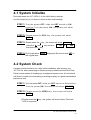
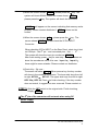
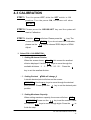
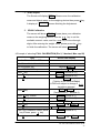
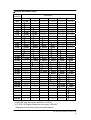
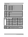
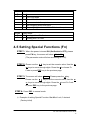
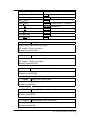
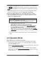
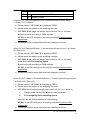
1
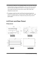
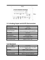
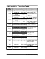
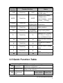
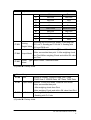
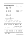
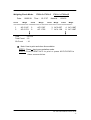
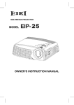
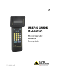
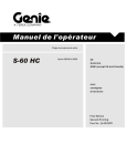
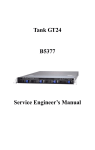
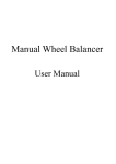
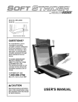
CHAPTER 1 INTRODUCTION JIF-2001A WEIGHING INDICATOR 1 1-1 Welcome The JIF-2001 weighing indicator is the product of years of design, development, and in-field testing. It is a stable weighing indicator with various functions. Additional weighing check function enables JIF-2001 to fulfill the need of users. Interfaces are easy to connect so that users can perform various applications. With sincere gratitude for your using our products, once any question or problems occurred, please contact us or our distributors immediately for further services. 1-2 Features JIF-2001 Weighing Indicator has following built-in designs: Watchdog virtually eliminates malfunctions which associated with computerized equipment. Fully digital calibration makes settings easier: Full Calibration, ZERO adjustment, and SPAN adjustment. Drive up to 8 parallel connecting load cells(350Ω ). 1/15,000 displayed resolution, DC Input 1/12,000. (JIF-2001AH displayed resolution up to 1/60,000 depend on load cell quality). 8k bytes SRAM with Li-battery back-up. Information will not disappear even power failure. 100 coded Special Function setting (Fn): Hi, Lo, Material, Total Count, Pre-Finish Count, Standard Count, and Pre-tare. The settings of function and weighing parameters are all stored in the EEPROM, with storage duration over 40 years. With weighing check function, and the buzzer inside, it can provide users with more applications. JIF-2001A WEIGHING INDICATOR 2 Users can adjust the intensity of digits filter to avoid mechanical vibration which caused by external environments to achieve high-speed and accurate measurement. 8 set of control I/O Connector, enable more applications (Can connect to photo cell). 20mA Current Loop can connect to large-size LED Indicator. Printing and output data automatically through function preset. Optional RS-232: bi-dimensional RS-232 can be connected to computer, monitor or other peripheral. Optional Centronic: An interface connected to printer or mini printers. 1-3 System Function Introduction RE-INITIALIZE THE SYSTEM: Turn the power OFF; slide the SET switch to ON position; Turn the power ON, the screen will show SELECT . Please press the ESC key, the system will start the re-initialize process.(4-1) SYSTEM CHECK: Turn the power OFF; slide the SET switch to ON position; Turn the power ON, the screen will show SELECT . Please press the ZERO key, the system will start the SYSTEM CHECK process. The screen will start the following functions. (4-2) ※ ※ ※ ※ CHECK DISPLAY CHECK MEMORY CHECK KEY CHECK INPUT JIF-2001A WEIGHING INDICATOR 3 FUNCTION SETTING: Turn the power OFF; slide the SET switch to ON position; Turn the power ON, the screen will show SELECT . Please press the ZERO key, the system will start the FUNCTION SETTING process. The screen will display following function: (4-4) ※ ※ ※ ※ FUNCTION (F000 ∼ F018) SERIAL INTERFACE (F200 ∼ F204) PRINTER (F300 ∼ F305) CURRENT LOOP (FC00 ∼ FC02) CALIBRATION: Turn the power OFF; slide the SET switch to ON position; Turn the power ON, the screen will show SELECT . Please press the GROSS/NET key and the screen will display following function: (4-3) ※ F-CAL (Full-step calibration) For JIF-2001: ※ ※ Adj. ZERO (Calibration: ZERO Adjustment) Adj. SPAN (Calibration: SPAN Adjustment) For JIF-2001 AH: ※ D-CAL (Digital calibration) SPECIAL FUNCTION SETTING: When the power is turned ON (Set Switch is OFF), press FN key. The screen will display following functions: (4-5) ※ Set Hi ※ ※ ※ ※ ※ ※ Set Lo Mater T. Count S. Count P. F. Count P. tare ★★★★See more details in “CHAPTER 4”★★★★ JIF-2001A WEIGHING INDICATOR 4 CHAPTER 2 INSTALLATION JIF-2001A WEIGHING INDICATOR 5 2-1 Best Conditions For Use When installing and wire connecting on JIF-2001A, please follow the points and guide for preventing any abnormal situation occurred. Before connecting the Electric Power Supply, please identify the input Electric voltage type is AC 110V, AC 220V (both for JIF-2001A), or DC input (JIF-2001A) . The Grounding Wire shall be properly connected . The Operation Temperature shall range within -10℃ ~ 45℃ , please DO not install in any place of direct sun-light . The input power shall be AC 110V or AC 220V±10%, if the Electric Power Supply is not stable or the interference signal exists, that may cause uncertain actuation or reaction, even damages . Therefore, please utilize Electric Power Supply Stabilizer of adequate capacity. 2-2 Power Supply Connecting Open the case, there is a jumper﹝S1﹞near the (TOPMARK) E3HKWA02 TOPMARK transformer located at the PCB board, please insert a short-circuit pin to the available side. 8506072F AC input voltage 110V S1 AC input voltage 220V S1 110V 110V 220V 220V S1 110V 220V JIF-2001A WEIGHING INDICATOR 6 2-3 DC Power Supply Connecting ※DC 12V Input through 3 pin Input in the rear panel. ※Or Input DC 12V through ADAPTOR. 2-4 Connecting the Load Cell Do not plug in your power cable until you have completely connected the load cell. Screw Signal 1 Positive Excitation Voltage, (EXC+) 2 Positive Sense Voltage, (SEN+) 3 Negative Sense Voltage, (SEN-) 4 Negative Excitation Voltage, (EXC-) 5 Positive Signal Voltage, (SIG+) 6 Negative Signal Voltage, (SIG-) 7 Shield, (SHD) ※ It could be dangerous by using improper battery or wrong connection of battery JIF-2001A WEIGHING INDICATOR 7 ※To connect your load cell to the weighing Indicator use a six-wire cable with shield-connect the wires as indicated above. If the JIF-2001A is located near the Load Cells (Within five meters or a few yards) you may use a 4-wire cable with shield, but first connect screws 1&2 and 3&4 with independent jumper leads. ※The analogue output from the Load Cell and input/output signals are sensitive to electrical noise. Do not bind these cables together as it could result in cross-talk interference. Please also keep them away from AC power cables. 2-5 Front and Rear Panel Dimensions Front Panel Rear Panel Side View For Mounting JIF-2001A WEIGHING INDICATOR 8 CHAPTER 3 SPECIFICATIONS JIF-2001A WEIGHING INDICATOR 9 3-1 Analog Input and A/D Conversion Type JIF-2001A Input Sensitivity ZERO Adjustment Range Load-Cell Excitation ≧0.6uV/D 0.6mV ~24mV DC12V±5,300mA, Remote Sensing. Can be connected up to 8 load cells(350Ω) Non-Linearity 0.01 % F.S Input Noise ±0.3uV p-p Input Impedance A/D Conversion Method A/D Resolution A/D Conversion Rate 10MΩor above Double Integral System 180,000 Approx. 8 Times/Sec. 3-2 General Type Power Requirements Net weight Operation Temperature Maximum Humidity Physical Dimensions JIF-2001A AC 110V or AC220V ±10%,50/60Hz Approx. 25VA Approx. 3.2 kg﹝7.054 lb﹞ -10∼ 45℃ 85%﹝non-condensing﹞ 240 (D) ×190 (W) ×104(H)mm JIF-2001A WEIGHING INDICATOR 10 3-3 Front Panel Description ◎ DIGITAL SECTION Main Display﹝Green Tube﹞ Minimum Division Maximum Display Under ZERO Indicator 〝ZERO〞 ▼Annunciator 〝MD〞 ▼Annunciator 7-segment,7-digit display, VFD screen with a 13mm character size, displays the weight. ×1、×2、×5、×10、×20、×50 +750450 〝—〞minus sign Center of Zero Motion Detection (Unstable) 〝GROSS〞▼Annunciator Gross Mode 〝NET〞▼Annunciator Net Mode 〝TARE ENTERED〞 ▼Annunciator Tare has been entered 〝ACCUM〞▼Annunciator Display Accumulator or Material 〝COUNT〞▼Annunciator Number of Times Optional unit╱”Hi” Output Status LED 〝 ╱Hi〞 ●Annunciator 〝kg ╱OK〞●Annunciator 〝lb ╱Lo〞 ●Annunciator 〝ZERO ╱←〞Key Annunciator Kilograms Displayed╱”OK” Within standard range Ponds Displayed ╱”Lo” Output Status LED Annunciator Stable ZERO/Left shift key 〝TARE╱↑〞Key TARE’s when stable-in Net, display ZERO /Increase the number 〝GROSS、NET╱↓〞Key Changes from “Gross” to “ Net” and vise versa/Decrease the number 〝TARE CLEAR╱→〞Key Tare is cleared/Right shift Key 〝PRINT╱ACC〞Key Data will send one time/Print 〝ACC╱CLEAR〞Key Accumulation Display Accumulator/Clear Accumulation 〝UNIT〞Key Changes from kg to lb and vise versa. 〝Fn〞Key Special Function Setting Change Mode/Enter Key (Normal =>ACC =>COUNT) 〝MODE╱↵〞Key 〝STANDBY╱ESC Key Standby Status/ESC JIF-2001A WEIGHING INDICATOR 11 3-4 Panel Key Function Table Key Function Function Position Panel Key Status JIF-2001A returns to the ZERO Pin1 + Pin 9 center of ZERO if the weight value within F003 OP-02 range. Z Cr Lf (Command Mode) V ZERO ON Control I / O ZERO JIF-2001A switches to Control I / O Pin 2 + Pin 9 NET mode, ZERO’s the display and stores the OP-02 TARE weight in Memory. T Cr Lf (Command Mode) V TARE ENTER ON Panel Key TARE TARE CLEAR Panel Key Control I / O Panel Key GROSS Control I / O OP-02 (Command Mode) Panel Key NET PRINT Control I / O OP-02 (Command Key) TARE CLEAR Clear TARE Value Pin4 + Pin 9 V TARE ENTER OFF GROSS / NET Pin3 + Pin 9 Shift to GROSS Mode V GROSS ON G Cr Lf GROSS / NET Pin3 + Pin9 Shift to NET mode V NET ON N Cr Lf Panel Key PRINT / ACC Control I / O Pin 6 + Pin 9 Panel Key ACC TARE Control I / O Print or Output latest Data PRINT / ACC Print Accumulation Value Please use MODE key to Pin 5 + Pin 9 switch to T ACC ACC Panel Key Print Accumulation ACC / CLEAR Please use MODE key to swift to TACC CLEAR Panel Key ACC / CLEAR Clear Accumulation and Count JIF-2001A WEIGHING INDICATOR 12 Key Function UNIT Function Position Panel Key Status UNIT Changes from “Kg” to “Lb” and vise versa. MODE Changes from Display tWeight Value tAccumulation、V(ACC) tCount、VCOUNT MODE Panel Key STANDBY Panel Key STANDBY/ Standby Mode will Pause OPERATE/ESC all operation. OPERATE Panel Key STANDBY/ Starts operation. OPERATE/ESC Panel Key STANDBY/ Escape setting Mode OPERATE/ESC ESC Panel Key Fn Setting Hi, Lo, T. Count, OK. Count, C. Finish, P. tare, and Material Code. → Panel Key → Right shift key in setting Mode ← Panel Key ← Left shift key in setting Mode ↑ Panel Key ↑ Increase value in setting mode ↓ Panel Key ↓ Decrease value in setting mode Panel Key Enter key in setting mode Fn 3-5 Quick Function Table ◎ WEIGHT FUNCTION TABLE Decimal Point 0No Decimal 11 Decimal 22 Decimal F 000 Adjustment 3 Decimal 44 Decimal 0Optional unit Kilogram 2Pound F 001 Displayed Unit 3Gram 4Ton 5Ounce Display Display Update Digital Filter F 002 Update/Digital Filter JIF-2001A WEIGHING INDICATOR 13 41 4 times/Sec. 1 stage filter 42 4 times/Sec. 2 stage filter 43 4 times/Sec. 3 stage filter 44 4 times/Sec. 4 stage filter 81 8 times/Sec. 1 stage filter ● 82 8 times/Sec. 2 stage filter 83 8 times/Sec. 3 stage filter 84 8 times/Sec. 4 stage filter ±10%2±20% of weighing platform full capacity F 003 Set Zero Range Motion 1 SEC 1 DIV ∼ 2 SEC 8 DIV ; 16 Steps F 004 Detection Automatic 2 SEC 4.0 DIV; 16 Steps F 005 ZERO Tracking 1 SEC 0.5 DIV ∼ Compensation ZERO & TARE ZERO & TARE keys only work when display is F 006 keys Availability STABLE 2always work TARE Key If the GROSS is Negative (-), TARE key does not F 007 Availability work.1TARE key always work Buzzer OFF 1Work when OK 2Work when Hi or Lo F 008 Availability When Checking F 009 Operation Mode Normal Mode 2Weighing Check Mode Accumulation Not Work 1Auto Accumulate when weight stable F 010 Availability 2 Manual mode 3Accumulate only on OK values Weighing Check Stable 2Photocell detect 3 Stable + Photocell F 011 Command detect Mode Selectable (enter weight) F 012 NET Band Weighing 14 Times/Sec 8 Times/Sec 3 16 Times/Sec F 013 checking Sampling Not input 1Input Pre-set TARE value by TARE Per-set TARE key 2Input Pre-set TARE value when turning on the F 014 input power or changing Fn code. Order in 7 digits 0 No order ① Hi ② Lo ③ Material Code ④Total Fn function F 015 order Count ⑤ Standard Count ⑥ Preset Finish Count ⑦ Preset TARE (Initial: 1234567) Unit conversion Input 6 digit unit conversion rate F 016 rate 0 None ① 1 Digit ② 2 Digit ③ 3 Digit ④ 4 Digit Unit digit F 017 displayed ⑤ 5 Digit ⑥ 6 Digit 0 Optional unit ① Kilogram ② Lb ③ Gram ④ F 018 Optional Unit Ton ⑤ Ounce ※Symbol : Factory Initial. ※Symbol: Checking mode related parameters. JIF-2001A WEIGHING INDICATOR 14 ◎ SERIAL ﹝RS-232﹞ OP-02 F 200 Baud Rate 11200 BPS 2400 BPS 34800 BPS 49600 BPS 0 None Even Parity 2Odd Parity F 201 Parity Output Same as display 2Gross data 3NET data F 202 Data 4TARE data 5 Gross data, NET data, TARE data Fn Code 0Sending without code number number Sending with code number Weight Same as display 2Gross data 3NET data value 4TARE data 5 Gross data, NET data, TARE data Material Sending without code number Code 1Sending with code number Total Count Standard Count Checking Mode Sending without Sending without Sending without T. Count S. Count Check Mode Sending without Sending without Sending with 1 T. Count S. Count Check Mode Sending without Sending with S. Sending without 2 T. Count Count Check Mode Weighing Sending without Sending with S. Sending with 3 Check by T. Count Count Check Mode Counts Sending with T. Sending without Sending without 4 Count S. Count Check Mode Sending with T. Sending without Sending with 5 Count S. Count Check Mode Sending with T. Sending with S. Sending without ⑥ Count Count Check Mode Sending with T. Sending with S. Sending with 7 Count Count Check Mode Accumulati Sending without Accumulation 1Sending with on Accumulation Sending Sending with the same as display 2Sending with F001 unit 3 Sending as F018 unit 4 Sending with F001 and F 203 Weight Value F018 unit Stream 2Auto print Mode 3Manual Print Mode 4After accumulate then print 5 After weighing check then Print Output F 204 6After weighing Check and within OK value then Print Mode ⑦Command Mode ※Symbol : Factory Initial. JIF-2001A WEIGHING INDICATOR 15 ◎ PRINTER OP-03 F 300 Date, Time Setting Year. month, day, hour, minute, second F 301 Output Data Date/Time Fn Code/ Material Code Weighing Check by Counts Date Time 0 Not Print Not Print 1 Not Print Print on Top 2 Not Print Print on All 3 Print on Top Not Print ❹ 5 Print on Top Print on Top Print on Top Print on All ⑥ Print on All Not Print 7 Print on All Print on Top ➇ Print on All Print on All Fn code Material code 0 Not Print Not Print 1 Not Print Print on Top 2 Not Print Print on All 3 Print on Top Not Print ❹ 5 Print on Top Print on Top Print on Top Print on All ⑥ 7 Print on All Not Print Print on All Print on Top ➇ Print on All Print on All Total Count Standard Count Checking Mode Not Print Not Print Not Print 1 Not Print Not Print Print 2 Not Print Print Not Print 3 Not Print Print Print 4 Print Not Print Not Print 5 Print Not Print Print Print Print Not Print ⑥ 7 Print Print Print Same as Display 2GROSS Data 3NET Data Weight Value 4TARE Data 5 GROSS Data, NET Data, TARE Data ⑥ GROSS Data, TARE Data, NET Data Unit 0 Not Print Print on Top 2Print on all JIF-2001A WEIGHING INDICATOR 16 F 302 Output Accumulation Data Date Time 0 Not Print Not Print 1 Not Print Print 2 Print Not Print ➌ Print Print Total Count Standard Count Not Print Not Print 1 Not Print Print 2 Print Not Print 3 Print Print Sending with the same as display 2Sending with F001 unit 3 Sending as F018 unit 4 Sending with F 303 Weight Value F001 and F018 unit Printing 1Not Print 2Auto print Mode ➌Manual Print Mode 4After accumulate then print 5 After weighing check F 304 Output Mode then Print6After weighing Check and within OK value then Print F 305 Printer Type Select ※Symbol MINI Printer -2Normal Printer : Factory Initial. ◎ Current Loop F C00 Data Same as Display 2GROSS Data 3NET Data 4TARE Data 5 GROSS Data, NET Data, TARE Data F C01 Output Mode Stream 2Auto print Mode 3Manual Print Mode 4After accumulate then print 5 After weighing check then Print 6After weighing Check and within OK value then Print F C02 Fn Code Sending without Fn Code 1 Sending with Fn Code ※Symbol : Factory Initial. JIF-2001A WEIGHING INDICATOR 17 ◎ Fn [Setting Special Functions] Set Hi Setting Over limit Value Set Lo Setting Under Limit Value Mater Setting Material Code T. Count Setting Total Count Value S. Count Setting OK (Standard) Count Value P. F. Count Setting Preset Finish Count alert P. tare Preset TARE value JIF-2001A WEIGHING INDICATOR 18 CHAPTER 4 SYSTEM FUNCTIONS JIF-2001A WEIGHING INDICATOR 19 4-1 System Initialize Re-install resets the JIF-2001A to the initial factory settings. Use Re-install only if you want to return to their initial settings. STEP 1: Turn the power OFF; slide the SET switch to ON position; Turn the power ON, the screen will show SELECT . STEP 2: Please press the ESC key, the screen will show INIT . STEP 3: Please press the ↵ key , the screen will show Using the ↑ and ↓ key move to﹝ no or no . Yes ﹞, then press the ↵ key. STEP 4: End of operation, END displayed. Be sure to slide SET to the original side. 4-2 System Check A system check should be run: after initial installation, after moving your JIF-2001A, after connecting or disconnecting an attachment from the Rear Panel and as means of locating any unexplained system error. An occasional self-check to make sure everything is working properly is a good maintenance practice as well. STEP 1: Turn the power OFF; slide the SET switch to ON position; Turn the power ON, the screen will show SELECT . STEP 2: Please press the ZERO key, the screen will show CHEC . ※Please press the ↵ key , the system will check Green Tube and LED in sequence. JIF-2001A WEIGHING INDICATOR 20 ※When the screen shows Sran , please press the ↵ key. The system will check SRAM. When the screen shows EE , please press the ↵ key. The system will check the EEPROM. PASS will appear on the screen indicating that memory works properly. Please contact distributor if screen. ※When the screen shows I-O FAIL shows on the , please press the ↵ key . The screen shows INPUT 0 . Please check the 25 Pin INPUT Connector. When checking 25 Pin INPUT on the Rear Panel, short-circuit test on COM pin﹝the 9th pin﹞and connected pins﹝first ∼ 8th﹞. The screen will show the input pin number as INPUT X . After finish testing, press ↵ key for next step;If any pin does not show the accordance value of its own﹝Input 1∼ Input 8﹞, there might be some mistake. Please contact our distributor. ※Check Key﹝By user﹞ The screen will show 〔 〕. When press a key, the key number will show in the middle of the screen. The lower side keys from left to right: KEY 01∼ KEY 07. The upper side keys from left to right: KEY 08∼ KEY 09, Press ↵ to finish checking. If the key number does not match, it suggests an error occurred. Please contact us. STEP 3: Slide the SET switch to the original side. Finish checking, display END . ※The 8th pin of the connector will not work when using DC power supply. JIF-2001A WEIGHING INDICATOR 21 4-3 CALIBRATION STEP 1: Turn the power OFF; slide the SET switch to ON position; Turn the power ON, the screen will show SELECT . STEP 2: Please press the GROSS/NET key and the system will start to Calibration. STEP 3: A twinkle CAL will show. Please press the ↵ key. The screen will show F-CAL . If you do not need Full Calibration, please use the ↑↓ keys to choose ZERO Adjust or SPAN Adjust. 1. Select FULL CALIBRATION: ﹝1﹞Setting Minimum Division When the screen shows di 01 , this means the smallest division displayed. Use the ↑↓ keys to move through the available divisions.﹝1、2、5、10、20、50﹞. Press the ↵ key to set the smallest division. ﹝2﹞Setting Decimal (F000 will change) A twinkle decimal point will show on the screen: d0000.000 .Use the←→ keys to move through the decimal point position. Please press the ↵ key to set the decimal point position. ﹝3﹞Setting Maximum Capacity When setting maximum capacity, the screen will show CAP . → C000.000 . Please use the ↑↓ key to set the numeric value and use the ←→ keys to move through digits. Press the ↵ to finish the step. JIF-2001A WEIGHING INDICATOR 22 ﹝4﹞ZERO Adjust The Screen will display ZERO . Please move the calibration mass and objects away on the weighing device then press ↵ key. A display of means finishing the Adjustment. ....... ﹝5﹞SPAN Calibration The screen will show SPAN . Please place your calibration mass on the weighing device. Use the ↑↓ key to set the available numeric value, and the ←→ key to move through digits. After entering the weight value, please press the ↵ key to finish the calibration. The screen will show ........ ※Example of selecting FULL CALIBRATION (Div 2, 3 decimal, Max cap.20) Key Screen will display Turn the Power Switch OFF Slide Set switch to the set side Turn the power ON Twinkle SELECT Press GROSS/NET key Press ↵ key Press ↑ key Press ↵ key Twinkle CAL di 01(Twinkle at 01) di 02(Twinkle at 02) 010.000 (Twinkle at the Decimal Point) ※F000 will subject to change if ←→ keys been pressed Press ↵ key CAP →010.000 (Twinkle at the 3rd decimal 0) Press ← key 4 times 010.000(Twinkle at 1) Press ↑ key 020.000(Twinkle at 2) Press ↵ key Press ↵ key Press ↵ key ZERO …… → SPAN 000.000(Twinkle at the 3rd Decimal) Place 1kg Calibration Mass, press ← key 3 times, press ↑ key 001.000(Twinkle at 1) Press ↵ key …… → End JIF-2001A WEIGHING INDICATOR 23 2. Select Fine ZERO Adjust When the screen shows Adj ZERO. Please move the calibration mass and objects away on the Weighing device then press ↵ key. If the screen shows . . . . . . ., then Fine ZERO Adjust is finished. ※ZERO Adjust only used to perform minor zero drifting. Please select Full Calibration if there is greater difference. 3. Select Fine SPAN Adjust: ﹝1﹞When the screen shows Adj SPAN. Place your calibration mass on the weighing device and press ↵ key. ﹝2﹞Use the ↑↓ key to available value and press ↵ key. ※Fine SPAN Adjust only used to perform minor zero drifting. Please select Full Calibration if there is greater difference. STEP 4 : The screen will show END . Slide the SET switch to the original side. JIF-2001A WEIGHING INDICATOR 24 ◎Calibration Errors C. Err 1:The resolution exceeds 1:15,000.(1 : 60,000 for JIF-2001 A) ÖChange the minimum division and maximum capacity within 1/ 15,000.Resolution ratio= Minimum division/maximum capacity C. Err 2:The load cell output is too large at ZERO calibration. ÖAdd an additional resistor(50kΩ∼500KΩ) between EXC+ and SIG—. C. Err 3:The load cell output is too small at ZERO calibration. Ö Add an additional resistor(50kΩ∼ 500KΩ) between EXC+ and SIG+. C. Err 4:The calibration mass has been mistakenly entered as a value greater than the maximum capacity. ÖPlease reduce the weight of calibration mass, and re-enter the weight value. C. Err 5: The calibration mass has been wrongly entered zero or it is smaller than the minimum capacity. ÖPlease increase the weight of calibration mass, and re-enter the weight value. C. Err 6: The load cell output is too low. ÖReplace your load cell with a more sensitive one or adjust the minimum division. C. Err 7: The load cell signal pins are reversed, or the load cell output voltage is too low. ÖCheck the load cell connections if reversed or load cell failure. C. Err 8: The load cell output voltage at maximum capacity is too high. Ö Check the load cell specification or load cell failure. C. Err 9: The maximum, capacity has been wrongly entered as a value smaller than 300. ÖCheck Resolution Table. C. Err 10: The maximum, capacity has been wrongly entered as a value greater than 750,000. Ö Check the load cell specification or load cell failure. JIF-2001A WEIGHING INDICATOR 25 ◎Display Resolution Table Maximum Capacity Resolution 1 Min. Div. 2 Min. Div. 5 Min. Div. 10Min.Div. 20Min.Div. 50Min.Div. 300 400 500 600 800 1,000 1,200 1,500 2,000 2,500 3,000 4,000 5,000 6,000 8,000 10,000 12,000 15,000 20,000 25,000 30,000 40,000 50,000 60,000 80,000 100,000 120,000 150,000 200,000 250,000 300,000 400,000 500,000 600,000 1/300 1/400 1/500 1/600 1/800 1/1000 1/1200 1/1500 1/2000 1/2500 1/3000 1/4000 1/5000 1/6000 1/8000 1/10000 1/12000 1/15000 --------------------------------------------------------------------------------------------------------------------------------------------------------------------------------- ---------------------------------1/300 1/400 1/500 1/600 1/800 1/1000 1/1200 1/1500 1/2000 1/2500 1/3000 1/4000 1/5000 1/6000 1/8000 1/10000 1/12500 1/15000 ------------------------------------------------------------------------------------------------------------------------------------------------ -----------------------------------------------------------------------------1/300 1/400 1/500 1/600 1/800 1/1000 1/1200 1/1500 1/2000 1/2500 1/3000 1/4000 1/5000 1/6000 1/8000 1/10000 1/12000 --------------------------------------------------------------------------------------------------------------- --------------------------------------------------------------------------------------------------------------1/300 1/400 1/500 1/600 1/800 1/1000 1/1200 1/1500 1/2000 1/2500 1/3000 1/4000 1/5000 1/6000 1/8000 1/10000 1/12000 1/15000 ------------------------------------------------------------------- -----------------------------------------------------------------------------------------------------------------------------------------------1/300 1/400 1/500 1/600 1/800 1/1000 1/1200 1/1500 1/2000 1/2500 1/3000 1/4000 1/5000 1/6000 1/8000 1/10000 1/12500 1/15000 ---------------------------------- -------------------------------------------------------------------------------------------------------------------------------------------------------------------------------------------1/300 1/400 1/500 1/600 1/800 1/1000 1/1200 1/1500 1/2000 1/2500 1/3000 1/4000 1/5000 1/6000 1/8000 1/10000 1/12000 700,000 750,000 ----------------------- ----------------------- ----------------------- ----------------------- ----------------------- 1/14000 1/15000 ☆2001A/DC type maximum resolution 1/12000 ☆JIF-2001 A Display Resolution can reach 1/60,000. (Depends on load cell quality and performance). JIF-2001A WEIGHING INDICATOR 26 4-4 Function STEP 1: Turn the Power Switch OFF on the Rear Panel, Slide the SET switch to the set side. Please turn on the power, the screen will show SELECT . STEP 2 : Please press the TARE key, the screen will show Func . The system will start function setting. STEP 3: Use the ↑↓ keys to move through the function category (F000, F100, F200 or F300 OR FC00). Then press the ↵ Key. Use the ↑↓ keys to choose specific function category (F000 ~ F018, F200 ~ F204, F300 ~ F305, or FC00 ~ FC02 ). Press the ↵ key to choose specific function. In each function, please use ↑↓ and ←→ keys to set function value(see each function chart below). If you want to return to previous function category, please press ESC key, or press ↵ key to enter. ※ If any errors occurred ( F err ), please check if each setting value within effective range. ※ note:● or Indicates initial factory setting. STEP 4: When you have finished changing the Function setting, slide SET Switch to the original side. The screen will show END . JIF-2001A WEIGHING INDICATOR 27 ◎ Setting Function F000 Decimal Point Adjustment ● 0 No Decimal 1234567 1 1 Decimal 123456.7 2 2 Decimal 12345.67 3 3 Decimal 1234.567 4 4 Decimal 123.4567 F001 Displayed Unit ● F 002 0 Optional unit 1 Kilogram 2 Pound 3 Gram 4 Ton 5 Ounce Display Update/ Digital Filter 41 ● Display Update Digital Filter 4 times/Sec. 1 stage filter 42 4 times/Sec. 2 stage filter 43 4 times/Sec. 3 stage filter 44 4 times/Sec. 4 stage filter 81 8 times/Sec. 1 stage filter 82 8 times/Sec. 2 stage filter 83 8 times/Sec. 3 stage filter 84 8 times/Sec. 4 stage filter F003 Set ZERO Range ● ±10% of weighing platform Full Capacity 1 ±20% of weighing platform Full Capacity 2 JIF-2001A WEIGHING INDICATOR 28 F004 Motion Detection ● F005 0 Stable 11 1 SEC 1 DIV 12 1 SEC 2 DIV 13 1 SEC 3 DIV 14 1 SEC 4 DIV 15 1 SEC 5 DIV 16 1 SEC 6 DIV 17 1 SEC 7 DIV 18 1 SEC 8 DIV 21 2 SEC 1 DIV 22 2 SEC 2 DIV 23 2 SEC 3 DIV 24 2 SEC 4 DIV 25 2 SEC 5 DIV 26 2 SEC 6 DIV 27 2 SEC 7 DIV 28 2 SEC 8 DIV Automatic ZERO Tracking Compensation 0 Invalid 11 1 SEC 0.5 DIV 12 1 SEC 1.0 DIV 13 1 SEC 1.5 DIV 14 1 SEC 2.0 DIV 15 1 SEC 2.5 DIV 16 1 SEC 3.0 DIV 17 1 SEC 3.5 DIV 18 1 SEC 4.0 DIV 21 2 SEC 0.5 DIV 22 2 SEC 1.0 DIV 23 2 SEC 1.5 DIV ● 24 2 SEC 2.0 DIV 25 2 SEC 2.5 DIV 26 2 SEC 3.0 DIV 27 2 SEC 3.5 DIV 28 2 SEC 4.0 DIV JIF-2001A WEIGHING INDICATOR 29 F006 ● F007 ● ZERO & TARE keys Availability ZERO & TARE keys only work when display is 1 STABLE 2 ZERO & TARE keys always work TARE key Availability 1 If the GROSS is negative, TARE key does not work 2 TARE key always work F008 Buzzer Availability when Checking (Related to Check Mode) 0 OFF ● 1 Work when OK 2 Work when Hi or Lo F009 Operation Mode (Related to Check Mode) ● Normal Mode- Buzzer OFF 1 2 Weighing Check F010 Accumulation Availability ● 0 Not Work (Related to Check Mode) 1 Auto Accumulate when weight stable 2 Manual Mode 3 Accumulate only on OK values ※See 4-9 for details. F011 Weighing Check Command Mode (Related to Check Mode) ● 1 Stable 2 Photo cell detect 3 Stable + Photo cell detect ※See 4-6 for details. F012 NET Band (Related to Check Mode) Selectable (Enter Weight) ●Factory Initial 000.000 JIF-2001A WEIGHING INDICATOR 30 F013 Weighing Checking Sampling ● 4 4 Times/Sec 8 8 Times/Sec (Related to Check Mode) 16 16 Times/Sec ※See 4-6 for details. F014 Pre-set TARE Input ● 0 Not Input 1 Input Pre-set TARE value by TARE key 2 Input Pre-set TARE value when turning on the power or changing Fn code Not input 1Input Pre-set TARE value by TARE key 2Input Pre-set TARE value when turning on the power or changing Fn code. F015 Fn function Order (Related to Check Mode) Order in 7 digits 0No order ①Hi ②Lo ③Material Code ④Total Count ⑤Standard Count ⑥ Preset Finish Count ⑦Preset TARE (Initial: 1234567) ☛If the order sets at: 1234567, the screen will show in order as follows: Hi →Lo→----→P. TARE. (Please refer to 4-5) F016 Optional Unit conversion rate Input 6 Digit unit conversion rate F017 Unit Digit displayed ● 0 None 1 1 Digit 2 2 Digit 3 3 Digit 4 4 Digit 5 5 Digit 6 6 Digit JIF-2001A WEIGHING INDICATOR 31 F018 Optional Unit ● 0 Optional unit 1 Kilogram 2 Lb 3 Gram 4 Ton 5 Ounce ◎SERIAL ﹝RS-232﹞ F200 Baud Rate ● 1 1200 bps 2 2400 bps 3 4800 bps 4 9600 bps F201 Parity ● 0 None 1 Even 2 Odd F 202 Output Data Same as display 2Gross data 3NET data 4TARE data 5 Gross data, NET data, TARE data Fn Code number 0Sending without code number Sending with code number Weight value Same as display 2Gross data 3NET data 4TARE data 5 Gross data, NET data, TARE data Material Code Sending without code number 1Sending with code number Weighing Check by Counts Total Count Sending without T. Count Sending 1 without T. Count Sending 2 without T. Count Checking Mode Sending Sending without without S. Count Check Mode Standard Count Sending without Sending with S. Count Check Mode Sending Sending with S. without Count Check Mode JIF-2001A WEIGHING INDICATOR 32 Sending 3 without T. Count Sending Sending without without S. Count Check Mode Sending with Sending without Sending with 5 T. Count S. Count Check Mode Sending Sending with Sending with S. without ⑥ T. Count Count Check Mode Sending with Sending with S. Sending with 7 T. Count Count Check Mode Sending without Accumulation Accumulation 1Sending with Accumulation : means factory initial 4 ※ Sending with S. Sending with Count Check Mode F203 ● Sending with T. Count Sending Weight Value 1 Sending with the same as display 2 Sending with F001 unit 3 Sending as F018 unit 4 Sending with F001 and F018 unit F204 ● Output Mode 1 Stream 2 Auto Print Mode 3 Manual Print Mode 4 After accumulate then print 5 After weighing check then print 6 After weighing check and within OK value then print 7 Command Mode ◎PRINTER F300 Date, Time Year/ Month /day hour:minute:second XX/ XX / XX XX: XX : XX JIF-2001A WEIGHING INDICATOR 33 F301 Output Data Date/Time Fn Code/ Material Code Weighing Check by Counts Date Time 0 Not Print Not Print 1 Not Print Print on Top 2 Not Print Print on All 3 Print on Top Not Print ❹ 5 Print on Top Print on Top Print on Top Print on All ⑥ 7 Print on All Not Print Print on All Print on Top ➇ Print on All Print on All Fn code Material code 0 Not Print Not Print 1 Not Print Print on Top 2 Not Print Print on All 3 Print on Top Not Print ❹ Print on Top Print on Top 5 Print on Top Print on All ⑥ 7 Print on All Not Print Print on All Print on Top ➇ Print on All Print on All Total Count Standard Count Checking Mode Not Print Not Print Not Print 1 Not Print Not Print Print 2 Not Print Print Not Print 3 Not Print Print Print 4 Print Not Print Not Print 5 Print Not Print Print ⑥ Print Print Not Print 7 Print Print Print Same as Display 2GROSS Data 3NET Data 4TARE Data 5 GROSS Data, NET Data, TARE Weight Value Data ⑥ GROSS Data, TARE Data, NET Data Unit 0 Not Print Print on Top 2Print on all ※ : means factory initial JIF-2001A WEIGHING INDICATOR 34 F 302 Output Accumulation Data ※ Date Time 0 Not Print Not Print 1 Not Print Print 2 Print Not Print ➌ Print Total Count Not Print Print Standard Count Not Print 1 Not Print Print 2 Print Not Print 3 Print Print : means factory initial F303 Sending Weight Value 1 Sending with the same as display 2 Sending with F001 unit ● 3 Sending as F018 unit 4 Sending with F001 and F018 unit F304 Output Mode 0 No output 1 Stream 2 Manual Print Mode ● 3 After accumulate then print 4 After weighing check then print 5 After weighing check and within OK value then print F 305 ● Printer Type Select 1 MINI Printer 2 Normal Printer ◎ Current Loop FC00 ● Current Loop Data 1 Same as display 2 GROSS Data 3 NET Data 4 TARE Data 5 GROSS, NET and TARE Data JIF-2001A WEIGHING INDICATOR 35 FC01 ● Output Mode 1 Stream 2 Auto Print Mode 3 Manual Print Mode 4 After accumulate then print 5 After weighing check then print 6 After weighing check and within OK value then print FC02 ● Output Mode 0 Sending without Fn Code 1 Sending with Fn Code 4-5 Setting Special Functions (Fn) STEP 1: When the power is turned ON (Set Switch is OFF), please press FN key, the screen will show Code 00 (The parameter order will show according to F015). STEP 2: Please use the ↑↓ key to set the numeric value, Use the ← → keys to move through digits. Press the ↵ to choose Fn Code or press ESC key to the previous page. STEP 3: The screen will show Hi . Please press the ↵ key. Please use the ↑↓ key to set the numeric value, Use the ← → keys to move through digits. Press the ↵ to set Fn Code or press ESC key to the previous page. STEP 4: Press ESC to normal mode. ※ Example of setting Special Function: Set Hi at 1unit; 3 decimal (Factory initial) JIF-2001A WEIGHING INDICATOR 36 Key Screen will display Turn the Power Switch ON 0.000 Press Fn key Code 00 Press ↵ key Hi Press ↵ key 000.000(Twinkle at the 3rd Decimal) Press ← key three times 000.000(Twinkle at 0) Press ↑ key 001.000 Press ↵ key Lo Press ESC key Code 00 Press ESC key 0.000 Set Hi Setting Over Limit Value Please Enter 6 digit Over Limit Value NET weight > Over Limit Value ●Factory Initial 000.000 Set Lo Setting Under Limit Value Please Enter 6 digit Under Limit Value NET weight < Under Limit Value ●Factory Initial 000.000 Mater Setting Material Ordinal Number Please Enter 6 digit material Ordinal Number ●Factory Initial 000000 T. Count Setting Total Count Value Please Enter 4 digit Beginning Total Count Value ●Factory Initial 0000 S. Count Setting OK (Standard) Count Value Please Enter 4 digit S. Count Value ●Factory Initial 0000 P. F. Finish Setting Preset Finish count alert Please Enter 4 digit Preset Finish count alert value ●Factory Initial 0000 JIF-2001A WEIGHING INDICATOR 37 ※If you wish to set weight time at 1,000 times, please set P. F. Finish alert at 1000 . P. F. Finish will accumulate once when the object been read stable (As the MD ▼Annunicator Vanished). As long as the accumulated value reached 1000 counts, the screen will show blinking digits. Please press ACC/CLEAR key to clear P. F. Finish, ACC. And Count. (Please note: When F009 sets at 1: P.F. Finish counts as T. Count. — No checking When F009 sets at 2: P. F. Finish counts as S. Count. — Only O.K. in Checking mode) P. tare Preset TARE value Please Enter 6 digit preset TARE value ●Factory Initial 000.000 (Function options depend on F014) ※ Please press Fn key to set P. Tare When F014=0, JIF-2001 A sets at normal mode. When F014=1, JIF-2001A will input preset TARE value by pressing TARE key manually. When F014=2, JIF-2001 A will automatically input Pre-set TARE value when turning on the power or changing Fn code. ※If any error occurred, please check if each Fn value within effective range. 4-6 Operation Mode When F009 sets at 1, the buzzer will not work. When F009 sets at 2, the JIF-2001 A will set at weighing check status. Please set Fn Codes. (See 4-5). JIF-2001A will judge if the weight is Hi, OK (Standard), or Lo. Related checking mode parameters also include F008, F009, F010, F011, F012, F013, and F015. (See 4-4) If your JIF-2001 A (H) is connected to a computer (PC) or a printer, please also set related checking mode parameters in F2XX, F3XX, and FCXX. (See 4-4). JIF-2001A WEIGHING INDICATOR 38 F009 Operation Mode ● 1 Normal Mode- Buzzer OFF 2 Weighing Check ※About F011:How to Weighing check Command Mode to check weigh. When F011=1 (Stable) a. Please check if JIF-2001 A is displaying ZERO. b. Please place the object on the weighing structure. c. JIF-2001 A will judge the weight value within Hi, OK, or Lo limits. Buzzer will work according to F008 settings. Hi, OK, or Lo LED will light on according to related checking mode parameters: d. Sending the check weigh data and finish checking one-time. When F011=2 (Photocell Detect) - Connect photocell input by pin 7 at Control I/O (See 4-12) a. Please check if JIF-2001 A is displaying ZERO. b. Please place the object on the weighing conveyer. c. JIF-2001 A will judge the weight value within Hi, OK, or Lo limits according to F013’s sampling speed. Buzzer will work according to F008 settings. Hi, OK, or Lo LED will light on according to related checking mode parameters: d. Sending the check weigh data and finish checking one-time. When F011=3 ( Stable + Photocell Detection ) - Connect photocell input by pin 7 at Control I/O (See 4-12) a. Please check if JIF-2001 A is displaying ZERO. b. Please place the object on the weighing structure. c. JIF-2001A will judge the weight value within Hi, OK, or Lo limits by i. Weight stable (As the MD ▼Annunciator Vanished). ii. F013 weighing check sampling speed. Also, Buzzer will work according to F008 settings. Hi, OK, or Lo LED will light on according to related checking mode parameters: d. Sending the check weigh data and finish checking one-time. JIF-2001A WEIGHING INDICATOR 39 4-7 Operation Mode Status @Please Check the difference between Checking and Normal Modes Function F000 Normal Mode ● Checking Mode ● F001 ● ● F002 ● ● F003 ● ● F004 ● ● F005 ● ● F006 ● ● F007 ● ● F008 ● F009 Set at 1 Select 0,1,2 F010 Set at 2 Select 0,3 F011 ● F012 ● ● F013 ● F014 ● ● F015 ● ● F016 ● ● F017 ● ● F018 ● ● Serial F200 Normal Mode ● Checking Mode ● F201 ● ● F202 0 1 0 0 0 ︴ ︴ ︴ , ︴ 0 1 0 0 0 ︴ ︴ ︴ ︴ ︴ 1 1 5 F203 1 5 ● 1 F204 Select 1 ~ 4,7 5 1 8 ● 1 Select 1 ~ 7 JIF-2001A WEIGHING INDICATOR 40 Printer F300 Normal Mode ● Checking Mode ● F301 0 0 0 1 0 ︴ ︴ ︴ ︴ ︴ 0 0 0 1 0 ︴ ︴ ︴ ︴ ︴ 8 8 8 F302 5 6 2 8 8 6 0 ︴ 0 ︴ 0 0 ︴ ︴ 3 2 3 2 3 F303 ● ● F304 1 ︴ 1 ︴ F305 3 ● 5 ● Fn Normal Mode Set Hi Checking Mode ● Set Lo ● Mater ● ● T. Count ● ● S. Count P. F. Count ● ● ● ● P. tare ● indicated need to be set at. ● 4-8 Optional Unit Conversion How to display optional conversion rate: (Factory initial: 1 Kg = 2.20462 Lb) STEP 1: Please press the UNIT key, the screen will show the optional converted unit value. STEP 2:Please press the UNIT key, the screen will show the original unit value according to F001. JIF-2001A WEIGHING INDICATOR 41 How to set optional conversion rate: (Factory initial: 1 Kg = 2.20462 Lb) STEP 1: Turn the Power Switch OFF on the Rear Panel, Slide the SET switch to the set side. Please turn on the power, the screen will show SELECT . STEP 2: Please press the TARE key, the screen will show Func . The system will start function setting. STEP 3: Please enter F016: Using the ↑↓ keys to move through the function category (F000, F100, F200 or F300 OR FC00), and press the ↵ Key. Use the ↑↓ keys to choose specific function category (F000 ~ F018, F200 ~ F204, F300 ~ F305, or FC00 ~ FC02 ). Press the ↵ key to choose F016. STEP 4: The screen will show dp → d2.20462. Please use ↑↓ and ←→ keys to set optional conversion rate. If you want to return to previous function category, please press ESC key, or press ↵ key to enter. STEP 5: By entering F017, please set unit digits to be displayed. If you set at 0, the screen will not show converted unit value. STEP 6: By entering F018, please set your optional unit. If your option unit is Ounce, please mark Ounce on the blank space next to Hi LED light. HI JIF-2001A WEIGHING INDICATOR 42 4-9 Accumulation (of weight value) How to display Accumulation Value: Please press MODE key twice, the screen will show AC → 0000 . How to print Accumulation Value: Please press MODE key twice, the screen will show AC → 0000 . Please press the PRINT/ACC key (Or input by Pin 5 of Control I/O), the printer will print the accumulated value. ※Please check F302 and F303 for related printing format. Accumulation status in different modes: When F009=1, and F010=0, Accumulation will not work. When F009=1, and F010=1, JIF-2001 A will accumulate weight only on stable values. When F009=1, and F010=2, JIF-2001 A will accumulate weight by pressing PRINT key (Or input by Pin 4 of Control I/O). When F009=2, and F010=0, Accumulation will not work. When F009=2, and F010=3, JIF-2001 A will accumulate only on OK values. JIF-2001A WEIGHING INDICATOR 43 4-10 T. Count & S. Count (Number of Weight) ◎How to display Total Count Value: Please press MODE key three times, the screen will show TC 0000 . ◎How to display Standard Count Value (Standard Count will work only when F009=2): Please press MODE key four times, the screen will show SC 0000 . Total Count & Standard Count status in different modes: When F009=1, and F010=0, Total Count will not work. When F009=1, and F010=1, JIF-2001 A will accumulate total count one time only on stable values. When F009=1, and F010=2, JIF-2001 A will accumulate total count one time by pressing PRINT key or input by pin 4 of the control I/O. When F009=2,and F010=3,JIF-2001A will accumulate total count and standard count one time only on OK values. ◎How to clear Total Count Value: Please press ACC/CLEAR key, the screen will show Clr Acc . Please press ↵ Key to clear total count and accumulation value. JIF-2001A WEIGHING INDICATOR 44 4-11 20mA Current Loop 20 mA Current Loop Specifications ﹝1﹞ Baud Rate ﹝2﹞ ﹝3﹞ ﹝4﹞ ﹝5﹞ Data bit Parity Stop bit Output Code :1200 bps :7 bit :Even Parity :1 bit :ASCII LSB 0 MSB 1 2 Start Bit 3 4 5 6 Stop Bit Parity Bit (Even Parity) Data Bit CURRENT LOOP 1 20 mA 0 0 mA Pin Assignment Pin 1:Serial Output Pin 2:Frame Ground Pin 3:Serial Output **Output has no polarity = bi-directional. C D , 0 Ï Code 0 S T , N T , + 5 4 3 2 ÏHeader 1 ÏHeader 2 ÏData (8 digits in length) . 1 k g Cr Lf Ïunit JIF-2001A WEIGHING INDICATOR 45 HEADER 1 O L → Overload S T → STABLE U S → UNSTABLE ※HEADER 2 N T → NET G S → GROSS T R → TARE ※UNIT → Optional unit k G → Kilogram l B → Pound G → Gram T → Ton Z → oz o Weight Data ASCII includes: “ 0 ”….“ 9 ” “ ” Space (20H) Decimal Point (2EH) “ . ” “ - ” Minus (2DH) “ + ” Plus (2BH) JIF-2001A WEIGHING INDICATOR 46 4-12 Input Interface Pin Assignment: CONTROL I/O Pin Pin Name Description ZERO JIF-2001A returns to the center of ZERO when the weighing device is empty 2 TARE JIF-2001A switches to NET mode, ZERO’s the display and stores the TARE weight in Memory. 3 GROSS/NET Changes from “GROSS” to “NET” and vise versa 4 TARE CLEAR Clear TARE and switch to “GROSS” Mode 5 ACC 6 PRINT 7 Photocell INPUT 8 Unused 9 COM 1 Manual Accumulation Value Print Weighing Checking Mode Auto-Detection Input Common JIF-2001A WEIGHING INDICATOR 47 CHAPTER 5 OPTIONS JIF-2001A WEIGHING INDICATOR 48 5-1 Serial Interface OP-02 ◎ SERIAL ﹝RS-232﹞ OP-02 11200 BPS 2400 BPS F 200 Baud Rate 34800 BPS 49600 BPS Parity 0 None Even Parity 2Odd Parity F 201 Same as display 2Gross data 3NET data F 202 Output Data 4TARE data 5 Gross data, NET data, TARE data Fn Code 0Sending without code number number Sending with code number Same as display 2Gross data 3NET data 4TARE Weight value data 5 Gross data, NET data, TARE data Sending without code number Material Code 1Sending with code number Checking Total Count Standard Count Mode Sending Sending without Sending without without T. Count S. Count Check Mode Sending without Sending without Sending with 1 T. Count S. Count Check Mode Sending Sending without Sending with S. 2 without T. Count Count Check Mode Weighing Sending without Sending with S. Sending with 3 Check by T. Count Count Check Mode Counts Sending Sending with T. Sending without 4 without Count S. Count Check Mode Sending with T. Sending without Sending with 5 Count S. Count Check Mode Sending Sending with T. Sending with S. without ⑥ Count Count Check Mode Sending with T. Sending with S. Sending with 7 Count Count Check Mode Sending without Accumulation 1Sending with Accumulation Accumulation Sending with the same as display 2Sending with Sending F001 unit 3 Sending as F018 unit 4 Sending with F 203 Weight Value F001 and F018 unit Stream 2Auto print Mode 3Manual Print Mode 4After accumulate then print 5 After weighing check F 204 Output Mode then Print6After weighing Check and within OK value then Print⑦Command Mode ※Symbol : Factory Initial. JIF-2001A WEIGHING INDICATOR 49 ◎OP-02 RS-232 5 RS-232C 1 9 13 6 1 25 4 OP-02A1 ◆ Specifications: :EIA-RS-232C 12V ﹝1﹞Type ﹝2﹞Transmission :Half Duplex, Asynchronous Transmission ﹝3﹞Baud Rate :1200BPS、2400BPS、4800BPS、9600BPS ﹝4﹞Bit :7 bit ﹝5﹞Parity :Odd Parity、Even Parity ﹝6﹞Stop Bit :1 bit ﹝7﹞Output Code :ASCII LSB 0 Start Bit 1 2 3 4 Data Bit MSB 5 6 Stop Bit Parity Bit JIF-2001A WEIGHING INDICATOR 50 ◆ Descriptions: c 25 Pin D- Shape d 9 Pin D- Shape Pin 2 TxD (Transmit Data) Pin 5 SG (Signal Ground) ◆ Serial Interface﹝OP-02﹞Data Format. ※Normal Mode C D , 0 0 Ï Code S T , N T , + 5 4 3 2 . 1 ÏHeader 1 ÏHeader 2 ÏData (8 digits in length) k g Cr Lf Ïunit ※Checking Mode C D , 0 T 0 S C , T , N T , + 5 , A C , ÏTotal Count 5 4 3 2 . 1 k 3 , O K Cr Lf ÏS. Count ÏChecking Status ※Material Code M T , 0 0 0 0 0 0 Cr Lf ※Accumulation Value T T , + 0 . 0 0 0 k g Cr Lf JIF-2001A WEIGHING INDICATOR 51 G Cr Lf ※HEADER 1 O L → Overload S T → STABLE U S → UNSTABLE ※HEADER 2 N T → NET G S → GROSS T R → TARE ※Checking Status - - → Unused L O → Under limit O K → Within Standard limit H I → Over limit ※UNIT → Optional Unit k g → Kilogram l b → Pound g → Gram t → Ton z → oz o Weight Data ASCII includes: “ 0 ”….“ 9 ” Space (20H) “ ” “ . ” Decimal Point (2EH) “ - ” Minus (2DH) “ + ” Plus (2BH) JIF-2001A WEIGHING INDICATOR 52 ※Command List Table Sending Command to JIF-2001A response JIF-2001A R Cr Lf 〈READ〉 Sending latest data once (Data format depends on F202 and F203) Z Cr Lf 〈ZERO〉 JIF-2001A display will ZERO. Z Cr Lf will be sent by JIF-2001A T Cr Lf 〈TARE〉 JIF-2001A will go to NET Mode and display will TARE. T Cr Lf will be sent by JIF-2001A TC Cr Lf 〈TARE〉 JIF-2001A will clear TARE and display ZERO. T Cr Lf will be sent by JIF-2001A N Cr Lf 〈NET〉 JIF-2001A will go to NET Mode. N Cr Lf will be sent by JIF-2001A G Cr Lf 〈GROSS〉 JIF-2001A will go to GROSS Mode. G Cr Lf will be sent by JIF-2001A ※Invalid Command or Invalid data received → Cr Lf ※Command incomplete → I Cr Lf 5-2 Printer Interface ﹝Including Date and Time﹞OP-03 ◎PRINTER OP-03 F 300 Date, Time Setting Year. month, day, hour, minute, second F 301 Output Data Date Time 0 Not Print Not Print 1 Not Print Print on Top 2 Not Print Print on All 3 Print on Top Not Print Date/Time Print on Top Print on Top ❹ 5 Print on Top Print on All Print on All Not Print ⑥ 7 Print on All Print on Top Print on All Print on All ➇ Fn Code/ Fn code Material code Material 0 Not Print Not Print Code 1 Not Print Print on Top JIF-2001A WEIGHING INDICATOR 53 Print on All Not Print Print on Top Print on All Not Print Print on Top Print on All Standard Checking Total Count Count Mode Not Print Not Print Not Print 1 Not Print Not Print Print Weighing 2 Not Print Print Not Print Check by 3 Not Print Print Print Counts 4 Print Not Print Not Print 5 Print Not Print Print Print Print Not Print ⑥ 7 Print Print Print Same as Display 2GROSS Data 3NET Data Weight 4TARE Data 5 GROSS Data, NET Data, TARE Data ⑥ Value GROSS Data, TARE Data, NET Data Unit 0 Not Print Print on Top 2Print on all F 302 Output Accumulation Data Date Time 2 3 ❹ 5 ⑥ 7 ➇ Not Print Print on Top Print on Top Print on Top Print on All Print on All Print on All 0 Not Print Not Print 1 Not Print Print 2 Print Not Print ➌ Print Print Total Count Standard Count Not Print Not Print 1 Not Print Print 2 Print Not Print Print Print 3 Printing Sending with the same as display 2Sending with F001 unit 3 Sending as F018 unit 4 Sending with F001 and F 303 Weight Value F018 unit 1Not Print 2Auto print Mode ➌Manual Print Mode 4After accumulate then print 5 After weighing check F 304 Output Mode then Print 6After weighing Check and within OK value then Print Printer Type MINI Printer 2Normal Printer F 305 Select ※Symbol : Factory Initial. JIF-2001A WEIGHING INDICATOR 54 ◆I/O SPECIFICATIONS: PIN PIN NAME PIN PIN NAME 1 /STROBE 14 NC 2 DATA1 15 /ERROR 3 DATA2 16 /INIT 4 DATA3 17 NC 5 DATA4 18 NC 6 DATA5 19 NC 7 DATA6 20 GROUND 8 DATA7 21 GROUND 9 DATA8 22 GROUND 10 /ACKNLG 23 GROUND 11 NC 24 GROUND 12 NC 25 GROUND 13 NC ◆PRINT FORMAT: Normal: F009=1 F010=1、F301=1、F302 = 1,2、F303=1 Data : 89/02/18 Time : 16:30:02 Material Gross Wt :123456 :8.357 Weighing Check: F009=2 F301=1、F302=4,5、F303=1 Date :89/02/18 Time :15:32:08 Material Count AC Weigh :123456 :1 :2.549 JIF-2001A WEIGHING INDICATOR 55 Time Count F010=2,3、F301=5、F302=3、F303=1 Data :89/02/18 Time Material Count Gross Wt Net Tare :16:30:02 :123456 : 1 :7.136 AC Weigh :6.725 =========================== :23.187 Total Weigh Total Count :16 Ok Count :12 Wt :6.136 Wt :1.000 Time Material Count :15:33:27 :2 :16:35:27 :123456 : 2 Gross Wt : 9.031 Net Wt :8.031 Tare Wt :1.000 ========================== Total Weigh :123.456 Normal Mode: F009=1、F303=2 Date : 89/02/18 F301=1、F302=1,2 Time : 16:25:12 Material : 123456 Weigh Weigh Weigh Weigh Weigh =========== ========== ================================ GS 3.214 GS 6.790 GS 7.218 GS 2.117 GS 5.891 GS 4.239 GS 3.561 GS 8.420 GS 6.125 GS 5.321 F010=2,3、F301=5、F302=3 Date : 89/02/18 Count Gross Wt Net Wt Time : Tare Wt 17:02:03 Material : Count Gross Wt 123456 Net Wt Tare Wt ===+========+=======+======= ======+=======+=======+====== 1 5.210 4.210 1.000 2 3.284 2.284 1.000 3 8.931 7.931 1.000 4 6.421 5.412 1.000 ========================================================= Total : 862.712 JIF-2001A WEIGHING INDICATOR 56 Weighing Check Mode: Date: Count 89/02/18 Weigh F009=2、F303=2 Time: 15:17:37 Count Weigh F301=1、F302=4,5 Material : Count Weigh 123456 Count Weigh =======+====== ======+===== ======+====== =======+======= 1 AC 2.547 2 AC 5.387 3 AC 8.957 4 AC 6.987 5 AC 6.574 6 AC 1.785 7 AC 4.128 8 AC 3.087 Total :33.578 Total Count :16 Ok Count :14 Note: How to print and clear Accumulation ◆ STEP 1: Press ↵ key to accumulation mode. STEP 2: Press PRINT/ACC to print or press ACC/CLEAR to clear accumulation. JIF-2001A WEIGHING INDICATOR 57