1
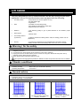
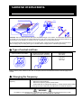
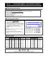
UVItec Ltd Unit 36, St John's Innovation Centre Cowley Road Cambridge CB4 0WS, UK Tel: +44 (0)1223 421270 Fax: +44 (0)1223 421271 E-mail:[email protected] www.uvitec.co.uk 09/2011Index P UV Table USER MANUAL Table of content UV table............................................................. 3 General instructions ................................... 4 BXT-F transilluminator .............................. 5 BTS – 2 wavelengths transilluminator ............................................................................... 6 SXT-F transilluminator .............................. 7 STS - Mixed ..................................................... 8 STS – 35W........................................................ 9 ACCESSORIES ............................................ 10 WARRANTY .................................................. 11 UV table You have purchased a new UV transilluminator. We are sure it will give you entire satisfaction. All our UV transilluminators come equipped with the following: UV safety screen Filter Reflector Filter support UV intensity selector (2 positions) - total protection for the user against UV rays, - fully adjustable angle. - long lifetime - unrivalled UV transmitting quality, - high capacity for absorption of visible light, - brighter fluorescent response. - high reflecting quality to give a perfect diffusion of UV radiation ("Optic" quality). - stainless steel. Security - on BXT-F and SXT-F models (position 100% for reading, position 70% for preparation). - To prevent an excessive use, the transilluminator (only BXT-F; SXT-F models) will switch OFF automatically after a time from 10 to 15 minutes. Warning / On the safety a) This unit must be connected to a wall outlet having protective earth terminal. Connecting to ground is an obligatory protection. b) To prevent fire or shock hazard, do not expose the unit to rain or moisture. c) Unplug the unit from the wall outlet if you do not use it for a long time. Disconnect the power cord by grasping the plug. Never pull the cord itself. d) Never obstruct the air admission grids of the unit. This symbol is warning against a possible UV radiation. Protect the eyes and skin from the UV radiation. Climatic conditions - Altitude - Operating humidity - Operating temperature : 2000 meters : 20% to 80% (no condensation allowed) : 5°C to 33°C General advice - To clean the surface of the filter, use a mild solvent or warm water. Dry with a soft cloth. - The filter is porous, so try to keep it dry. - Normal cycle using: 1 to 25 minutes. SPECTRAL CURVES 312 n m 365 n m RELATIVE IRRADIANCE RELATIVE IRRADIANCE RELATIVE IRRADIANCE 254 n m 270 210 230 250 270 290 290 310 330 350 370 380 n m 310 n m Filter lifetime: 2000 hours Intensity : 7 mW/cm² Unlimited filter life time No 254nm emission guaranteed Intensity : 8 mW/cm² 300 320 340 360 380 400 nm Unlimited filter life time No 254nm emission guaranteed Intensity : 7 mW/cm² General instructions ANTI -SCRATCH UV SAFETY SCREEN HINGE PIN ADJUSTING SCREW SCREW DRIVER TO REM OVE THE UV SAFETY SCREEN, J UST UNSCREW THE TWO HI NGES CAUTION: Switch off the fluorescent table when electrophoresis gel is not present. The fluorescent table should not be kept “On” for more than 25 minutes without gel. If such is the case, switch off the fluorescent table for 20 minutes before a new utilization. If the filter is too hot, it will destroy your electrophoresis gel. All our fluorescent tables are fitted with one or two safety fuses. These are found in the plug at the back of the UV table. The plugs vary according to the type of UV table and the voltage (see the 2 different types below). Type of socket and fuse Type of sockets for all models Sockets for all 100V~ 50/60Hz models except BXT-F and SXT-F Type of fuse (all models) 50Hz 60Hz Type FST Time-lag T Ø 5 x 20 Power: See the power values for each item in the spare parts and characteristics board on the last page of the manual. Changing the frequency BXT/SXT models work at all frequency For other 100V~ - 50/60 Hz models: Remove the fuse holder tray, Remove the frequency selector located inside, Twist a half turn to change the frequency. Check that the value visible through the fuse holder tray corresponds to the desired frequency. WARNING UV radiation can be dangerous for unprotected eyes and skin, therefore we recommend the user to wear UV protective goggles (LP-70) or face-shield (MP-80 or MP-800). BXT F transilluminator Operating instructions Place your UV Table on a level working surface, Plug the unit into a properly grounded electrical outlet, To work in "reading" mode, select position 100%, then switch on the on/off switch To work in "preparation" mode, select position 70%, then switch on the on/off switch After use, switch off the on/off switch. CAUTION: Switch off the fluorescent table when electrophoresis gel is not present on the transilluminator. If the filter is too hot, it will damage your electrophoresis gel. Over 20 minutes, transilluminator will be in energy saving mode. To activate it again, wait for 20 seconds and press switch on. NOTE: Wait at least 20 second in the "100%" position before reducing the intensity selector to "70%". If one or several tubes are off or used, and in order to keep a better homogeneity, UVITEC recommends to change the 6 tubes simultaneously. Changing the tubes a) b) c) d) Before dismantling, unplug the UV Table, Unscrew the 6 fixing screws on the filter support, Remove the filter support, Change the 6 tubes (A quarter turn will release the tubes). IMPORTANT: Reassemble the UV table completely before checking it works correctly. To reassemble the UV table, follow the above instructions in reverse order. Fuses are located in the plug - see page 4. Spare parts Ref. Article BXT-F 15.L BXT-F 15.M BXT-F 15.S BXT-F 20.L BXT-F 20.M BXT-F 20.S BXT-F 20.W BXT-F 26.M BXT-F 26.MX BXT-F 26.S Qty Ref. 4 4 4 6 6 6 2 6 6 6 T-8.L T-8.M T-8.C T-8.L T-8.M T-8.C T-8.WL T-8.M T-8.M T-8.C Tubes Wavelength 365nm 312nm 254nm 365nm 312nm 254nm White light 312nm 312nm 254nm Filter with support W 8W 8W 8W 8W 8W 8W 8W 8W 8W 8W FBT-TC15.CM FBT-TC15.CM FBT-TC15.CM FBT-TC20.CM FBT-TC20.CM FBT-TC20.CM FBT-TC20.W FBT-TC26.CM FBT-TC26.MX FBT-TC26.CM Starter ST-151 (230/115V) FG-7P (100V) 4 4 4 6 6 6 2 6 6 6 Fuse Ø 5 x 20 230 V~ 100 V~ 240 V~ 115 V~ 2A 2A 2A 2A 2A 2A 2A 2A 2A 2A 2A 2A 2A 2A 2A 2A 2A 2A 2A 2A WARNING UV radiation can be dangerous for unprotected eyes and skin, therefore we recommend the user to wear UV protective goggles (LP-70) or face-shield (MP-80 or MP-800). Power 90 W 90 W 90 W 90 W 90 W 90 W 30 W 90 W 90 W 90 W BTS – 2 wavelengths transilluminator Operating instructions - Place your transilluminator on a level working surface, Check that your electrical supply is compatible with the voltage of your transilluminator, Plug the unit into a properly grounded electrical outlet, Select the desired wavelength, Put the O/I switch to the I position The switch diode will light up To change the wavelength, put the switch to position O. After use, select position O. Changing the tubes a) b) c) d) Before dismantling, unplug the TABLE, Unscrew the 6 fixing screws on the filter support, Remove the filter support, Change the 6 tubes of the first wavelength and 5 tubes of the second wavelength, then the 11 starters. (starters are located under the tubes only for the BTS). A quarter turn will release the tubes and the starters. e) CAREFULLY keep tubes in the same order (see diagram) IMPORTANT: Reassemble the transilluminator completely before checking it works correctly. To reassemble the transilluminator, follow the above instructions in reverse order. Fuses are located in the plug (see page 4) X Y X Y X Y X Y X Y X BTS-20.LM/BTS-26.LM : X = T-8.M 312nm : Y = T-8.L 365nm BTS-20.MS/BTS-26.MS : X = T-8.S 254nm : Y = T-8.M 312nm BTS-20.LS/BTS-26.LS : X = T-8.S 254nm : Y = T-8.L 365nm Spare parts Ref. Article Qty BTS-20.LM 5 6 5 6 5 6 5 6 5 6 5 6 BTS-20.MS BTS-20.LS BTS-26.LM BTS-26.MS BTS-26.LS Ref. T-8.L T-8.M T-8.M T-8.S T-8.L T-8.S T-8.L T-8.M T-8.M T-8.S T-8.L T-8.S Tubes Wavelength 365nm 312nm 312nm 254nm 365nm 254nm 365nm 312nm 312nm 254nm 365nm 254nm W 8W 8W 8W 8W 8W 8W 8W 8W 8W 8W 8W 8W Filter with support Starter ST-151 (230/115V) FG-7P (100V) FBT-20.S FBT-20.S FBT-20.S FBT-26.S FBT-26.S FBT-26.S 11 11 11 11 11 11 11 11 11 11 11 11 Fuse Ø 5 x 20 230 V~ 100 V~ 240 V~ 115 V~ 2A 2A 2A 2A 2A 2A 2A 2A 2A 2A 2A 2A 2A 2A 2A 2A 2A 2A 2A 2A 2A 2A 2A 2A Power 96 W 96 W 96 W 96 W 96 W 96 W WARNING UV radiation can be dangerous for unprotected eyes and skin, therefore we recommend the user to wear UV protective goggles (LP-70) or face-shield (MP-80 or MP-800). SXT-F transilluminator Operating instructions Place your UV Table on a level working surface, Plug the unit into a properly grounded electrical outlet, To work in "reading" mode, select position 100%, then switch on the on/off switch To work in "preparation" mode, select position 70%, then switch on the on/off switch After use, switch off the on/off switch. CAUTION: Switch off the fluorescent table when electrophoresis gel is not present on the transilluminator. If the filter is too hot, it will damage your electrophoresis gel. Over 20 minutes, transilluminator will be in energy saving mode. To activate it again, wait for 20 seconds and press switch on. NOTE: Wait at least 20 second in the "100%" position before reducing the intensity selector to "70%". If one or several tubes are off or used, and in order to keep a better homogeneity, UVITEC recommends to change the 6 tubes simultaneously. Changing the tubes a) b) c) d) Before dismantling, unplug the UV Table, Unscrew the 6 fixing screws on the filter support, Remove the filter support, Change the 6 tubes (A quarter turn will release the tubes). IMPORTANT: Reassemble the UV table completely before checking it works correctly. To reassemble the UV table, follow the above instructions in reverse order. Fuses are located in the plug - see page 4. Spare parts Ref. Article SXT-F20.L SXT-F20.M SXT-F20.S SXT-F26.M SXT-F26.S SXT-F26.MX SXT-F36.M SXT-F36.S Qty Ref. Tubes Wavelength W Filter with support Starter ST-151 (230/115V) FG-7P (100V) 6 6 6 6 6 6 6 6 T-15.L T-15.M T-15.S T-15.M T-15.S T-15.M T-15.M T-15.S 365nm 312nm 254nm 312nm 254nm 312nm 312nm 254nm 15W 15W 15W 15W 15W 15W 15W 15W FST-20.S FST-20.S FST-20.S FST-26.S FST-26.S FST-26.MX FST-36.S FST-36.S 6 6 6 6 6 6 6 6 Fuse Ø 5 x 20 230 V~ 100 V~ 240 V~ 115 V~ Power 3.15 A 3.15 A 3.15 A 3.15 A 3.15 A 3.15 A 3.15 A 3.15 A 180 W 180 W 180 W 180 W 180 W 180 W 180 W 180 W 3.15 A 3.15 A 3.15 A 3.15 A 3.15 A 3.15 A 3.15 A 3.15 A WARNING UV radiation can be dangerous for unprotected eyes and skin, therefore we recommend the user to wear UV protective goggles or face-shield. STS - Mixed Operating instructions Place your UV Table on a level working surface, Plug the unit into a properly grounded electrical outlet, To work in "reading" mode, select position 100%, then switch on the on/off switch To work in "preparation" mode, select position 70%, then switch on the on/off switch After use, switch off the on/off switch. CAUTION: Switch off the fluorescent table when electrophoresis gel is not present on the transilluminator. If the filter is too hot, it will damage your electrophoresis gel. Over 20 minutes, transilluminator will be in energy saving mode. To activate it again, wait for 20 seconds and press switch on. NOTE: Wait at least 20 second in the "100%" position before reducing the intensity selector to "70%". If one or several tubes are off or used, and in order to keep a better homogeneity, UVITEC recommends to change the 8 tubes simultaneously. Changing the tubes a) b) c) d) e) Before dismantling, unplug the UV Table, Unscrew the 6 fixing screws on the filter support Remove the filter support Change the 8 tubes and 8 starters (starters are located under the tubes. A quarter turn will release the tubes and the starters). CAUTION : Keep the tubes in the same order IMPORTANT: Reassemble the UV table completely before checking it works correctly. To reassemble the UV table, follow the above instructions in reverse order. Fuses are located in the plug - see page 4. Spare parts Ref. Article STS-20.WS STS-20WM STS-20WL Qty 6 2 6 2 6 2 Ref. T-8.S T-8.WL T-8.M T-8.WL T-8.L T-8.WL Tubes Wavelength 254nm White Light 312nm White Light 365nm White Light W 8W 8W 8W 8W 8W 8W Filter with Support FST-20.WS FST-20.WS FST-20.WS Starter ST-151 (230/115V) FG-7P (100V) 6 2 6 2 6 2 Fuse Ø 5 x 20 230 V~ 100 V~ 240 V~ 115 V~ 2A 2A 2A 2A 2A 2A 2A 2A 2A 2A 2A 2A Power 100 W 100 W 100 W WARNING UV radiation can be dangerous for unprotected eyes and skin, therefore we recommend the user to wear UV protective goggles or face-shield. STS – 35W Operating instructions Place your UV Table on a level working surface, Plug the unit into a properly grounded electrical outlet, To work in "reading" mode, select position 100%, then switch on the on/off switch To work in "preparation" mode, select position 70%, then switch on the on/off switch After use, select position 0. CAUTION: Switch off the fluorescent table if not used. NOTE: Wait at least 20 second in the "100%" position before reducing the intensity selector to "70%" CAUTION: When one or several tubes are out of order, the warning tubes flicker for a short moment at the lighting of the UV table. Then all the tubes are automatically switched off by the security device. For a better homogeneity, UVITEC recommends to change the 2 tubes simultaneously. Changing the tubes a) b) c) d) Before dismantling, unplug the UV table, Unscrew the 6 fixing screws on the filter support, Remove the filter support, Change the 4 tubes and 4 starters (starters are located under the tubes. A quarter turn will release the tubes and the starters). IMPORTANT: Reassemble the UV table completely before checking it functions correctly. To reassemble the UV table, follow the above instructions in reverse order. Fuses are located in the plug - see page 4 Spare parts Ref. Article Qty Ref. STS-35.W 2 2 T-15.WL T-6.WL Tubes Wavelength White Light White Light Filter with support W 15W 6W FS-T35.WL Starter ST-151 (230/115V) FG-1P (100V) 2 2 Fuse Ø 5 x 20 230 V~ 100 V~ 240 V~ 115 V~ 2A 2A 2A 2A Power 80 W WARNING UV radiation can be dangerous for unprotected eyes and skin, therefore we recommend the user to wear UV protective goggles (LP-70) or face-shield (MP-80 or MP-800). ACCESSORIES Conversion filter FC-26.WL : Converter of UV Light in White Light (working area : 260 x 210mm). Protection LP-70 : Goggles for total eye protection. MP-800 : Face-shield for total face and ear protection. Other accessories CV 015W : Viewing cabinet with internal white light that can be fitted onto a standard (large) transilluminator for maximum fluorescence in daylight. A UV-blocking viewing port enables safe viewing of fluorescent objects in the darkroom. The lighting (2 x 40W white light) enables easy positioning of the object to be viewed. CV 415UV : UV viewing cabinet with powerful overhead (epi-) UV lights, that can (large) UV transilluminator for very high UV intensity in daylight. * CV 415.LL 365nm * CV 415.LS * CV 415.SS 254nm * CV 415.LM * CV 415.MM 312nm * CV 415.MS be fitted onto a standard 365/254nm 365/312nm 312/254nm WARRANTY Our products (except Compact Flash®, light tubes and filters) are warranted against faulty construction or defective material for a period of TWO YEARS from the date of supply. Our products are not warranted for damage due to carelessness, incorrect use or bad maintenance. The following defects are also specifically excluded: - Defects caused by improper operation. - Repair or modification done by anyone other than UVITEC or an authorised agent. - Corrosion caused by improper solvents or samples. - Use of spare parts supplied by anyone other than UVITEC. - Damage caused by accident or misuse. - Damage caused by disaster. This instrument should not be modified or altered in any way. Modification or alteration of this instrument will: 1. Void the manufacturer’s warranty. 2. Void the conformity certifications. 3. Create a potential safety hazard. ® The Compact Flash , the tubes and the filters are not covered by our warranty. The use of consumable products or non-original spare parts not recommended by our service department is at the user's own risk and therefore automatically invalidates the warranty. Tubes, filters, batteries and consumable products are not included in the warranty. We reserve the right to decide where the faulty goods will be repaired (in our workshop or elsewhere), and whether or not the faulty part is to be replaced; all other freight charges incurred being at the cost of the purchaser. Returned goods will not be accepted for repair unless previous written authorisation is obtained from our service department. A request for authorisation must be accompanied by an itemised list of products, model numbers and the corresponding invoice numbers under which they were originally shipped. All returned goods should have a certificate of decontamination. The Buyer must bear all costs and risks incurred during the transportation of the goods from their collection at UVITEC warehouse. In the case UVITEC incorporates some devices or equipment from another supplier in the manufacture of its products, the extent and the duration of the warranty will be those conceded by the suppliers or sellers. Manufacturer cannot be held responsible for any loss, bodily injury or material accident incurred by any failure of this supply, whatever the origin of this failure may be. The responsibility of Manufacturer is strictly limited to its staff and to its own supplies. In the case of dispute, only the commercial court of Cambridge (United Kingdom) shall be competent, even in third party claims proceedings or when there are several co-defendants. NOTE: UVITEC is not responsible for any injury or damage caused by use of this instrument for purposes other than those for which it is intended, or by modifications of the instrument not performed by UVITEC. Decontamination, collection and elimination of waste The buyer ensures and finances the decontamination, the collection and the disposal of waste electrical and electronic equipment (WEEE) under the conditions provided in the Articles 21 and 22 of the Decree No. 2005-829 dated of 20 July 2005. Improper disposal may be harmful to the environment and human health. Declaration of conformity The materials complies with the requirements of the EC Directive 2004/108/EEC, 2006/95/EEC and EN 61010-1 (electro-magnetic compatibility and low voltage). The electro-magnetic susceptibility has been chosen at a level that gains proper operation in residential areas, on business and light industrial premises and on small-scale enterprises, inside as well as outside of the buildings. All places of operation are characterized by their connection to the public low voltage power supply system.