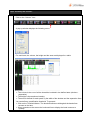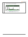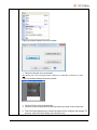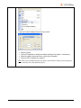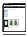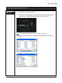
1
USER & SERVICE MANUAL 09/2010-index c 1/128 Thank you Dear Customer, On behalf of UVItec, we would like to thank you for choosing the UVISAVE imaging systems. In order to learn the capabilities of your UVISAVE system, we kindly ask you to read this manual. This manual details how to install and to operate the hardware and the software components. UVItec is dedicated to your satisfaction and we will be pleased to answer any question you may have. We are also very receptive to your suggestions. Many of the new features and enhancements in this system are a direct result of conversations with our customers. Please do not hesitate to contact us to let us know what you would like to see in the next version of this system. You can contact us at the following addresses: Email: [email protected] Contact address: UVItec Limited Avebury House, 36a Union Lane Cambridge CB4 1QB United Kingdom Tel: +44 (0)1223 568 060 Fax: +44 (0)1223 306 198 Do not hesitate to visit our website at www.uvitec.co.uk 2/128 Table of content WARNING AND SAFETY ............................................................................................................................................ 6 END USER LICENSE AGREEMENT ............................................................................................................................ 10 INTRODUCTION ..................................................................................................................................................... 12 Key features.......................................................................................................................................................... 12 HARDWARE INSTALLATION .................................................................................................................................... 13 Unpacking the UVISAVE HD2 system ............................................................................................................... 13 Installing the hardware...................................................................................................................................... 15 UVISAVE 1D SOFTWARE INSTALLATION.................................................................................................................. 18 Software installation – Preliminary steps ....................................................................................................... 18 Minimum computer requirements for the UVIsave 1D software............................................................ 19 Software installation ........................................................................................................................................... 20 Upgrading the software .................................................................................................................................... 22 UVIsave 1D un-install .......................................................................................................................................... 22 SYSTEM OPERATION .............................................................................................................................................. 23 Warning and security issues ............................................................................................................................. 23 Main switch........................................................................................................................................................... 24 UVIsave HD2 operating environment............................................................................................................ 25 IMAGE CAPTURE .................................................................................................................................................... 26 Live preview ......................................................................................................................................................... 26 Exposure time ....................................................................................................................................................... 27 Freeze ..................................................................................................................................................................... 30 Auto ........................................................................................................................................................................ 31 Save ........................................................................................................................................................................ 32 Print ......................................................................................................................................................................... 33 Zoom + ................................................................................................................................................................... 34 Next / Back ........................................................................................................................................................... 35 Focus point adjustment..................................................................................................................................... 36 SET-UP MENU ........................................................................................................................................................ 37 Set-up menu operating environment ........................................................................................................... 37 Display the saturation ........................................................................................................................................ 39 Add a grid............................................................................................................................................................. 40 3/128 Stamp date and time ........................................................................................................................................ 40 Open an image .................................................................................................................................................. 41 Delete an image................................................................................................................................................. 42 Set date and time .............................................................................................................................................. 43 Unlock (i.e. Add a printer) ................................................................................................................................ 44 About ..................................................................................................................................................................... 49 Firmware update ................................................................................................................................................ 50 USB device precaution ..................................................................................................................................... 50 QUICK START ......................................................................................................................................................... 51 Taking your first picture ...................................................................................................................................... 51 USING THE UVISAVE 1D SOFTWARE ....................................................................................................................... 52 UVIsave 1D operating environment .............................................................................................................. 52 Navigating the menu bar ................................................................................................................................. 54 Navigating the function folder ....................................................................................................................... 56 Navigating the toolbar...................................................................................................................................... 57 The status bar ....................................................................................................................................................... 57 THE STATUS BAR................................................................................................................................................................ 58 Introduction .......................................................................................................................................................... 58 The image master ............................................................................................................................................... 58 Display - Autoscale ............................................................................................................................................. 59 Display - Inverse ................................................................................................................................................... 59 Display - Saturation............................................................................................................................................. 60 Display – Minimum / Maximum / Default ..................................................................................................... 60 Display - Gamma ................................................................................................................................................ 61 Enhance - Date ................................................................................................................................................... 62 Enhance – Brightness / Contrast ..................................................................................................................... 63 Enhance – Rotate / Mirroring .......................................................................................................................... 65 Enhance – Pseudo colours ............................................................................................................................... 66 Enhance - Text ..................................................................................................................................................... 68 Enhance – Reset enhancement..................................................................................................................... 68 IMAGE ANALYSIS – MOLECULAR WEIGHT ................................................................................................................................ 69 Accessing the quick image analysis menu ................................................................................................. 69 Step 1: Define the number of lanes ............................................................................................................... 70 Step 2: Detect the bands ................................................................................................................................ 72 Step 3: Load or define the marker values ................................................................................................... 74 Step 4: Get the results ........................................................................................................................................ 77 Step 5: Quantify the volumes .......................................................................................................................... 78 Printing the results ............................................................................................................................................... 80 Autofit ..................................................................................................................................................................... 83 Default display ..................................................................................................................................................... 83 Returning to the main menu............................................................................................................................ 84 IMAGE ANALYSIS – COLONY COUNTING .................................................................................................................................. 85 Open an image and select the colony counting menu ......................................................................... 85 Automatic colony counting ............................................................................................................................ 86 Manual colony counting .................................................................................................................................. 89 Printing the results ............................................................................................................................................... 90 Autofit ..................................................................................................................................................................... 92 Default display ..................................................................................................................................................... 93 Returning to the image main menu .............................................................................................................. 94 IMAGE ANALYSIS – RF ........................................................................................................................................................ 95 Open an image and select the distance calculation (RF) menu ........................................................ 95 Step 1: Define the number of lanes ............................................................................................................... 96 Step 2: Detect the bands ................................................................................................................................. 97 Step 3: Assign the RF values ............................................................................................................................. 99 4/128 Step 4: Get the results ..................................................................................................................................... 100 Step 5: Quantify the volumes ........................................................................................................................ 101 Printing the results ............................................................................................................................................. 104 Autofit ................................................................................................................................................................... 106 Default display ................................................................................................................................................... 107 Returning to the image main menu ............................................................................................................ 108 IMAGE ANALYSIS – UVISOFT SOFTWARE............................................................................................................................... 109 Sending the image to the UVIband analysis software ........................................................................... 109 CONTROLS AND PARAMETERS ............................................................................................................................................ 110 Accessing the controls & parameters folder ............................................................................................ 110 UVIsave 1D parameters .................................................................................................................................. 110 Good laboratory practice (GLP).................................................................................................................. 113 Crop images ...................................................................................................................................................... 113 Merge images ................................................................................................................................................... 115 TOOLBAR IN DETAILS ........................................................................................................................................................ 116 Opening an image .......................................................................................................................................... 116 Saving an image ............................................................................................................................................... 117 Printing ................................................................................................................................................................. 118 Printing on the video printer (if applicable – Optional) ......................................................................... 119 Crop – Defining the area to be saved ....................................................................................................... 120 Saving the user settings ................................................................................................................................... 121 Loading the user settings ................................................................................................................................ 122 Using the contextual help .............................................................................................................................. 122 MAINTENANCE .................................................................................................................................................... 123 Camera room .................................................................................................................................................... 123 Working part ....................................................................................................................................................... 123 Air admission grid .............................................................................................................................................. 123 TECHNICAL INFORMATION................................................................................................................................... 124 Electrical specifications................................................................................................................................... 124 Climatic conditions .......................................................................................................................................... 124 SPARE PARTS ....................................................................................................................................................... 125 Spare parts.......................................................................................................................................................... 125 WARRANTY ......................................................................................................................................................... 126 CONFORMITY ...................................................................................................................................................... 128 5/128 WARNING AND SAFETY Please read carefully these instructions before installing and operating the UVISAVE HD2 system. Whenever you find this pictograph, be sure to refer to this Manual. It indicates an imminently hazardous situation which, if not avoided, could result in death or serious injury. Whenever you find this pictograph, be sure to refer to this Manual. It indicates a UV radiation situation which, if not avoided, could result in serious injury. WARNING The operator should wear appropriate safety glasses or a protective mask and gloves. UV radiation can be dangerous for unprotected eyes and skin; therefore we recommend the user to wear UV protective goggles (LP-70) or face-shield (MP-80 or MP-800). 6/128 This product is safe to use when operated in accordance with the instruction manual. This instrument should not be modified or altered in any way. Modification or alteration of this instrument will void the manufacturer’s warranty, void the regulatory certifications and create a potential safety hazard. The intended purpose of the UVISAVE HD2 is gel documentation. The system is designed for research use in laboratory only. UVITEC is not responsible for any injury or damage caused by the use of this instrument for purposes other than those for which it is intended, or for any modifications of the instrument not performed by UVITEC or by an authorized agent. All uses opposed to the notification specified in this technical instruction or all misuses affect the goods and bodies security fastened by this device and can damage the instrument. It is mandatory to connect the UVISAVE HD2 to an appropriate AC voltage outlet that is properly grounded and protected by a circuit breaker. Connecting to ground constitutes an obligatory protection. It is mandatory to power down the system and to disconnect the AC main from the unit before performing any disassembly or repair the instrument. The system must be unplugged from the AC voltage outlet if it is not intended to use it before a long time. Disconnect the power cord by pulling the plug. Never pull on the cord itself. Ensure that all the ventilation-opening systems are not obstructed. The obstruction of the air admission grids may affect the performance of the system and cause operational failure. To prevent fire or shock hazard, do no expose the unit to rain or moisture. The use of accessories not supplied by UVITEC can damage the system or create safety hazard. Do not use the UVISAVE HD2 in dangerous atmosphere or with dangerous materials for which the UVISAVE HD2 has not been designed for. The power cable of the camera is expensive and very fragile, because of the thin conducting pin. Before plugging or unplugging the cable, ensure the unit is off and disconnect the UVISAVE HD2 from the AC voltage outlet. Never pull the camera cable itself. Disconnect the cable only by grasping the plug. 7/128 All the equipment connected to this unit shall be certified according to standard IEC 950, or other IEC/ISO Standards applicable to the equipment. Do not pour liquids directly on or inside the instrument. Switch off all the lights immediately after use. Clean the transilluminator platen after use. The system should be located away from water, solvents, or a corrosive material, on a bench top that is dry and stable. The system should be placed away from interfering electrical signals and magnetic fields. A dedicated electrical outlet should be used to eliminate electrical interference from other instrumentation in your laboratory. 8/128 TRADEMARKS Windows, Windows XP, Windows Vista, Windows 7, Excel, Microsoft, and Power Point are trademarks of Microsoft Corporation. Intel Pentium, Intel Core are trademarks of Intel Corporation. FireWire, Mac, and Mac OS X are trademarks of Apple Inc. Coomassie is a trademark of BASF Aktiengesellschaft. Cy is a trademark of GE Healthcare group companies. SYBR Safe, SYBR Green, SYBR Gold, and SYPRO are trademarks of Invitrogen Corporation. Other brands or product names are trademarks of their respective holders. This instrument must be used only by specialized personnel that know the health risks associated with UV radiation and with the reagents that are normally used with this instrument. Use of the UV protective screen doesn’t guarantee protection of the user from UV radiation. The use of protective eyeglasses or mask and gloves is highly recommended. 9/128 END USER LICENSE AGREEMENT Please read these instructions before installing and operating the UVIsave system and software Please read carefully the following license agreement. This document is a legal agreement between you, and UVItec, concerning the use of the enclosed software. This agreement constitutes the complete agreement between you and UVItec. By opening the software package or using the CD, you are consenting to be bound by and are becoming a party to this agreement. If you do not agree To all of the terms of this agreement, do not open the package or use the CD. Promptly return the CD, including the written materials, the binder, and all other equipment/containers to the dealer from whom you purchased them. License Grant The package contains software ("Software") and related explanatory written materials ("Documentation"). "Software" includes any upgrades, modified versions, updates, additions and copies of the Software. "You" means the person or company who is being licensed to use the Software or Documentation. "We" and "us" means UVItec, SAS. We hereby grant you a nonexclusive, limited license to use one copy of the Software on any single computer, provided the Software is in use on only one computer at any time. The Software is "in use" on a computer when it is loaded into temporary memory (RAM) or installed into the permanent memory of a computer—for example, a hard disk, CD-ROM or other storage device. If the Software is permanently installed on the hard disk or other storage device of a desktop or portable computer (other than a network server) and one person uses that computer more than 80% of the time, then that person may also use the Software on a 2nd computer for the purpose of viewing and post-processing images. Title We remain the owner of all right, title and interest in the Software and Documentation. You will agree to use your best efforts to protect the software from unauthorized use, illegal reproduction, or illicit distribution. 10/128 Copyrights and Trade Secrets UVItec owns all rights to the Software. This agreement does not convey ownership of the software to you, but only the right to use a copy of the software strictly in accordance with this agreement. The unauthorized duplication or distribution of the software or the documentation is an infringement of UVItec’ rights to the software and may be subject to criminal and/or civil penalties. Archival or Backup Copies You may either: • Make one copy of the Software solely for backup or archival purposes, provided that the original copyright notice and/or other legend is reproduced on each copy, or • Transfer the Software to a single hard disk, provided you keep the original solely for backup or archival purposes, and provided that the original copyright notice and/or other legend is reproduced on each copy. Terms and Termination This license agreement takes effect upon your use of the software and remains effective until terminated. You may terminate it at any time by destroying all copies of the Software and Documentation in your possession. It will also automatically terminate if you fail to comply with any term or condition of this license agreement. You agree on termination of this license to either return to us or destroy all copies of the Software and Documentation in your possession. Confidentiality The Software contains trade secrets and proprietary know-how that belong to us and it is being made available to you in strict confidence. Any use or disclosure of the software, or of its algorithms, protocols or interfaces, other than in strict accordance with this license agreement, may be actionable as a violation of our trade secret rights. General Provisions • This written license agreement is the exclusive agreement between you and us concerning the Software and Documentation and supersedes any and all prior oral or written agreements, negotiations or other dealings between us concerning the Software. • This license agreement may be modified only by a written agreement signed by you and us that specifically supersedes this agreement. • This license agreement is governed by the British laws Copyright 2006-2010, UVItec Ltd All rights reserved. Windows Vista, Windows XP, Windows Excel, Windows Office are trademark of Microsoft, Inc. All other product names mentioned in this document are the property of their respective trademark holders. 11/128 INTRODUCTION Easy and fun UVIsave HD2 is a stand-alone imaging system dedicated to basic gel documentation. Thanks to its built-in USB media drive, the images can be saved on a USB stick or printed on a thermal printer for instant hard-copy images. UVIsave HD2 combines simplicity and economy for laboratories with budget in mind. Key features No computer required for image acquisition or printing Publication and quantification of high quality images What you see is what you get 12-bit imaging Highly sensitive CCD camera USB key saving media Pixel saturation warning All the necessary information to ensure the optimum quality of your image Compact and robust darkroom TIFF image format Good laboratory practice file (GLP) Complimentary UVIsave 1D software 12/128 HARDWARE INSTALLATION Unpacking the UVISAVE HD2 system Do not handle the system by the camera or the camera support. Please, open the UVISAVE HD2 box carefully and verify the contents: UVISAVE HD2 Darkroom / Camera and camera support Power cable Instruction manual UVIsave 1D software CD-Rom inside the instruction manual 1 1 1 1 Remove carefully each component from the box. To remove the UVISAVE HD2 from the box, please use the belts which surround the system and designed for this purpose Do not handle the system by the camera or the camera support. Remove their protective plastic cover. Do not connect the power cable to a power source until all connections are made. The power source has to be grounded and protected by a circuit breaker. The UVISAVE HD2 system is designed to fit a specific voltage. Please, check the voltage to ensure it corresponds to the UVISAVE HD2 specifications. 13/128 Please keep an open area of at least 20 cm around of the UVIsave HD2 to ensure a proper air circulation for the system. The system should be located in an area free of excessive dust or moisture, strong magnetic fields or ionising radiation. It is also recommended that the ambient temperature be stable and within the range of 15°C to 25°C (20°C recommended) and that the relative humidity not exceed 70%, non-condensing. Ensure that all of the systems ventilation openings are free of interference. Excessive heat buildup in the instrument may affect performance or cause operational failure. Do not defeat any instrument interlocks; they are designed to prevent user injury It is compulsory to power down the system and disconnect the AC mains from the unit before performing any disassembly or repair to the system. WARNING The use of the UVISAVE HD2 together with a transilluminator darkroom, involves ultraviolet (UV) illumination. Proper precautions must be taken to avoid eye and skin exposure to the UV light. This instrument is meant for use only by specialized personnel that know the health risks associated with UV radiation and the chemicals that are normally used with this instrument. WARNING The operator should wear appropriate safety glasses or a protective mask and gloves. UV radiation can be dangerous for unprotected eyes and skin; therefore we recommend the user to wear UV protective goggles (LP-70) or face-shield (MP-80 or MP-800). WARNING The UVISAVE HD2 system should be located away from water, solvents, or a corrosive material, on a bench top that is dry and stable. The system should be placed away from interfering electrical signals and magnetic fields. A dedicated electrical outlet should be used to eliminate electrical interference from other instrumentation in your laboratory. 14/128 Note: The UVISAVE 1D software runs only with Windows® XP SP2 (or upper) (32-bit) or Windows Vista SP1 (or upper) (32-bit) operating system. You must ensure Windows® is installed on your computer before performing the UVIsave 1D installation. Installing the hardware Place the UVISAVE HD2 on a level-working surface. Stand-by Port 4 Figure 1 Port 4: The USB port is particularly designed to hold your USB key drive for image saving. 15/128 Camera UVISAVE rear side drawing: Port 2 Port 3 Main switch Port 1 Fuses Figure 3 16/128 Port 1: Power supply and main switch Port 2: Camera cable USB port Port 3: Printer cable USB port Port 4: Available USB port (figure 1) Connect the ―USB Camera cable‖ from the camera to the rear side USB port n°2 of the UVISAVE HD2 box, as shown in figure 3. Connect the ―Power supply cable‖ from the rear side of the system to an earth electrical outlet, as shown in figure 3. It is mandatory to connect the system to an appropriate AC voltage outlet that is properly grounded and protected by a circuit breaker. Connecting to ground constitutes an obligatory protection. 17/128 UVISAVE 1D SOFTWARE INSTALLATION Software installation – Preliminary steps UVISAVE 1D runs with Microsoft WindowsTM XP SP2 (& upper) or Microsoft VistaTM (or upper) (32-bit only) operating systems. WindowsTM or VistaTM must be installed on your computer before any other installation. Windows® is a registered trademark of Microsoft Note: During the driver installation, the Windows installation CD-ROM might be required. Please, check you have it before starting the UVIsave 1D software installation 18/128 Minimum computer requirements for the UVIsave 1D software Minimum requirement Bus PCI bus (Intel chipset) supporting bus mastering mode Processor Intel Core 2 Duo and upwards Ram 1 Gb and upwards Hard disk 10 Gb and upwards At least 1Gb free disk space least in order to allow software installation and image storage Monitor / Video card AGP card 1280 x 1024 in 16 millions colour mode (24-bit). Upper resolutions supported Video card with a refresh rate above 70 Hz. Operating system Microsoft Windows XP SP2 (and upper) (32-bit only) Microsoft Windows Vista SP1 (and upper) (32-bit only) USB Port At least two USB port available UVITEC cannot guaranty the correct working of the computer and the software when the BIOS energy saving options are active Windows® is a registered trademark of Microsoft and must be installed before installing the acquisition board and the UVIsave 1D software Do not plug or unplug a USB key drive while the camera is on using the live mode or the exposure mode 19/128 Software installation Step 1 Ensure all application programs are closed. Windows XP and Windows Vista users should also ensure that they are logged on with administrator privileges. Insert the CD-ROM in the CD-ROM drive If the Autorun option is set on your computer, the UVIsave 1D installation will start automatically. If not, double click on the Autorun.exe file to start the installation of the software. The UVIsave 1D Setup window will appear, welcoming you to the Install Wizard for UVIsave 1D Setup. Please click on the Install software icon. Step 2 A pop-up windows displays the following welcome screen: Click on the ―Next‖ button to continue. Select the destination directory. The default destination directory is displayed C:\Program Files\UVIsave 1D 20/128 You can select another directory by clicking on the ―Browse‖ button and select the directory on which you went to set the UVIsave 1D software. Click on the ―Next‖ button to continue. The program files are installed in the specified directory. Once the software is installed, the system is updated. This can take on few minutes, depending on the computer speed. As soon as this process is over, please, reboot the computer when the installation software proposes it. UVIsoft group consists of the icon of the software and of the un-install program. Click twice on the program icon to run it. The most current way to launch the software is to click on the Windows® ―Start‖ button then on ―All programs‖ and then on ―UVIsoft‖ group. To open the UVIsave 1D software, click on UVIsave 1D from the UVIsoft group. 21/128 Upgrading the software If you want to upgrade the software to this version, proceed as described in the first Installation chapter. UVIsave 1D un-install You may want to un-install the software from your hard disk. The uninstUVISAVE 1D program will do it for you. Click on ―Start‖ button Go to ―Programs‖, select UVIsoft and click on uninstUVIsave 1D Answer ―Yes‖ to the question and programs are removed Click on ―OK‖ to finish de-installation 22/128 SYSTEM OPERATION Warning and security issues WARNING The transilluminator is used for the fluorescence applications. WARNING The use of the UVISAVE HD2 involves ultraviolet (UV) illumination. Proper precautions must be taken to avoid eye and skin exposure to the UV light. This instrument is meant for use only by specialised personnel that know the health risks associated with UV radiation and the chemicals that are normally used with this instrument. WARNING The operator should wear appropriate safety glasses or a protective mask and gloves. UV radiation can be dangerous for unprotected eyes and skin; therefore we recommend the user to wear UV protective goggles (LP-70) or face-shield (MP-80 or MP-800). Caution: Switch off the transilluminator when gel is not present on the UV filter. If the filter is too hot, it will damage your electrophoresis gel. 23/128 Main switch The UVISAVE HD2 main switch is located at rear side: USB camera and printer connections Port 1: Main switch and Power supply connection Switch on the main switch before to use the system. 24/128 UVIsave HD2 operating environment Power the UVISAVE HD2 using the ON/OFF switch of the control panel. ON/OFF After boot-up, the UVISAVE firmware will automatically start, and the following screen will appear: 25/128 IMAGE CAPTURE Live preview 1. Live mode allows direct visualization of the image. This mode enables you to adjust the zoom, the focus and the aperture and to position your sample. Note: A live image means the image displayed is refreshed every 1/30th of a second. This short exposure time (or frame) is adequate for a variety of white light samples including protein gels and autoradiography. However, a live image is not sufficient for most samples, which are visualized and photographed over a relatively dim UV light source. A feature called exposure compensates the low light situation by allowing the CCD camera to obtain a timed exposure. Note: After 2 minutes, the firmware will automatically stop the live preview. Click on Live a second time or on Freeze to captures the last image. 26/128 Exposure time The emission light signal coming from the gel could be relatively dim. A feature called exposure time compensates this low light situation. This allows the CCD camera to collect the incoming light over a greater period of time. The exposure time is the acquisition of an image by summing the signal of the camera during the time displayed under integration time button. When the specified exposure time is reached, the image is displayed on the video monitor. The CCD continues to integrate the image and the displayed image is refreshed each time the set exposure time is reached. You can modify the exposure time using the following keys: to increase the exposure time to decrease the exposure time Note: Exposure time is the integration of the image on the CCD sensor over a period of time. The effect is similar to exposure time for a standard camera. Note: The maximum exposure time is 5 seconds. Note: The Live mode corresponds to an exposure time of 1/30 second. Note: The selected exposure time is displayed on the monitor while acquiring the image. Note: When the specified exposure time is reached, the last captured image is displayed. The camera continues to integrate the image on the CCD sensor, updating the display whenever the specified exposure time is reached. The Freeze button stops the exposure process. The last full exposure is displayed. Click on Freeze to stop the exposure time and to capture the last image. The exposure time is displayed in the control bar of the monitor, as shown in the illustration below: 27/128 Image dynamic: The image dynamic is crucial for quantitative accuracy. It should to be the largest possible within the gray scale of the system. 4096 gray levels for 12-bit imaging The gray scale is the total number of levels between white and black. The image dynamic range within this scale. Adjustments are necessary to obtain an image with the broadest dynamic. With most of the gels, a real time image has a limited dynamic. In this case, the exposure time enhances the image dynamic. In order to obtain an optimum image, you can control the image dynamic by adjusting the exposure time. The image dynamic is displayed in the ―Amplitude‖ bar graph as shown in the illustration below: Illustration of the use of the Dynamic bar graph: 28/128 Increasing the exposure time enhances the image dynamic 29/128 Freeze The freeze key stops the exposure process and captures the last image for further saving or printing. To proceed, click on the Freeze key ( ) to stop the image acquisition. The monitor displays the last full exposure. Note: By pressing the Live key or the exposure time keys, the image is released from the freeze status. The following screen will appear after the image is frozen: 30/128 Auto The UVISAVE HD2 system can calculate the necessary exposure time (Auto-exposure) for a standard gel. When you select the Auto-Exposure option, the system samples the light levels and uses the values to calculate the final exposure time. Note: With long integration time, a delay could be necessary before an image is displayed on the monitor. The acquisition will stop automatically at the end of the exposure time. At the end of the auto-exposure process, the image is automatically frozen. The following screen will appear: 31/128 Save Clicking on Save will start the saving of the captured image. The image is saved on the USB® key drive, according to the default image format. To proceed, click on the ―Save‖ ( ) key. Note: The image file is named by the system. The default image name has 8 characters. The first 2 are IM. The last 6 are a number ascending from 000001 to 999999. Note: The default file name is incremented by one each time an image is saved. Note: The file extension varies according to the image file format: For TIFF, the extension is TIF 32/128 Print To print, press the ―Print‖ key ( ). The image is printed on the default printer, if defined. Note: a printer message can appear on the display in the case of lack of ink or paper. In such case the message should disappear after few seconds. If not, please press any touch from the panel and the message will disappear after few seconds. 33/128 Zoom + You can zoom in the image when pressing the Zoom + key. Then, with the up/down/left/right arrows, you can navigate with the image: The zoom view displays the ―Amplitude‖ bar graph as well as the minimum and maximum grey level for the image: Press the Back key to return to the previous menu. 34/128 Next / Back The Next and Back keys help you to navigate within the menu: From the Next button, you access the Print, Save and Zoom keys. From the back button, you access the Live, Exposure and Auto keys. 35/128 Focus point adjustment All cameras require a focus point adjustment. In order to proceed, you have to zoom to the maximum on a straight forward image (a printed paper, a business card ...). Then, focus till you obtain a very sharp image on the screen. This procedure can be done with epi-illumination light and a printed paper. The focus point adjustment varies with the focal distance. You may need to adjust the 3 settings of the zoom lens: - Aperture. Aperture allows the CCD sensor to receive more or less light. Closing the aperture decreases the amount of light coming to the sensor, thereby making the image darker. - Zoom. Zoom allows you to change the size of your sample, on the image. To proceed, click on the In or Out. The zoom automatically moves to the new value. The zoom control will not affect the focus. - Focus. Focus is needed to adjust the sharpness of the image. Turning the ring clockwise or counter clockwise changes the focal point of the lens. In order to properly adjust the focus, please proceed as follows : 1/ Adjust the diaphragm ring on aperture 4 2/ Adjust the zoom ring on position ―69‖ 3/ Put a sharp written paper on the transilluminator (transilluminator has to be off) 4/ Open slightly the darkroom door to obtain a bright image on the display 5/ Adjust the focus ring in order to obtain a sharp image. At this stage, the image must be sharp whatever the zoom ring position is. Do not change the focus ring position anymore as far as you do not modify the focal distance. The lower the f-stop number, the brighter the image will be. For enhanced gel imaging, we suggest to position the diaphragm ring around aperture ―4‖. 36/128 SET-UP MENU Set-up menu operating environment You can access a set-up menu from which you will be able to manage the following functions: Display the saturation Add a grid Stamp the date & time Open or delete an image Modify the date and time Unlock the system and add a device such as a printer Check the system status and version To access the Set-up menu, press the Set-up menu key ( ). All the functions of the set-up menu are described in details in the Setup Menu chapter of this manual. 37/128 38/128 Display the saturation Saturation occurs if the amount of light collected by the camera exceeds its capacity. In such case, the image is over-exposed and the integration time should be reduced. A saturated image is inappropriate for image quantification with image analysis software. The saturation option allows you to visualize the saturated pixels in order to avoid flattening the peaks. To proceed, press the saturation key. The saturated pixels appear in red on the display. Note: A saturated image creates quantification error when studied by image analysis software. Note: To un-activate the saturation option press the saturation key one more time. Note: The image saturation is also indicated by a red line in the Amplitude graph. 39/128 Add a grid With the grid option, you can display a grid on the screen to adjust your gel according to horizontal and vertical axis. To proceed, press the Add a grid key. The grid appears as below with the Live mode: Note: The grid option is only available with the Live mode and Exposure mode. Note: You can remove the grid option by deselecting this option. Stamp date and time You can activate or un-activate the display of the status bar and of the date and time bar. To proceed, press the Insert date and time key ( ). Note: The image is printed according to the Display option. If the date and time bar is displayed, the image will be printed with the date and the time stamped on the print. 40/128 Open an image You can open an image from the internal memory or from your USB key drive for further printing. To process, press Open an image ( ). A pop-up window displays the list of drive and the list of images for the selected drive: Select the drive by using the up and down keys: or Then, select the Files option using the left and right keys: or Select a specific file by using the up and down keys: or Validate using the OK key: Note: By pressing the Cancel key, you could return to the image acquisition mode. Note: An image thumbnail is displayed when a file is selected. Note: Only the images of the default image format are displayed. 41/128 Delete an image You can delete an image from your USB key drive for further printing. To process, press Delete an image ( ). A popup window displays the list of drive and the list of images for the selected drive: Select the drive by using the up and down keys: or Then, select the Files option using the left and right keys: or Select a specific file by using the up and down keys: or Validate using the OK key: Note: By pressing the Cancel key, you could return to the image acquisition mode. Note: An image thumbnail is displayed when a file is selected. Note: Only the images of the default image format are displayed. 42/128 Set date and time The UVISAVE HD2 has a clock that records the date and time at which you take each picture. The information is recorded in the image property of the Good Laboratory Practice (GLP) file. To change the date, hour and time zone, you need to unlock the system. Please refer to the Unlock chapter of this manual. When unlock, you can set the date and time from the Option folder of the Set-up menu. The following display will appear: Select the date, the time zone and the time by using the left and right keys: or Then, select the appropriate option using the up and down keys: or Validate using the OK key: 43/128 Unlock (i.e. Add a printer) The UVISAVE HD2 system is write-protected to prevents the installation of any none approved programs or files such as malware or virus. Thanks to the write-protected function, all files that are not writeprotected are removed with a restart of the system. In other words, a simple reboot will remove any malware or virus that would have been able to infect the UVISAVE system. The Add a device function is designed to unlock the system to allow the installation of additional drivers (such as printer drivers). With the Add a device function, the write-protection is disabled after the system is restarted. At that time, you can install the needed drivers. Upon reboot, the system will have the new drivers installed, and will be write-protected again. Before to add a device, it is compulsory to scan for virus the USB key drive which will contain the driver to be installed in the UVISAVE system. Validate using the OK key: or select Cancel. By validating, the system will reboot to allow device installation or removal. Upon reboot, select the Add a device option. When the system is unlocked, the following display will appear: 44/128 Disconnect the camera from its USB port Connect a mouse and a keyboard to the UVIsave The Add a device display the following window: ―Scan for installed printers‖ will retrieve the list of installed printer drivers. The ―Current printer‖ option lists the installed printers. The ―Define as default printer‖ set the selected printer as the default printer. This means images will be printed with this default printer. 45/128 How to add a printer (new printer driver installation) To add a printer, you need to connect a USB keyboard and a USB mouse. The ―Add a device‖ will then display the following window: Install the USB Printer Driver on a USB key drive. Plug in the USB printer, switch on the printer and wait for the Windows Add a Printer Wizard. The following window will be displayed: Select ―Install from a list or specific location (Advanced) Then, click on Next. The following window will be displayed: 46/128 Select the USB key drive which contain the printer driver. Then, click on Next. The following window will be displayed: Then, the following window will be displayed: 47/128 Click on finish. The printer is then installed. Please switch off the UVISAVE HD2 system and re-start. 48/128 About The About folder summarizes the information concerning your UVISAVE and its set-up. It gives you access to the following information: Systems name & version Camera state Printer state To access About menu, press the Set-up menu key and select the About option: If a USB key drive is connected, you can export the UVISAVE information to the USB key by creating a text file when pressing the Export key: 49/128 Firmware update If suggested by UVItec, the UVISAVE firmware can be updated using a special program and a zip file provided by UVItec. This program and this zip file need to be copied on a USB key drive. Insert the drive in the UVISAVE and access the About function through the Set-Up. The About folder summarizes the information concerning your UVISAVE and its set-up. It gives you access to the following information: Systems name & version Camera state Printer state To access About menu, press the Set-up menu key and select the About option: The following menu will appear: Select the update key. The system will reboot automatically. This procedure last few minutes. Please do not try to access the system during the updating time. USB device precaution DO NOT PLUG OR UNPLUG A USB KEY DRIVE WHILE THE CAMERA IS ON USING THE LIVE MODE OR THE EXPOSURE MODE 50/128 QUICK START Taking your first picture Switch on the UVISAVE Click on aperture and the focus to position your sample and to adjust the zoom, the Switch off the white light and switch on the UV light Click on or Freeze your image with the keys to adjust the exposure time key Switch off the UV light Save your image with the key Print your image with the key 51/128 USING THE UVISAVE 1D SOFTWARE UVIsave 1D operating environment The UVISAVE HD2 is supported by the UVIsave 1D software. Power on the computer. After the computer has booted up completely, double click on the UVISAVE 1D icon : The UVIsave 1D software opens to the following image window: Open an image and a folder menu appears on the left hand side of the display: 52/128 Open an image and a folder menu appears on the left hand side of the display: The UVIsave 1D operating environment is organised into five areas: 1. The menu bar 2. The toolbar 3. The functions folder 4. The status bar 5. The image window 1 2 4 5 3 53/128 Navigating the menu bar Main menu bar The main menu bar is organised into six areas: 1. File 2. Edit 3. Image analysis 4. Text and enhancement 5. Controls and parameters 6. Window 7. Help The following image illustrates the main menu bar: File menu The File menu contains: the user profile functions the file functions the printing functions The following image illustrates the File menu: Edit menu The Edit menu contains: the area of interest function the copy to clipboard function The following image illustrates the Edit menu: 54/128 Image analysis The Image analysis menu contains: the MW analysis module The distance calculation module (RF) The colony counting The automatic image transfer to the UVIband software Text & enhancement The Text and enhancement menu contains: the image enhancement functions the annotation functions the Good Laboratory Practice (GLP) functions The following image illustrates the Text and enhancement menu: Controls and paramete rs The Controls and parameters function contains: the Autoscale function UVIsave 1D parameters the language selection The following image illustrates the Advanced functions menu: 55/128 The Window menu contains: the window management function the list of the opened images Window menu The following image illustrates the Window menu: Help menu The Help menu contains: the help index the contextual help the version details of UVIsave 1D The following image illustrates the Help menu: Navigating the function folder The function folder to frequently used menu items. It appears underneath the Menu bar and contains file management and user profile functions. The following diagram illustrates the main toolbar: 1 2 1234567- 3 4 5 6 7 8 Open an image Save an image Print on the default printer (if connected) Select the image area to be saved Save the user setting Open the user setting Open the Help file on a specific function 56/128 Navigating the toolbar The UVIsave 1D software offers 2 modes: Image analysis modes; Controls and parameters mode. Each mode is gathered in a specific folder: You can select the application by clicking on the specific folder. The status bar The status bar allows you to: Monitor the image dynamic Modify the display of the image (autoscale, inverse, saturation, gamma and greyscale selection to enhance the image display) Enhance the image 57/128 THE STATUS BAR Introduction The status bar allows you to: Monitor the image dynamic Modify the display of the image (autoscale, inverse, saturation, gamma and greyscale selection to enhance the image display) Enhance the image The image master The image dynamic refers to the range of grey levels in between the minimum and the maximum pixel intensities obtained in an image. Image depth is expressed as gradation level. In an image, the density range between white and black is divided into a number of gradation levels. For instance, a 12-bit image has 4096 gradation levels. The image dynamic refers to the number of grey levels in between the minimum levels obtained and the maximum level obtained on a specific image. The image dynamic status informs you of the obtained dynamic on your image compared to the potential image depth. 58/128 Display - Autoscale Click on the ―Autoscale‖ to resize the image to fit the size of the monitor. The full resolution of the acquired may be larger than the screen resolution. The navigation requires the Windows scroll bar. The Autoscale allows you to view the whole image, regardless of the window size. Typically, reducing the size of a window also cuts off part of the image. The Fit to Window option solves this problem by resizing the image so that it is always the same size as the window. The Autoscale feature proportions the display of the image to the screen resolution. Autoscale (no scroll bar) No Autoscale (scroll bar) Display - Inverse Click on the ―Inverse the image‖ to inverse the grey level of the image. This makes a negative image. Before After 59/128 Display - Saturation A saturated image is inappropriate for image quantification with image analysis software. The saturation option allows you to visualize in red, pixels that have the maximum grey level (4 095) in order to avoid to flatten the peaks. To proceed, select the saturation option. The saturated pixels are displayed in red: Note: If an image is being acquired and the «Saturation» option is checked, the modification is applied to the current acquired image Note: A saturated image creates quantification error when studied by an image analysis software. Gel-doc systems have to indicate to the user if the image is saturated and if it is then necessary to modify the integration time. Display – Minimum / Maximum / Default The Default display windows allows to: monitor the image dynamic modify the greyscale selection to enhance the image display The acquired images are for instance 12-bit ones, ranging from 0 up to 4 095 grey levels. Windows® can only display 8 bit images (256 grey levels). Due to this limitation, for each acquired image, the UVIsave 1D software handles 60/128 two images: a ―memory‖ image: corresponding to the image acquired (4 096 grey levels) a ―display image‖: corresponding to the image displayed on the screen (256 grey levels) The easiest way to calculate the ―display image‖ would be to translate the full grey scale each time an image is acquired: the 4 096 values of the ―memory‖ image corresponds to 256 values in the displayed image, but in that case, it won’t be possible to visualize faint spots on a dark image. UVIsave 1D offers you the possibility to select the grey level range to translate for the display image calculation. All the grey levels under the ―Min value‖ defined will be converted to 0 (Black) in the displayed image. All the grey levels upper the ―Max Value‖ defined will be set to 255 (White) in the displayed image. The grey levels between those two limits will be converted in an intermediate grey level value following a linear rule. For both values, you can: Enter it in the corresponding edit field Select the value by dragging and dropping the arrow Click on the ―Default‖ button: UVIsave 1D calculates then the ideal values to be selected according to the parameters defined Display - Gamma Gamma adjustment corrects an image by creating a new version of the original. To create the new image, the Gamma Adjust function reassigns the grey values of each pixel in the image according to the curve in the following graph: The above graph demonstrates the basic principles of gamma adjustment: 61/128 - Black (pixel value = 0) remains black at all gamma values. - White (pixel value = full scale) remains white at all gamma values. - Gamma values greater than one lift the darker areas of the original image into the brighter areas of the new image. A gamma curve is smooth: there are no unexpected jumps or cut-offs. This means that when viewing a gamma adjusted image, you will be able to see the details (intensity differences) in both the black and white areas of the image. When the bright areas of these types of images are correctly exposed, the darker areas can be so dark that they are in effect invisible. Gamma Adjust can remedy this problem. The gamma adjustment results in a better display of detail by lightening the darker areas without burning out bright areas or lightening black areas: Enhance - Date Click on the ―Insert date and time‖ icon to insert the time and the date on the image. With , the date and time are incrusted in white. With , the date and time are incrusted in black. Note: click once again on the activated icon to remove the incrusted text. 62/128 Enhance – Brightness / Contrast You can adjust the brightness to lighten or darken an entire image. To proceed, click on the ―Brightness‖ icon. A pop-up window displays the following menu: Specify the percentage to add or remove from the image. Increase the brightness by defining a value above 50% Decrease the brightness by defining a value inferior to 50% The image is automatically updated Before After (i.e. brightness 40%) You can adjust the contrast to exaggerate or subdue the difference between the bright and the dark area of an entire image. To proceed, click on the ―Contrast‖ icon. A pop-up window displays the following menu: Specify the percentage to add or remove from the image. Increase the contrast by defining a value above 50% Decrease the contrast by defining a value inferior to 50% The image is automatically updated 63/128 Before After (i.e. contrast 70%) 64/128 Enhance – Rotate / Mirroring Click on the ―Rotate‖ icon to rotate right the image. The image is rotated clockwise in 90° increments. Before After Click on the ―Horizontal mirroring‖ icon to flip the image from top to bottom. Before After Click on the ―Vertical mirroring‖ icon to flip the image from right to left. Before After 65/128 Enhance – Pseudo colours The pseudo colours can display different types or levels of fluorescence in an image. It replaces the original grey levels of the image by another palette colour. To proceed, click on the Pseudo-colour icon. A pop-up window displays the following menu in which you can adjust the colours of the image: The image is then displayed with the default pseudo-colours settings. For instance, the image could be as followed: Colours adjustments For the bicolour selection, click on the arrow to define the value of the colour you want to modify. While keeping the mouse button pressed, move the arrow to its new value. Release the mouse button when value is satisfactory, the image is automatically updated. You can repeat these operations as many times as necessary for all pseudo colours. 66/128 Add or remove a colour Click on Add a point to add a colour on the pseudo colours list. Select the colour from the Add a point palette: Select the point to remove and click on Remove point to remove a colour from the pseudo colours list. Default, predefined and user defined palette design The UVIsave 1D software has several predefined palette designs. Select your palette design from the design list: You can also save and load your own palette design. Define the set of colours you want to apply and click on Save to save the palette design. Click on Load to open your palette design. To come back to the default design, click on the default design button: 67/128 Enhance - Text Click on the ―Add text and symbols‖ icon. A pop-up window displays the following menu: Enter the text in the text editor window Select the font Select the font size Select the font colour Click on OK to validate You can insert symbol by clicking on the Symbol button. You can also add the following items to the image: Date. Add the current date to the image. This date defaults to the date set on the computer you are using. Time. Add the current time to the image. This time defaults to the time set on the computer you are using. Full image name. Add the image title to the image. The title defaults to the file name and location of the opened image. Short image name. Add the image title to the image. The title defaults to the file name of the opened image. Enhance – Reset enhancement Click on the ―Cancel image change(s)‖ icon to undo all previous image treatments. The original image is then displayed without all the further modifications. 68/128 IMAGE ANALYSIS – MOLECULAR WEIGHT Accessing the quick image analysis menu Select the Image analysis folder: From the Image analysis folder, select the Molecular Weight option: A new icon bar appears: 69/128 Step 1: Define the number of lanes Click on the Lane definition A pop-up window displays the following menu: Choose the direction of the lanes from: horizontal or vertical Select the number of lanes: On the image, click and drag to define the analysis area and to overlap the lanes. You can adjust the size of the area by clicking on the tags surrounding the area and drag the selected border to the requested size. Once the lanes are properly defined, click on Detect to trigger the detection. 70/128 71/128 Step 2: Detect the bands Click on the ―Band detection‖ icon: A pop-up window displays the following menu: Add or remove bands by clicking on the image. Place the cursor at the chosen location and click. The detection line is automatically added or removed You can edit the profile of one lane. To proceed, click on ―Profile – Linear cursor‖ or ―Profile – Rectangular cursor‖. 72/128 The linear cursor has the shape of an arrow ( The rectangular cursor has the shape of a square ( ) ) You can add or remove bands by clicking on the image. To proceed, place the cursor at the chosen location and click. The detection line is automatically added or removed 73/128 Step 3: Load or define the marker values Click on the ―Markers values‖ icon: Note: The end of ―Step 2: Detect the bands‖ opens automatically the Marker values pop-up windows. Note: This function allows to assign the molecular weight markers values to the bands of the marker lane. A pop-up window displays the following menu: Select the lane corresponding to the molecular weight marker: Define the marker’s values by: Loading existing values Creating new values Modifying existing values 1. Load existing values by clicking on the Load button A pop-up window displays the following menu: Select the molecular weight marker from the list and click on Open. 74/128 2. Create new values by clicking on the New button A pop-up window displays the following menu: Type your values, lane by lane, in a descending order. The OK button validates your data. Note: For the size of the fragments and for the molecular weights, the standard must be saved with the values in Kilobases and KiloDaltons only. Example: 1600 pb = 1,6 Kpb Note: A minimum of four values is necessary to validate the data. Note: if an automatic calculation with immediate application of the standard values is carried out, it is not necessary to enter all the bands given by the manufacturer's specifications, but only those which are commonly found on the lanes of the gel. 3. Modify existing values by clicking on the Modify button A pop-up window displays the following menu on which you can modify the marker values: 75/128 Migration curve Note: The migration curve allows to check the detection of value application errors, distortion errors, bad separation between the bands, or the quality of the standard itself. Note: To delete the wrong lane(s) data, you can either place the cursor arrow on the wrong value itself and click on it, or go for the manual assignment. Note: The displayed migration curve is of the cubic spline type and must then include a minimum of 4 values. Assign manually the marker values to the lane by selecting the appropriate option: The markers values and the profile are displayed in the same window: Click successively on the value inside the rectangle, then on the band itself. A link between the value and the lane is displayed. Place now the arrow on the second value and use the same method up to the last value Note: A minimum of four values is necessary to validate the data. Click on OK to exit the marker values function 76/128 Step 4: Get the results Click on the ―Results‖ icon: Note: The end of ―Step 3: Marker values‖ opens automatically the Results pop-up windows. A pop-up window displays the following menu: The results are displayed in a table: Note: You can display the results of a selection of lanes. To proceed, select the lane you want to display and click on Select. To delete the display of some lanes, select the lane and click on Unselect. 77/128 Step 5: Quantify the volumes Click on the ―Volume‖ icon: A pop-up window displays the following menu: For each lane, the volume, the height and the area are displayed in a table: The volume is the sum of all the intensities included in the defined area (window + separation) The height is the maximum intensity The area is defined for each peak, by the width of the window and the separation lines You can define a quantification threshold. To proceed: Click on the Threshold button. The threshold allows to distinguish the bands from smears on the lane. Move upwards on the screen the horizontal line to display the band contours to quantify. 78/128 Click on the left button of the mouse to validate, the values are directly displayed. The defined threshold is automatically applied to all lanes. The results are recalculated taking into account the threshold. 79/128 Printing the results 1. Click on the ―Print‖ icon. A pop-up window displays the following menu: Select the window to be printed Window 1 refers to the analysed image Window 2 refers to the lane profile or the molecular weight markers view Windows 3 refers to the result table 2. Click on OK to validate your choice. A pop-up window displays the following menu: Select a printer Click on Properties to modify the default setting of the printer, if necessary Select the number of copies Click on OK to validate your options Note: You can also access the Print menu from the Menu bar (File\Print). The Print preview displays a preview of the image, as it will be printed. To proceed, select File\Print Preview from the Menu bar: 80/128 A pop-up window displays the print preview: Select the window to be previewed Note: please refer to the ―Printing the results‖ chapter for an explanation of Windows 1,2 and 3. A pop-up window displays the print preview: Click on Print to print as previewed Click on Close to close the Print preview and to go back to the main menu 3. The Print Setup allows you to choose a printer and to configure the printing. To proceed, select File\Print Setup from the Menu bar: 81/128 A pop-up window displays the print setup menu: Select a printer Click on Properties to modify the default setting of the printer, if necessary Select the paper size and source; select the orientation Click on OK to validate your options Note: After you have installed and setup your printer, the procedure for setting up and configuring a printer is the same as in other Windows program. 82/128 Autofit Click on the ―Autofit‖ to resize the image to fit the size of the monitor. The full resolution of the acquired may be larger than the screen resolution. The navigation requires the Windows scroll bar. The Autofit allows you to view the whole image, regardless of the window size. Typically, reducing the size of a window also cuts off part of the image. The Fit to Window option solves this problem by resizing the image so that it is always the same size as the window. The Autofit feature proportions the display of the image to the screen resolution. Autofit (no scroll bar) No Autofit (scroll bar) Default display The Default display windows allows to: monitor the image dynamic modify the greyscale selection to enhance the image display The acquired images are for instance 12-bit ones, ranging from 0 up to 4 095 grey levels. Windows® can only display 8 bit images (256 grey levels). Due to this limitation, for each acquired image, the UVIsave 1D software handles two images: a ―memory‖ image: corresponding to the image acquired (4 096 grey levels) a ―display image‖: corresponding to the image displayed on the screen (256 grey levels) The easiest way to calculate the ―display image‖ would be to translate the full grey scale each time an image is acquired: the 4 096 values of the ―memory‖ 83/128 image corresponds to 256 values in the displayed image, but in that case, it won’t be possible to visualize faint spots on a dark image. UVIsave 1D offers you the possibility to select the grey level range to translate for the display image calculation. All the grey levels under the ―Min value‖ defined will be converted to 0 (Black) in the displayed image. All the grey levels upper the ―Max Value‖ defined will be set to 255 (White) in the displayed image. The grey levels between those two limits will be converted in an intermediate grey level value following a linear rule. For both values, you can: Enter it in the corresponding edit field Select the value by dragging and dropping the arrow Click on the ―Default‖ button: UVIsave 1D calculates then the ideal values to be selected according to the parameters defined Returning to the main menu 1. To return to the main menu, click on the ―Return to the main menu‖ icon: A new menu appears with the main menu task bar functions: 84/128 IMAGE ANALYSIS – COLONY COUNTING Open an image and select the colony counting menu Note: the colony counting is designed for 8-bit image (displayed image). 1. Click on the ―Open‖ icon. A pop-up window displays the following menu: 2. Browse to specify the image directory 3. Double click on the image name you want to load Note: the catalogue function allows a preview of the images to load in the selected directory. To proceed, select one image of the directory on click on ―Catalogue‖. 4. Select the Image analysis folder From the Image analysis folder, select the Colony counting option: 85/128 Automatic colony counting Note: the colony counting is designed for 8-bit image (displayed image). 1. Click on the ―Automatic colony counting‖ icon: A pop-up window appears with the colony counting functions: 86/128 2. Select your area of analysis There are 3 kinds of area of analysis: Circle and rectangle Click on the corresponding option to select it. The area is immediately displayed on the image Note: You can adjust the size and the position by moving the mouse cursor on the defined area: to position the area, click on the area and drag it to its new position to resize the area, move the mouse cursor on one of the little square surrounding the area. The mouse cursor is modified, click and drag the edge of the area to its new size. Any area Once this option is selected, the previous area is deleted. Move the mouse cursor on the image and click on the image to define the first point of the area. Move the mouse to another place; a line is drawn, defining one edge of the area. Click when the edge is satisfactory. Repeat those steps until the area is defined. Then, click on right mouse button to finish the definition of the area. Note: It is not possible to move such an area. Note: Click on the "SQUARE" check box to obtain a circle instead of an ellipse or a square instead of a rectangle. Note: If Colony count ("count" button) has been done on the image, the modification of the area will cancel it. It will be necessary to press once again the "count" button to access the results. 3. Define the parameters for the colony detection The green and red areas represent the grey level range used to determine both kinds of colonies. Click on the coloured square and drag them to a new place to modify the detection range. The new detection parameters are displayed, and a preview of the detection is displayed on the image. Note: If Colony count ("count" button) has been done on the image, the modification of the area will cancel it. It will be necessary to press once again the "count" button to access the results. 4. Click on the Count button 87/128 Once the preview of detection is satisfactory, click on the Count button. The colonies are counted and their parameters are displayed in the bottom part of the screen: Note: For each colony the parameters are: Number: number of order of the colony Gravity: co-ordinates of the centre of gravity of the detected colony Volume: sum of the grey level of the pixels constituting the colony Area: number of pixel constituting the colony Perimeter: Circumference of the colony Compacity: Compacity coefficient C=4 S p2 (area) (perimeter) 0 <c <1 Eccentricity: Smears and artefacts can be eliminated with this coefficient which calculates how stretched the colony is. E = W (mini width) L (maxi length) 0 <E <1 Note: You can display the colony number on the image, by clicking on the "Display colony number‖: 5. You can exit the colony counting function by clicking on the OK or cancel button. 88/128 Manual colony counting Note: the colony counting is designed for 8-bit image (displayed image). 1. Click on the ―Manual colony counting‖ icon from the tool bar: A pop-up window appears with the manual counting function: 2. To count a colony, click on it with: the left mouse button to count it as a green the right mouse button to count is as a red colony Note: To cancel a counted colony, click once again on it with the appropriate mouse button. Note: To reset the counting, press the Reset button. 3. You can exit the colony counting function by clicking on the Ok or cancel button. 89/128 Printing the results 1. Click on the ―Print‖ icon. A pop-up window displays the following menu: Select the window to be printed 2. Click on OK to validate your choice. A pop-up window displays the following menu: Select a printer Click on Properties to modify the default setting of the printer, if necessary Select the number of copies Click on OK to validate your options Note: You can also access the Print menu from the Menu bar (File\Print). 3. The Print preview displays a preview of the image, as it will be printed. To proceed, select File\Print Preview from the Menu bar: 90/128 A pop-up window displays the print preview: Select the window to be previewed A pop-up window displays the print preview: Click on Print to print as previewed Click on Close to close the Print preview and to go back to the main menu 4. The Print Setup allows you to choose a printer and to configure the printing. To proceed, select File\Print Setup from the Menu bar: A pop-up window displays the print setup menu: 91/128 Select a printer Click on Properties to modify the default setting of the printer, if necessary Select the paper size and source; select the orientation Click on OK to validate your options Note: After you have installed and setup your printer, the procedure for setting up and configuring a printer is the same as in other Windows program. Autofit Click on the ―Autofit‖ to resize the image to fit the size of the monitor. The full resolution of the acquired may be larger than the screen resolution. The navigation requires the Windows scroll bar. The Autofit allows you to view the whole image, regardless of the window size. Typically, reducing the size of a window also cuts off part of the image. The Fit to Window option solves this problem by resizing the image so that it is always the same size as the window. The Autofit feature proportions the display of the image to the screen resolution. Autofit (no scroll bar) No Autofit (scroll bar) 92/128 Default display The Default display windows allows to: monitor the image dynamic modify the greyscale selection to enhance the image display The acquired images are for instance 12-bit ones, ranging from 0 up to 4 095 grey levels. Windows® can only display 8 bit images (256 grey levels). Due to this limitation, for each acquired image, the UVIsave 1D software handles two images: a ―memory‖ image: corresponding to the image acquired (4 096 grey levels) a ―display image‖: corresponding to the image displayed on the screen (256 grey levels) The easiest way to calculate the ―display image‖ would be to translate the full grey scale each time an image is acquired: the 4 096 values of the ―memory‖ image corresponds to 256 values in the displayed image, but in that case, it won’t be possible to visualize faint spots on a dark image. UVIsave 1D offers you the possibility to select the grey level range to translate for the display image calculation. All the grey levels under the ―Min value‖ defined will be converted to 0 (Black) in the displayed image. All the grey levels upper the ―Max Value‖ defined will be set to 255 (White) in the displayed image. The grey levels between those two limits will be converted in an intermediate grey level value following a linear rule. For both values, you can: Enter it in the corresponding edit field Select the value by dragging and dropping the arrow Click on the ―Default‖ button: UVIsave 1D calculates then the ideal values to be selected according to the parameters defined 93/128 Returning to the image main menu 1. To return to the main menu, click on the image capture icon: A new menu appears with the main menu task bar functions: 94/128 IMAGE ANALYSIS – RF Open an image and select the distance calculation (RF) menu 1. Click on the ―Open‖ icon. A pop-up window displays the following menu: 2. Browse to specify the image directory 3. Double click on the image name you want to load Note: the catalogue function allows a preview of the images loaded in the selected directory. To proceed, select one image of the directory on click on ―Catalogue‖. 4. Select the Image analysis folder. From the Image analysis folder, select the Colony counting option: 95/128 Step 1: Define the number of lanes 1. Click on the Lane definition 2. Choose the direction of the lanes from: horizontal or vertical 3. Select the number of lanes: On the image, click and drag to define the analysis area and to overlap the lanes. You can adjust the size of the area by clicking on the tags surrounding the area and drag the selected border to the requested size. 4. Once the lanes are properly defined, click on Detect the bands to trigger the detection. 96/128 Step 2: Detect the bands 1. Click on the ―Band detection‖ icon: A pop-up window displays the following menu: 2. You can add or remove bands by clicking on the image. Place the cursor at the chosen location and click. The detection line is automatically added or removed. 3. You can edit the profile of one lane. To proceed, click on ―Profile – Linear cursor‖ or ―Profile – Rectangular cursor‖. 97/128 The linear cursor has the shape of an arrow ( The rectangular cursor has the shape of a square ( ) ) 4. You can add or remove bands by clicking on the image. To proceed, place the cursor at the chosen location and click. The detection line is automatically added or removed. 98/128 Step 3: Assign the RF values 1. You can assign the RF values to the detected bands. To do this, you must define an origin line (value = 0) and a front line (value = 1). Click on the ―Reference definition‖ icon: Note: The end of ―Step 2: Detect the bands‖ opens automatically the Marker values pop-up windows. A pop-up window is displayed: The select the value for the origin and the value the end. Then, validate by clicking on OK. An origin and a front line are displayed on the image: Click on the first line, kept pressed the left mouse button, and move it to the location for the origin line. Then, release the button. Click on the second line and move it to the location for the migration front. Then, release the button. The R.F. values are assigned to the bands. 99/128 Step 4: Get the results 1. Click on the ―Results‖ icon: A pop-up window displays the following menu: The results are automatically displayed in a table: Note: You can display the results of a selection of lanes. To proceed, select the lane you want to display and click on Select. To delete the display of some lanes, select the lane and click on Unselect. 100/128 Step 5: Quantify the volumes 1. Click on the ―Volume‖ icon: A pop-up window displays the following menu: 2. For each lane, the volume, the height and the area are displayed in a table: The volume is the sum of all the intensities included in the defined area (window + separation). The height is the maximum intensity. The area is defined for each peak, by the width of the window and the separation lines. 101/128 3. You can define a quantification threshold. To proceed: Click on the Threshold button. The threshold allows to distinguish the bands from smears on the lane. Move upwards on the screen the horizontal line. Click on the left button of the mouse to validate, the values are directly displayed. The defined threshold is automatically applied to all lanes. The results are recalculated taking into account the threshold. Note: You can select the scale of the lane’s display. Three scales are available: - Profile full values - Profile 0 to maximum values - Profile minimum to maximum To proceed, select the scale from the ―Scale profile‖ menu‖: Display of the profile from 0 to the maximum dynamic (i.e.: 255 for a 8-bit image and 16 384 for a 14-bit image). Display of the profile from 0 to the maximum value of the lane 102/128 Display of the profile from the minimum value to the maximum value of the lane 103/128 Printing the results 1. Click on the ―Print‖ icon. A pop-up window displays the following menu: Select the window to be printed 2. Click on OK to validate your choice. A pop-up window displays the following menu: Select a printer Click on Properties to modify the default setting of the printer, if necessary Select the number of copies Click on OK to validate your options Note: You can also access the Print menu from the Menu bar (File\Print). 3. The Print preview displays a preview of the image, as it will be printed. To proceed, select File\Print Preview from the Menu bar: 104/128 A pop-up window displays the print preview: Select the window to be previewed A pop-up window displays the print preview: Click on Print to print as previewed Click on Close to close the Print preview and to go back to the main menu 4. The Print Setup allows you to choose a printer and to configure the printing. To proceed, select File\Print Setup from the Menu bar: 105/128 A pop-up window displays the print setup menu: Select a printer Click on Properties to modify the default setting of the printer, if necessary Select the paper size and source; select the orientation Click on OK to validate your options Note: After you have installed and setup your printer, the procedure for setting up and configuring a printer is the same as in other Windows program. Autofit Click on the ―Autofit‖ to resize the image to fit the size of the monitor. The full resolution of the acquired may be larger than the screen resolution. The navigation requires the Windows scroll bar. The Autofit allows you to view the whole image, regardless of the window size. Typically, reducing the size of a window also cuts off part of the image. The Fit to Window option solves this problem by resizing the image so that it is always the same size as the window. The Autofit feature proportions the display of the image to the screen resolution. Autofit (no scroll bar) No Autofit (scroll bar) 106/128 Default display The Default display windows allows to: monitor the image dynamic modify the greyscale selection to enhance the image display The acquired images are for instance 12-bit ones, ranging from 0 up to 4 095 grey levels. Windows® can only display 8 bit images (256 grey levels). Due to this limitation, for each acquired image, the UVIsave 1D software handles two images: a ―memory‖ image: corresponding to the image acquired (4 096 grey levels) a ―display image‖: corresponding to the image displayed on the screen (256 grey levels) The easiest way to calculate the ―display image‖ would be to translate the full grey scale each time an image is acquired: the 4 096 values of the ―memory‖ image corresponds to 256 values in the displayed image, but in that case, it won’t be possible to visualize faint spots on a dark image. UVIsave 1D offers you the possibility to select the grey level range to translate for the display image calculation. All the grey levels under the ―Min value‖ defined will be converted to 0 (Black) in the displayed image. All the grey levels upper the ―Max Value‖ defined will be set to 255 (White) in the displayed image. The grey levels between those two limits will be converted in an intermediate grey level value following a linear rule. For both values, you can: Enter it in the corresponding edit field Select the value by dragging and dropping the arrow Click on the ―Default‖ button: UVIsave 1D calculates then the ideal values to be selected according to the parameters defined 107/128 Returning to the image main menu 1. To return to the main menu, click on the image capture icon: A new menu appears with the main menu task bar functions. 108/128 IMAGE ANALYSIS – UVISOFT SOFTWARE Sending the image to the UVIband analysis software 1. Select the Image analysis folder to access the analysis functions: 2. From the Image analysis folder, click on the ―Send to image analysis software The image is automatically sent to UVIsoft software such as UVIband, UVImap or UVIbandmap. 109/128 CONTROLS AND PARAMETERS Accessing the controls & parameters folder Select the Controls & parameters folder to access these functions: UVIsave 1D parameters The UVIsave 1D parameters gather the optimum display parameter as well as the gamma parameter. A pop-up window displays the following menu: 110/128 1. Optimum display (Minimum number of pixels parameter) The optimum display is controlled by a parameter: The minimum number of pixel is the minimum number of pixel of the image at a given grey level, used to determine if a grey level is significant to be used as a reference. Starting from grey level value 4 095, the software searches for the first significant grey level (number of pixel upper than ―Minimum number of pixel‖ variable). If the number of pixel is higher or equal to the value defined as parameter, the grey level is used as a reference for image display calculation. If not, the software analyses the lower grey level values until something significant is found. Note: You can always come back to the default values by clicking on the Default values button. 2. Default gamma value You can define the default gamma value used to display the images. Gamma adjustment corrects an image by creating a new version of the original. To create the new image, the Gamma Adjust function reassigns the grey values of each pixel in the image according to the curve in the following graph: 111/128 The above graph demonstrates the basic principles of gamma adjustment: - Black (pixel value = 0) remains black at all gamma values. - White (pixel value = full scale) remains white at all gamma values. - Gamma values greater than one lift the darker areas of the original image into the brighter areas of the new image. A gamma curve is smooth: there are no unexpected jumps or cut-offs. This means that when viewing a gamma adjusted image, you will be able to see the details (intensity differences) in both the black and white areas of the image. When the bright areas of these types of images are correctly exposed, the darker areas can be so dark that they are in effect invisible. Gamma Adjust can remedy this problem. The gamma adjustment results in a better display of detail by lightening the darker areas without burning out bright areas or lightening black areas: 112/128 Good laboratory practice (GLP) 1. The Good Laboratory Practice (GLP) file is made to track all the image treatments performed with the software. Click on the ―GLP‖ icon. A pop-up window displays the following menu: Enter the experiment title and comments. Enter zoom parameters (aperture, zoom, focal distance). All other image acquisition parameters (Real time acquisition or integration time, positive or negative image) are recorded. Treatments on frozen images (contrast, luminosity, inversion) are also recorded. Crop images The Crop images feature allows you to combine two or more images to create a composite image that shows a portion of each image. The crop option is used primarily in fluorescence imaging when specimens have been stained with more than one dye. 1. Define the target image and the sources: 113/128 2. Define in the sources image the area you want to be cropped in the target image. 3. Click on crop images to obtain the target image. 114/128 Merge images The Merge images function is used to combine by superposition two or more monochrome images into a single 24-bit coloured composite image. 1. Define the target image and the sources: 2. Define in the pseudo colours in the sources image When you are merging monochrome images, the program uses whatever pseudo colours that you have set for that image. So, if you defined a specific palette for an image, that colour appears in the merged image. If a palette has not been assigned to an image, the program uses the greyscale palette as a default. Palettes cannot be applied to monochrome images through the Merge images function. They must be applied prior to merging the image. For information on defining pseudo colours, refer to the Pseudo colours option of this manual in the Image enhancement chapter. 3. Click on merge images to obtain the target image 115/128 TOOLBAR IN DETAILS Opening an image This function opens an image file of a specified format (i.e; TIFF, BMP, GIF, JPEG, …). 1. Click on the ―Open‖ icon. A pop-up window displays the following menu: 2. Browse to specify the image directory 3. Double click on the image name you want to load Note: the catalogue function allows a preview of the images located in the selected directory. To proceed, select one image of the directory on click on ―Catalogue‖. 116/128 Saving an image This function saves a previously unsaved image to a new file, or update the changes to an existing image file, or save an image to a new file or file location. 1. Click on the ―Save‖ icon. 2. A pop-up window displays the following menu: 3. Browse to specify the image directory 4. Enter the desired file name, select a file extension and validate Note: the software proposes a default file name (im00000x). If the default file name is selected, it will be incremented by one each time an image is saved. 117/128 Printing 1. Click on the ―Print‖ icon. A pop-up window displays the following menu: Choose a printer Click on Properties to modify the default setting of the printer, if necessary Select the number of copies Click on OK to validate your options Note: You can also access the Print menu from the Menu bar (File\Print). 2. The Print preview displays a preview of the image, as it will be printed. To proceed, select File\Print Preview from the Menu bar: A pop-up window displays the print preview: Click on Print to print as previewed Click on Close to close the Print preview and to go back to the main menu 118/128 3. The Print Setup allows you to choose a printer and to configure the printing. To proceed, select File\Print Setup from the Menu bar: A pop-up window displays the print setup menu: Select a printer Click on Properties to modify the default setting of the printer, if necessary Select the paper size and source; select the orientation Click on OK to validate your options Note: After you have installed and setup your printer, the procedure for setting up and configuring a printer is the same as in other Windows program. Printing on the video printer (if applicable – Optional) 1. To print on the video printer, click on the ―Print on the video printer‖ icon. Note: The video printer needs to be connected to your computer. Note: The video / motorized zoom PCI board need to be installed in your computer. 119/128 Crop – Defining the area to be saved 1. Click on the ―Area to save‖ icon. 2. A default area is displayed. Click on the tags surrounding the area to modify its size. Drag and drop the area to modify its position. Note: To erase a previously defined area, click once again on the function. 3. Click on the ―Save as‖ icon. A pop-up window displays the following menu: 4. Browse to specify the image directory: 120/128 5. Enter the desired file name, select a file extension and validate: Saving the user settings 1. You can save and load your personal software configuration. The acquisition parameters as well as the software configuration can be saved for each user. To proceed, click on the ―Profile in‖ icon. A pop-up window displays the following menu: 2. Enter the desired file name and validate Note: the user setting extension file is CNF. 121/128 Loading the user settings 1. Click on the ―Profile out‖ icon. A pop-up window displays the following menu: 2. Browse to specify the file name and validate Using the contextual help 1. Click on the ―Contextual Help‖ icon. The standard mouse cursor is changed to the following cursor: 2. With the new mouse cursor, click on the function from which you want to access the user manual. 3. You can access the help file index through the File\Help from the Menu bar: 122/128 MAINTENANCE Camera room The maximum ambient air temperature in which the UVIsave system should be used is 25°C. Clean this part only with a soft dry cloth. Working part Clean the tray by using a non-abrasive solvent or tepid water. Dry it with a soft cloth. Air admission grid Never obstruct the air admission grids. Regularly free all of them from dust. Request from your distributor the intervention of a duly qualified technician if the system need a technical intervention 123/128 TECHNICAL INFORMATION Electrical specifications Power supply Current (A) = 1A Fuse FST (A) = 3.15A Voltage (V) = 100V, 115V or 230V (~5%) Frequency (Hz) = 50/60Hz Power = 90 watts Fuses Type FST. Time-lag T. Ø 5 x 20 3.15A Climatic conditions Altitude < 2000 meters Operating humidity: 20% to 70% (no condensation allowed) Operating temperature: The maximum ambient temperature should be 25°C. 124/128 SPARE PARTS Spare parts UVIsave HD2 with BXT-F transilluminator UVISAVE HD2 UVISAVE HD2 20M UVISAVE HD2 26MX Tubes T-8.WL Tubes T-8.M Starter ST-151 FG7-P (100V) Fuse Ø 5x20 Qty 100V ~ 230V ~ 2 3.15A Filter with support Qty Ref 6 6 4 3.15A 1 FS-TC20.CM 6 6 4 3.15A 1 FS-TC26.CMX GENERAL ADVICE To clean the surface of the filter, use a mild solvent or warm water. Dry with a soft cloth The filter is porous, so try to keep it dray TYPE OF FUSE Type FST All our units are fitted with one or two safety fuses. They are Time-lag T found in the plug at the rear of the unit 5 x 20 125/128 WARRANTY Our products (except Compact Flash®, light tubes and filters) are warranted against faulty construction or defective material for a period of TWO YEARS from the date of supply. Our products are not warranted for damage due to carelessness, incorrect use or bad maintenance. The following defects are also specifically excluded: - Defects caused by improper operation. - Repair or modification done by anyone other than UVITEC or an authorized agent. - Corrosion caused by improper solvents or samples. - Use of spare parts supplied by anyone other than UVITEC. - Damage caused by accident or misuse. - Damage caused by disaster. This instrument should not be modified or altered in any way. Modification or alteration of this instrument will: 1. Void the manufacturer’s warranty. 2. Void the conformity certifications. 3. Create a potential safety hazard. The Compact Flash®, the tubes and the filters are not cover by our warranty. The use of consumable products or non-original spare parts not recommended by our service department is at the user's own risk and therefore automatically invalidates the warranty. Tubes, filters, batteries and consumable products are not included in the warranty. We reserve the right to decide where the faulty goods will be repaired (in our workshop or elsewhere), and whether or not the faulty part is to be replaced; all other freight charges incurred being at the cost of the purchaser. Returned goods will not be accepted for repair unless previous written authorisation is obtained from our service department. A request for authorisation must be accompanied by an itemised list of products, model numbers and the corresponding invoice numbers under which they were originally shipped. All returned goods should have a certificate of decontamination. The Buyer must bear all costs and risks incurred during the transportation of the goods from their collection at UVITEC warehouse. 126/128 In the case UVITEC incorporates some devices or equipment from another supplier in the manufacture of its products, the extent and the duration of the warranty will be those conceded by the suppliers or sellers. Manufacturer cannot be held responsible for any loss, bodily injury or material accident incurred by any failure of this supply, whatever the origin of this failure may be. The responsibility of Manufacturer is strictly limited to its staff and to its own supplies. In the case of dispute, only the commercial court of Cambridge (United Kingdom) shall be competent, even in third party claims proceedings or when there are several co-defendants. NOTE: UVITEC is not responsible for any injury or damage caused by use of this instrument for purposes other than those for which it is intended, or by modifications of the instrument not performed by UVITEC. Decontamination, collection and elimination of waste The buyer ensures and finances the decontamination, the collection and the disposal of waste electrical and electronic equipment (WEEE) under the conditions provided in the Articles 21 and 22 of the Decree No. 2005-829 dated of 20 July 2005. Improper disposal may be harmful to the environment and human health. 127/128 CONFORMITY This system complies with the requirements of the EC Directive2004/108/EEC, 2006/95/EEC and EN 61010-1, relating to Electro-magnetic compatibility and low voltage. The Electro-magnetic susceptibility has been chosen at a level that gains proper operation in residential areas, on business and light industrial premises and on small-scale enterprises, inside as well as outside of the buildings. All places of operation are characterized by their connection to the public low voltage power supply system. 128/128