1
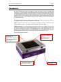
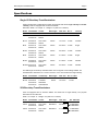
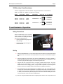
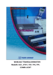
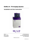
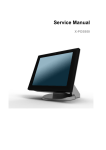
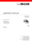
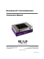
Benchtop UV Transilluminators Instruction Manual UVP, LLC 2066 W 11th Street, Upland, CA 91786 Tel: (800) 452-6788 / (909) 946-3197 Fax: (909) 946-3597 Ultra-Violet Products Ltd. Unit 1,Trinity Hall Farm Estate, Nuffield Road Cambridge CB4 1TG UK Tel: +44(0)1223-420022 / Fax: +44(0)1223-420561 Web site: www.uvp.com 81-0249-01 Rev F Benchtop UV Transilluminators Page 2 Introduction The UVP Transilluminator offers the researcher uniform and intense sources of ultraviolet light (radiation) in a compact package. The special design emits high intensity excitation UV wavelength for back-illumination of transparent fluorescent materials. The 302nm UV back-illumination provides a highly sensitive method to detect double-stranded nucleic acids that have been labeled with fluorescent dyes such as ethidium bromide or acridine orange. Single stranded nucleic acids may be detected, but with a lower excitation wavelength more sensitive for nucleic acid visualization than the 365nm model. The transilluminator is uniquely designed with increased UV intensity and uniformity, instant on capabilities, no lamp flicker and reduced electrical consumption. NOTE: Though the manual refers to the midrange UV waveband as 302nm, others refer to this region as 300nm or 312nm. The spectral output of all these regions is the same. A Word of Caution: UV Transilluminators are powerful sources of UV radiation that will cause damage to unprotected eyes and skin. Before operating any unit, be sure all personnel in the area are properly protected. If not using the transilluminator with an imaging system darkroom, a UV Blocking Cover should be attached to the transilluminator. Even though this cover blocks the ultraviolet radiation emitted by the unit, UV Blocking Eyewear should be worn as well. UVP UV Transilluminator features: UVP’s long life filters are available in a variety of filter sizes from 15 x 15cm to 25 x 26cm UV Blocking Cover may be included with the transilluminator. The cover is hinged and adjustable to varying heights Select models include a control knob for selection of wavelengths or intensity Power switch Benchtop UV Transilluminators Page 3 Specifications Single UV Benchtop Transilluminators Single UV Benchtop Transilluminator models are designed with either single intensity or variable intensity. Units are equipped with an electronic ballast. Dimension: Width: 14” x Depth: 11” x Height: 4.8” (356 x 279 x 122mm) Model Part Number Volt/Hz Wavelength Filter Size No. of Tubes Intensity Style M-15 95-0455-01 95-0455-02 100-115/60 230/50 302nm 15 x 15cm 4 x 8W Single M-15V 95-0456-01 95-0456-02 100-115/60 230/50 302nm 15 x 15cm 4 x 8W Variable M-20 95-0447-01 95-0447-02 100-115/60 230/50 302nm 20 x 20cm 4 x 8W Single M-20V 95-0452-01 95-0452-02 100-115/60 230/50 302nm 20 x 20cm 4 x 8W Variable M-26 95-0457-01 95-0457-02 100-115/60 230/50 302nm 21 x 26cm 4 x 8W Single M-26V 95-0458-01 95-0458-02 100-115/60 230/50 302nm 21 x 26cm 4 x 8W Variable M-26XV 95-0413-01 95-0413-02 100-115/60 230/50 302nm 25 x 26cm 4 x 8W Variable The mini single UV Benchtop Transilluminator uses a magnetic core/coil design ballast. The transilluminator dimensions are: 7.25”D x 10.25”W x 4.5”H. This model has a single intensity. Model Part Number Volt/Hz/Amp M-10E 95-0180-01 95-0180-02 95-0180-03 Wavelength 115/60/0.7 230/50/0.6 100/50-60/0.8 302nm Filter Size 10 x 10cm No. of Tubes 5 x 6W 2UV Benchtop Transilluminators Units are equipped with an electronic ballast. This model has a single intensity. The physical dimensions of all models are: Width: 14” x Depth: 11” x Height: 4.8” (356 x 279 x 122mm) Model Part Number Volt/Hz Wavelength Filter Size #of Tubes/UV LM-20 95-0449-01 95-0449-02 100-115/60 230/50 302/365nm 20 x 20cm 4 x 8W/302nm 4 x 8W/365nm LM-26 95-0459-01 95-0459-02 100-115/60 230/50 302/365nm 21 x 26cm 4 x 8W/302nm 4 x 8W/365nm Benchtop UV Transilluminators Page 4 3UV Benchtop Transilluminators Units are equipped with an electronic ballast. The physical dimensions of all models are: Width: 14” x Depth: 11” x Height: 5.4” (356 x 279 x 137mm) Model Part Number Volt/Hz Wavelength Filter Size No. of Tubes/UV LMS-20 LMS-20 95-0417-01 95-0417-02 115/60 230/50 302/365/254nm 20 x 20cm 4 x 8W/302nm 4 x 8W/365nm 4 x 8W/254nm LMS-26 LMS-26 95-0414-01 95-0414-02 115/60 230/50 302/365/254nm 21 x 26cm 4 x 8W/302nm 4 x 8W/365nm 4 x 8W/254nm Transilluminator Operation Safety Precautions When the UV Blocking Cover is not being used, UV light may escape through the holes dedicated to accepting the bracket pins of the UV Blocking Cover. Remove the black safety plugs from their package Insert the safety plugs through the holes as shown. Safety Plug Set-Up Place the transilluminator on a level work surface. Be sure that an air space exists around the bottom of the work surface. This space allows for the proper air circulation through the unit. Plug the female end of the power cord into the transilluminator. For 230 volt models, or those requiring special power cord connectors, ensure that the proper configuration of male connector or plug has been properly connected to the power cord. Plug the male end of the power cord into a properly grounded electrical outlet. The proper voltage of the transilluminator is found on the product information label. If using the transilluminator with an imaging system, a jumper cable is required for connecting to the darkroom. Refer to the imaging system documentation for additional instructions. The transilluminator may be equipped with a UV Blocking Cover. This cover allows the user to safely view and work with the gel/sample on the glass surface while the transilluminator is on (be sure to wear protective gloves when working with the gel/sample during this process). To install, remove the brown protective paper from the cover. Insert the bracket pins on the cover into the holes on the front of the transilluminator. If you are not using the transilluminator with an imaging system darkroom, do not operate the unit Benchtop UV Transilluminators Page 5 without securing the cover. If the cover is missing, a UV Blocking Faceshield must be worn to avoid UV exposure to the skin. UV Blocking Eyewear should be worn even with the cover in place to avoid accidental UV exposure. Using the Transilluminator Place gel/sample on the filter area. It is recommended to place the gels on a Gel-Tray to protect the filter surface from cuts and scratches. It is recommended that gloves be worn to avoid contact with gel and staining agents. Press the ON/OFF switch to ON. The UV tubes within the unit should be glowing beneath the filter. If using the transilluminator with an imaging system, the system’s main power is required to be in the ON position. When using a transilluminator with multiple UV wavelengths, dial the knob to the appropriate wavelength setting. When using the Variable Intensity models, use the variable intensity settings as follows: High: allows for UV excitation of fluorophores on gels for routine photography and for excitation of gels with low sample concentration Medium: Excellent for viewing and quick single-band excision Low: Allows for positioning and preparation of gels, excising multiple bands and focusing for photography The UV Blocking Cover, optionally installed during setup, is adjustable to varying angles to provide easier access to the filter surface. To adjust the angle, rotate the Phillips head screws (located on the left sides of the cover’s hinges) clockwise until enough tension has been placed on the hinge to hold the cover at the desired angle. After viewing/photographing the sample, turn the transilluminator off. Cleaning and Care of the Transilluminator Clean unit surface with a damp soft cloth or sponge. Never use abrasive cleaners (can damage the UV filter surface). To protect the filter glass and minimize moisture and liquids on the glass, it is recommended that you use a UV transmitting Gel-Tray. Refer to the Replacement Parts for ordering information. Replacing Tubes in the Transilluminator Disconnect the transilluminator for the electrical supply. Remove the filter cover: Use a Phillips head screwdriver to remove the four screws on the sides of the unit. Lift the filter cover off the unit. Remove the reflectors on the left and right side of the unit: Slide the reflectors up out of the unit. Remove the tube: Carefully rotate the tube and slide out of the socket. Replace with a new tube by sliding the tube into the socket and rotating into place. Insert the reflectors back into place and reattach the filter cover. Benchtop UV Transilluminators Page 6 Maintenance/Repair/Technical Assistance Replacement Parts/Accessories For replacement parts or components not shown here, contach UVP Customer Service or place of purchase. Please have the transilluminator model number available when you call. Replacement Part Description Part Number Filter Assembly (M-10) Filter Assembly (M-15) Filter Assembly (M-15V) Filter Assembly (M-20) Filter Assembly (M-26) Filter Assembly (M-20V, LM-20, LMS-20) Filter Assembly (M-26V, LM-26, LMS-26) Filter Assembly (M-26XV) Cover, UV blocking (M-10E) Cover, UV blocking (all other models) UV Tube, 6 Watt, 302nm midrange (FL6E) – TM-10E UV Tube, 8 Watt, 302nm midrange (FL8E) Tube, 8 Watt, 365nm longwave UV (F8T5/BL) Tube, 8 Watt, 254nm shortwave UV Ballast, electronic (M-15, M-20, M-26, LM-20, LM-26) Ballast, (M-10E) Fuse, 2 amp, 250V, Slo-Blo (all voltages) 38-0150-01 38-0313-03 38-0313-09 38-0313-01 38-0313-02 38-0313-07 38-0313-08 38-0163-04 19-0114-01 19-0121-01 34-0044-01 34-0042-01 34-0006-01 34-0007-01 42-0068-04 (115V) 42-0068-06 (230V) 42-0067-04 (115V) 42-0067-06 (230V) 42-0005-01 56-0002-01 Accessories Description Gel-Cutter Gel-Scooper Gel-Tray, UV Transmitting, Sm. 11.5”W x 9”D (29 x 23cm) Gel-Tray, UV Transmitting, Lg. 16.5”W x 10.5”D (42 x 27cm) Gel-Tray, High Performance UV Transmitting (25 x 26cm) Gel-Ruler, UV Fluorescing Spectacles, UV Blocking Goggles, UV Blocking Faceshield, UV Blocking Part Number 85-0002-01 85-0006-01 85-0007-01 85-0005-01 38-0296-03 85-0003-01 98-0002-01 98-0002-02 98-0002-04 Ballast, electronic, variable (M-15V, M-20V, M-26V, M-26XV) Qty. Required 1 1 1 1 1 1 1 1 1 1 5 4 4 4 1 1 1 1 5 2 Benchtop UV Transilluminators Page 7 Technical Support UVP offers technical support for all of its products. If you have any questions about the product’s use or, operation, please contact UVP’s offices at the following locations. If you are in North America, South America, East Asia or Australia: If you are in Europe, Africa, the Middle East, Western Asia: Call (800) 452-6788 or (909) 946-3197 Customer Service regular business days, between 7 am and 5 pm PST Call +44(0) 1223-420022 Customer regular business days, between 9 am and 5:30 pm E-Mail: [email protected] E-Mail: [email protected] Fax Customer Service: (909) 946-3597 Fax Customer Service: +44(0)1223-420561 Write to: UVP, LLC 2066 W. 11th Street Upland, CA 91786 USA Write to: Ultra-Violet Products Ltd. Unit 1, Trinity Hall Farm Est, Nuffield Rd Cambridge CB4 1TG UK Note: A Returned Goods Authorization (RGA) number must be obtained from UVP Customer Service before returning any product. Warranty UVP, LLC warrants its Ultraviolet Transilluminators to be free of detects in materials and workmanship for a period of two (2) years from date of purchase. The foregoing warranty of UVP shall be of no force and effect if buyer has modified or damaged the product. Tubes and filters are warranted for 90 days. All warranties or merchantability and fitness for any purpose and all other warranties, expressed or implied, except those expressly set forth herein, are deemed waived and excluded. UVP’s duty under the warranty is limited to replacement and/or repair of the defective part at the option of UVP, LLC. UVP shall not be liable for any expenses or damages incurred by the purchaser except as expressly set forth herein, and in no event shall UVP be liable for any special, incidental or consequential damages of any kind. This warranty does not supersede any statutory rights that may be available in certain countries. UVP … Providing Quality Products for the Researcher Since 1932