1
Section 2: System Configurations
2.1
System configurations
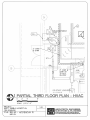
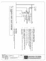
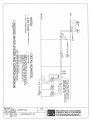
The EmpowerMR Injector System consists of the Injector Head, Remote Control, Hydraulic Controller, Electro-hydraulic
Interconnect, and AC line cords (see Fig. 2-1a, 2-1b, and 2-1c). Throughout this manual, the terms Injector Head and Injector are
used interchangeably, and the terms Remote Control and Remote are used interchangeably.
During operation, the Injector in the scanner room communicates with the Remote in the control room through the hydraulic
controller. There is a communication cable (75 feet long) routed between the Remote and the Hydraulic Controller that does not
penetrate the scanner room.
For the Hydraulic Controller, only AC Line power is required.
For the Remote, only AC Line power is required. Mounting accessories for the Remote facilitate either desktop or wall mounting.
For the Injector, a flexible Electro-hydraulic bundle (50 feet long) from the Hydraulic Controller provides the following:
• DC power via a wired cable
• Four hydraulic tubes to actuate the hydraulic cylinders
• Bidirectional optical communication link
Two system configurations are possible as shown in Fig. 2-1d and 2-1e. The only difference between the two system configurations
is the location of the Hydraulic Controller. In one configuration, the Hydraulic Controller is located in the Equipment Room and in the
other it is located in the Control Room, the Equipment Room being the preferred location due to the noise of the Hydraulic
Controller. The site survey will state where the Hydraulic Controller is to be installed.
EmpowerMR Site Survey
Document 900953-001 Rev. 02
6