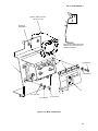
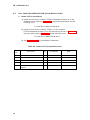
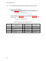
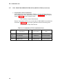
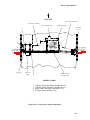
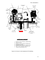
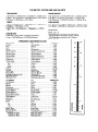
1
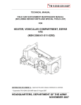
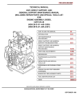
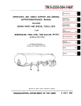
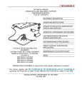
ARMY
TB 11-5830-263-20-1
MARINE CORPS
MI 08953A-35/26
TECHNICAL BULLETIN
VIS
INSTALLATION INSTRUCTIONS FOR
INTERCOMMUNICATION SET, VEHICULAR
AN/VIC-3(V)1
(NSN 5830-01-395-4177) (EIC: NA)
IN A
TANK, COMBAT, FULL TRACKED, M1A1
Approved for public release; distribution is unlimited.
HEADQUARTERS, DEPARTMENT OF THE ARMY
AND HEADQUARTERS, MARINE CORPS
1 JUNE 2000
TB 11-5830-263-20-1
LIST OF EFFECTIVE PAGES/WORK PACKAGES
Dates of issue for the original manual and changed pages/work packages are:
Original
1 June 2000
TOTAL NUMBER OF PAGES FOR FRONT AND REAR MATTER IS 12 AND TOTAL
NUMBER OF WORK PACKAGES IS 0, CONSISTING OF THE FOLLOWING:
Page/WP
No.
Title
Warnings (3 pages)
i thru iv
1 thru 39
*Change
No.
Page/WP
No.
0
0
0
0
* Zero in this column indicates an original page.
A/(B blank)
*Change
No.
TB 11-5830-263-20-1
5
SAFETY STEPS TO FOLLOW IF SOMEONE IS THE VICTIM OF
ELECTRICAL SHOCK
1
DO NOT TRY TO PULL OR GRAB THE INDIVIDUAL
2
IF POSSIBLE, TURN OFF THE ELECTRICAL POWER
3
IF YOU CANNOT TURN OFF THE ELECTRICAL POWER, PULL, PUSH,
OR LIFT THE PERSON TO SAFETY USING A DRY WOODEN POLE OR
A DRY ROPE OR SOME OTHER INSULATING MATERIAL
4
5
SEND FOR HELP AS SOON AS POSSIBLE
AFTER THE INJURED PERSON IS FREE OF CONTACT WITH THE
SOURCE OF ELECTRICAL SHOCK, MOVE THE PERSON A SHORT
DISTANCE AWAY AND IMMEDIATELY START ARTIFICIAL
RESUSCITATION
a
TB 11-5830-263-20-1
WARNING
HIGH VOLTAGE
IS USED IN THE OPERATION OF THIS EQUIPMENT.
DEATH ON CONTACT
MAY RESULT IF PERSONNEL FAIL TO OBSERVE SAFETY PRECAUTIONS.
NEVER WORK ON ELECTRONIC EQUIPMENT UNLESS THERE IS ANOTHER
PERSON NEARBY WHO IS FAMILIAR WITH THE OPERATION AND HAZARDS OF
THE EQUIPMENT AND WHO IS COMPETENT IN ADMINISTERING FIRST AID.
WHEN THE TECHNICIAN IS AIDED BY OPERATORS, HE MUST WARN THEM
ABOUT DANGEROUS AREAS.
BE CAREFUL NOT TO CONTACT HIGH-VOLTAGE CONNECTIONS OF THE AC
INPUT CONNECTIONS WHEN INSTALLING OR OPERATING THIS EQUIPMENT.
WHENEVER THE NATURE OF THE OPERATION PERMITS, KEEP ONE HAND-AWAY
FROM THE EQUIPMENT TO REDUCE THE HAZARD OF CURRENT FLOWING
THROUGH VITAL ORGANS OF THE BODY.
WARNING
DO NOT BE MISLED BY THE TERM "LOW VOLTAGE". POTENTIALS AS LOW AS 30
VOLTS MAY CAUSE DEATH UNDER CERTAIN CONDITIONS.
FOR ARTIFICIAL RESPIRATION, REFER TO FM 21-11.
WARNING
WHEN LISTENING TO THE VIS RADIO HEADSET WITH THE OPERATOR VOLUME
CONTROLS SETTING IN THE RED ZONE CLICK STOP AT A FULL ON VOLUME
SETTING, EXTREME CAUTION MUST BE EXERCISED TO PREVENT
NOISE-INDUCED HEARING LOSS. EXPOSURES TO RADIO SIGNALS IN THE FULL
ON POSITION BEYOND 45 SECONDS MAY CAUSE HEARING LOSS. ANY
PROLONGED EXPOSURE IN THE FULL ON VOLUME CONTROL SETTING
REQUIRES THE USE OF A SINGLE HEARING PROTECTIVE DEVICE IN EACH EAR.
b
TB 11-5830-263-20-1
WARNING
ALKALINE BATTERIES CONTAIN CAUSTIC KOH ELECTROLYTE, WHICH MAY LEAK
IF THE BATTERY IS ABUSED. KOH IS A STRONG ALKALI SIMILAR TO CAUSTIC
SODA (SODIUM HYDROXIDE). SERIOUS CHEMICAL BURNS CAN RESULT IF
ELECTROLYTE COMES INTO CONTACT WITH THE SKIN OR EYES. IF THE
BATTERY ELECTROLYTE GETS INTO YOUR EYES, IT CAN CAUSE SEVERE
DAMAGE AND/OR BLINDNESS.
DO NOT TRY TO NEUTRALIZE CAUSTIC ELECTROLYTE WITH VINEGAR OR ANY
OTHER ACIDIC SOLUTIONS. NEUTRALIZATION WILL DO MORE HARM THAN
GOOD, AS IT WILL TRAP CAUSTIC UNDER THE SKIN, PREVENTING IT FROM
COMING OUT. FLUSH WITH COPIOUS AMOUNTS OF COOL WATER.
c/(d blank)
TB 11-5830-263-20-1
MI 08953A-35/26
TECHNICAL BULLETIN
NO. 11-5830-263-20-1
MI 08953A-35/26
HEADQUARTERS, DEPARTMENT OF THE ARMY
AND HEADQUARTERS, MARINE CORPS
WASHINGTON, D.C., 1 JUNE 2000
INSTALLATION INSTRUCTIONS FOR
INTERCOMMUNICATION SET, VEHICULAR
AN/VIC-3(V)1
(NSN 5830-01-395-4177) (EIC: NA)
IN A
TANK, COMBAT, FULL TRACKED, M1A1
REPORTING ERRORS AND RECOMMENDING IMPROVEMENTS
You can help improve this manual. If you find any mistakes, or if you know of a way to improve the
procedures, please let us know. Mail your letter, DA Form 2028 (Recommended Changes to
Publications and Blank Forms) or DA Form 2028-2 located in back of this manual direct to:
Commander, US Army Communications-Electronics Command and Fort Monmouth, ATTN:
AMSEL-LC-LEO-D-CS-CFO, Fort Monmouth, New Jersey 07703-5007. The fax number is
732-532-1413, DSN 992-1413. You may also email
your
recommendations
to
[email protected]
Marine Corps units, submit NAVMC 10772 (Recommended Changes to Technical Publications) to:
Commanding General, Marine Corps Logistics Base (Code 850), Albany, Georgia 31704-5000.
In either case a reply will be furnished direct to you.
APPROVED FOR PUBLIC RELEASE; DISTRIBUTION IS UNLIMITED.
TABLE OF CONTENTS
SUBJECT
PAGE
SECTION I. INTRODUCTION .......................................................................... 1
1.1
SCOPE .............................................................................................. 1
1.2
GENERAL INFORMATION .................................................................... 1
1.3
CONSOLIDATED INDEX OF ARMY PUBLICATIONS ................................ 2
1.4
MAINTENANCE FORMS, RECORDS, AND REPORTS .............................. 2
1.5
CORROSION PREVENTION AND CONTROL .......................................... 2
SECTION II. PREPARATION FOR INSTALLATION............................................ 3
2.1
PREPARING THE VEHICLE ................................................................. 3
2.2
EXPENDABLE/DURABLE ITEMS ........................................................... 4
2.3
TOOLS AND TEST, MEASUREMENT AND DIAGNOSTIC EQUIPMENT....... 4
2.4
VIS COMPONENTS (PARTS LIST) ........................................................ 5
2.5
PRE-INSTALLATION STEPS AND PROCEDURES ................................... 8
i
TB 11-5830-263-20-1
TABLE OF CONTENTS (continued)
SUBJECT
PAGE
SECTION III. FFCS AND RIT CREW STATION/RADIO SWITCH SETTING
PROCEDURES .............................................................................................. 9
3.1
FFCS CREW STATION ADDRESS SWITCH SETTING PROCEDURES ....... 9
3.2
RIT RADIO SELECTION SWITCH SETTING PROCEDURES ..................... 9
SECTION IV. INSTALLATION INSTRUCTIONS ................................................. 10
4.1
EQUIPMENT LOCATION AND SYSTEM CONFIGURATION DIAGRAMS ...... 10
4.2
MASTER CONTROL STATION (MCS) INSTALLATION ............................. 12
4.3
FULL FUNCTION CREW STATION (FFCS) INSTALLATION ...................... 14
4.4
RADIO INTERFACE TERMINAL (RIT) INSTALLATION ............................. 22
4.5
MONITOR ONLY STATION (MOS) INSTALLATION .................................. 22
4.6
LOUDSPEAKER (LS) INSTALLATION .................................................... 22
4.7
VIS CABLING INSTALLATION .............................................................. 24
SECTION V. POST-INSTALLATION ................................................................ 34
5.1
POST-INSTALLATION CHECKOUT PROCEDURES ................................. 34
5.2
POST-INSTALLATION OPERABILITY VERIFICATION PROCEDURES ........ 34
APPENDIX A - REFERENCES ......................................................................... 37
A-1.
SCOPE .............................................................................................. 37
A-2.
FORMS ............................................................................................. 37
A-3.
TECHNICAL MANUALS ....................................................................... 37
A-4.
MISCELLANEOUS PUBLICATIONS ....................................................... 38
ii
TB 11-5830-263-20-1
LIST OF TABLES
Number
Table
Table
Table
Table
Table
Table
Table
Table
Table
2-1.
2-2.
2-3.
2-4.
4-1.
4-2.
4-3.
4-4.
4-5.
Title
Page
Retained Items List ......................................................................... 3
Expendable/Durable Items................................................................ 4
Tools and Test, Measurement and Diagnostic Equipment...................... 4
VIS Components (Parts List) ............................................................. 5
MCS Installation Parts ..................................................................... 12
Loader's FFCS Installation Parts ....................................................... 14
Gunner's FFCS Installation Parts....................................................... 16
Commander's FFCS Installation Parts ................................................ 18
Driver's FFCS Installation Parts ........................................................ 20
LIST OF FIGURES
Number
Figure
Figure
Figure
Figure
Figure
Figure
Figure
Figure
Figure
Figure
Figure
Figure
Figure
Figure
Title
Page
2-1. Illustrated Parts List ....................................................................... 6
2-2. Illustrated Parts List - Cables........................................................... 7
3-1. FFCS Crew Station Address Switch .................................................. 9
4-1. Equipment Location Diagram ........................................................... 10
4-2. System Configuration Diagram ......................................................... 11
4-3. MCS Installation ............................................................................ 13
4-4. Loader's FFCS Installation .............................................................. 15
4-5. Gunner's FFCS Installation .............................................................. 17
4-6. Commander's FFCS Installation ....................................................... 19
4-7. Driver's FFCS Installation................................................................ 21
4-8. MCS, Loader's FFCS and Loudspeaker Cabling.................................. 25
4-9. Turret Floor Cable Installation.......................................................... 29
4-10. Gunner's and Commander's FFCS Cabling....................................... 31
4-11. Driver's FFCS Cabling................................................................... 33
iii /iv blank
TB 11-5830-263-20-1
Section I. INTRODUCTION
1.1
SCOPE
This technical bulletin provides installation instructions for the Intercommunication
Set, Vehicular AN/VIC-3(V), hereinafter referred to by its common name, VIS
(Vehicular Intercommunication System). There are many current and future variations
of this system, e.g. AN/VIC-3(V)1, (V)2, etc., designed for specific vehicles and/or
platforms, each with its own unique technical bulletin. The version this technical
bulletin covers and the vehicle/platform it is being installed in is:
“AN/VIC-3(V)1”
into the
"TANK, COMBAT, FULL TRACKED, M1A1"
The information contained in this technical bulletin is the official authorization to
perform the installation of the VIS at the Unit Maintenance Level.
1.2
GENERAL INFORMATION
a. Reference Publications
There are two manuals associated with the VIS, TM 11-5830-263-10
Operator’s Manual, and TM 11-5830-263-20&P Unit Maintenance Manual
(Including Repair Parts and Special Tools List (RPSTL)). Additionally, for
periodic updated information on the VIS and its specific components refer
to the CECOM Supply Bulletin and The Preventive Maintenance Monthly.
b. Purpose of Equipment
The AN/VIC-3(V) or VIS is an intercommunication and radio-control system
designed for ground mobile combat vehicles. Digital audio enhances
speech quality and intelligibility. Headsets that incorporate active noise
reduction (ANR) circuitry increase the effectiveness of vehicle
communications. They offer increased hearing protection in the noisy
environment of combat vehicles.
c. Equipment Components
The AN/VIC-3(V) or VIS versions are configured for specific vehicles
and/or platforms. When installed in a vehicle/platform it loses its identity.
VIS is designed to replace the AN/VIC-1 or -2, in some cases utilizing the
existing mounting hardware and brackets used by the AN/VIC-1 or -2. VIS
consists of LRU’s (Line Replaceable Units (Boxes)) (the type and quantity
of which vary depending upon the specific vehicle and/or platform), various
types of cables (highway, power, alarm, etc.), headsets (the type and
quantity of which vary depending upon the specific vehicle and/or
platform), brackets, and mounting hardware (nuts, bolts, screws, etc.) for
securing both the LRU’s and brackets. Every vehicle/platform contains one
Master Control Station (MCS), a number of Full Function Crew Stations
(FFCS), and a Permanent Magnet Loudspeaker (LS). Depending upon the
vehicle/platform VIS is being installed in, it may also contain Radio
Interface Terminal(s) (RIT) and Monitor Only Station(s) (MOS).
1
TB 11-5830-263-20-1
1.3
CONSOLIDATED INDEX OF ARMY PUBLICATIONS
Refer to the latest issue of DA PAM 25-30 to determine whether there are new
editions, changes, or additional publications pertaining to the equipment.
1.4
MAINTENANCE FORMS, RECORDS, AND REPORTS
a. Reports of Maintenance and Unsatisfactory Equipment
Department of the Army forms and procedures used for equipment
maintenance will be those prescribed by DA Pam 738-750, as contained in
Maintenance Management Update.
Marine Corps maintenance records will be maintained in accordance with
TM-4700-15/1, Ground Equipment Record Procedures.
b. Reporting of Item and Packaging Deficiencies
Fill out and forward SF364 (Report of Discrepancy (ROD)) as prescribed in
AR 735-11-2/DLAR 4140.55/SECNAVINST 4355.18/AFR400-54/MCO
4430.3J.
c. Transportation Discrepancy Report (TDR)(SF361)
Fill out and forward Transportation Discrepancy Report (TDR) (SF361) as
prescribed in AR 55-38/NAVSUPINST 4610.33C/AFR 75-18/MCO
P4610.19D/DLAR 4500.15.
.
1.5
CORROSION PREVENTION AND CONTROL
Corrosion Prevention and Control (CPC) of Army materiel is a continuing concern. It
is important that any corrosion problems with this item be reported so that the
problems can be corrected and improvements can be made to prevent the problem in
the future.
While corrosion is typically associated with rusting of metals, it can also include
deterioration of other materials, such as rubber and plastic. Unusual cracking,
softening, swelling, or breaking of these materials may be a corrosion problem.
If a corrosion problem is identified, it can be reported using SF 368, Product Quality
Deficiency Report (QDR). Use of key words such as “corrosion”, “rust”, “deterioration”,
or “cracking” will ensure that the information is identified as a CPC problem.
The form should be submitted to the address specified in DA PAM 738-750,
Functional User’s Manual for the Maintenance Management System (TAMMS).
2
TB 11-5830-263-20-1
SECTION II. PREPARATION FOR INSTALLATION
Prior to preparing the vehicle for installation or actually installing the VIS this
technical bulletin should be read in its entirety.
2.1
PREPARING THE VEHICLE
a. To prepare the vehicle for installation, ensure that the site includes
adequate lighting. Inspect the vehicle for damage that could effect
installation. Have any such damage repaired before installing VIS.
b. Installing the AN/VIC-3(V) into the vehicle/platform sometimes requires
retaining the existing mounting hardware (and brackets) that were used to
secure the AN/VIC-1 or -2 systems being replaced. Table 2-1 lists the
items, if any, to be retained prior to installation.
Table 2-1. Retained Items List
Item Description and Part Number
Quantity
(TBD)
3
TB 11-5830-263-20-1
2.2
EXPENDABLE/DURABLE ITEMS
Table 2-2 lists the Expendable/Durable items the unit or retrofit/installation team
should have on hand prior to the installation of the VIS. Refer to the VIS Operator’s
TM for specific uses for these items not cited in this technical bulletin.
Table 2-2. Expendable/Durable Items
Item
National Stock
No.
Number
1.
6850-00-973-9091
Fluid, Penetrating, (01267) DUOL
CN
2.
7920-00-044-9281
Cloth, Cleaning, (81349), MIL-C-85043
BX
3.
6810-00-292-9625
Degreasing Solvent, (83574) PR146BLUE
QT
4.
6850-00-664-4959
Silicone Compound, (71984), DC 6
GL
5.
7930-00-282-9699
Detergent, General Purpose, (81349),
MIL-D-16791
GL
7.
6810-01-075-5546
Isopropyl Alcohol
CN
2.3
Description
U/M
TOOLS AND TEST, MEASUREMENT AND DIAGNOSTIC EQUIPMENT
(TMDE)
Table 2-3 lists the tools, and if required, the TMDE needed for installation of the VIS.
Table 2-3. Tools and Test, Measurement and Diagnostic Equipment
NOMENCLATURE
NSN
Screwdriver, No. 3 Point Phillips, 4 in.
5120-00-234-8912
1
Tool Kit TK101 /G
Pliers, Slip Joint, 1 1/2 in.
5180-00-064-5178
5120-01-336-5636
1
1
4
QUANTITY
TB 11-5830-263-20-1
2.4
VIS COMPONENTS (PARTS LIST)
Table 2-4 lists, with quantities, the Line Replaceable Units (LRU’s)(Boxes), Headsets,
Cables, Brackets, Mounting Hardware and any other items that will be installed in the
vehicle/platform covered by this technical bulletin. This table will be used as a
checklist when the pre-installation inventory is conducted. Illustrations (Figures)
referenced in Table 2-4 are on the pages immediately following the table. It should
be noted that this table does not list parts that need to be retained for reuse from
removing the previous AN/VIC-1 or -2 system. Refer to Table 2-1 for those items.
Table 2-4. VIS Components (Parts List)
NSN
5895-01-382-3221
5830-01-382-3218
5965-01-382-3222
5965-01-397-7542
5965-01-398-1551
5965-01-397-7544
8470-01-389-3815
8470-01-389-3821
5995-01-392-7323
5995-01-392-6203
5995-01-392-9114
5995-01-392-7352
5995-01-392-7364
5995-01-386-9109
5995-01-392-7363
5995-01-392-7319
5995-01-392-7320
5995-01-393-7694
5995-01-392-0216
Not applicable
Not applicable
Not applicable
Not applicable
5365-00-783-9035
5310-00-081-4219
5305-00-984-6210
5310-00-576-5752
5310-00-550-1130
5310-00-167-0721
5310-00-103-6042
5310-00-880-7746
5305-00-225-3839
5975-00-133-8696
Not applicable
ITEM DESCRIPTION
AND PART NUMBER
QTY
IN VIS
SMR
CODE
Master Control Station (MCS), A3205747
Full Function Crew Station (FFCS), A3205746
(Driver’s, Spare, FSSgt, FSO, and FSS)
Loudspeaker, Permanent Magnet, LS-688, A3206080
Headset, CVC, Small, A3206101-1
Headset, CVC, Medium, A3206101-2
Headset, CVC, Large, A3206101-3
ACVCH, Small/Medium
ACVCH, Large
Cable Assembly, Power, A3206017-7
Cable Assembly, Highway, A3206018-8
Cable Assembly, Highway, A3206018-20
Cable Assembly, Highway, A3206018-21
Cable Assembly, R/T, A3206019-9
Cable Assembly, Bailout, A3206020
Cable Assembly, Alarm, A3206021-19
Cable Assembly, Highway/Vehicle, A3206081-3-3
Cable Assembly, Highway/Vehicle, A3206102-4-4
Cable Assembly, Loudspeaker, A3206193-6
Cable Assembly, Loudspeaker, A3206193-30
Cover Assembly, MCS, A3206103
Bracket, Mounting, MCS, A3206200
Plate, Mounting, A3206395
Bracket, Loader's FFCS/Loudspeaker, A3206396
Strap, Cable, A3206207
Washer, Flat, MS27183-12
Screw, Pan Head, MS35206-263
Washer, Lock, MS35333-39
Washer, Lock, MS35333-40
Washer, Lock, MS35333-41
Washer, Flat, MS51412-4A
Nut, Hexagon, MS51968-5
Bolt, Machine, MS90725-8
Strap, Tiedown, MS3367-6-9
Decal, Reference, A3206410
1
4
PAODD
PAODD
2-1, 1
2-1, 2
1
PAOOO
PAOOO
PAOOO
PAOOO
2-1,
2-1,
2-1,
2-1,
3
4
4
4
PAOZZ
PAOZZ
PAOZZ
PAOZZ
PAOZZ
PAOZZ
PAOZZ
PAOZZ
PAOZZ
PAOZZ
PAOZZ
PAOZZ
PAOZZ
PAOZZ
PAOZZ
PAOZZ
PAOZZ
PAOZZ
PAOZZ
PAOZZ
PAOZZ
PAOZZ
PAOZZ
PAOZZ
PAOZZ
XBOZZ
2-2,
2-2,
2-2,
2-2,
2-2,
2-2,
2-2,
2-1,
2-2,
2-2,
2-2,
5
6
6
6
7
8
9
10
10
11
11
4
Total
FIGURE *,
ITEM NO.
4**
Total
1
1
1
1
2
4
1
1
1
1
1
1
1
1
1
6 ft
8
4
4
4
8
4
8
4
12
1
* See Figures 2-1 and 2-2 for illustration of the referenced part(s).
** Marine Corps only, substitute Advanced Combat Vehicle Crewman's Helmet
(ACVCH) for CVC Headset. There is no illustration for ACVCH.
5
TB 11-5830-263-20-1
1
2
3
4
Figure 2-1. Illustrated Parts List
6
TB 11-5830-263-20-1
6
5
P2
P1
P1
P2
8
7
P2
P1
P1
9
P2
10
P2
P1
P2
P1
P3
11
P1
P2
Figure 2-2. Illustrated Parts List - Cables
7
TB 11-5830-263-20-1
2.5
PRE-INSTALLATION STEPS AND PROCEDURES
a. Read the technical bulletin in its entirety prior to performing any
designated tasks.
b. Ensure that the expendable/durable items identified in Table 2-2, and the
tools and TMDE, if required, identified in Table 2-3 are available for use.
c. Remove the AN/VIC-1 or -2 system, if present, in preparation of installing
the VIS. Refer to Table 2-1 to determine, what, if any, AN/VIC-1 or -2
components need to be retained.
d. Unpack VIS equipment/components and conduct a complete physical
inventory of the items using Table 2-4 as a checklist. Be sure to inspect
packaging for evidence of damage and examine each item for damage. If
any discrepancies are noted refer to paragraphs 1.4 and 1.5 for the
appropriate maintenance documentation to fill out.
e. Examine the decal provided with the kit. Identify the number of FFCSs and
RIT’s. Mark the FFCSs and RITs numerically to match the decal (a piece
of tape is recommended).
f.
For each FFCS, set the Crew Station Address Switch to the number
marked on it. For each RIT, set the Radio Selection Switch to the
appropriate radio setting. Refer to Section III for the appropriate
procedures to accomplish these tasks.
g. You are now ready to install the VIS into the vehicle/platform.
8
TB 11-5830-263-20-1
SECTION III. FFCS AND RIT CREW STATION/RADIO SWITCH
SETTING PROCEDURES
3.1
FFCS CREW STATION ADDRESS SWITCH SETTING PROCEDURES
Perform the following procedure to change the FFCS Crew Station Address switch setting located
on the bottom of the FFCS. Crew Station Addresses are as shown on the Decal.
FFCS
M1A1 ABRAMS FULL TRACKED
COMBAT TANK Decal
Cover
Rotation
1
FFCS
2
3
Crew Station
Address Switch
4
5
8
7
6
COMMANDER
LOADER
GUNNER
DRIVER
I.D.
NUMBER
1
2
3
4
Figure 3-1. FFCS Crew Station Address Switch
a. Rotate switch cover screw counterclockwise (ccw) and remove.
b. Using a jeweler’s screwdriver, rotate the adjustment screw ccw, until stop is reached.
This is the setting for Crew Station #1.
c.
Each click of the switch in a clockwise direction changes the address by one position.
For example, with the switch in the full ccw position (Crew Station #1), turning the
switch two clicks in a clockwise direction will set the FFCS to Crew Station #3.
d. The address switch has 8 positions. Crew Station settings are numbered 1 through
6. Position 7 on the switch is the same as position 6. Position 8 on the switch is
normally used for testing, however, if the MCS is not functioning correctly, e.g., loss
of timing signal (sync pulse), but is supplying power to the rest of the system, setting
the switch to position 8 will result in the FFCS putting out a timing signal like the
MCS.
e. When the correct Crew Station address has been set replace switch cover screw and
hand tighten.
3.2
RIT RADIO SELECTION SWITCH SETTING PROCEDURES
This vehicle does not contain any RITs.
9
TB 11-5830-263-20-1
SECTION IV. INSTALLATION INSTRUCTIONS
4.1
EQUIPMENT LOCATION AND SYSTEM CONFIGURATION DIAGRAMS
The Equipment Location and the System Configuration Diagrams are shown in
Figures 4-1 and 4-2.
COMMANDER'S
FFCS
A3205746
GUNNER'S FFCS
A3205746
MCS
A3205747
LOUDSPEAKER
A3206080
LOADER'S FFCS
A3205746
DRIVER’S FFCS
A3205746
2X MOUNTING TRAYS (SINGARS)
(REFERENCE)
Figure 4-1. Equipment Location Diagram
10
TB 11-5830-263-20-1
2
1
STATION
MCS
P1
A3205747
COMMANDER
GUNNER
FFCS 1
A3205746
FFCS 3
A3205746
P2
P2
EXTERNAL
LINE
LOUD
SPEAKER
ALARM
STATION
P1
P1
POWER
P1
P1
P2
P1
P2
3
P1
4
( 3 FT)
P6
P2
LOADER
FFCS 2
A3205746
8
P3
(1W102-9
VEHICLE
ALARM
CABLE)
P1
2
( 3 FT)
7
P2
SLIP
RING
LOUDSPEAKER
A3206080
9
P1
5
J6
J5
6
(4 FT)
P1
RT-B
RT-A
(2W110)
P2
P2
P2
DRIVER
A4J4 A4J2
CABLE PART NUMBERS
(SINCGARS)
1.
2.
3.
4.
5.
6.
7.
8.
9
A3206018-21
A3206018-8
A3206018-20
A3206081-3-3
A3206102-4-4
A3206017-7
A3206193-6 or-30
A3206021-19
A3206019-9
FROM
Cable
#
9
9
6
7
8
1
2
3
4
Cable
Conn.
P1
P1
P1
P1
P1
P2
P2
P2
P3
5
5
4
P1
P2
P1
Unit
MCS
MCS
MCS
MCS
MCS
MCS
FFCS #1
FFCS #3
FFCS #2
Unit Conn.
Radio A
Radio B
Power
Loudspeaker
Alarm
Top Station
Left
Left
Left
Cable
Conn.
P2
P2
P2
P2
P2
P1
P1
P1
P1
2W110
FFCS #4
Slip Ring
Interface Cable
From Slip Ring J5
Left
From Slip Ring J6
P3
P1
P2
FFCS 4
A3205746
(4 FT)
A4J1 A4J3
P2
TO
Unit
Radio Tray
Radio Tray
Radio Tray
Loudspeaker
1W102-9
FFCS #1
FFCS #3
FFCS #2
Slip Ring
Interface Cable
FFCS #4
2W110
MCS
P3
Unit Conn.
A4J3
A4J4
A4J2
P6
Right
Right
Right
To Slip Ring J6
Right
To Slip Ring J5
Bottom Station
Figure 4-2. System Configuration Diagram
11
TB 11-5830-263-20-1
4.2
MASTER CONTROL STATION (MCS) INSTALLATION
Note
Tag RF cables prior to removing from MCS Mounting Bracket.
a. Install and secure the MCS Mounting Bracket (5) to existing standoffs
using existing hardware. While attaching the MCS mounting bracket use
caution not to damage radio cable connectors against rear wall of turret.
Transfer cables attached to back of previous mounting bracket to back of
new MCS mounting bracket.
b. Install and secure the MCS (1) to MCS mounting bracket (5) as far to the
right as possible. Secure using Items 2, 3 and 4 from Table 4-1 in the
sequence(s) shown in Figure 4-3 and the following tools:
1/2 Inch Box or Open End Wrench
c. Install and secure MCS Cover Assembly (6) using items 7 and 8 from Table
4-1 in the sequence(s) shown in Figure 4-3 and the following tools
Phillips Head Screwdriver
d. Place the M1A1 Main Battle Tank decal (Item 9), on the MCS Cover
Assembly (6) as shown in Figure 4-3.
Table 4-1. MCS Installation Parts
Item
No.
12
Description
Qty
Part Number
NSN
1
MCS
1
A3205747
5895-01-382-3221
2
Nut, Hexagon
4
MS51968-5
5310-00-880-7746
3
Washer, Lock
4
MS35333-41
5310-00-167-0721
4
Washer, Flat
4
MS27183-12
5310-00-081-4219
5
MCS Mounting Bracket
1
A3206200
Not Applicable
6
MCS Cover Assembly
1
A3206103
Not Applicable
7
Screw, Pan Head
4
MS35206-263
5305-00-984-6210
8
Washer, Lock
4
MS35333-39
5310-00-576-5752
9
Decal, M1A1 Main Battle Tank
1
A3206410
Not Applicable
TB 11-5830-263-20-1
J2-F
(EAPU, Marine Corps
vehicles only)
RT-B
J1-F
RT-A
(Existing
hardware)
Side view of MCS Mounting
Bracket (5) showing radio
cable connectors
1
7 (4 places)
6
5
8 (4 places)
.3
3.3
9
4 (4 places)
3 (4 places)
2 (4 places)
Figure 4-3. MCS Installation
13
TB 11-5830-263-20-1
4.3
FULL FUNCTION CREW STATION (FFCS) INSTALLATION
a. Loader's FFCS Installation
(1) Install and secure the Loader's FFCS/Loudspeaker bracket (5) to the
roadside wall as shown in Figure 4-4, using existing hardware and the
following tools:
1/2 Inch Box or Open End Wrench
(2) Install and secure the Loader's FFCS (1) to the Loader's
FFCS/Loudspeaker bracket (5) in the sequence(s) shown in Figure 4-4
using the parts listed in Table 4-2 and the following tools:
1/2 Inch Box or Open End Wrench
(3) See Paragraph 4.6 for Loudspeaker Installation.
Table 4-2. Loader's FFCS Installation Parts
Item
No.
14
Description
Qty
Part Number
NSN
1
FFCS
1
A3205746
5830-01-382-3218
2
Nut, Hexagon
2
MS51968-5
5310-00-880-7746
3
Washer, Lock
2
MS35333-41
5310-00-167-0721
4
Washer, Flat
2
MS27183-12
5310-00-081-4219
5
Loader's FFCS/Loudspeaker
Bracket
1
A3206396
Not Applicable
TB 11-5830-263-20-1
(Loudspeaker - See
Paragraph 4.6)
(Existing Hardware)
5
1
4 (2 places)
3 (2 places)
2 (2 places)
Figure 4-4. Loader's FFCS Installation
15
TB 11-5830-263-20-1
4.3
FULL FUNCTION CREW STATION (FFCS) INSTALLATION (Continued)
b. Gunner's FFCS Installation
Install and secure the Gunner's Mounting Plate (5) to the curbside wall as
shown in Figure 4-5, using existing hardware and the following tools:
1/2 Inch Box or Open End Wrench
Install and secure Gunner's FFCS (1) on the Mounting Plate (5) in the
sequence(s) shown in Figure 4-5 using the parts listed in Table 4-3 and the
following tools:
1/2 Inch Box or Open End Wrench
Table 4-3. Gunner's FFCS Installation Parts
Item No.
16
Description
Qty
Part Number
NSN
1
FFCS
1
A3205746
5830-01-382-3218
2
Nut, Hexagon
2
MS51968-5
5310-00-880-7746
3
Washer, Lock
2
MS35333-41
5310-00-167-0721
4
Washer, Flat
2
MS27183-12
5310-00-081-4219
5
Plate, Mounting
1
A3206395
Not Applicable
TB 11-5830-263-20-1
(Existing
hardware)
1
5
4 (2 places)
3 (2 places)
2 (2 places)
Figure 4-5. Gunner's FFCS Installation
17
TB 11-5830-263-20-1
4.3
FULL FUNCTION CREW STATION (FFCS) INSTALLATION (Continued)
c. Commander's FFCS Installation
Install and secure the Commander's FFCS (1) on the existing bracket on
the curbside wall in the sequence(s) shown in Figures 4-6 using the parts
listed in Table 4-4 and the following tools:
7/16 Inch Box or Open End Wrench
Secure Commander's FFCS (1) to side tabs of SINCGARS Control-Monitor
as shown in Figure 4-6 using existing hardware and the following tools.
1/2 Inch Box or Open End Wrench
Table 4-4. Commander's FFCS Installation Parts
Item No.
18
Description
Qty
Part Number
NSN
1
FFCS
1
A3205746
5830-01-382-3218
2
Bolt, Machine
2
MS90725-8
5305-00-225-3839
3
Washer, Lock
2
MS35333-40
5310-00-550-1130
4
Washer, Flat
2
MS51412-4A
5310-00-103-6042
TB 11-5830-263-20-1
(SINCGARS
Control Monitor)
(Existing
hardware)
1
4 (2 places)
3 (2 places)
2 (2 places)
Figure 4-6. Commander's FFCS Installation
19
TB 11-5830-263-20-1
4.3
FULL FUNCTION CREW STATION (FFCS) INSTALLATION (Continued)
d. Driver's FFCS Installation
Install and secure the Driver's FFCS on the Driver's right hand console in
the sequence(s) shown in Figure 4-7 using the parts listed in Table 4-5 and
the following tools:
7/16 Inch Socket Wrench
Table 4-5. Driver's FFCS Installation Parts
Item
No.
20
Description
Qty
Part Number
NSN
1
FFCS
1
A3205746
5830-01-382-3218
2
Bolt, Machine
2
MS90725-8
5305-00-225-3839
3
Washer, Lock
2
MS35333-40
5310-00-550-1130
4
Washer, Flat
2
MS51412-4A
5310-00-103-6042
TB 11-5830-263-20-1
1
2 (2 Places)
3 (2 Places)
4 (2 Places)
Figure 4-7. Driver's FFCS Installation
21
TB 11-5830-263-20-1
4.4
RADIO INTERFACE TERMINAL (RIT) INSTALLATION
This vehicle does not contain any RITs.
4.5
MONITOR ONLY STATION (MOS) INSTALLATION
This vehicle does not contain any MOS’.
4.6
LOUDSPEAKER (LS) INSTALLATION
Install and secure Loudspeaker to Loader's/Loudspeaker Bracket on the roadside wall
by sliding loudspeaker shaft into bracket slot. Tighten wing nut by turning clockwise.
See Figure 4-4.
22
TB 11-5830-263-20-1
4.7
VIS CABLING INSTALLATION
Note
Where possible, run VIS cables along existing vehicle cable paths. Use
existing cable clamps to hold VIS cables in place. If cable clamps are
not large enough to hold VIS cables and vehicles cables, tie wrap VIS
cables to clamped vehicle cables using tiedown straps supplied with kit,
as required. During installation, leave tiedown straps loose enough to
adjust cable slack and allow for easy adjustment of equipment. When
installation is complete, tighten and secure tiedown straps. The cable
strap supplied with kit is bolted to bosses on the vehicle wall at the
locations shown using existing hardware. Cut Cable Strap to a length
sufficient to bundle VIS cables and existing vehicle cables.
WARNING
MAKE SURE VEHICLE POWER SOURCE IS POSITIONED OFF OR
DISCONNECTED BEFORE INSTALLING CABLES.
a. MCS, Loader's FFCS and Loudspeaker Cabling Installation (Fig. 4-8)
1.
The Loader's oddment tray must be temporarily removed from the turret
roadside wall before running the cables. To remove the oddment tray, turn
quick-release fastener and lift the tray away the wall. After all cables are
positioned and fixed in place, and Section V Post Installation checks are
completed, return the oddment tray to its original position. The cables
must not interfere with the installation of this tray.
Note
If an R-442/VRC type radio is installed proceed with step 2, otherwise if
SINCGARS radios are installed then proceed with step 11.
2.
Secure connector P1 of the Radio R/T Cable Assembly (10) to the Radio A
connector on the MCS (1).
3.
Route the Radio R/T Cable (10) until the R-524 Mounting Tray is reached.
4.
Secure connector P2 of the Radio R/T Cable Assembly (10) to the R-524
Mounting Tray connector J22.
5.
Secure connector P1 of the Radio R/T Cable Assembly (10) to the Radio B
connector on the MCS (1).
6.
Route the Radio R/T Cable (10) until the R-422 Mounting Tray is reached.
7.
Secure connector P2 of the Radio R/T Cable Assembly (10) to the R-422
Mounting Tray connector J22.
8.
Secure connector P1 of the Power Cable Assembly (8) to the Power
connector on the MCS (1).
9.
Route the Power Cable Assembly (8) until the R-422 Mounting Tray is
reached.
10. Secure connector P2 of the Power Cable Assembly (8) to the R-422
Mounting Tray connector J23. Proceed to step 20.
(23 blank)/24
TB 11-5830-263-20-1
(8)
(10)
(Existing Slip Ring
Cable Assy).
4
3
1
2
5
6
(Loader's
Oddment Tray)
7
9
(3)
10
Partial View of
SINCGARS Radio
Mounting Tray
(6)
8
(9)
12
6 places
(7)
11
4 places
(SINCGARS
Radios)
To Cable Trough in
Turret floor, see
Figure 4-9
TURRET WALL, ROADSIDE
1.
2.
3.
4.
5.
6.
7.
8.
9.
10.
11.
12.
MCS
Highway/Vehicle Cable Assembly (A3206081-3-3)
Loudspeaker Cable Assembly (A3206193-6 or -30)
Loudspeaker
Loader's FFCS
Highway Cable Assembly (A3206018-20)
Highway Cable Assembly (A3206018-21)
Power Cable Assembly (A3206017-7)
Alarm Cable Assembly (A3206021-19)
R/T Cable Assembly (A3206019-9)
Cable Strap (A3206207)
Tiedown Strap (MS3367-6-9)
Figure 4-8. MCS, Loader's FFCS and Loudspeaker Cabling
25
TB 11-5830-263-20-1
4.7
VIS CABLING INSTALLATION (continued)
a. MCS, Loader's FFCS and Loudspeaker Cabling Installation (Fig. 4-8)
(continued)
11. Secure connector P1 of the Radio R/T Cable Assembly (10) to the Radio A
connector on the MCS (1).
12. Route the Radio R/T Cable (10) as shown in Figure 4-8, until the Radio
Mounting Tray is reached.
13. Secure connector P2 of the Radio R/T Cable Assembly (10) to the Radio
Mounting Tray connector A4J3.
14. Secure connector P1 of the Radio R/T Cable Assembly (10) to the Radio B
connector on the MCS (1).
15. Route the Radio R/T Cable (10) as shown in Figure 4-8, until the Radio
Mounting Tray is reached.
16. Secure connector P2 of the Radio R/T Cable Assembly (10) to the Radio
Mounting Tray connector A4J4.
17. Secure connector P1 of the Power Cable Assembly (8) to the Power
connector on the MCS (1).
18. Route the Power Cable Assembly (8) as shown in Figure 4-8, until the
Radio Mounting Tray is reached.
19. Secure connector P2 of the Power Cable Assembly (8) to the Radio
Mounting Tray connector A4J2.
20. Secure connector P2 of the Highway/Vehicle Cable Assembly (2) to the
bottom Station connector on the MCS (1).
21. Route P1 leg of the Highway/Vehicle Cable Assembly (2) as shown in
Figure 4-8, until the existing Slip Ring Cable Assembly is reached.
22. Secure connector P1 of the Highway/Vehicle Cable Assembly (2) to the
Slip Ring Cable Assembly.
23. Route P3 leg of the Highway/Vehicle Cable Assembly (2) as shown in
Figure 4-8, until the Loader's FFCS(5) is reached.
24. Secure connector P3 of the Highway/Vehicle Cable Assembly (2) to the left
side Station connector of the Loader's FFCS (5).
25. Secure connector P1 of the Loudspeaker Cable Assembly (3) to the
Loudspeaker connector on the MCS (1).
26. Route P2 of the Loudspeaker Cable Assembly (3) as shown in Figure 4-8,
until the Loudspeaker is reached.
27. Secure connector P2 of the Loudspeaker Cable Assembly (3) to the
Loudspeaker.
28. Secure connector P1 of the Highway Cable Assembly (6) to the right side
Station connector of the Loader's FFCS (5).
29. Secure connector P2 of the Highway Cable Assembly (7) to the top Station
connector on the MCS (1).
30. Secure connector P1 of the Alarm Cable Assembly (9) to the Alarms
connector of the MCS (1).
31. Route connector P2 of the Highway Cable Assembly (6) and Alarm Cable
Assembly (9) and connector P1 of Highway Cable Assembly (7) one at a
time along roadside wall and down to cable trough in turret floor as shown
in Figure 4-8.
26
TB 11-5830-263-20-1
4.7
VIS CABLING INSTALLATION (continued)
b. Turret Floor Cable Installation(Figure 4-9)
1. Remove floor plates and slip ring cover to access cable troughs. For
information on removal of vehicle floor plates, see TM 9-2350-264-20-2-3.
2. Locate cable troughs on roadside, curbside and turret floor.
3. Run Highway Cable Assemblies (1), (2) and Alarm Cable Assembly (3)
along trough to curbside of vehicle as shown in Figure 4-9. Continue up
conduit that extends from turret floor to Commander's joystick, see Figure
4-10.
4. Perform Section V Post Installation checks before replacing floor plates
and slip ring cover.
(27 blank)/28
TB 11-5830-263-20-1
FORWARD
(Turret Floor Plate)
(Turret Floor Plate)
(Slip Ring Cover)
(Slip Ring Assy.)
(Conduit
Cover)
2
1
To
Roadside
Turret wall,
see Figure
4-8
4
2 places
To Curbside
Turret wall,
see Figure
4-10
(Junction
Box)
(Cable trough in
Turret floor)
3
TURRET FLOOR
1.
2.
3.
4.
Highway Cable Assembly (A3206018-20)
Highway Cable Assembly (A3206018-21)
Alarm Cable Assembly (A3206021-19)
Tiedown Strap (MS3367-6-9)
Figure 4-9. Turret Floor Cable Installation
29
TB 11-5830-263-20-1
4.7
VIS CABLING INSTALLATION (continued)
c. Gunner's and Commander's FFCS Cabling (Figure 4-10)
30
1.
Secure connector P2 of the Highway Cable Assembly (1) from the Loader's
FFCS to the left side Station connector of the Gunner's FFCS (2).
2.
Secure connector P1 of the Highway Cable Assembly (5) from the MCS to the
Right side Station connector on the Commander's FFCS (4).
3.
Secure connector P2 of the Alarm Cable Assembly (6) from the MCS to
existing Alarm Cable 1W102-9 connector P6. Note - Loosen Commander's
Master Control Panel before routing Alarm Cable Assembly (6) as shown in
Figure 4-10.
4.
Secure connector P1 of the Highway Cable Assembly (3) to the right side
Station connector of the Gunner's FFCS (2).
5.
Route Highway Cable Assembly (3) as shown in Figure 4-10 until the
Commander's FFCS is reached.
6.
Secure connector P2 of the Highway Cable Assembly (3) to the left side
Station connector of the Commander's FFCS (4).
TB 11-5830-263-20-1
2
3
(Commander's
Joystick)
(SINCGARS
Control
Monitor)
(3)
1
From
Loader's
FFCS
4
(PTT
Cable)
5
From MCS
(PTT
Cable)
7
4 places
(1W102-9
Alarm Cable)
(Gunner's
Computer
Box)
6
(Filtered Air
Supply Tube)
To Cable Trough
in Turret floor,
see Figure 4-9.
(Conduit
Cover)
(Commander's
Master Control
Panel, Armrest and
Storage)
TURRET WALL, CURBSIDE
1.
2.
3.
4.
5.
6.
7.
Highway Cable Assembly (A3206018-20)
Gunner's FFCS
Highway Cable Assembly (A3206018-8)
Commander's FFCS
Highway Cable Assembly (A3206018-21)
Alarm Cable Assembly (A3206021-19)
Tiedown Strap (MS3367-6-9)
Figure 4-10. Gunner's and Commander's FFCS Cabling
31
TB 11-5830-263-20-1
4.7
VIS CABLING INSTALLATION (continued)
d. Driver’s FFCS Cabling Installation (Fig. 4-11)
32
1.
Secure connector P3 of the Highway/Vehicle Cable Assembly (2) to the
right side Station connector of the Driver’s FFCS (1).
2.
Secure connector P2 of the Highway/Vehicle Cable Assembly (2) to the left
side Station connector of the Driver’s FFCS (1).
3.
Route P1 leg of Highway/Vehicle Cable Assembly (2) to the right and up
the wall as shown in Figure 4-11 to the existing Slip Ring Cable Assembly,
2W110.
4.
Secure connector P1 of Highway/Vehicle Assembly (2) to Slip Ring Cable
Assembly 2W110.
TB 11-5830-263-20-1
2
1
(Slip Ring Interface
Cable, 2W110)
(Hatch
open/close
mechanism)
(Driver's
Control Panel)
3
2 places
(Halon bottle)
DRIVER'S COMPARTMENT (CHASSIS), CURBSIDE
1. Driver's FFCS
2. Highway/Vehicle Cable Assembly (A3206102-4-4)
3. Cable Strap (A3206207)
Figure 4-11. Driver's FFCS Cabling
33
TB 11-5830-263-20-1
SECTION V. POST-INSTALLATION
5.1
POST-INSTALLATION CHECKOUT PROCEDURES
a. Check that all LRU’s are securely mounted.
b. Verify that all cables are securely and correctly fastened and routed
properly. Refer to Figure 4-2, System Configuration Diagram if needed.
c. Tighten all tiedown straps and ensure that there is enough slack in the
cables to allow for ease in disconnecting and connecting from the LRU’s.
d. Apply a small amount of silicone grease to the O-Ring in the bailout cable
connector of the headset. Connect bailout cables to the bailout connectors
of the vehicle headsets. Connect bailout cables to the HEADSET
connector on the FFCS’, and MOS’ if present.
5.2
POST-INSTALLATION OPERABILITY VERIFICATION PROCEDURES
Note
The following steps are simple go; no-go procedures to ensure that
communication can be accomplished utilizing the LRU’s and headsets.
For actual programming instructions and for more thorough operating
procedures refer to the VIS Operator’s Technical Manual.
a. Setting the System Configuration on the MCS
1. On the MCS, set and hold the PROGRAM switch in the STORE
position. While holding the PROGRAM switch in the STORE position
depress and hold the CHANGE button.
2. While holding the PROGRAM switch in the STORE position and
depressing the CHANGE button, set the SYSTEM switch in the ALL
position.
3. Observe the display as it cycles through “****”, “Pr15”, “v07” and “cfig”.
When “cfig” appears on the display release the PROGRAM switch and
CHANGE button.
4. The display will show the system configuration, e.g. what FFCS’
(1,2,3,4,5,6) and RITs (C/D, E/F) are connected as well as if the ring is
connected.
Note
Observing the display while the system configuration is being
conducted allows the operator to cross check if the FFCS’ and RIT’s
identification switch settings are correct. If there are four FFCS’, with
the address switch settings of 1 through 4, then the display should
show “1c”, “2c”, “3c”, and “4c”. If a RIT or RITs are connected the
display should show “Cc” or “Cc”, “Dc”, “Ec” and “Fc”.
34
TB 11-5830-263-20-1
5. When system configuration has been completed, the display will show
“done”, immediately followed by “Avhf” with the “vhf” portion blinking.
Holding the PROGRAM switch momentarily in the STORE position will
program “Avhf” into the system configuration memory. Upon releasing
the PROGRAM switch “done” will again appear on the display. “Bvhf”
will then appear on the display with the “vhf” portion blinking.
6. Repeat the process for holding the PROGRAM switch momentarily in
the STORE position for “Bvhf”. If a RIT or RITs are connected, “Cvhf”,
“Dvhf”, etc.; will also appear on the display. Simply repeat the process
used for storing “Avhf” and “Bvhf” to the system configuration memory.
7. After the radios are stored in the system configuration memory the
display will show “test”, “pass”, then “ALL”. At this time turn the MCS
SYSTEM switch to OFF.
b. FFCS and Headset Operability
Note
Checking the operability of the FFCS’ and Headsets requires two
people.
1. Set the MCS PROGRAM switch on SYSTEM and the SYSTEM switch
on PROG 1.
2. The system will initialize then start conducting Built-In-Test (BIT). The
display will show “test” while BIT is being conducted.
3. If there are no configuration discrepancies or errors, the display shows
“pass” followed immediately by the system mode “P1”. If there are
configuration discrepancies or errors, the display will show “fail”,
followed by error codes. If the display does show “fail” followed by the
error codes, refer to the VIS Operator’s Manual and/or Unit
Maintenance Manual for troubleshooting and repair procedures.
4. Go to the first two FFCS’ and put on the headsets connected to them.
For both FFCS’s, place the WORK switch on INT, the MONITOR switch
on WK, and the INTERCOM switch on PTT.
Note
For the full procedures on FFCS, MOS, and Headset operations refer to
the VIS Operator’s Manual.
5. Communicate on the intercom by activating the headset or vehicle PTT
switch. After intercom communication has been established, cycle
through the LIVE, VOX and O/R functions of the FFCS INTERCOM
switch as well as testing the operability of the Active Noise Reduction
(ANR) switch (if present) and the PTT switch on the headsets.
6. Repeat these actions for all remaining FFCS’ and Headsets, and MOS’
if present. Additionally, test the Loudspeaker by placing the MCS
LOUDSPEAKER switch on INT and communicating.
7. Upon completion of these procedures turn the MCS SYSTEM switch to
OFF. The post-installation operability verification procedures are
complete.
35/(36 blank)
TB 11-5830-263-20-1
APPENDIX A - REFERENCES
A-1.
SCOPE
This appendix lists forms, technical manuals, and miscellaneous publications that are
either referenced in this technical bulletin or may be of use in installing and/or
operating the Vehicular Intercommunication System (VIS).
A-2.
FORMS
DA Form 2028-2
Recommended Changes to Equipment Technical
Publications
SF 361
Discrepancy in Shipment Report (DISREP)
SF 364
Report of Discrepancy (ROD)
SF 368
Product Quality Deficiency Report (QDR)
A-3.
TECHNICAL MANUALS
TM 9-2350-264-20-2-3
Unit Maintenance Manual Volume 3 for M1A1 Main Battle
Tank
TM 11-5805-201-12
Operator’s and Unit Maintenance Manual for Telephone
Sets, TA-312/PT and TA-312A/PT
TM 11-5820-401-10-1
Operator’s Manual for Radio Sets AN/VRC-12, AN/VRC-43,
AN/VRC-44, AN/VRC-45, AN/VRC-46, AN/VRC-47, AN/VRC48, and AN/VRC-49 (used without Intercom Systems)
TM 11-5820-401-10-2
Operator’s Manual for Radio Sets, AN/VRC-12, AN/VRC-43,
AN/VRC-44, AN/VRC-45, AN/VRC-46, AN/VRC-47, AN/VRC48, and AN/VRC-49 (used with Intercom Systems)
TM 11-5820-401-20-1
Organizational Maintenance for Radio Sets, AN/VRC-12,
AN/VRC-43, AN/VRC-44, AN/VRC-45, AN/VRC-46, AN/VRC47, AN/VRC-48, and AN/VRC-49(used w/o Intercom Set)
TM 11-5820-401-20-2
Organizational Maintenance Manual for Radio Sets,
AN/VRC-12, AN/VRC-43, AN/VRC-44, AN/VRC-45, AN/VRC
-46, AN/VRC-47, AN/VRC-48, and AN/VRC-49 (used with
Intercom Set AN/VIC-1(V))
TM 11-5820-890-10-3
Operator’s Manual for Sincgars Ground Combat Net Radio,
Non-ICOM Manpack Radio AN/PRC-119, Short Range
Vehicular Radio AN/VRC-87, Short Range Vehicular Radio
(with Radio Mount) AN/VRC-87D, Short Range Vehicular
Radio with Dismount AN/VRC-88, Short Range Vehicular
Radio with Dismount (with Single Radio Mount) AN/VRC88D, Short Range/Long Range Vehicular Radio AN/VRC-89,
Long Range Vehicular Radio AN/VRC-90, Short Range/Long
Range Vehicular Radio With Dismount AN/VRC-91, Long
Range/Long Range Vehicular Radio AN/VRC-92
37
TB 11-5830-263-20-1
TM 11-5820-890-10-8
Operator’s Manual for Sincgars Ground Combat Net Radio,
ICOM Manpack Radio, AN/PRC-119A, Short Range
Vehicular Radio AN/VRC-87A, Short Range Vehicular Radio
with Dismount AN/VRC-88A, Short Range/Long Range
Vehicular Radio AN/VRC-88C, Short Range/Long Range
Vehicular Radio AN/VRC-89A, Long Range Vehicular Radio
AN/VRC-90A, Short Range/Long Range Vehicular Radio
with Dismount AN/VRC-91A, Short Range/Long Range
Vehicular Radio AN/VRC-92A used with Automated Net
Control Device (ANCD)(AN-CYZ-10), Precision Lightweight
GPS Receiver (PLGR)(AN/PSN-11) Secure Telephone
Unit(STU) Frequency Hopping Multiplexer(FHMUX)
TM 11-5820-890-20-1
Unit Maintenance Manual for Ground ICOM Radio Sets
AN/PRC-119A, AN/VRC-87A, AN/VRC-88A, AN/VRC-89A,
AN/VRC-90A, AN/VRC-91A, AN/VRC-92A
TM 11-5820-890-20-2
Unit Maintenance Manual for Ground ICOM Radio Sets
AN/PRC-119A, AN/VRC-87A, AN/VRC-87C, AN/VRC-88A,
AN/VRC-89A, AN/VRC-90A, AN/VRC-91A, AN/VRC-92A
(with Control, Receiver-Transmitter C-11561(C)/U(RCU))
TM 11-5820-890-20-3
Unit Level Maintenance Handbook Sincgars ICOM Ground
Radios for Ground ICOM Radio Sets AN/PRC-119A,
AN/VRC-87A, AN/VRC-88A, AN/VRC-89A, AN/VRC-90A,
AN/VRC-91A, AN/VRC-92A
TM 11-5820-890-20-4
Unit Maintenance Manual (Non-ICOM Radio Sets)
TM 11-5820-923-12
Operator’s and Organizational Maintenance Manual for
Radio Set, AN/GRC-213
TM 11-5830-263-10
Operator’s Manual for Vehicular Intercommunication Set
AN/VIC-3(V)
TM 11-5830-263-20&P
Unit Maintenance Manual for Intercommunication Set,
Vehicular AN/VIC-3(V)
TM 11-5830-340-12
Operator’s and Unit Organizational Maintenance Manual for
Intercommunication Set, AN/VIC-1(V) and Control,
Intercommunication Set, C-10456/VRC
TM 746-10
General Packaging Instructions for Field Units
TM 750-244-2
Procedure for Destruction of Electronics Material to Prevent
Enemy Use (Electronics Command)
A-4.
MISCELLANEOUS PUBLICATIONS
AMDF
Army Master Data File(Microfiche)
AR 55-38
Transportation Deficiency Report (TDR)
AR 380-5
Department of the Army Information Security Program
AR 710-2
Inventory Management Supply Policy Below the Wholesale
Level
AR 725-50
Requisition, Receipt and Issue System
AR 735-11-2
Reporting of Item and Packaging Discrepancies
38
TB 11-5830-263-20-1
A-4.
MISCELLANEOUS PUBLICATIONS (continued)
DA PAM 25-30
Consolidated Index of Army Publications (Microfiche)
DA PAM 710-2-1
Using Unit Supply System Manual Procedures as Contained
in Unit Supply UPDATE
DA PAM 738-750
Maintenance Management Update
SB 11-131-2
Vehicular Radio Sets and Authorized Installations Volume II
(Sincgars, FHMUX, and EPLRS)
SB 11-573
Painting and Preservation of Supplies Available for Field
Use for Electronics Command Equipment
TM-4700-15/1
Ground Equipment Record Procedures
39/(40 blank)
By Order of the Secretary of the Army:
ERIC K. SHINSEKI
General, United States Army
Chief of Staff
Official:
0022305
DISTRIBUTION:
To be distributed in accordance with the initial distribution number (IDN) 369720 and special
requirements for TB 11-5830-263-20-1.
.
.
.
.
.
.
.
.
.
.
.
RECOMMENDED CHANGES TO EQUIPMENT TECHNICAL PUBLICATIONS
SOMETHING
FROM: Po~~OKJ; UNITS COMPLETE ADDRESS)
i!i
THEN . JOT DOKW THE INFO
ABOUT IT ON THIS FORM.
CAREFULLY TEAR IT Om
FOLD IT AND DROP IT IN THE
MML.
l
.
.
.
Stateside Army Depot
A-I-I-N: AMSTA-US
Stateside, N.J. 07703-5007
DATE SENT
t
.
.
.
I
PUBLICATION NUMBER
.
.
.
TM 11-5840-340-12
BE EXACT PIN-POINT WHERE IT IS
.
.
.
PAGE
NO
PARA
GRAPH
2-25
2-28
FIGURE
NO
10 July 1975
PUBLICATION DATE
23 Jan 74
PUBLICATION TITLE
I
Radar Set AN/PRC-76
IN THIS SPACE TELL WHAT IS WRONG
TAND
WHAT SHOULD BE DONE ABOUT IT:
.
.
WRONG WITH THIS PUBLICATION
TABLE
NO
.
.
.
Recommend that the installation antenna alignment
procedure be changed throughout to specify a 20 IFF
antenna lag rather than 10.
.
.
.
.
.
REASON: Experience has shown that with only a 10 lag,
.
4:
excess of 25 knots, and has a tend
and decelerate as it hunts, causing
ci
a
E
i
iz
s
3-10
3-3
13 2 dB” to 0 3 dB”.
3-1
ocedure for the TRANS POWER
%
E
.
.
.
.
.
.
5-6
to read, OReplace cover plate removed in
5-8
.
.
.
: To replace the cover plate.
.
.
.
.
.
FO-3
)t one C 3. On 51-2, change Cl+24 VDC” to Cl+5 VDC”.
.
REASON: This is the output line of the 5 VDC power supply.
+24 VDC is the input voltage.
.
.
.
.
.
.
.
.
.
.
.
.
.
.
.
PRINTED NAME, GRADE OR TITLE AND TELEPHONE NUMBER
.
.
.
SSG I. M. DeSpiritof
999-1776
.
.
.
.
.
.
.
DA ,%%2028-2
PREVIOUS EDITIONS
ARE OBSOLETE
P.S. - IF YOUR OUTFIT WANTS TO I&W ABOUT&JR
RECOMMENDATION MAKE A CARBON COPY OF THIS
AND GIVE IT TO YOUR HEADQUARTERS.
.
RECOMMENDED CHANGES TO EQUIPMENT TECHNICAL PUBLICATIONS
l
.
.
SOMETHING WRONG WITH THIS PUBLICATION
l
.
.
FROM: (PRINT YOUR UNIT’S COMPLETE ADDRESS)
#
.
THEN . JOT DOWN THE INFO
ABOUT IT ON THIS FORM
k s, CAREFULLY TEAR IT OUT
\ FOLD ITAND DROP IT IN THE
MAIL.
.
n
.
.
.
n
I
DATE SENT
.
.
d
.
I:‘UBLICATION
I
NUMBER
.
.
.
.
.
BE EXACT PIN-POINT WHERE IT IS
‘
.
.
PAGE
NO
FIGURE
NO
PUBLICATION DATE
PUBLICATION TITLE
I
T;NiNDTHIS
SPACE TELL WHAT IS WRONG
WHAT SHOULD BE DONE ABOUT IT:
TABLE
NO
.
.
.
.
.
.
.
.
.
2
5
2
E
EI
i?
s
2
2
e
.
.
.
.
.
.
.
.
.
.
.
.
.
.
.
.
.
.
.
.
.
.
.
.
.
.
.
.
.
.
PRINTED NAME, GRADE OR TITLE AND TELEPHONE NUMBER
SIGN HERE
.
.
.
.
.
: D
.
.
.
A
,%%2028-2
PREVIOUS EDITIONS
ARE OBSOLETE
P.S. - IF YOUR OUTFIT WANTS TO KNOW ABOUT YOUR
RECOMMENDATION MAKE A CARBON COPY OF THIS
AND GIVE IT TO YOUR HEADQUARTERS.
.
.
.
‘
.
.
.
.
.
.
REVERSE OF DA FORM 2028-2
.
.
.
.
m
.
.
.
.
.
.
.
.
.
.
.
.
.
.
.
.
.
.
.
.
.
.
.
.
.
FOLD BACK
- - - - - - - - - - - - - - - - - - - - - - - - - - - - - - - - - - - - - - - - - _---___-----------------------------------------.
DEPARTMENT OF THE ARMY
pbEl%E
STAMP
POSTAGE
REQUIRED
OFFICIAL BUSINESS
Commander
U.S. Army Communications-Electronics Command
and Fort Monmouth
ATTN: AMSEL-LC-LEO-D-CS-CFO
Fort Monmouth, New Jersey 07703-5000
ti
g
B
iI
u
r
3.
.
.
.
.
.
.
.
.
.
.
.
.
.
.
.
.
.
.
.
.
.
.
.
.
.
.
.
.
.
.
THE METRIC SYSTEM AND EQUIVALENTS
PIN: 078397-000