1
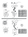
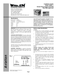
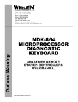
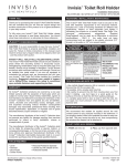
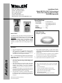
®
ENGINEERING COMPANY INC.
Route 145, Winthrop Road,
Chester, Connecticut 06412
Phone: (860) 526-9504
Fax: (860) 526-2009
Internet: www.whelen.com
Sales/Service e-mail: [email protected]
Installation Guide
Model HRCFA & SACF Self-contained
Strobe Anti-collision Light Assembly
(FAA/PMA Approved)
Specifications:
Input Voltage ................14 to 28 Volts D.C.
Current Draw ................3.2 Amps @ 14 Volts D.C.
1.6 Amps @ 28 Volts D.C.
Weight ...........................1.5 lbs.
Diameter........................ 3.7”
Overall Height............... 7.25”
A440 Mounting
Adapter (optional)
INSTALLATION...
The HRCFA & SACF self-contained strobe light assemblies are
interchangeable with Rotating Beacons on any aircraft with a 3.75
inch diameter fairing or mounting adapter. It is not necessary to
change any of the existing wiring, or circuit breakers. The light
assembly must be properly mounted to comply with FAR Part
91.205(c-2) & (c-3). When necessary (such as fuselage
installation), the Whelen model A440 mounting adapter must be
used.
MOUNTING...
1.
Remove the existing beacon.
7.
2.
Make the necessary wiring connections using the existing
wiring. Positive (+) to the WHITE wire, and Ground (-) to
the BLACK wires protruding from the light assembly. All
connections must use FAA approved techniques.
When installing the light assembly in a rudder mount location,
rudder balance must be checked with reference to the aircraft’s
service manual. The weight and balance should equal the original
rotating beacon.
8.
Check all avionics systems for interference from the installation
with reference to AC 43.13-2a, Chapter 4, paragraph 52 (b).
9.
Label all switches and breakers, install pilot warning placard.
10.
Update aircraft records and complete FAA form #337.
Aviation
Note: It is recommended to ground the unit to the buss bar
or the battery. Using the airframe as ground may produce
EMI/RFI interference.
3.
4.
5.
6.
Remove the three (3) 6-32 x 3/8” mounting screws from the
light assembly. Do not use longer screws, damage to the
unit may occur.
Flash Tube Replacement...
Insert light assembly into mounting location and attach
using screws as mentioned in step 3. There are two sets of
mounting screw locations on the unit for installation
versatility (unit may be sealed around periphery with RTV or
equivalent).
1.
When a flash tube failure occurs, remove the #6 Phillips
head screw on the clamp ring. Be careful not to lose the #6
hex nut.
2.
Remove the clamp ring.
If the A440 mounting adapter is used, attach light assembly
to adapter using screws as mentioned in step 3 (unit may be
sealed around periphery with RTV or equivalent).
3.
Lift the lens assembly & gasket off the strobe tube.
4.
Lift the strobe tube and carefully unplug the connector.
5.
Replace with new strobe tube assembly.
If light assembly is mounted in an inverted position, drill a 1/
8” diameter hole in lens as indicated on the lens label. For
the model SACF series, remove the RTV plug from the hole
in the lens.
6.
Attach all parts as required.
See parts breakdown for replacement part numbers.
©2001 Whelen Engineering Company Inc.
Form No.13611 (071801)
Page 1
*NOTE*
.156 DIA.
(5) HOLES
75º
1
2
3
4
5
6
ALIGN REFLECTORS AS SHOWN
1/8
E
IF
9
D
E
I NVE RT
FRONT
75º
7
H
OL
DR I
75º
LL
8
75º
5.00 DIA
10 11
HRCFA
PARTS
LIST
12
4.65 DIA. B.C.
2.33 DIA.
OPTIONAL MOUNTING
ADAPTER POSITIONS
13
14 15
7.01
16
+/-.03
1.75
16
19-130074-100
15
N/A
#6 INT. TOOTH LW(MS35333-71)
14
N/A
#6-32x3/8 PPHMS(MS51957-28)
13
01-0770619-00
12
01-0770044-02
A469B FLASH TUBE ASSY.
11
38-0250429-00
RFI GASKET
10
38-0230840-00
GASKET
9
N/A
8
01-0450685-00
A440 MOUNTING FLANGE (OPTIONAL)
POWER SUPPLY ASSEMBLY
#6-32 X 5/16 SS HEX NUT (MS35649-264)
CLAMP RING
7
N/A
6
68-2170504R60
LENS, A402ADS
5
68-2170504R30
LENS, A402ADW
4
68-2170504R50
LENS, A402ADR
3
68-2170504-60
LENS, A402AS
2
68-2170504-30
LENS, A402AW
1
68-2170504-50
LENS, A402AR
#6-32x1/2 PPHMS(MS51957-30)
18.00+/-.50
ITEM
PART NUMBER
DESCRIPTION
3.67 DIA
BLACK(GROUND)
WHITE(+14/28V)
1
.156 DIA.
(5) HOLES
75º
6
2
SHOWN ROTATED FOR ILLUSTRATION
OF PARTS.
75º
3
75º
5.00 DIA
FRONT
10
75º
SACF
PARTS
LIST
4
4.65 DIA. B.C.
7
8
5.50
5 9
2.97
1.75
OPTIONAL
LOCATION
3.67 DIA.
10
N/A
#6-32 x 1/2 PPHMS (MS51957-30)
9
N/A
#6 INT TOOTH L/W (MS 35333-71)
8
19-130074-100
7
01-0770619-00
6
N/A
#6-32 x 5/16 SS HEX NUT (MS35649-264)
5
N/A
#6-32 x 3/8 PPHMS (MS51957-28)
4
02-0350053-00
SA406 FLASH TUBE ASSEMBLY
3
38-0230946-00
GASKET
2
01-0450685-00
CLAMP RING
1
68-4230044-30
SA402 LENS (CLEAR)
ITEM
18.00 ±1.00
WHITE (+)
BLACK (GROUND)
Page 2
PART NUMBER
A440 MOUNTING FLANGE (OPTIONAL)
POWER SUPPLY HR-CF 14/28V
DESCRIPTION