1
VFI-KT Series User Manual
User Manual
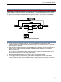
System block diagram
The UPS can be installed and operated as a single unit or it can be operated with other units of the same
type in parallel N+1 redundant mode for additional reliability, or in a parallel capacity mode for increased
output rating. To operate in parallel, units must be specified and purchased with a factory fitted parallel
kit. Figure 1 is a functional block diagram representing a single UPS. In cases where it is not possible to
meet the hold-up time with an internal battery, an external battery pack can be added.
Figure 1 Single unit block diagram
Features
■
VFI-KT units have an intelligent online sine wave
- output with power factor correction. High
frequency double-conversion and a wide input voltage range ensure continuous output for areas with
poor power supply regulation.
■
DSP technology for digital control ensures high reliability, circuit protection and self -diagnostics in the
unlikely event of a fault. Intelligent digital battery management extends battery life and ensures
optimum performance.
■
An LCD panel and LED indicators clearly display the system status and system parameters such as
input/output voltage, frequency, load, and unit temperature.
■
Network power management can be achieved by using UPS monitoring software.
■
A hot-plug input/output and maintenance bypass switch assembly ensures power to the load is
maintained if you need to service or repair a single unit. Where units are used in parallel an external
maintenance bypass switch must be used as the built in bypass switch is only rated for the current of
a single UPS.
7