1
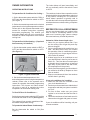
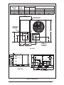
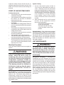
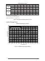
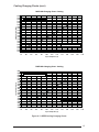
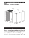
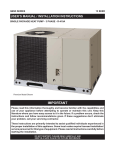
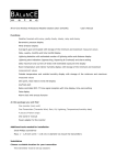
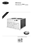
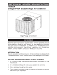
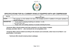
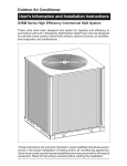
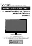
USER'S MANUAL/INSTALLATION INSTRUCTIONS
P6 Series
Single Package Convertible Air Conditioner
TM
Single Package Convertible Air Conditioner
IMPORTANT
These instructions are primarily intended to assist qualified individuals
experienced in the proper installation of heating and/or air conditioning appliances. Some local codes require licensed installation/service personnel for this
type equipment. All installations must be in accordance with these instructions
and with all applicable national and local codes and standards.
Read these instructions thoroughly before starting the installation. Follow all
precautions and warnings contained within these instructions and on the unit.
TABLE OF CONTENTS
OWNER INFORMATION ...............................................................................................................3
OPERATING INSTRUCTIONS ......................................................................................................3
GENERAL SPECIFICATIONS ......................................................................................................4
SAFETY CONSIDERATIONS .......................................................................................................4
Literature, Labels, and Tags..................................................................................................4
Pressures Within The System...............................................................................................4
INSTALLATION REQUIREMENTS ...............................................................................................4
Equipment Check .................................................................................................................4
Requirements and Codes .....................................................................................................4
Unit Dimensions ...................................................................................................................5
Unit Location.........................................................................................................................6
Air Filter Requirements .........................................................................................................6
Internal Air Filter Assembly Removal....................................................................................7
Condensate Drain.................................................................................................................7
UNIT INSTALLATION ...................................................................................................................7
Ground Level ........................................................................................................................7
Rigging and Hoisting ............................................................................................................7
Rooftop .................................................................................................................................8
AIR SUPPLY .................................................................................................................................8
Unconditioned Spaces..........................................................................................................9
Acoustical Ductwork .............................................................................................................9
Horizontal to Down Flow Conversion....................................................................................9
Clearance .............................................................................................................................9
ELECTRICAL WIRING ..................................................................................................................9
General .................................................................................................................................9
Line Voltage ..........................................................................................................................9
Blower Speed .....................................................................................................................10
Room Thermostat ...............................................................................................................10
SYSTEM CHECK ........................................................................................................................12
Pre-Start Check List ...........................................................................................................12
START-UP PROCEDURE ...........................................................................................................12
Air Circulation .....................................................................................................................12
System Cooling ..................................................................................................................12
System Heating ..................................................................................................................12
UNIT MAINTENANCE.................................................................................................................12
Refrigerant Charging ..........................................................................................................12
Routine Maintenance..........................................................................................................13
Installation / Removal of Air Filters .....................................................................................13
Package A/C Blower Curves ..............................................................................................14
Refrigerant Charging Charts .........................................................................................14-15
Wiring Diagrams ............................................................................................................16-19
2
OWNER INFORMATION
The indoor blower will start immediately, and
will run continually until the fan switch is reset
to AUTO.
OPERATING INSTRUCTIONS
To Operate Your Air Conditioner for Cooling —
1. Set the thermostat system switch to COOL or
AUTO and the thermostat fan switch to AUTO.
(See Figure 1)
2. Set the thermostat temperature to the desired
temperature level using the temperature selector.
Please refer to the separate thermostat user’s
manual for complete instructions regarding
thermostat programming. The outdoor unit
and indoor blower will both cycle on and off to
maintain the indoor temperature at the desired
cooling level.
To OperateYour Unit for Heating — (If optional
heat accessory is installed.)
1. Set the thermostat system switch to HEAT or
AUTO and the thermostat fan switch to AUTO.
(See Figure 1)
SYSTEM
MODE
FAN
SWITCH
TEMPERATURE
SENSOR
Figure 1. Typical Thermostat
2. Set the thermostat temperature to the
desired temperature level using the temperature
selector. Please refer to the separate user’s
manual for complete thermostat programming
instructions. The furnace and indoor blower
will cycle on and off to maintain the indoor
temperature at the desired heating level.
To Shut Off Your Air Conditioner —
Set the thermostat system switch to OFF and the
thermostat fan switch to AUTO. (See Figure 1)
The system will not operate, regardless of the
thermostat temperature setting.
The continuous indoor blower operation can be
obtained with the thermostat system switch set
in any position, including OFF. The continuous
indoor blower operation is typically used to
circulate the indoor air to equalize a temperature
unbalance due to a sun load, cooking, or fireplace
operation.
BEFORE YOU CALL A SERVICEMAN
Let your serviceman check your system at the
start of each air conditioning season. He will
make sure it’s working right, clean or change
filters and make any needed adjustments.
Otherwise, follow these simple rules:
1. Never run your system without filter. If you
do, the cooling coils will get dirty and may
become clogged.
2. Set your thermostat at the comfort level you
wish – and then leave it alone. Let it control
the operation of the air conditioning system.
If you get chilly, turn it up a degree at a time
until comfort is restored.
3. It takes longer for an air conditioner to cool
your dwelling than it does for your furnace to
heat it. So. . . don’t turn the unit on and expect
a dramatic drop in temperature, at least not
right away. If your home is hot and humid,
the temperature will drop slowly.
4. Check your filters regularly, to ensure there is
not extensive dirt build-up. Replace or clean
filter as needed.
5. Keep your condenser coil clean.You can hose
it down when it gets dirty.
If your air conditioner isn’t working:
1. Make sure the fuses are not blown or that
your circuit breakers are on.
2. See that your thermostat is set at the desired
temperature and that your system’s switch is
on “Cool”.
3. For free air flow, make sure your return
register is not covered and that the filter is
clean.
4. Check the condenser coil and make sure it is
clean and not clogged with grass or leaves.
If your air conditioner still isn’t working, call your
nearest contractor.
To Operate the Indoor Blower Continuously—
Set the thermostat fan switch to ON (See
Figure 1)
3
SPECIFICATIONS
Packaged Air Conditioners are designed for
outdoor rooftop or ground level slab installations.
The units are shipped ready for horizontal
duct connections and are easily converted for
downflow applications.
All models are shipped from the factory with
the following:
1. Zero clearance to combustibles.
2. Multi-speed direct-drive or fixed torque
blower.
3. High Pressure Switch.
4. Blower Speed Relay.
5. Horizontal or Downflow duct connections.
The unit dimensions are shown in Figure 2.
Optional field-installed electric heater kits
are available in 5 kw through 20 kw heating
capacities for single phase, and 9 kw through 15
kw heating capacities for three phase. A separate
installation instruction document for the electric
heaters and their application is shipped with
the heater kits. A single stage cooling 24VAC
thermostat should be used with these units. If
electric heat will be installed, a single-stage
cooling, single stage heating thermostat will
be required.
Improper installation, service,
adjustment, or maintenance may
cause explosion, fire, electrical shock
or other hazardous conditions which
may result in personal injury or
property damage. Unless otherwise
noted in these instructions, only
factory authorized kits or accessories
may be used with this product.
Noncompliance may void the unit’s
warranty.
Labels, Tags — When working with this
equipment, follow all precautions in the literature,
on tags, and on labels provided with the unit
and/or approved field installed kits. The type
of hazard and severity are described on each
label or tag.
Pressures Within The System — This
equipment contains R410-a refrigerant under
high pressure. Installation or servicing should
only be performed by qualified trained personnel
thoroughly familiar with this type equipment.
INSTALLATION REQUIREMENTS
CAUTION:
This unit uses refrigerant R-410A. DO
NOT under any circumstances use any
other refrigerant besides R-410A in
this unit. Use of another refrigerant will
damage this unit.
SAFETY CONSIDERATIONS
It is the responsibility of the installer to ensure
that the installation is made in accordance with
all applicable local and national codes.
4
WARNING:
Equipment Check — Before beginning the
installation, verify that the unit model is correct for
the job. The unit model number is printed on the
data label. All units have been securely packaged
at the point of shipment. After unpacking the unit,
carefully inspect it for apparent and concealed
damage. Claims for damage should be filed with
the carrier by the consignee.
Requirements and Codes — The installer
must comply with all local codes and regulations
which govern this type equipment. Local
codes and regulations take precedence over
any recommendations contained in these
instructions. All electrical wiring must be made
in accordance with local codes and regulations
and with the National Electric Code (ANSI/NFPA
70) or in Canada the Canadian Electric Code
Part 1 CSA C.22.1. Air Ducts must be installed
in accordance with the standards of the National
Fire Protection Association “Standards for
Installation of Air Conditioning and Ventilation
Systems” (NFPA 90A), “Standard for Installation
of Residence Type Warm Air Heating and Air
Conditioning Systems” (NFPA 90B), these
instructions and all applicable local codes.
Center of Gravity
Height (in inches)
C
with base rails
without base rails
Model No.
P6SD
Unit
Weight
A
B
X36
405
29.5
26.0
39.0
35.3
X48
415
29.5
26.5
39.0
35.3
X60
480
30.0
27.5
43.0
39.3
24 9/10
3/4" NPT Female
Drain Connector
DOWNFLOW
SUPPLY DUCT
OPENING
47 1/2
CG
13 1/2
16
16
13 1/2
B
13 3/10
12
12
23 1/2
DOWNFLOW
RETURN DUCT
OPENING
A
Top View
1.8
1.75 Ø Power Entry (Capped)
1.25 Ø Power Entry
4.0
5.0
0.88 Ø Control Wiring Entry
30.0
SUPPLY
27.2
C
CONDENSING
COIL
RETURN
13.5
23.6
16.0
8
13.5
16.0
14.7
13.45
4.00
11.75
Side View
22.75
55.8
Back View
Figure 2. Dimensions
5
72"
36"
36"
36"
0"
Figure 3. Minimum Clearances
NFPA publications are available by writing:
National Fire Protection Association
Batterymarch Park
Quincy, Maine 02269
Unit Location — This air conditioner is
designed only for outdoor installations. Choosing
the location of the unit should be based on
minimizing the length of the supply and return
ducts. Consideration should also be given to
availability of electric power, service access,
noise, and shade. Sufficient clearance for
unobstructed airflow through the outdoor
coil must be maintained in order to achieve
rated performance See Figure 3 for minimum
clearances to obstructions.
Unit Size
Internal Filter Size
R6GD-X36
P6SD-X36
P6SD-X48
(2) 16” x 25” x 1”
or
(2) 16” x 25” x 2”
Q6SD-X36
P6SD-X60
Q6SD-X48/X60, R6GD-X48/X60
(2) 18” x 25” x 1”
or
(2) 18” x 25” x 2”
Table 1. Internal Filter Size Requirements.
6
Securing
Screw
Figure 3a. Internal Filter Rack Location
Air Filter Requirements — Three phase units
“Only” are supplied from the factory with an
internal filter rack assembly. Air filters are not
supplied; a suitable air filter must be installed in
the unit or in the return air system for all units.
See Table 1 for internal filter size requirements.
When utilizing an Economizer or Fresh Air
Equipment, the factory installed filter rack
assembly must be removed prior to installation.
Refer to Table 1 for recommended filter sizes
when the factory installed filter system is not
used. Air filter pressure drop must not exceed
0.08 inches WC. Air filter(s) must be installed in
the return air ductwork ahead of the evaporator
coil of this unit. All return air to this unit must pass
4.) Install a 2 inch condensate trap in the drain
line of the same size and prime with water. When
connecting rigid drain line, hold the female fitting
with a wrench to prevent twisting. Do not overtighten! Refer to local codes and restrictions for
proper condensate disposal requirements.
UNIT INSTALLATION
Condensate Drain
Figure 4. Condensate Drain
through the filter(s) before entering this unit. (See
Routine Maintenance for Installation/Removal
of air filters).
Removal of Internal Filter Rack — First remove
the Return Air Panel from the unit. Remove the
height adjustment screw from the inside of the
rack, and the (1) screw securing the assembly
to the coil located on the left leg of the rack. The
assembly can easily be collapsed and removed
from the unit. See Figure 3a for filter rack securing
screw locations.
Condensate Drain — Condensate is removed
from the unit through the 3/4" female pipe fitting
located on the front side of the unit. (See Figure
Ground Level — When installing the unit at
ground level, provide a concrete mounting pad
separate from the building foundation. The
pad must be level to insure proper condensate
disposal and strong enough to support the unit’s
weight. Refer to Figure 2 . Make sure the slab
is a minimum of 2" above the grade and in an
area that drains well. (Figure 5)
CAUTION:
All panels must be securely in place
when rigging and hoisting.
Rigging and Hoisting — The unit should be lifted
using slings and spreader bars. The spreader
bars are necessary to prevent damaging the top
of the unit’s cabinet. Make sure that the lifting
equipment is adequate for the load. Refer to
Figure 2 for unit weights. Keep the unit in an
upright position at all times. For rooftop installations, remove and discard the two supports
attached beneath the unit.
TM
2"
Figure 5. Ground Level Installation
7
Figure 6. Roof Top Installation
AIR DUCTS
WARNING:
To avoid the risk of property damage
or personal injury; it is the rigger’s
responsibility to insure that whatever
means are used to hoist the unit are
safe and adequate.
The rigging must be located outside the unit’s
center of gravity. Refer to Figure 2 for center
of gravity location.
Rooftop — For rooftop installations use the
appropriate accessory roof curb and follow all
instructions included with it. Make sure the two
supports beneath the unit have been removed.
Locate the unit according to local building codes
and ordinances. The curb must be level to insure
proper condensate drainage. (See Figure 6)
The roof must be capable of handling the weight
of the unit. (See Figure 2) for unit weights.
Reinforce the roof if required.
8
This unit is designed only for use with a supply
and return duct. Air ducts should be installed in
accordance with the standards of the National
Fire Protection Association “Standard for
Installation of Air Conditioning Systems” (NFPA
90A), “Standard for Installation of Residence Type
Warm Air Heating and Air Conditioning Systems”
(NFPA 90B), and all applicable local codes.
Design the duct work according to methods
described by the National Warm Air Heating
and Air Conditioning Association (ACCA). The
ducts must be properly sized not to exceed .2"
w.c. pressure drop at 400 scfm per nominal ton
of cooling capacity.
Duct work should be attached directly to the unit
flanges for horizontal applications. On roof curb
installations the ducts must be attached to the
curb hangers, not the unit.
Unconditioned Spaces — All duct work
passing through unconditioned space must be
properly insulated to minimize duct losses and
prevent condensation. Use insulation with an
outer vapor barrier. Refer to local codes for
insulation material requirements.
Acoustical Duct Work — Certain installations
may require the use of acoustical lining inside
the supply duct work. Acoustical insulation must
be in accordance with the current revision of the
Sheet Metal and Air Conditioning Contractors
National Association (SMACNA) application
standard for duct liners. Duct lining must be UL
classified batts or blankets with a fire hazard
classification of FHC-25/50 or less. Fiber duct
work may be used in place of internal duct liners
if the fiber duct work is in accordance with the
current revision of the SMACNA construction
standard on fibrous glass ducts. Fibrous duct
work and internal acoustical lining must be NFPA
Class 1 air ducts when tested per UL Standard
181 for Class 1 ducts.
Horizontal to Down flow Conversion — The unit
is shipped ready for horizontal duct connections.
If down flow ducts are required, the unit must be
converted following the steps below for both the
supply and return ducts.
1) Locate the duct cap inside the duct openings
and remove the screw holding it in place.
2) Lift the cap out of the unit. (The cap can be
pushed up from the bottom by reaching
through the fork slot).
3) Cover the horizontal duct opening with the
cap. The insulation will be on the indoor
side.
4) Fasten the cover with screws and seal to
prevent air leakage.
Clearance — This unit is approved for 6 inch
clearance.
ELECTRICAL WIRING
General — Electrical power wiring must be
made in accordance with all applicable local
codes and ordinances, and with the current
revision of the National Electric Code NFPA 70
or in Canada CSA C.22.1 - Canadian Electrical
1
RED
2
3
BLUE
4
BLACK
5
6
WHITE
Code Part 1. If any of the original wire as supplied
with the unit must be replaced, it must be
replaced with material of the same gauge and
temperature rating.
WARNING:
To avoid risk of electrical shock,
personal injury, or death, disconnect
all electrical power to the unit before
performing any maintenance or service.
The unit may have more than one electrical supply.
Line Voltage — Before proceeding with the
electrical connections, make certain that the
voltage, frequency, and phase of the supply
source are the same as those specified on the unit
rating plate. Also verify that the service provided
by the utility is sufficient to handle the additional
load imposed by this equipment.
See the unit wiring label for proper high and low
voltage wiring. Make all electrical connections
in accordance with all applicable codes and
ordinances.
Use a separate branch electrical circuit for this
unit. A means of electrical disconnect must be
located within sight of and readily accessibility
to the unit. Internally mounted circuit breakers
are available as field installed options. These
circuit breakers can be used as an electrical
disconnect.
The unit is shipped from the factory wired for 240
volt transformer operation. For 208 volt operation,
remove the lead from the transformer terminal
marked 240V and connect it to the terminal
marked 208V. For maximum ampacity and over
current protection, see the unit rating plate.
Provide power supply (or supplies) for the unit in
accordance with the unit wiring diagram, and the
PIN NUMBER
WIRE COLOR
MOTOR SPEED
1
RED
LOW
3
BLUE
MEDIUM
4
BLACK
HIGH
5
N/A
N/A
6
WHITE
COMMON
2
Figure 7. Motor Lead Connector - Standard Motor
9
unit rating plate. Connect the line-voltage leads
to the corresponding terminals on the contactor
(or the circuit breaker when the field installed
circuit breaker kits are used) inside the control
compartment. Use only copper wire for the line
voltage power supply to this unit. Use proper code
agency listed conduit and a conduit connector
for connecting the supply wires to the unit and
for obtaining proper grounding. Grounding may
also be accomplished by using the grounding
lug provided in the control box.
WARNING:
The unit cabinet must have an
uninterrupted or unbroken electrical
ground to minimize personal injury if
an electrical fault should occur. This
ground may consist of electrical wire
or approved conduit when installed in
accordance with existing national or
local codes.
Blower Speed — The blower speed is preset
at the factory for operation at the same speed
for heating and cooling. For optimum system
performance and comfort, it may be necessary
to change the factory set speed. See table 1 for
factory settings. To change the blower speed:
If Standard Motor:
1. Disconnect all electrical power to the
unit and remove the service panel.
2. Remove the motor lead from terminal #4 of
the blower relay. Cut the wire tie holding the
motor lead bundle. The motor leads are
color coded as shown in Figure 7.
3. If the desired heating blower speed is different
than the cooling speed, remove and discard
the jumper wire between terminals #6 and
#4. on the blower relay. Place the desired
heating blower speed lead on terminal #6 and
the desired cooling blower speed lead on
terminal #4 of the blower relay. Use another
wire tie (field supplied) to bundle the remaining
motor leads.
If Fixed Torque Motor:
1. Disconnect all electrical power to the unit
and remove the blower panel.
2. Locate the orange and red wires terminated
to the blower motor. The orange wire controls
cooling operation while the red wire controls
heating operation.
3. Verify the required speed from the airflow
data found in table 1. Place appropriate wire
10
on the appropriate motor speed tap for the
required airflow point.
Check all factory wiring per the unit wiring
diagram and inspect the factory wiring connections to be sure none loosened during shipping
or installation.
CAUTION:
To avoid personal injury or property
damage, make certain that the motor
leads cannot come into contact with
any uninsulated metal components
of the unit.
Low Voltage Connections
Room Thermostat — Several options are
available for a room thermostat depending on
the accessories installed with the unit. Select a
thermostat which operates in conjunction with
the installed accessories. The thermostat should
be mounted about five feet above the ground on
an inside wall. The thermostat should be kept
away from drafts, slamming doors, lamps, direct
sunlight, or in line with the supply air flow.
To install the thermostat:
1. Position the sub base on an inside wall and
mark the mounting holes and thermostat
cable openings.
2. Cut out the cable opening and route the
thermostat cable from the unit’s low voltage
compartment to the thermostat location.
The thermostat cable is supplied by the
installer.
3. Connect the cable leads to the sub base or
thermostat terminals and to the unit’s low
voltage pigtails as shown in Figure 8. A
system wiring diagram is also provided on
the inside of the control panel cover.
4. Secure sub base or thermostat to the wall using screws provided with the thermostat.
5. If sub base is used, install the correct
thermostat housing to sub base.
6. Refer to thermostat instruction sheet for
complete detailed mounting information.
Field Installed Electric Heat — This
Packaged Air Conditioner is designed to allow
optional electric heat to be field installed as required by the building’s particular heating load.
The options available for each unit are shown in
the heater kit installation instructions.
Brown 1
Orange 2
3
4
5
6
7
8
9
FROM
BLOWER RELAY
Green
W
ACCESSORY
HEAT PLUG
G
C
ECONOMIZER
PLUG
1
Gray 2
3
Yellow 4
Blue 5
6
7
8
9
FROM
CONTACTOR
Y
R
INDOOR
THERMOSTAT
SUB-BASE
(Optional,
Check
Thermostat
Instructions)
Black
FROM
TRANSFORMER
Red
Typical Wiring (Field Supplied) for 1-Stage Cool, 1-Stage Heat
Optional
Outdoor Thermostat
(Field Supplied)
Brown 1
Orange 2
3
4
5
6
7
8
9
W2
W1
Green
G
ACCESSORY
HEAT PLUG
C
Y2
ECONOMIZER
PLUG
1
Gray 2
3
Yellow 4
Blue 5
6
7
8
9
FROM
BLOWER RELAY
FROM
CONTACTOR
Y1
Black
R
INDOOR
THERMOSTAT
SUB-BASE
(Optional, Check
Thermostat Instructions)
FROM
TRANSFORMER
Red
Typical Wiring (Field Supplied) for 2-Stage Cool, 2-Stage Heat with an
Optional Outdoor Thermostat
Figure 8. Typical Air Conditioner Thermostat Connections
11
Install the heater kits as directed by the installation instructions that come as part of the
heater kit. Follow all cautions and warnings as
directed.
System Cooling
1.
START UP AND SYSTEM CHECK
Pre-Start Check List
•
Verify that the unit is level to allow proper
condensate drainage.
•
Verify that there is free airflow to and from
the outdoor coil and that all clearance
requirements are met.
•
Verify that the duct work is sealed to prevent
air leakage.
•
Verify that the line voltage power leads are
securely connected and the unit is properly
grounded.
•
Verify that the low voltage wires are securely
connected to the correct leads on the low
voltage terminal strip.
•
Verify that all exterior panels are replaced
and securely fastened.
•
Verify that the outdoor fan turns freely.
•
Verify that the power supply branch circuit
overcurrent protection is sized properly.
•
Verify that the thermostat is wired correctly.
The thermostat function switch should be
set to "Off" and the thermostat fan switch
should be set to "Auto'.
Start-Up Procedure
Close all electrical disconnects to energize the
system.
WARNING:
If the unit is equipped with a crankcase
heater, allow 24 hours prior to
continuing the start up procedures
to allow for heating of the refrigerant
compressor crankcase. Failure to
comply may result in damage and could
cause premature failure of the system.
This warning should be followed at
initial start up and any time the power
has been removed for 12 hours or
longer.
Air Circulation — Leave the thermostat system
switch set to “Off” and set the thermostat fan
switch to “On". The blower motor should run
continuously. Check for air delivery at the
register(s). Ensure that there are no obstructions
at the registers or in the duct work. Set thermostat
fan switch to “Auto.”
12
2.
Set the thermostat system switch to
“Cool” and the thermostat fan switch to
“Auto". Gradually lower the thermostat
temperature switch below room temperature
and observe that the blower, compressor,
and fan energize. Check that air cooler than
room temperature is being discharged
at the register. Listen for any unusual
noises. Locate the source and correct as
needed.
After allowing the unit to run for several
minutes, set the temperature selector
above room temperature.
- The fan and compressor cycles
off with the thermostat.
- The blower should also stop
unless fan switch is set to “ON”
position.
System Heating — If the unit has been equipped
with optional electric heater kits, set the system
thermostat switch to HEAT and set the thermostat
fan switch to AUTO. Verify that the compressor
and outdoor fan are not energized but that the
blower and heaters are. Check for warm air at
the supply registers.
UNIT MAINTENANCE
WARNING:
To avoid risk of electrical shock,
personal injury, or death, disconnect
all electrical power to the unit before
performing any maintenance or service.
The unit may have more than one electrical supply.
Refrigerant Charging — Packaged air
conditioners are fully charged with R-410A
refrigerant at the factory. The system refrigerant
charge can be checked and adjusted through
the service ports provided on the front panel.
Use only gauge lines which have a “Schrader”
depression device present to actuate the valve.
Draw a vacuum on gauge lines to remove air
before attaching them to the service ports on
the unit. Refrigerant charging must be done
by qualified personnel familiar with safe and
environmentally responsible refrigerant handling
procedures.
WARNING:
Single Packaged Air Conditioners are
shipped fully charged with R-410A
refrigerantand ready for installation.
When a system is installed according
to these instructions, no refrigerant
charging is required. If repairs make
it necessary for evacuation and
charging, it should only be done by
qualified, trained personnel thoroughly
familiar with this equipment. Some local
codes require licensed installation/
service personnel to service this type
of equipment. Under no circumstances
should the owner attempt to install
and/or service this equipment. Failure
to comply with this warning could
result in property damage, personal
injury, or death.
CAUTION:
Use care when removing parts from
this unit. Personal injury can result
from sharp metal edges present
in all equipment of sheet metal
construction.
Routine Maintenance — Proper maintenance
is important to achieve optimum performance
from the air conditioner. The ability to properly
perform maintenance on this equipment requires
certain mechanical skills and tools. If you do not
possess these skills, contact your dealer for
maintenance. Consult your local dealer about
the availability of maintenance contracts. At a
minimum, routine maintenance should include
the following:
1.
2.
3.
Inspect and clean or replace air filters at
the beginning of each heating and cooling
season, or more frequently if required.
Inspect the condensate drain and outdoor
coil at the beginning of each cooling season.
Remove any debris. Clean the outdoor
coil and louvers as necessary using a
mild detergent and water. Rinse thoroughly
with water.
Inspect the electrical connections
for tightness at the beginning of each
heating and cooling season. Service as
necessary.
INSTALLING FILTERS IN THE FACTORY INSTALLED FILTER RACK (3
PHASE ONLY)
1. Remove access panel screws from return air
panel. (You may want to loosen the unit’s Top
Panel screws that are located near the top
edge of the access panel. The access panel
was designed to be captured underneath
the Top Panel.)
2. To install media, slide filter between guide
channels of filter rack. The first filter will
easily drop into place. (Check to insure that
the bottom of filter is within the channels of
the rack.) Insert the second media in the
same manner as the first. (Again, check
to insure that the media is captured by the
channels of the filter rack.
3. Replace access cover by sliding the top
edge of panel under the lip of the unit’s Top
Panel. Secure Access Panel by replacing
the screws.
REMOVAL OF FILTERS FROM FACTORY
INSTALLED FILTER RACK (3 PHASE ONLY)
1. Remove access panel screws from return air
panel. (You may want to loosen the unit’s Top
Panel screws that are located near the top
edge of the access panel. The access panel
was designed to be captured underneath
the Top Panel.)
2. To remove upper media, gently pull filter
through the Access Panel opening.
3. To remove lower media, lift media to top of
Filter Rack and remove in the same manner
as described in step two.
4. Replace old filter with new media per the
Insertion Instruction detailed above.
CAUTION:
The unit should never be operated
without a filter in the return air system.
Replace disposable filters with the
same type and size.
13
P6 Series Blower Curves
Model Number
P6SDHigh
X36
Medium
* Low
High
X48
Medium
* Low
Tap T1
* * Tap T2
X60
* Tap T3
Tap T4
Tap T5
0.1
1610
1367
1153
2361
2026
1584
1515
1580
1740
1960
2090
External Static Pressure Drop - inches water column
0.2
0.3
0.4
0.5
0.6
0.7
1562
1504
1442
1365
1295
1214
1320
1271
1205
1138
1065
968
1102
1043
990
912
831
731
2278
2218
2141
2066
1976
1870
1982
1935
1889
1822
1744
1660
1568
1532
1489
1445
1387
1322
1450
1380
1350
1280
1250
1200
1520
1460
1400
1300
1280
1260
1690
1650
1600
1360
1500
1460
1910
1840
1820
1540
1740
1700
2050
2010
1975
1780
1900
1850
0.8
1109
845
618
1758
1554
1236
1160
1230
1390
1600
1790
* Denotes factory set cooling speed
** Denotes factory set electric heating speed
NOTE: Airflow performance is with a dry coil
Table 1. Packaged Air Conditioner Blower Curves
Cooling Charging Charts
Liquid Pressure (psig)
P6SD-X36 Charging Chart - Cooling
600
580
560
540
520
500
480
460
440
420
400
380
360
340
320
300
280
260
240
220
200
Remove refrigerant when above curve
Add refrigerant when below curve
75
80
85
90
95
100
105
110
115
120
Liquid Temperature (F)
Figure 9: 13 SEER Cooling Charging Charts
14
125
130
135
Cooling Charging Charts (cont.)
Liquid Pressure (psig)
P6SD-X48 Charging Chart - Cooling
600
580
560
540
520
500
480
460
440
420
400
380
360
340
320
300
280
260
240
220
200
Remove refrigerant when above curve
Add refrigerant when below curve
75
80
85
90
95
100
105
110
115
120
125
130
135
Liquid Temperature (F)
Liquid Pressure (psig)
P6SD-X60 Charging Chart - Cooling
600
580
560
540
520
500
480
460
440
420
400
380
360
340
320
300
280
260
240
220
200
Remove refrigerant when above curve
Add refrigerant when below curve
75
80
85
90
95
100
105
110
115
120
125
130
135
Liquid Temperature (F)
Figure 9. 13 SEER Cooling Charging Charts
15
T1
Figure 10. Wiring Diagram-Standard Motor, Three Phase
FIELD WIRING
LOW VOLTAGE
HIGH VOLTAGE
LEGEND:
COMPRESSOR
T2
BLACK
COMPRESSOR
CONTACTOR
T2
T3
T3
BLACK
L2
T1
L1
BLUE
OUTDOOR
FAN MOTOR
C
BLACK
BLACK
WHITE
WHITE
RED
S
R
BLACK
PRESSURE
SWITCH
ORANGE
CCH
YELLOW
BK
BLACK
YELLOW
CAPACITOR
BLACK
L3
TO 208/230 VAC
POWER SUPPLY
BLACK
YELLOW
1
2
3
4
5
6
7
8
9
1
2
3
4
5
6
7
8
9
PLUG
A
BLACK
RED
YELLOW
W2
R
208/230 Volt
RED
3 AMP
FUSE
24V
240V 208V
BLUE
ORANGE
WHITE
Y
COM
4
6
3
G C
BLOWER
RELAY
2
5
1
GREY
TRANSFORMER
RED
RED
BROWN
ORANGE
NOTES:
1. Disconnect all power before servicing.
2. For supply connections use copper conductors only.
3. Not suitable on systems that exceed 150 V to ground.
4. If any of the original wire as supplied with the furnace must be
replaced, it must be replaced with wiring material having a
temprature rating of at least 105°C.
5. For supply wire ampacities and overcurrent protection, see unit
rating plate.
BLACK
WIRING DIAGRAM
GREEN
16
Convertable Packaged Air Conditioner
BLACK
7107630
RED
GREEN
WHITE
RED
ORANGE
BLUE
BLACK
YELLOW
BLUE
60H z
9
8
7
6
5
4
3
2
1
9
8
7
6
5
4
3
2
1
1
2
3
4
5
6
RED
RED
1
2
3
4
5
6
9
8
7
6
5
4
3
2
1
M
H
L
BLOWER
MOTOR
9
8
7
6
5 YELLOW
4
3
2
1
BROWN
WHITE
BLUE
BLACK
RED
ORANGE
BLUE
YELLOW
BLACK
GREY
GREEN
RED
RED
TO DISCHARGE
AIR SENSOR
C
1. Couper le courant avant de faire letretien.
2. Employez uniquement des conducteurs en cuivre.
3. Ne convient pas aux installations de plus de
150 V la terre.
Three Phase
FIELD WIRING
LOW VOLTAGE
HIGH VOLTAGE
BLUE
WHITE
RED
S
C
OUTDOOR
FAN MOTOR
HEATER
PLUG
1
1
2
2
3
3
4
4
5
5
6
6
7
7
8
8
9
9
BLACK
RED
BROWN
ORANGE
WHITE
BLACK
DEFROST BOARD OPERATION:
1 CLOSES DURING DEFROST. RATNG: 1 A MAXIMUM
2 OPENS DURING DEFROST RATING: 2 HP AT 230 VAC MAXIMUM
3 CLOSED WHEN “Y” IS ENERGIZED. OPEN WHEN “Y” IS DEENERGIZED.
PROVIDES “OFF” DELAY TIME OF 5 MIN WHEN “Y” IS DEENERGIZED.
4 WIITH DFT CLOSED AND “Y” ENERGIZED, COMPRESSOR RUN TIME IS ACCUMLATED.
OPENING OF DFT DURING DEFROST OR INTERVAL PERIOD RESETS THE INTERVAL TO 0.
CAPACITOR
R
BLACK
BLACK
RED
DF1 DF2
LEGEND:
3 PHASE
COMPRESSOR
ORANGE
BK
CCH
BLUE
BROWN
BROWN
E
T3
T1
L1
BLACK
BLACK
DEFROST
SENSOR
208/230 Volt
Low
Voltage
Terminals DFT
T2
T1
T2
L2
T3
L3
BLACK
BLACK
WHITE
BLACK
R
WHITE
TO 208/230 VAC
POWER SUPPLY
NOTES:
1. Disconnect all power before servicing.
2. For supply connections use copper conductors only.
3. Not suitable on systems that exceed 150V to ground.
4. If any of the original wire as supplied with the furnace
must be replaced, it must be replaced with wiring
material having a temperature rating of at least 105°C.
5. For supply wire ampcities overcurrent protection, see
unit rating plate.
Convertible Packaged Heat Pump
W2
YELLOW
24V
208V
COM
BLOWER
RELAY
C
RED
ORANGE
NO
RED
RED
BLOWER
MOTOR
G
N
L
C
WHITE
T1
T5
T3
T4
T2
BLACK
GREEN
GREEN
ECONOMIZER
PLUG
9 9
8 8
7 7
6 6
5 5 YELLOW
4 4
3 3
2 2
1 1
TO DISCHARGE
AIR SENSOR
ECONOMIZER
PLUG
RED
9 9
RED
8 8
WHITE
7 7
WHITE
ORANGE
YELLOW
6 6
BLUE
BLUE
5 5
4 4
YELLOW
YELLOW
3 3
BLACK
BLACK
2 2
GREY
GREY
GREEN
1 1
GREEN
GREEN
NC
Three Phase 60Hz
1. Couper le courant avant de faire letretien.
2. Employez uniquement des conducteurs en cuivre.
3. Ne convient pas aux installations de plus de 150 V
a la terre.
REVERSING
VALVE SOLENOID
NOTE: See Installation
Instructions for wiring,
application, and
Information concerning
accessory Heat Kits and
other options.
BLUE
YELLOW
240V
TRANSFORMER
RED
TO INDOOR
THERMOSTAT
G B
HIGH PRESSURE
SWITCH
T1
T2
C
Y
O
3 AMP
FUSE
WIRING DIAGRAM
BLACK
C
Y
O
W2
R
E
RED
T2
DFT
TEST
7107640
Figure 11. Wiring Diagram-Fixed Torque Motor, Three Phase
17
Figure 12. Wiring Diagram-Standard Motor, Single Phase
FIELD WIRING
LOW VOLTAGE
HIGH VOLTAGE
LEGEND:
COPMPRESSOR
C
R
BLACK
S
CCH
RED
(IF EQUIPPED)
WHITE
T2 T1
L2 L1
TO 208/230 VAC
POWER SUPPLY
HIGH
PRESSURE
SWITCH
BLUE
OUTDOOR
FAN MOTOR
R
COMPRESSOR
CONTACTOR
C
YELLOW
YELLOW
S
RED
WHITE
BLACK
BLACK
BLACK
NOTE: ONLY REQUIRED IF
NO LOW PRESSURE SWITCH
YELLOW
ORANGE
BLACK
YELLOW
DUAL
CAPACITOR
YELLOW
1
2
3
4
5
6
7
8
9
1
2
3
4
5
6
7
8
9
HEATER
PLUG
RED
YELLOW
ORANGE
LOW PRESSURE
SWITCH
(ON SELECT
MODELS ONLY)
W2
ORANGE
BROWN
208/230 Volt
208V
24V
3 AMP
FUSE
WHITE
ORANGE
BLUE
R
RED
RED
240V
OW
RED
LL
YELLOW
COM
ORANGE
2
5
1
Y GC
4
6
3
WHITE
RED
GRAY
GREEN
BLACK
YELLOW
BLUE
4. If any of the original wire as supplied with the furnace must be replaced, it must
be replaced with wiring material having a temperature rating of at least 105°C.
5. For supply wire ampacities and overcurrent protection, see unit rating plate.
Convertible Packaged Air Conditioner
BLACK
NOTES:
1. Disconnect all power before servicing.
2. For supply connections use copper conductors only.
3. Not suitable on systems that exceed 150V to ground.
GREEN
18
YE
7107830
BLUE
BLACK
RED
9
8
7
6
5
4
3
2
1
9
8
7
6
5
4
3
2
1
RED
RED
1
2
3
4
5
6
BLOWER
PLUG
1
2
3
4
5
6
WHITE
BLACK
BLUE
RED
BLUE
YELLOW
BLACK
GRAY
GREEN
ORANGE
RED
RED
M
BROWN
H
ECONOMIZER PLUG
ECONOMIZER JUMPER
HARNESS ASSY
8-WIRE
TO DISCHARGE
AIR SENSOR
L
9
8
7
6
5
4
3
2
1
YELLOW
BLOWER
MOTOR
9
8
7
6
5
4
3
2
1
C
1. Couper le courant avant de faire letretien.
2. Employez uniquement des conducteurs en cuivre.
3. Ne convient pas aux installations de plus de 150V
a la terre.
Single Phase / 60Hz
S
R
FIELD WIRING
LOW VOLTAGE
HIGH VOLTAGE
LEGEND:
COMPRESSOR
C
BLACK
CCH
T1
L1
BLACK
YELLOW
WHITE
WHITE
DUAL
CAPACITOR
T2
L2
TO 208/230 VAC
POWER SUPPLY
S
BLUE
R
RED
OUTDOOR
FAN MOTOR
C
ORANGE
RED
YELLOW
HIGH
PRESSURE
SWITCH
YELLOW
YELLOW
BLACK
RED
WHITE
BLACK
1
2
3
4
5
6
7
8
9
1
2
3
4
5
6
7
8
9
HEATER
PLUG
LOW
PRESSURE
SWITCH
(ON SELECT
MODELS ONLY)
ORANGE
BROWN
YELLOW
ORANGE
NOTE: ONLY REQUIRED IF
NO LOW PRESSURE SWITCH
BLACK
208/230 Volt
W2
24V
3 AMP
FUSE
208V
RED
RED
R
COM
ORANGE
Y GC
RED
BLACK
5
1
BLUE
WHITE
6
3
2
4
BLOWER
RELAY
GREEN
GREEN
GRAY
YELLOW
BLACK
BLUE
4. If any of the original wire as supplied with the furnace must be replaced, it must
be replaced with wiring material having a temperature rating of at least 105°C.
5. For supply wire ampacities and overcurrent protection, see unit rating plate.
Convertible Packaged Air Conditioner
GREEN
NOTES:
1. Disconnect all power before servicing.
2. For supply connections use copper conductors only.
3. Not suitable on systems that exceed 150V to ground.
RED
OW
YELLOW
LL
240V
YE
7107840
Figure 13. Wiring Diagram-Fixed Torque Motor, Single Phase
19
9
8
7
6
5
4
3
2
1
9
8
7
6
5
4
3
2
1
TO DISCHARGE
AIR SENSOR
BLOWER
MOTOR
GN/YE STRIPE
9
8
7
6
5
4
3
2
1
NOTE: FOR BLOWER MOTOR WIRING
SEE #XL0132
ORANGE
BLACK
RED
GRAY
GREEN
YELLOW
BLACK
BLUE
ORANGE
RED
RED
ECONOMIZER PLUG
ECONOMIZER JUMPER
HARNESS ASSY
8-WIRE
RED
RED
N
L
C
G
9
8
7
6
5
4
3
2
1
T2
T3
T4
T5
T1
YELLOW
1. Couper le courant avant de faire letretien.
2. Employez uniquement des conducteurs en cuivre.
3. Ne convient pas aux installations de plus de 150V
a la terre.
Single Phase / 60Hz
INSTALLER
PLEASE LEAVE THESE
INSTALLATION INSTRUCTIONS
WITH THE HOMEOWNER.
¢7089339¤
O'Fallon, MO
7089330
7089330
Specifications and illustrations
subject to change without notice and
without incurring obligations. (10/08)