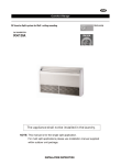
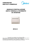
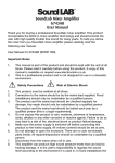
1
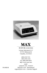
8000BTU WALL MOUNTED AIR
CONDTIONER
COOLING & HEATING
Model EH0530 (PMINISW8W)
(Refrigeration R407C)
PLEASE READ THIS INSTRUCTION MANUAL
BEFORE OPERATING AND KEEP
SAFE FOR FUTURE REFERENCE
CONTENT
Title
Page
A. Specification
3
B. Before use
4
C. Important safety instructions
D. BS plug wiring / Schuko to UK converter plug (Optional)
5, 6
7
E. Product description
8, 9
F. Wall mounting installation instructions
9-13
G. Operating instructions
14-17
H. Operation using remote controller
18-19
I. Extra air flow
20
J. Circuit diagram
20
K. Maintenance
21
L. Trouble shooting
22
M. Service & warranty
23
Page 2
A. SPECIFICATION
Model
Capacity(W)
Power (W)
EH0530 (PMINISW8W)
Cooling Capacity
2300
Heating Capacity
2400
Cooling
920
Heating
960
Dehumidifying Capacity (L/day)
25
Air Volume (m3/h)
320
Power Supply
220-240V ~ /50Hz
Noise Level (dB)
<50
Refrigerant (g)
R407C / 400g
Net Weight(KG)
32
(not includes accessories)
Dimension
465*765*235
465*765*235
(H*W*D)
536*930*315
536*930*315
* Use Type V5 remote controller only
Notes:
1. Cooling capacity is measured at ambient temperature Dry-bulb 27OC,Wet-bulb
19OC(Indoor and outdoor, the same).
Heating capacity is measured at ambient temperature Dry-bulb 20OC, Wet-bulb 15
O
C (Indoor and outdoor, the same).
Page 3
B. BEFORE USE
z
z
z
z
z
z
z
z
Transport & store the unit in an upright position only. Leave it in an upright
position for at least 3 hours before first use.
DO NOT dispose of any packaging until the installation of the air
conditioner is completed.
After having removed the packing, check that all the content is intact and
complete. (See list of accessories). In the event of missing parts, contact
your retailer.
This air conditioner has been designed to cool or heat the air of a room
and should only used for the purpose.
The manufacturer cannot be held liable for damage caused to property or
injury to persons or animals due to incorrect installation, regulation and
maintenance or improper use.
This air conditioner contains R407C refrigerant: at the end of its life, the
disposal of this air conditioner must be in accordance with the strict
regulation governing the recycling of this product, please operate with
caution during the disposal. Please contact your local authority for
regulatory advice.
DO NOT switch on before having totally assembled the air conditioner and
before installing in its correct operating position.
This unit builds with self-diagnostic function. Approximate 1 minute delay
in initial power connection.
Page 4
C. IMPORTANT SAFETY INSTRUCTIONS
z
z
z
z
z
z
z
z
z
z
z
z
z
z
z
z
z
z
z
z
z
z
Always place the unit on an even, level surface.
An opening in a window (in portable version only) or wall is required to
accommodate the exhaust hose to expel the hot air.
Ensure the unit is connected to an earthed power supply of the correct
rating. (Refer to the rating label located at the back of the unit).
The unit will cool when the room temperature is between 18°C~32°C
depending on the thermostat setting.
DO NOT tilt the unit.
DO NOT cover or obstruct the appliance’s inlet and outlet grilles.
Your air conditioner has been designed to be used only in the home, office
and similar conditions and should not be used for any other purpose.
This unit is for indoor use only.
Never unplug the air conditioner while it is working, this could damage the
electronic circuits.
DO NOT use the appliance in a wet room, such as a bathroom or laundry
room to avoid the risk of electrical shocks.
DO NOT bend or crush the warm air exhaust hose. (in portable version
only)
DO NOT sit or place articles on the appliance.
DO NOT use the appliance with wet or damp hands.
DO NOT let chemical substances come into contact with the appliance.
DO NOT use the appliance in the presence of flammable substances or
vapours such as alcohol, insecticides, petrol, etc.
DO NOT use the plug to start and stop the appliance. ALWAYS use the
intended control panel to start and stop the unit.
ALWAYS turn off the appliance when it is not in use and remove the mains
plug from the socket outlet.
ALWAYS turn the unit off and remove the mains plug before cleaning,
carrying out maintenance or moving location.
Do not pull the electrical cable or place it near a source of heat: always
unroll it completely to avoid dangerous overheating. If the power cord
becomes damaged, the service agent or a similarly qualified person must
replace it, in order to avoid a hazard.
The filter must be used with the product at all times, when removing it for
clearing always turn the unit off and unplug the mains plug from the
socket.
Do not operate the unit with a damaged power cord or plug, after it
malfunctions, has been dropped or damaged. If the power cord is
damaged it must be replaced by the manufacturer or a qualified service
engineer to avoid a hazard.
This appliance is not intended for use by persons (including children) with
reduced physical, sensory or mental capabilities, or lack of experience and
knowledge, unless they have been given supervision or instruction
concerning use of the appliance by a person responsible for their safety.
Page 5
Energy Saving Tips
z
Blocking of the filter reduces the efficiency of the air and increases its
power consumption by up to 6%.
z
Avoid opening doors frequently.
z
Each person present in a room provides between 100 Watts and 150
Watts of heat. Consequently, the more people there are in a room, the less
effective the unit will be in cooling.
z
To ensure the optimal efficiency of the unit, we advise you to keep doors
and windows closed, and to take into account the surface of the walls and
windows exposed to the sun.
z
Avoid the use of adapter plugs, multiple sockets and /or extension leads. If
their use is necessary, ensure they conform to current safety standards.
z
Before starting the appliance, check that it is correctly earthed, according
the legislation in force in the country concerned.
READ AND SAVE THESE INSTRUCTIONS
PLEASE NOTE:
RECEIVING THE GOODS
z
z
z
The air-conditioner is delivered in protective packaging and is
accompanied by an instruction manual.
This manual is an integral part of the air-conditioner and should therefore
be carefully read and preserved.
When the unit is unpacked, please check that the equipment and the
accessory pack are complete and undamaged.
HANDLING
z
z
z
z
Be fully aware of the weight of the unit before attempting to lift it. Take all
necessary precautions to avoid damaging the product or causing personal
injury.
It is advisable to remove the packing only when the air conditioner has
been located in the point of installation.
Carefully remove the adhesive strips positioned on the air-conditioner.
Packaging components must be disposed correctly and not left within
reach of children, since they are a potential source of danger.
Page 6
D. BS PLUG WIRING
Wiring Instructions: Should it be necessary to change the plug please note the
wires in the mains lead are colored in accordance with the following code:
BLUE - NEUTRAL
BROWN - LIVE
GREEN AND YELLOW - EARTH
As the colors of the wires in the mains lead of this appliance may not
correspond with the colored markings identifying the terminals in your plug,
proceed as follows:
1. The BLUE wire is the NEUTRAL and must be connected to the terminal,
which is marked with the letter N or colored BLACK.
2. The BROWN wire is the LIVE and must be connected to the terminal, which
is marked with the letter L or colored RED.
3. The GREEN/YELLOW is the EARTH
and must be connected to the terminal
which is marked with the letter E or
or colored GREEN OR
GREEN/YELLOW.
4. Always ensure that the cord grip is
positioned and fastened correctly.
If a 13A (BS 1363) fused plug is used it
must be fitted with a 13A fuse. If in doubt
consult a qualified electrician.
Wiring for a 13 Amp Plug (BS1363)
Please note. The Earth Terminal is marked with the letter E or Earth Symbol
Optional feature of Schuko to UK converter plug
This Schuko to UK converter plug may used in this product. Refer to UK plug
wiring instruction section for regular UK plug wiring.
Page 7
E. PRODUCT DESCRIPTION
1.
Air outlet
8.
2.
LED display
9.
3.
Remote control storage
10.
4.
5.
6.
7.
Control panel
Handles
Dust filter
Hanging holes (for wall mount
brackets)
11.
12.
13.
14.
Standard accessories
A1. Remote control (Type V5)
A2. Fix head with manual adjust louvers
(Pre-installed)
A3. User manual
A4. Drain hose
A5. Rubber plug (Pre-installed)
** Batteries not included
Page 8
Wire control connection
(optional)
Caster bracket locking holes
(using in mobile version only)
Caster bracket hanging hole
(using in mobile version only)
Air exhaust
Air inlet
Drainage hole
Caster bracket hanging hole
(using in mobile version only)
Wall mounted kit:
W1.
W2.
W3.
W4.
W5.
W6.
W7.
W8.
Wall bracket x 1pc
Pipe flange x 2pcs
Air intake pipe (dia.120mm) x 1pc
External grating (Pre-installed) x 2pcs
Hot air discharge pipe (dia.130mm) x 1pc
Template for wall drilling x 1pc
Extension condensate hose x 1pc
Screw kit: ST4*10 x 10pcs
ST5*40 x 8pcs
Nylon anchor ∅5*40 x 8pcs
W9. Foam pad x 2pcs (pre-installed)
W10. Rubber grating ring x 2pcs
W11. Nylon cord
** Note W9 are preinstalled in the unit for WALL MOUNT only VISION.
F. WALL MOUNTING INSTALLATION INSTRUCTIONS
1. Positioning the air conditioner
z To obtain maximum performance
from your unit, it must be correctly
positioned. Please following the
guidelines and instructions below
in full, as failure to do so could
cause potential installation
problems:
z The air conditioner must be
installed on an exterior wall that
has access to the outside and a
minimum of 2 meters free
clearance to allow good airflow
z The unit must be fitted following
the template, with space to the top,
bottom and sides of the unit.
z The wall on which the unit is
installed must be sturdy and able
to withstand the weight of the unit.
Attention: Install the unit at least 1 meter
apart from ceiling to prevent air blockage
After determining the best place for installation as described above,
please check to ensure that the wall can be drilled without causing
damage to the fabric of the building. If necessary obtain professional
advice to ensure that no damage is done to power supply or water pipes.
Please also ensure that there are no obstacles on the outside of the wall
which may interfere with the performance of the unit.
Page 9
1M
2. Template
Fasten the template to the wall once the following guidelines have been
thoroughly checked.
z Do not drill any holes until you are 100% confident that there are no
obstacles in the area you wish to drill and there are no obstructions, which
could be hidden by the construction of the wall, for example: Electrical
wiring, water & gas pipes or supporting lintels or beams.
z Ensure that a spirit level is used, as the unit must be level.
z Follow the installation instructions & measurements in full.
Important: Drilling Air intake/Discharge/Drainage holes
z It is recommended that the holes are drilled with a slight downward
inclination of 3-5 degrees to prevent any backflow of water and make
drainage easier.
Page 10
3. Drilling the Wall
Please note: If you are drilling the hole above ground floor level, please
ensure that the outside area is supervised until drilling has been
completed.
1) INTAKE AND OUTLET HOLES
z This operation should be
carried out using the proper
tools (diamond tip or core bit
drills with high twisting torque
and adjustable rotation speed)
z Fasten the template to the wall
taking care to check the
distance from the floor and or
ceiling and keep horizontal by
using a spirit level.
z Use a pilot drill to mark the
centre of each core hole to be drilled. Use a core boring head having a
diameter of 135mm to drill the two holes for intake and outlet air
z It is recommended that the holes must have a slight downward inclination of
3-5 degrees to prevent any backflow of water from the pipes.
2) DRAINAGE
The unit produces condensate that has to be extracted to enable the unit to
operate correctly. It is necessary to drill a hole through the wall measuring
30mm in diameter in the position shown in the template.
z It is recommended that the holes are drilled with a slight downward
inclination of 3-5 degrees to prevent any backflow of water and make
drainage easier.
z For this reason, it is essential for the drain line to have a minimum
downward inclination of at least 3% throughout its length.
3) FASTENING THE BRACKET
z Drill the holes for
anchoring the fastening
bracket to the wall using
the 6 holes showed in
black on the template. If
the wall is not sturdy
enough it is advisable to use extra anchor bolts using the holes showed in
grey on the template
z The anchor bolts provided require 8mm holes; the wall should be inspected
to determine if provided bolts are sufficient. No liability can bee accepted by
the manufacturer or his agent in case of underestimation of the structural
consistency of the anchorage made at the time of installation.
Page 11
4. Installation of vent tubes
After drilling the holes, the rubber rings, the plastic pipes and the grids supplied
with the air conditioner need to be fitted through them.
The pipe with a diameter 130mm (hot air discharge) has to be fitted in the right
hole. The length of the pipes should be matches to the thickness of the wall.
Take the rubber ring and insert the nylon cords through the
hooks located on each side of the ring.
Fold the rubber ring in half, grasping the cords with your
free hand.
Insert your arm inside the wall with the ring and push all
the way to the outside. Pull the nylon cords towards you
and with a little manipulation the rubber ring will fit onto
the exterior wall
If you are installing the unit at the ground floor level, you can simply install
both the rubber rings from the outside, by screwing them directly to the
exterior wall with 6mm screws and wall plugs, to prevent the rings removal.
Now take the pipe already fitted with the ring. Let the nylon
cords pass through the pipe length and fit the pipe through the
right hole you drilled previously, until it will fit in the rubber ring.
Fasten the flange with 2*6mm screws and the wall plug and
insert the tightened nylon cords to the dents on the internal
flange.
Page 12
IMPORTANT SUGGESTIONS:
Because the hot air discharge pipe diameter is nearly the same as the 135mm drill bit,
the pipe is slightly tight fit into wall hole. If you experience any difficulties, use a small
piece of timber & a rubber hammer to gently knock the tube into the hole.
After the pipe has been installed through the wall, insulate and seal its perimeter to
prevent air and humidity infiltration using polyurethane foam.
Use the same instructions to fit the left hand tube ( air discharge pipe ) and ring, using
the other supplied pipe with diameter 120mm.
5. Remove the Rubber Plug.
6. Fitting the unit on bracket
After checking again that the fastening bracket is securely fastened to the wall,
and that any necessary preparations for electric connection and condensate
drainage have been made, tilt the unit slightly towards you to aid the operation
of fastening the unit onto the bracket. Fit the drainage pipe that protrudes from
the back of the unit, which is then inserted in the drainage hole.
The air conditioner can now be pushed firmly against the wall. Carefully inspect
the installation to ensure that the insulating back panel fits firmly against the
wall and there are no gaps at the back of the air conditioner.
Page 13
G. OPERATION INSTRUCTIONS
CONTROL PANEL
L1
L2
L3
L4
Green light switched on: compressor is ON
Yellow light switched on: timer is on
Red light switched on: the unit is in standby
Blue light switched on: night mode is on
** 88 shows room temperature when unit is running and shows corresponding
setting when you press the control key. Display returns to room temperature
after 5 seconds when no key is pressed and turns off after 3 minutes. Just press
any key to re-active the temperature display.
Control Panel Functions
1)
On/Off
Starts or Stops the Unit
2)
Mode
Select the functions on the unit for:
Auto Mode: the 88 LED shows AU
Cooling Mode: the 88 LED shows CO
Dehumidifying Mode: the 88 LED shows DE
Fan Mode: the 88 LED shows FA
Heating Mode: 88 the LED shows HE
3)
Fan Speed Control
Select the fan speed for:
High: the 88 LED shows F3
Medium: the 88 LED shows F2
Low: the 88 LED shows F1
4)
Temperature
Select the desired temperature by pressing either “UP” or “DOWN” button
when using the unit in cooling or heating function or auto function. The LED
flashes to display the desired temperature during setting and displays the
room temperature after 5 seconds.
Page 14
5)
TIMER
Press “TIMER” button until the Yellow light is on to set Automatic Off time
while the unit is running.
Press “Timer” button until the Yellow light is on to set Automatic On time
while the unit is in ready state.
Press either “UP” or “DOWN” buttons to set the clock to the required turn
off time or turn on for1 hour by pressing once. The adjustable time range
is 1 hour to 24 hours.
The LED will flash for 3 seconds to activate the timer, which has been
programmed.
Press the TIMER button again to cancel the setting.
OPERATION USING CONTROL PANEL
1. Cooling Operation
z
Plug the power cord in to the power outlet socket
z
Turn on the unit by pressing the ON/OFF Button on the control panel.
z
Press MODE Button until “CO” appears on the LED display
z
Press …. UP or DOWN… until the desired room temperature appears
on the LED. The temperature ranges from 16ºC-31ºC.
z
Select desired fan speed by pressing the FAN Button.
NOTE: During hot days, the unit will cool off the room most efficiently by setting
the temperature at the lowest and the fan speed at the highest.
2) Dehumidifying Operation
z
Plug the Power Cord into the power outlet socket.
z
Turn on the unit by pressing the ON/OFF Button on the control panel.
z
Press the MODE Button until the “DE” appears on the LED display.
NOTE: The unit operates at low fan speed during dehumidifying. The unit
cools room slightly during dehumidification. Keep the windows and the doors
closed to aid the effectiveness of the unit in removing moisture from the room.
The unit will perform dehumidification for 10 minutes and then stop for 4
minutes when the room temperature is lower than 15OC.
Page 15
3) Fan Operation
z
Plug the Power Cord into the power outlet socket.
z
Turn on the unit by pressing the ON/OFF Button on the control panel.
z
Press the MODE Button until “FA” appears on the LED display.
z
Select the fan speed by pressing the FAN Button.
4) Heating Operation
z
Plug the Power Cord into the power outlet socket.
z
Turn on the unit by pressing the ON/OFF Button on the control panel.
z
Press the MODE Button until “HE “ appears on the LED display.
z
Press the button UP or DOWN until the desired room temperature
appears on the LED. The temperature ranges from 16ºC-31ºC.
z
Select the fan speed by pressing the Fan button. It is recommended to
use the low fan.
NOTE: When activating the heat pump, the unit will shut off for 3-5 minutes
before starting the heating operation.
5) Auto Operation.
a) Turn on the unit by pressing the ON/OFF Button on the control panel.
b) Press the MODE Button until the “AU” appears on the LED display.
c) Select the fan speed by using FAN button.
During AUTO mode, the unit operates at heating mode when the room
temperature is below 20oC. It operates at dehumidifying mode when the
room temperature is between 20oC to 25oC. It operates in cooling mode
when the room temperature is above 25oC. You may use the timer with
the AUTO mode.
Page 16
6) Sleep Mode (This Mode is available when using Remote control)
z
The air conditioner is in operation
z
Press SLEEP Button, the “ ” appears on the Remote control display.
The unit will switch to low speed after 2 hours.
When in cooling mode, during the first two hours, the temperature will
be increased 1oC per hour. The unit will then operate at 2oC higher than
the originally set figure for 6 hours. The temperature will then return to
the originally set figure
When in heating mode, during the first two hours, temperature will be
decreased 2oC per hour. Then temperature will be keeping at 4oC Lower
than the original set figure for 6 hours. The temperature will then return
to the originally set figure.
When in dehumidify mode, the temperature will not be changed.
z
z
z
z
NOTE
In exceptional conditions of low temperature and high humidity, condensate
may accumulate at a rate faster than it can be discharged. The symbol ‘E6‘ will
appear in the control panel. Check any blockage in drain port.
Page 17
H. OPERATION USING REMOTE CONTROLLER (Type V5)
1. Remove the cover from the back of the remote
control.
2. Insert two AAA dry-cell batteries (batteries
included).
After inserting the batteries, the display of
the remote control will flash COOL and
HEAT orderly : to set the remote control of
your unit, you can press the MODE button
when the remote is flashing HEAT on the
display.
3. Insert the power plug into an outlet.
4. Always point the remote control signal
transmitter toward the unit when operating.
5. Make sure that the signal path is not obstructed.
6. The maximum distance at which signals can be received is 8M.
7. Remove the batteries if the unit is not going to be used for an extended
period of time.
A CHANGE IN THE FUNCTION IS USUALLY INDICATED BY A BEEP.
8. Do not abuse the remote control
9. Do not place the remote control in a location that is exposed to direct
sunlight or next to a heating unit or other heat source.
10. Do not use rechargeable batteries because they differ from standard dry
cell batteries in shape, dimension and performance.
11. Be sure to replace the batteries with two new batteries of the same type.
IMPORTANT: At the end of their life dispose of the batteries according to Local
Authority regulations. Do not dispose of batteries with your normal household
rubbish.
Remote control real time clock instructions
1. Press the CLOCK button.
2. Press the HR (hour) button and MIN (minute) button and adjust the correct
time.
3. Press the CLOCK button again.
4. The display will show the correct time.
Page 18
5. Clock Time settings: HR and MIN
To set the hours, press HR button once, the time will add 1 hour, continue to
press this button, the clock will add by 1 hour until extended 11 hours, then
will change to PM or AM and return to 0(12:00).
To set the minutes, press MIN button once, the clock will add 1 minute,
continue to press this button and the clock will add by 1 minute until
extended to 59 minutes, the return 00.
TO RESET ALL FUNCTIONS ON THE REMOTE CONTROL, PLEASE
RE-INSERT THE BATTERIES.
REMOTE CONTROL FUNCTIONS
1. ON/OFF –Starts or
Stops the Unit.
2. ▲WARM WARMERAdjust to desired warm
temperature.
3. ▼COOL COOLER –
Adjust to desired cool
temperature.
4. MODE – Select the
functions of the unit for:
Auto Mode, Cooling Mode,
Dehumidifying Mode, Fan
Mode and Heating Mode.
5. FAN – Select the fan
speed desired:High
Medium
Low
–To set the unit for sleep mode.
6. SLEEP
– To start swinging air louvers vertically by press SWING
7. **SWING
button once. To stop, press the SWING button again. Horizontal air flow
direction can be adjusted manually.
Attention: SWING feature only for swing louvre. If you model is equipped
the FIXED HEAD (A2) outlet. You can manually adjust the louvre
direction
8. TIME ON – To program the timer, press TIME button until the LED display
,to set automatic ON time while the unit is ready.
shows a flashing
9. TIME OFF – Press TIME button and the LED display will show a flashing
, to set automatic OFF time while the unit is running.
10. HR–Press to set the desired hour setting.
11. MIN–Press to set the desired minute setting.
NOTE: ALL SETTINGS CAN BE VIEWED ON THE REMOTE DISPLAY
Page 19
I. EXTRA AIR FLOW
The extra airflow is positioned under the unit. It is placed in the closed position during
manufacture for use in cooling mode. You are recommended to close it in wintertime to stop cool
air from outdoors entering or in heating mode.
Loosen the 2 buttery screws in both sides and put the door to wall direction. Re-tighten the 2
buttery screws.
J. CIRCUIT DIAGRAM
Page 20
K. MAINTENANCE
Note: Make sure power is off and the plug is pulled out of the power outlet
before performing any maintenance activities.
WARNING: Shape fins behind the filter. DO NOT touch or hold the back of
unit’s filter area if filter is removed for clean.
1)
Clean or replace filter
If the air filter is blocked with dust, the airflow volume will reduce. It is
recommended that the filter be cleaned at least once every two weeks.
a) Pull up the filter from the filter compartment in the back of the unit.
b) Wash the air filter by immersing it gently into warm (about 40oC) water
with a neutral detergent. Rinse the filter and dry it thoroughly in a
shaded place.
c) Replace the filter back into the filter compartment after it is thoroughly
dried.
d) If the filter is damaged or unusable, order a new filter by calling your
local service agent or supplier.
2)
Case
a. Keep the unit from being exposed directly to the sun to prevent color
fading.
b. Clean the surface with a damp cloth. Dry it with a soft towel.
3)
Storing the Unit for an Extended Period of Time or Transporting
a. Empty water by unplugging the water drainage stop at the back
towards the bottom of the unit
b. Unplug the unit.
c. The unit should be stored in a cool dry place.
Page 21
L. TROUBLE SHOOTING
Please check the following items before asking for repairing:
PROBLEMS
The unit does not work
The unit stops running
automatically
In cooling mode, no cooling
air coming out
The remote control does
not work
The unit does not work for
3 minutes when switched
on.
Error code “E2” in LED
display
Error code “E4” in LED
display
Error code “E5” in LED
display
Error code “E6” in LED
display
Yellow light flashing
CAUSES
Power supply fault:
1. Not plugged in;
2. Faulty plug or socket;
3. Fuse broken
1. Timer is set or room
temperature is lower than
set temperature.
2. The water tank is full.
1. Room temperature is
lower than set temperature.
2. There is frost on the
surface of evaporator.
1. Exhausted batteries
2. Batteries incorrectly
installed.
Protection of the unit.
SUGGEST SOLUTIONS
1. Plug in correctly;
2. Change the plug or socket;
3. Replace fuse
1. Close the timer or reset
temp.
2. Drain off the water.
1. This is normal.
2. The unit is defrosting and it
will run when the defrosting is
finished.
1. Change the batteries.
2. Re-install the batteries
correctly
Wait for approx.3 minutes and
the unit will start.
Failure of the indoor sensor.
Advise your local services
Failure of the indoor coil
sensor.
Failure of the upper fan
motor
Failure of the water tray full
Advise your local services
Refer to page 18
The unit is in defrosting
operation
The unit will return to normal
once defrosting is finish.
Advise your local services
Error codes are for information only. Advise your local service agent as
appropriate.
Page 22
M. SERVICE & WARRANTY
•
•
Do not operate the unit with a damaged cord or plug, after the unit
malfunctions, or has been dropped or damaged.
For your convenience, record the complete model number and product
name (located on the Product Identification Plate), the date you purchased
the product, and attach your purchase receipt docket as proof of purchase.
To ensure your product is covered by warranty, the complete faulty product
together with your purchase receipt should be returned to your retailer.
ONE (1) YEAR LIMITED WARRANTY
Save This Warranty Information
Prem-I-Air Appliances Ltd. Guarantees this product free from defects in materials
and workmanship for a period of one (1) year.
Should this unit be operated under conditions other than those recommended, at
voltages other than the voltage indicated on the unit, or any attempts made to
service or modify the unit, will render this WARRANTY VOID. The product you
buy may sometimes differ slightly from illustration. This warranty is in addition to,
and does not affect, your statutory rights
Should you have a problem with this product, please call our Help Desk on:
0845 4594816
This product has been manufactured to comply with EEC Directives 2006/95/EC and
89/336/EEC
Waste electrical products should not be disposed of with household waste. Please
recycle where facilities exist. Check with your Local Authority or retailer for recycling
advice.
Prem-I-Air Appliances Ltd.
Lancots Lane, Sutton Oak, St Helens, WA9 3EX, UK
01/10
Page 23