1
PARTⅡ Operation Manual
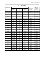
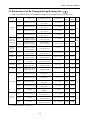
Parameter
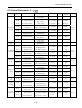
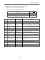
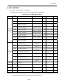
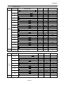
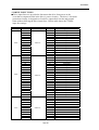
No.
LCD Display
(English)
Name
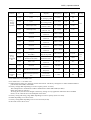
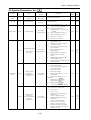
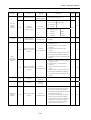
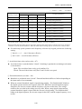
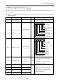
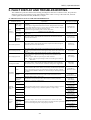
Un-13=0
None Opt. Card
Un-13
Option card code
Un-14
U phase current (IU)
conversion value
Un-15
W phase current (IW)
conversion value
Un-16
3 phase rectify current
(DIAC) conversion value
Un-17
ADC Reference Volt.
conversion value
Un-18
External Analog
Command VIN
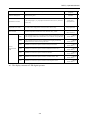
Un-14=1.00V
IU current
Un-15=1.00V
IW current
Un-16=1.00V
DIAC current
Un-17=2.50V
ADCHK Voltage
Un-18=10.00V
Voltage ~ Input
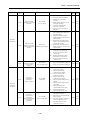
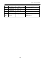
Un-19
External Analog
Command AIN
Un-19=20.0mA
Current ~ Input
Un-20
Multi-Function Analog
Input Command AUX
Un-20=10.00V
Multi-Fct. ~ Input
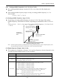
Unit
Descriptions
1
0:None of option card is installed
1:PA-M, PA-L, PA-C card is installed in CN2.
2~5:Reserved
6:PA-P (PROFIBUS) card is installed in CN2.
7:Reserved
8:PA-PID card is installed in CN2.
0.01V
Range:0.00V ~ 5.00V
z Un-14, Un-15 can be used to check DCCT
function.
z Un-16, Un-17 can be used to check ADC
function in the control board.
z Troubleshooting used
0.01V
Range:0.00V ~ 10.00V
0.1mA Range:0.0 ~ 20.0mA
0.01V
Range:0.00V ~ 10.00V
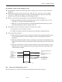
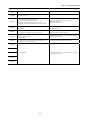
Range:-9.999 ~ +9.999
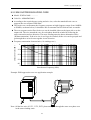
The display conversion unit depend on Bn-21 and
Bn-22.
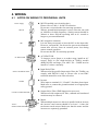
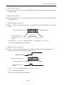
AUX
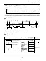
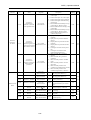
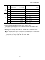
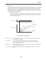
Un-21
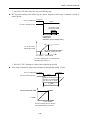
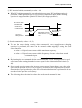
PID Detected Value after
display unit conversion
Un-21=1.000
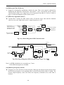
PID Detect
0.001
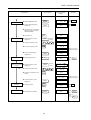
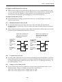
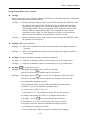
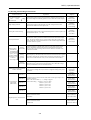
Aimed Value +
Detected
Value
PID
Frequency
Command
-
Bn-13
VIN
Bn-21/ Bn-22
AIN
PID detected Value
after unit conversion
(Un-21)
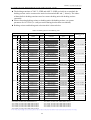
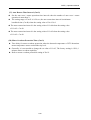
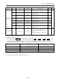
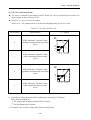
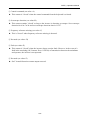
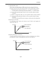
*1 The contents of Un-11 and Un-12 can be reset by Sn-03=1000 and 1001
Individually.
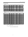
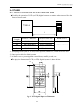
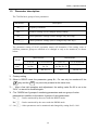
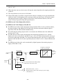
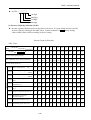
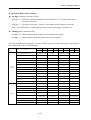
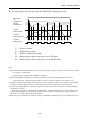
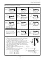
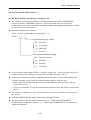
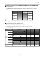
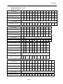
*2 The display status for JNEP-33 LED operator :
*3. The display status for JNEP-33 LED operator
OFF: OPEN
LIT : CLOSED
OFF: OPEN
LIT : CLOSED
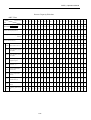
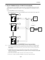
terminal 1
terminal 2
terminal 3
terminal 4
terminal 5
terminal 6
terminal 7
terminal 8
terminal R2A-R2C
terminal D01-DCOM
terminal R1A-R1C
2-67