1
User Manual for the
HE693SER300
Sequence of Events
Recorder Module
Second Edition
November 25, 2003
MAN0078-02
PREFACE
25 NOV 2003
PAGE 3
PREFACE
This manual explains how to use the Sequence of Events Recorder Module.
Copyright (C) 2003, Horner APG, LLC, 640 North Sherman Drive, Indianapolis, Indiana 46201. All rights
reserved. No part of this publication may be reproduced, transmitted, transcribed, stored in a retrieval
system, or translated into any language or computer language, in any form by any means, electronic,
mechanical, magnetic, optical, chemical, manual or otherwise, without the prior agreement and written
permission of Horner APG, LLC.
All software described in this document or media is also copyrighted material subject to the terms and
conditions of the Horner Software License Agreement.
Information in this document is subject to change without notice and does not represent a commitment on
the part of Horner APG, LLC.
Series 90-30 and Logicmaster are trademarks of GE Fanuc Automation North America, Inc.
DOS and MS-DOS are trademarks of Microsoft Corporation.
PAGE 4
25 NOV 2003
PREFACE
LIMITED WARRANTY AND LIMITATION OF LIABILITY
Horner APG, LLC ("HE") warrants to the original purchaser that the Sequence of Events Recorder Module
manufactured by HE is free from defects in material and workmanship under normal use and service.
The obligation of HE under this warranty shall be limited to the repair or exchange of any part or parts
which may prove defective under normal use and service within two (2) years from the date of
manufacture or eighteen (18) months from the date of installation by the original purchaser whichever
occurs first, such defect to be disclosed to the satisfaction of HE after examination by HE of the allegedly
defective part or parts. THIS WARRANTY IS EXPRESSLY IN LIEU OF ALL OTHER WARRANTIES
EXPRESSED OR IMPLIED INCLUDING THE WARRANTIES OF MERCHANTABILITY AND FITNESS
FOR USE AND OF ALL OTHER OBLIGATIONS OR LIABILITIES AND HE NEITHER ASSUMES, NOR
AUTHORIZES ANY OTHER PERSON TO ASSUME FOR HE, ANY OTHER LIABILITY IN CONNECTION
WITH THE SALE OF THIS SEQUENCE OF EVENTS RECORDER MODULE. THIS WARRANTY
SHALL NOT APPLY TO THIS SEQUENCE OF EVENTS RECORDER MODULE OR ANY PART
THEREOF WHICH HAS BEEN SUBJECT TO ACCIDENT, NEGLIGENCE, ALTERATION, ABUSE, OR
MISUSE. HE MAKES NO WARRANTY WHATSOEVER IN RESPECT TO ACCESSORIES OR PARTS
NOT SUPPLIED BY HE. THE TERM "ORIGINAL PURCHASER", AS USED IN THIS WARRANTY,
SHALL BE DEEMED TO MEAN THAT PERSON FOR WHOM THE SEQUENCE OF EVENTS
RECORDER MODULE IS ORIGINALLY INSTALLED. THIS WARRANTY SHALL APPLY ONLY WITHIN
THE BOUNDARIES OF THE CONTINENTAL UNITED STATES.
In no event, whether as a result of breach of contract, warranty, tort (including negligence) or otherwise,
shall HE or its suppliers be liable of any special, consequential, incidental or penal damages including,
but not limited to, loss of profit or revenues, loss of use of the products or any associated equipment,
damage to associated equipment, cost of capital, cost of substitute products, facilities, services or
replacement power, down time costs, or claims of original purchaser's customers for such damages.
To obtain warranty service, return the product to your distributor with a description of the
problem, proof of purchase, post paid, insured and in a suitable package.
ABOUT PROGRAMMING EXAMPLES
Any example programs and program segments in this manual or provided on accompanying diskettes are
included solely for illustrative purposes. Due to the many variables and requirements associated with any
particular installation, Horner APG cannot assume responsibility or liability for actual use based on the
examples and diagrams. It is the sole responsibility of the system designer utilizing the Sequence of
Events Recorder Module to appropriately design the end system, to appropriately integrate the Sequence
of Events Recorder Module and to make safety provisions for the end equipment as is usual and
customary in industrial applications as defined in any codes or standards which apply.
Note:
The programming examples shown in this manual are for
illustrative purposes only. Proper machine operation is the sole
responsibility of the system integrator.
PREFACE
Revisions to this Manual.
1.
Revised Table 4.1.
2.
Revised Section 4.7: LEDs.
25 NOV 2003
PAGE 5
PAGE 6
25 NOV 2003
PREFACE
PREFACE
25 NOV 2003
PAGE 7
TABLE OF CONTENTS
PREFACE ..........................................................................................................................................3
LIMITED WARRANTY AND LIMITATION OF LIABILITY .......................................................................4
ABOUT PROGRAMMING EXAMPLES ................................................................................................4
TABLE OF CONTENTS ......................................................................................................................7
CHAPTER 1: INTRODUCTION ...........................................................................................................9
1.1 HE693SER300 Product Description ...........................................................................................9
1.2 Overview of the Sequence of Events (See Figure 1.1).................................................................9
CHAPTER 2: INSTALLATION ........................................................................................................... 11
2.1
General............................................................................................................................... 11
2.2 CAN Interface.......................................................................................................................... 11
2.2 HE693SER300 Grounding Information ..................................................................................... 12
CHAPTER 3: CONFIGURATION SOFTWARE FOR THE HE693SER300 ........................................... 13
3.1
General............................................................................................................................... 13
3.2
Configuration Procedures..................................................................................................... 13
CHAPTER 4: OPERATION .............................................................................................................. 17
4.1 Functions ............................................................................................................................... 17
4.2 Recording Events and Updating Digital Output Modules (See Figure 1.1 for Overview) ............... 17
4.3 HE693SER300 Module CAN Messaging .................................................................................. 17
4.4 GPS Time Server (TIM100) ..................................................................................................... 18
4.5 Input Signal Specification (Received from GE Fanuc Digital Input Modules)................................ 18
4.6 Guidelines for Proper Input Signal Generation for Digital I/O Modules Used with the SER300 ...... 18
4.7 LED Indicators ......................................................................................................................... 19
APPENDIX A: GE FANUC SERIES 90-30 DISCRETE I/O MODULE SPECIFICATIONS ...................... 21
APPENDIX B: INPUT SIGNAL SPECIFICATIONS (CASE EXAMPLE) ................................................ 23
1
General .................................................................................................................................. 23
2
Proper Input Signal Generation................................................................................................ 23
3
Parameters for IC693MDL655 Digital Input Module (Case Example).......................................... 24
PAGE 8
25 NOV 2003
THIS PAGE INTENTIONALLY LEFT BLANK
PREFACE
CH. 1:
25 NOV 2003
PAGE 9
CHAPTER 1: INTRODUCTION
1.1 HE693SER300 Product Description
The HE693SER300 Sequence of Events Recorder Module (SER300) time stamps and records events
with a time resolution of one millisecond and resides in the CPU slot of a GE Fanuc 90-30 rack
(IC693CHS397 or IC693CHS391). The SER300 uses 200mA of current steady state, and draws 210 mA
of in-rush current. Each SER300 is able to scan up to 256 digital input points of GE Fanuc Digital I/O
Modules. Up to eight SER300 modules may be connected together on a Controller Area Network (CAN)
bus by using a corresponding number of GE Fanuc 90-30 racks. Each SER300 is capable of storing
1,000 time stamped events.
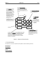
1.2 Overview of the Sequence of Events (See Figure 1.1)
The SER300 allows users to track and create a history log of events over a CAN bus. An event is defined
as any transition from ON to OFF (or OFF to ON) for one or more digital inputs. A CAN network consists
of up to eight SER300s along with one time server (e.g.; HE200TIM100) and one CAN data concentrator
(e.g.; HE693CDC300). A GE Fanuc CPU and Digital I\O Modules are also used in the applications. The
following explanation describes how the above equipment functions together to record events and allow
communication between remote I/O racks over a CAN bus:
a.
The CDC300 is responsible for retrieving data from the SER300 and providing the data to the GE
Fanuc CPU. The CDC300 also sends commands from the GE Fanuc CPU to the SER300. Upon
receiving a CAN message from the SER300 that an event has occurred, the CDC300 notifies the GE
Fanuc CPU and awaits instructions. The CPU, then, sends instructions to the CDC300. The CDC300
passes the instructions to the SER300 via the CAN network.
Examples of CAN message commands to the SER300 include the retrieval of event data and to
enable/disable event recording or to provide update information to the GE Fanuc Digital Output Modules.
b.
The CDC300 sends CAN message commands to the SER300 via the CAN network. The SER300
executes the commands and then provides acknowledgements to the CDC300.
c.
The TIM100 Time Server provides a stable 100 microsecond time reference to the CAN bus and
is used to keep the network’s SER300s in synchronization with each other. It also provides
synchronization with SER300s in other networks.
PAGE 10
25 NOV 2003
2. The SER300s scan up
to 256 input points of the
I\O modules to look for
events and to time stamp
them. The SER300 notifies
the CDC via a Fast
Message format. When
the CDC300 responds with
instructions, the SER300
acknowledges the
commands via a SMART
Message format .
The SER300 also provides
updates to the Digital
Output Modules if directed.
CH. 1
6. The GPS Time Server
(TIM100) provides a 100 µsec.
reference to keep the SER300s
synchronized. The reference is
sent on to the CAN Bus every one
second.
1. GE Fanuc Input Modules
receive inputs from various
sensory equipment, etc.
SATELLITES
HE500TIM100
GPS TIME
SERVER
SER300
IN
IN
OUT
GE FANUC I/O MODULES
SER300
IN
CDC300
CAN Bus
IN
OUT
GE FANUC
CPU
3. Upon detecting an event, the SER300 sends a Fast
Message to the CDC300 to indicate that an event has
occurred, etc. The CDC, then, notifies the GE Fanuc
CPU. When the GE Fanuc CPU responds with
instructions, the CDC300 sends them via a SMART
Message to the SER300.
4. The GE Fanuc CPU sends
instructions to the CDC300
indicating what it wants done
such as obtaining an event or
sending data to the GE Fanuc
Output Modules.
Figure 1.1 – Sequence of Events Recorder
1.3 Technical Assistance
For assistance or to check for periodic manual updates, contact the following resources.
North America:
(317) 916-4274
www.heapg.com
Europe:
(+) 353-21-4321-266
www.horner-apg.com
5. Digital Output
Modules are
updated by the
SER300 (if
commanded by the
GE Fanuc CPU) to
allow broadcasting
to remote
equipment.
CH. 2
25 NOV 2003
PAGE 11
CHAPTER 2: INSTALLATION
2.1
General
The SER300 Module plugs into the CPU slot of a GE Fanuc Series 90-30 rack. Consult the following for
wiring information. The information below contains wiring details for the SER300:
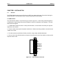
2.2 CAN Interface
The CAN Interface utilizes a 5-pin Phoenix-type connector (figure 2-1). When wiring modules together in
a CAN system, certain wiring rules must be followed in order for the system to work properly. The rules
below should be applied.
1. A CAN network should be wired in a daisy-chained fashion, such that there are exactly two physical
endpoints on the network.
2. The two nodes at the physical endpoints should have 120ohm terminating resistors connected across
“CAN-H” and “CAN-L.”
3. The data conductors (CAN-H and CAN-L) should be a high quality shielded twisted pair.
4. Only one end of the shield should be connected. Grounding both ends of the shield can cause ground
loops and induce noise.
V+
CAN_H
SHIELD
CAN_L
V-
Figure 2.1 - 5-Pin Phoenix Connector
PAGE 12
25 NOV 2003
CH. 2
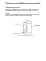
2.2 HE693SER300 Grounding Information
The SER300 must be connected to frame ground at the slot where it is installed. The following text and
figure represent the proper grounding technique for the SER300. Grounding this device is similar to
grounding a GE Fanuc CPU 351 and 352.
The connection from the SER300 to frame ground can be made using a green ground wire included with
the SER300.
The wire has a quick-slide connector on one end for connection to a mating terminal on the bottom of the
CPU, and a ring terminal on the other end for connection to a grounded enclosure.
Grounding Wire
HE693SER300
Panel Chassis
Figure 2.2 – Grounding SER300 to Panel Chassis
CH. 3
25 NOV 2003
PAGE 13
CHAPTER 3: CONFIGURATION SOFTWARE FOR THE HE693SER300
3.1
General
Prior to use, the HE693SER300 Sequence of Events Recorder Module needs to be configured with the
HECFG.EXE PC DOS tool. The software tool is shipped on diskette with the SER300. An IBMcompatible computer using DOS version 3.3 or higher is required to configure the SER300.
The purpose of the software tool (HECFG.exe) is to configure the HE693SER300 for use with the
HE693CDC300. This allows the devices to communicate via the CAN bus. The HE693CDC300 is
configured using Logicmaster 90 (LM90). (See the HE693CDC300 users manual for complete
configuration instructions).
3.2
Configuration Procedures
In order for the SER and the CDC (or other CAN devices) to communicate successfully on the CAN bus,
the baud rate and address must be configured properly. The CAN Node number (also known as the
address) can be set from 1 to 30. The CDC300 on the network must be configured with a different node
number (usually 30).
Baud Rate / Maximum Cable (in meters)
Baud Rate
Maximum Cable (m)
a.
125K
500
250K
250
500K
100
1Meg
25
Configuration of Node Number (Address)
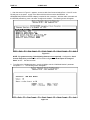
In order to configure a node number for the SER300, the HECFG.exe configuration software must be
used. To use the
software, simply go to the path in DOS where the program is located and type in HECFG. If
Communication Port 2 is to
be used, type in HECFG 2. The screen below should appear.
Figure 3.1
PAGE 14
25 NOV 2003
CH. 3
1. After the screen in Figure 3.1 appears, connect a cable from Communications Port 1 of the PC to the
RS-485 port on the power supply of the Series 90-30 rack that contains the SER300. An
HE693SNP232 (RS-485 to RS232 adapter) is needed for this connection. With the cable connected and
the SER300 powered up, press 2 to select “Configure the module”. The following screen will appear:
Figure 3.2
NOTE: For greater accuracy (if the following features are not required): Configure the “Send
Current Time Once per Second” to OFF and also configure the “Send Inputs on Change of
State” to OFF. See above screen.
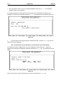
2.
To configure the CAN Node Number, move the highlight over the “CAN Node Number” parameter
and press Enter. The following screen will appear:
Figure 3.3
CH. 3
3.
25 NOV 2003
PAGE 15
Enter the address number for the connected HE693SER300 and press Enter. The CAN Node
address number is now configured.
To configure the baud rate, escape from the previous page to the configuration screen (Figure 3-2).
Highlight the CAN baud rate parameter and press Enter. The following screen will appear (Figure 3-4):
Figure 3.4
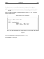
4.
Press the Space bar to toggle through the different baud rates. Press the Enter key when the
desired baud rate is highlighted.
Note: The baud rates must be the same for all the modules on the CAN network.
To configure the number of Digital Inputs, go to the configuration screen (Figure 3-2). Position the
highlight over the“Number of Input Bytes” parameter and press the Enter key. The following screen will
appear:
Figure 3.5
Enter in the maximum number of input bytes to be scanned and press the Enter key.
PAGE 16
25 NOV 2003
CH. 3
To configure the maximum number of Digital Outputs, go to the Configuration Screen (Figure 3-2).
NOTE: Each byte enables 8 input channels to be scanned. If fewer channels are found in the rack than
are configured, only the channels in the modules that are physically present in the rack are
scanned.
Place the highlight over the Number of Output Bytes Parameter. Press the Enter key. The following
screen will appear (Figure 3-6):
Figure 3.6
Enter in the maximum number of output bytes and press the Enter key.
The SER300 Module is now configured.
CH. 4
25 NOV 2003
PAGE 17
CHAPTER 4: OPERATION
4.1 Functions
The SER300 has three main functions:
a.
b.
c.
Digital Input event recording;
Digital Output updating;
CAN network communication.
A CAN network consists of up to eight SER300s along with one Time Server (HE200TIM100) and one
CAN Data Concentrator (such as the HE693CDC300). A GE Fanuc CPU and Digital I\O Modules are
also used in the applications.
4.2 Recording Events and Updating Digital Output Modules (See Figure 1.1 for Overview)
The sequence of events starts with the GE Fanuc Digital Input Module(s) receiving inputs from various
sensory equipment. The SER300 scans the Digital Input Module(s) to determine if an event has occurred.
(An event is defined as any transition from ON to OFF [or from OFF to ON] on one or more digital inputs.)
Upon detection of an event, the data is time stamped and recorded in the SER300’s Event Table. The
SER300 notifies the CDC300 of the event using a Fast Message format. The CDC300, then, notifies the
GE Fanuc CPU. The GE Fanuc CPU sends instructions such as having the CDC300 obtain an event
from the SER300 and for the SER300 to clear its Event Table.
If desired, the GE Fanuc CPU also sends update information to the Digital Output Modules via the
CDC300 and the SER300. This allows the Digital Output Modules to control to remote equipment.
Internal timing of the SER300s is maintained at a resolution of 100 microseconds by using the Horner
Electric TIM100. The TIM100 is a satellite-based time source which provides a stable time reference to
synchronize the SER300s in its network and to synchronize with SER300s that are in other networks.
4.3 HE693SER300 Module CAN Messaging
Two types of messages are used to exchange data between the SER300 and other equipment on the
CAN bus:
Fast messages and Smart messages.
1. Fast messages allow the transfer of raw data between CAN nodes and provide information such as
notifying the CDC300 of the time and current status of a digital input. They are sent in a single packet.
2. Smart messages establish a command/response protocol to allow the transfer of any type of data
between CAN nodes. Examples of Smart messages include commands such as telling the SER300 to
clear its event table or to enable the recording of events. Smart responses from the SER300 include
acknowledging the clearing of its event table or enabling the recording of events. Smart messages often
contain multiple packets of information.
The SER300 exchanges CAN messages with other CAN Nodes (such as the CDC300 Data Concentrator
Module) by sending an 11-bit Identifier and up to eight data bytes. The 11-bit Identifier specifies Message
Priority, Node ID, and Message Type. The data bytes depend on the Message Type.
PAGE 18
25 NOV 2003
CH.4
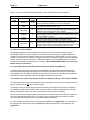
Table 4.1 shows the bit-mapped Smart Message Function Codes supported by the SER300:
Table 4.1 - Smart Message Function Codes
Data
Description
Count
Function
Code
Function
1
Get Event
9-40
2
Clear Event
Table
0
4
Enable Event
Recording
0
8
Get Status
0
16
Update
Outputs
1 to 8
32
Send Mask
4
Command sends 0 data bytes; Response returns Event Time Stamp in
8-byte packed BCD followed by 1 to 32 input data bytes.
Command tells the SER300 to clear its Event Table; Response
acknowledges clearing of Event Table.
Command is modal; if 4’s bit is 1, tells the SER300 to Enable Event
Recording; if 4’s bit is 0, tells SER300 to Disable Event Recording;
Response acknowledges the enable or disable.
Command tells the SER300 to send Fast Message Data Set 5, (2-byte
Status Register and 2 -byte Firmware Version Number); May be used
to verify SER300’s presence.
Command sends 1 to 8 data bytes containing Digital Output data;
Response acknowledges updating of the Digital Outputs.
Sends an input mask from the CDC to the SER. The mask allows
filtering certain channels of input so these inputs do not cause a
change of state. When a channel is filtered it does not cause an event
to be recorded and does not cause the input data to be sent.
4.4 GPS Time Server (TIM100)
The SER300 maintains an internal resolution of 100 microseconds via network messages from the
HE200TIM100 GPS Time Server (TIM100). The TIM100 receives timing inputs from GPS satellites and
provides a 100 microsecond reference for the proper synchronization of the SER300s. If there is a loss of
satellite communications, the TIM100’s back-up clock is able to maintain synchronization of the SER300s
that are a part of its network. However, the TIM100 is unable to sync up with SERs that are not a part of
its network until satellite communications are restored. (See the HE200TIM100 GPS Time Server User
Manual for more information.)
4.5 Input Signal Specification (Received from GE Fanuc Digital Input Modules)
In order to maintain the timing specifications on the SER300, the input signals received from the GE
Fanuc Digital Input Module(s) must meet specific waveform requirements. The waveform specifications
vary depending upon the Digital I/O Modules that are used. It is important to follow the general guidelines
listed below for proper signal generation for any Digital I/O Modules that are used:
4.6 Guidelines for Proper Input Signal Generation for Digital I/O Modules Used with the SER300
AC input modules add a large and varying delay to the input signal. If the error for input stamping must be
below 10 milliseconds, do not use AC input modules.
The voltage of the input signal should be within the module’s specifications and should be consistent for
all of the signals applied to the module. When voltages go above or below the specified value, the input
filtering and detection circuitry may alter the delay between the input and the SER300.
The rise and fall time of the input signals should be kept to a minimum value and should be consistent for
all of the signals applied to the module. The noise on the input signals should be kept to a minimum
value and should be consistent for all of the signals applied to the module.
For a list of Digital I\O Modules that can be used with the SER300, see Appendix A. For information on
the input waveform requirements (using IC693MDL655 Digital Input Module as a case example), see
Appendix B.
CH. 4
25 NOV 2003
PAGE 19
4.7 LED Indicators
a.
SER300 LEDs
The HE693SER300 features two bi-color LED indicators which provide information for front panel
diagnostics and indicate the current status of the unit. The two LED indicators are the NS Lamp
(Network Status) and the MS Lamp (Module Status).
a.
The MS Lamp shows the status of the module by indicating if the SER300s are being
synchronized by the GPS Time Source. It depicts if events have been captured and stored in memory.
The MS Lamp also indicates if the SER300’s Event Buffer is full. (1,000 events may be stored in each
SER300). It is important to note that if the Event Buffer is full, no new events are over written or stored in
memory.
b.
The NS Lamp indicates whether the network is operating normally or if the network is inoperative.
It also shows the reliability of the network by indicating if excessive CAN network errors are recorded.
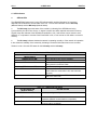
Tables 4.2 and 4.3 list the LED states for the MS Lamp and the NS Lamp:
Table 4.2 – SER300 MS LED Status
MS LED INDICATOR
MS LED STATES
(Module Status)
GREEN element ON:
Sync with GPS Time Source (Satellite)
GREEN element OFF:
No GPS Time Source sync.
RED element ON:
Events have been captured and are
being stored in the Events Table.
RED element OFF:
No events are being stored in the Events Table.
RED element FLASHING:
The event buffer is full.
(Note: When the event buffer is full, new events are
ignored.)
ORANGE
Occurs when GREEN and RED elements are both
ON at the same time.
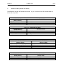
NS LED INDICATOR
(Network Status)
GREEN element ON:
Table 4.3 – SER300 NS LED Status
NS LED STATES
RED element ON:
RED element BLINKING (1 Hz)
Network operating normally
CAN network power not available or network
inoperative (Network communications not possible)
Excessive CAN network errors recorded.
(Communications unreliable)
PAGE 20
b.
25 NOV 2003
CH.4
Additional LEDs (CDC300 and TIM100)
The SER300 is used with the TIM100 and CDC300. For your convenience, the LED indicator states for
these units are provided.
NS LED INDICATOR
(Network Status)
RED element ON
GREEN element ON:
MS LED INDICATOR
(Module Status)
RED element ON:
GREEN element ON:
MS lamps OFF
Table 4.4 – TIM100 NS LED Status
NS LED STATES
Network fault
Network OK
Table 4.5 – TIM100 MS LED Status
MS LED STATES
During Initialization
Tracking satellites
Not tracking satellites
Table 4.6 – CDC300 NS LED Status
NS LED INDICATOR
NS LED STATES
(Network Status)
(Bi-Color LEDS)
GREEN element Flashes Irregularly:
CDC300 transmits data to CAN Network
RED element Flashes Irregularly
CDC300 receives data from CAN Network
RED element Blinks @ 1Hz rate
CAN Network down
RED element Solid ON
CAN connector is not powered
MS LED INDICATOR
(Module Status)
RED element OFF:
GREEN element OFF:
Table 4.7 – CDC300 MS LED Status
MS LED STATES
(Bi-Color LED)
MS LED not used – always OFF
MS LED not used – always OFF
PAGE 21
15 JULY 1998
APPENDIX A
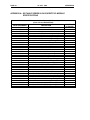
APPENDIX A: GE FANUC SERIES 90-30 DISCRETE I/O MODULE
SPECIFICATIONS
Table A1.1 - GE Fanuc Series 90-30 Discrete I/O Module Specifications
(Used with the HE693SER300)
NUMBER OF
CATALOG NUMBER
DESCRIPTION
I/O POINTS
IC693MDL230
Input – 120 VAC Isolated
8
IC693MDL231
Input – 240 VAC Isolated
8
IC693MDL240
Input – 120 VAC
16
IC693MDL241
Input - 24 VAC/DC Positive/Negative Logic
16
IC693MDL632
Input – 125 VDC Positive/Negative Logic
8
IC693MDL634
Input – 24 VDC Positive/Negative Logic
8
IC693MDL645
Input - 24 VDC Positive/Negative Logic
16
IC693MDL646
Input - 24 VDC Positive/Negative Logic, Fast
16
IC693ACC300
Input Simulator
8 or 16
IC693MDL310
Output – 120 VAC, 0.5A
12
IC693MDL330
Output – 120/240 VAC, 2 A
8
IC693MDL340
Output - 120 VAC, 0.5A
16
IC693MDL390
Output - 120/240 VAC Isolated, 2A
5
IC693MDL730
Output – 12/24 VDC Positive Logic, 2A
8
IC693MDL731
Output - 12/24 VDC Negative Logic, 2A
8
IC693MDL732
Output - 12/24 VDC Positive Logic, 0.5A
8
IC693MDL733
Output - 12/24 VDC Negative Logic, 0.5A
8
IC693MDL734
Output – 125 VDC Positive/Negative Logic, 1A
6
IC693MDL740
Output - 12/24 VDC Positive Logic, 0.5A
16
IC693MDL741
Output - 12/24 VDC Negative Logic, 0.5A
16
IC693MDL742
Output - 12/24 VDC Positive Logic, ESCP, 1A
16
IC693MDL930
Output – Relay, N.O., 4A Isolated
8
IC693MDL931
Output –Isolated Relay, N.C. and Form C, 8A
8
IC693MDL940
Output – Relay, N.O., 2A
16
IC693MAR590
Input/Output – 120 VAC Input, Relay Output
8/8
IC693MDR390
Input/Output – 24 VDC Input, Relay Output
8/8
IC693MDL653
Input – 24 VDC Positive/Negative Logic FAST
32
IC693MDL654
Input – 5/12 VDC (TTL)Positive/Negative Logic
32
IC693MDL655
Input – 24 VDC Positive/Negative Logic
32
IC693MDL750
Output – 12/24 VDC Negative Logic
32
IC693MDL751
Output – 12/24 VDC Positive Logic
32
IC693MDL752
Output – 5/24 VDC (TTL) Negative Logic, 0.5A
32
IC693MDL753
Output – 12/24 VDC Positive Logic, 0.5A
32
PAGE 22
25 NOV 2003
NOTES
APPENDIX A
APPENDIX B
25 NOV 2003
PAGE 23
APPENDIX B: INPUT SIGNAL SPECIFICATIONS (CASE EXAMPLE)
NOTE: The following case example is for provided for reference purposes only.
1
General
a. The information contained in the case example is for the Digital Input Module IC693MDL655.
b. Input signal specifications vary depending upon the Digital Input Module(s) selected.
c. For any Digital Input Module that is used, be sure to observe the “Guidelines for Proper Input Signal
Generation for Digital Input Modules Used with the SER300” in Chapter 4: Operation, Section 4.6.
Table B.1 - Input Signal Specification from the IC693mdl655
Required Input Signal Voltage
11.5 VDC > 25 VDC (Represents ON state.)
Minimum Rise Time of Input Signal
2
Approximately 25 µSec. minimum
Proper Input Signal Generation
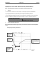
With an input that activates by rising from 0 to 24 volts in less than 25 microseconds, the input delay is
600 microseconds with a variation of approximately 30 microseconds (Assumes a constant temperature
of 20°C.)
Sample Input Delay Waveform
‚ Input
Turns ON to
24 Volts.
• Input OFF
0 Volts.
Figure 1
ƒ Input Module
Filtering Delay
620µSec as
shown.
„ Input Module "Tells"
the CPU the Input has
turned ON after some
delay.Figure 2
PAGE 24
25 NOV 2003
3
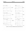
Parameters for IC693MDL655 Digital Input Module (Case Example)
a.
Voltage for the IC693MDL655
APPENDIX B
The electrical specifications for the IC693MDL655 Module specify that required input voltage must be
greater than 11.5 VDC and less than 25 VDC to represent an “ON” state. If the input signal follows these
guidelines, the response time through the input module will be consistent enough to be recorded
according to the HE693SER300 Module’s specifications (approximately 0.6 to 0.7 milliseconds). See
Figures 2, 3, and 4.
b.
Rise-Time and Fall Time
The rise-time and the fall-time of the input signal should be a minimum value (approximately 25
microseconds). An excessive rise or fall time will cause the input to turn on at an inconsistent level (both
time and voltage).
c.
Noise
Noise should be kept to a minimum on the input signals. Noise can cause the filtering circuitry on the
input modules to significantly increase or decrease the delay. When an input is OFF, the voltage
(including additive noise) should be below 3 volts. When an input is ON, the voltage (including destructive
noise) should be above 11.5 volts.
Figure 5 shows a simulation of noise from any AC power line (60Hz Sine wave) applied to the input of an
IC693MDL655E module. In this case, the noise produces a peak positive offset of 3 volts. This causes
little effect on the input delay.
Figure 6 is another simulation of power line noise. In this case, the noise has a peak positive offset of 7
volts. This causes the capacitors in the input filtering circuit to prematurely charge. When the input is
activated, the input delay is now less than 100 microseconds.
The above noise is an example of additive noise. Destructive noise can reduce the voltage on an input.
As seen in
Figure 1, reduced voltage can delay input activation by almost three milliseconds.
Note: Because noise can cause a relatively large variation in input delay, it is important to be
properly grounded and shielded and to have proper supply filtering for accurate time stamping.
APPENDIX B
25 NOV 2003
Figure 1
PAGE 25
Figure 2
Figure 3
Figure 5
Figure B.2 - Case Example: IC693MDL655 Digital Input Module Wave Forms
Figure 4
Figure 6
PAGE 26
25 NOV 2003
NOTES
APPENDIX B