1
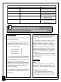
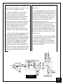
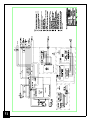
TP1
Parameter:
Jogging = +13.5 VDC
After contactor delay =
-6.0 VDC
Circuit common
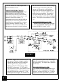
TP16 Parameter:
IR Comp
Level/range: 0 to –2.0 VDC
Condition:
Load and speed
dependant
11 Replacement Parts &
Component Substitution
11.1 COMPONENT SUBSTITUTION
Many components of a CHOICE® drive are
interchangeable with other CHOICE® models.
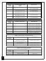
The following section lists CAROTRON's part
numbers and the manufacturer's part number
(if applicable) of the drive's major components.
This section can be used to order additional
parts or to determine if a component from one
drive may be substituted on another.
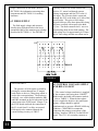
If needed, the CONTROL board can be
modified with minimal effort to operate any
model. The location of a zero Ohm resistor in
position R1, R2, or R3 determines the
CONTROL board model. Simply remove the
zero Ohm resistor, and replace it in the correct
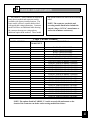
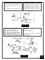
location. Please refer to TABLE 7 for
placement. The FUSE boards for all models
are identical, except for the wire lengths and
lug sizes. The CDC3150-000 FUSE board
requires longer wire lengths and larger ring
lugs than the other models
ALL SCR/DIODE isolated power modules
are rated at 1400 volts repetitive peak off state
and inverse voltage and have 1000
volts/microsecond dv/dt. There are 3 each per
model. The power modules listed in SECTION
11.5 are pin-for-pin compatible with all
CHOICE® drives. Consult the factory for
assistance in making substitutions with
components other than the recommended
spares listed below in SECTION 11.5.
A higher rated current and/or voltage
37
component may be substituted for any power
component. For example, the CDC320-000
model uses a 25 ampere, 1400 volt
SCR/DIODE module. If this module is not
available, a 55 ampere 1400 volt or a 25
ampere 1600 volt SCR/DIODE module could
be substituted. NOTE: A higher current rated
module will normally require a higher latching
current for the device to operate correctly.
Under light load conditions, this may cause the
SCR to momentarily drop out of conduction or
to not conduct at all. However, this problem is
easily eliminated by the application of load
and/or choosing a substitute device with a
minimal difference in the current rating.
11.2 PRINTED CIRCUIT ASSEMBLIES
CONTROL BOARD
Model CDC320-000……………..D10485-001
Model CDC340-000……………. D10485-002
Models CDC360-000 – CDC3150-000………..
……………...D10485-003
RELAY BOARD
Model CDC320-000-CDC360-000.
……………..D10488-000
Model CDC375-000……………..D10488-001
Model CDC3150-000…...……….D10488-002
FUSE BOARD
Model CDC320-000- CDC375-000…………...
…………….D10491-000
Model CDC3150-000……………D10491-001