1
User Manual for the
HE693BEM310
SDS Interface for the
GE Fanuc Series 90-30 PLC
Second Edition
31 July 2000
MAN0048-02
MAN0048-02
31 JUL 2000
PAGE 3
PREFACE
This manual explains how to use the Horner APG SDS Interface Module. This manual describes the
manner in which this module interfaces with the GE Fanuc Series 90 PLC and a network of SDS devices.
This document does not provide all the necessary details regarding the SDS network or the Series 90-30
PLC. Documentation from GE/MicroSwitch and GE Fanuc is necessary in order to successfully install a
complete system.
Copyright (C) 2000 Horner APG, LLC., 640 North Sherman Drive Indianapolis, Indiana 46201. All rights
reserved. No part of this publication may be reproduced, transmitted, transcribed, stored in a retrieval
system, or translated into any language or computer language, in any form by any means, electronic,
mechanical, magnetic, optical, chemical, manual or otherwise, without the prior agreement and written
permission of Horner APG, LLC.
All software described in this document or media is also copyrighted material subject to the terms and
conditions of the Horner Software License Agreement.
Information in this document is subject to change without notice and does not represent a commitment on
the part of Horner APG, LLC.
Series 90 and Logicmaster are trademarks of GE Fanuc North America.
SDS is a trademark of Honeywell MicroSwitch Division.
For user manual updates, contact Horner APG, Technical Support
Division, at (317) 916-4274 or visit our website at www.heapg.com.
PAGE 4
31 JUL 2000
MAN0048-02
LIMITED WARRANTY AND LIMITATION OF LIABILITY
Horner APG, LLC. ("HE-APG") warrants to the original purchaser that the SDS Module manufactured by
HE-APG is free from defects in material and workmanship under normal use and service. The obligation
of HE-APG under this warranty shall be limited to the repair or exchange of any part or parts which may
prove defective under normal use and service within two (2) years from the date of manufacture or
eighteen (18) months from the date of installation by the original purchaser whichever occurs first, such
defect to be disclosed to the satisfaction of HE-APG after examination by HE-APG of the allegedly
defective part or parts. THIS WARRANTY IS EXPRESSLY IN LIEU OF ALL OTHER WARRANTIES
EXPRESSED OR IMPLIED INCLUDING THE WARRANTIES OF MERCHANTABILITY AND FITNESS
FOR USE AND OF ALL OTHER OBLIGATIONS OR LIABILITIES AND HE-APG NEITHER ASSUMES,
NOR AUTHORIZES ANY OTHER PERSON TO ASSUME FOR HE-APG, ANY OTHER LIABILITY IN
CONNECTION WITH THE SALE OF THIS SDS Module. THIS WARRANTY SHALL NOT APPLY TO
THIS SDS Module OR ANY PART THEREOF WHICH HAS BEEN SUBJECT TO ACCIDENT,
NEGLIGENCE, ALTERATION, ABUSE, OR MISUSE.
HE-APG MAKES NO WARRANTY
WHATSOEVER IN RESPECT TO ACCESSORIES OR PARTS NOT SUPPLIED BY HE-APG. THE
TERM "ORIGINAL PURCHASER", AS USED IN THIS WARRANTY, SHALL BE DEEMED TO MEAN
THAT PERSON FOR WHOM THE SDS Module IS ORIGINALLY INSTALLED. THIS WARRANTY
SHALL APPLY ONLY WITHIN THE BOUNDARIES OF THE CONTINENTAL UNITED STATES.
In no event, whether as a result of breach of contract, warranty, tort (including negligence) or otherwise,
shall HE-APG or its suppliers be liable of any special, consequential, incidental or penal damages
including, but not limited to, loss of profit or revenues, loss of use of the products or any associated
equipment, damage to associated equipment, cost of capital, cost of substitute products, facilities,
services or replacement power, down time costs, or claims of original purchaser's customers for such
damages.
To obtain warranty service, return the product to your distributor with a description of the
problem, proof of purchase, post paid, insured and in a suitable package.
ABOUT PROGRAMMING EXAMPLES
Any example programs and program segments in this manual or provided on accompanying diskettes are
included solely for illustrative purposes. Due to the many variables and requirements associated with any
particular installation, Horner APG cannot assume responsibility or liability for actual use based on the
examples and diagrams. It is the sole responsibility of the system designer utilizing SDS Module to
appropriately design the end system, to appropriately integrate the SDS Module and to make safety
provisions for the end equipment as is usual and customary in industrial applications as defined in any
codes or standards which apply.
Note: The programming examples shown in this manual are for illustrative
purposes only. Proper machine operation is the sole responsibility of the
system integrator.
MAN0048-02
31 JUL 2000
PAGE 5
WHAT'S NEW?
This manual describes Release H of the HE693BEM310 SDS Remote I/O Interface Module. Also
defined, is Version 2.2 of the SDSCFG.EXE Configuration Utility, which is used to configure
HE693BEM310 modules. The following notes may be of interest to users of previously released
HE693BEM310 modules:
Release H of the HE693BEM310 module conforms to "MicroSwitch Specification GS 052 103 Issue 2",
which is entitled "SDS Application Layer Protocol Specification" Second Edition dated February 15, 1995.
1.
The above version of the SDS specification, differed from previous versions in its
definition of SDS device attribute 0 (Object Model Data Descriptor). This disparity
affected the compatibility between previously released HE693BEM310 modules, and
SDS I/O devices which have multiple inputs and/or multiple outputs (MIMO) per SDS
device address. With release H, this incompatibility has been resolved.
2.
HE693BEM310 release H now supports SDS I/O devices with up to 32 binary inputs
and/or 32 binary outputs.
3.
HE693BEM310 release H also supports extended (attribute 9) SDS I/O device
diagnostics, as defined in "MicroSwitch Specification GS 052 107 Issue 1.0", which is
entitled "SDS Component Modeling Specification" First Issue dated January 29, 1995.
This is accomplished by configuring the HE693BEM310 module for up to two additional
Series 90-30 %AI registers. The default number of %AI registers is 1, for backward
compatibility with earlier modules.
4.
The new SDSCFG.EXE Configuration Utility (Version 2.2) MUST be used to configure an
HE693BEM310 Release H module, and also supports HE693BEM310 Releases C
through G. In addition, configuration files created using SDSCFG.EXE Versions 2.0 or
2.1 are compatible with SDSCFG.EXE Version 2.2, thus ensuring backward compatibility
in this area.
5.
The behavior of the diagnostic LEDs has been altered to be more straightforward, and to
better assist the user in network troubleshooting.
6.
The firmware which supports the RS485 configuration serial port has been improved for
greater reliability.
PAGE 6
31 JUL 2000
MAN0048-02
Revisions to This Manual
This version (MAN0048-02) of the SDS Module User Manual contains the following revisions, additions
and deletions:
1. Converted manual into Word format.
2. Changed company name from Horner Electric, Inc. to Horner APG, LLC.
MAN0048-02
31 JUL 2000
PAGE 7
Table of Contents
PREFACE................................................................................................................................................3
ABOUT PROGRAMMING EXAMPLES ....................................................................................................4
Revisions to This Manual .........................................................................................................................6
CHAPTER 1: INTRODUCTION ...............................................................................................................9
1.1
Description................................................................................................................................ 9
1.2
Product Features ...................................................................................................................... 9
1.3
Front Panel Connections / Indications ......................................................................................11
CHAPTER 2: OPERATION ...................................................................................................................13
2.1
Module Configuration ...............................................................................................................13
2.1.1
Configuration Software Installation ....................................................................................13
2.2
Rack Configuration...................................................................................................................13
2.3
Module I/O Scanning................................................................................................................14
2.4
Module Diagnostics..................................................................................................................14
2.5
Bus Diagnostics .......................................................................................................................15
2.6
Device Level Diagnostics .........................................................................................................16
CHAPTER 3: CONFIGURATION...........................................................................................................17
3.1
Starting Up SDSCFG Under LogicMaster 90 ............................................................................17
3.2
Starting Up SDSCFG Independently.........................................................................................17
3.3
Checking Out the Screen .........................................................................................................18
3.4
Moving Around and Getting Help..............................................................................................18
3.5
Editing the “SDS Baud Rate” Parameter...................................................................................19
3.6
Editing the “PLC %I Ref Adr” Parameter...................................................................................19
3.7
Editing the “PLC %I Size” Parameter........................................................................................19
3.8
Editing the “PLC %Q Ref Adr” Parameter .................................................................................19
3.9
Editing the “PLC %Q Size” Parameter ......................................................................................19
3.10
Editing the “PLC %AI Ref Adr” Parameter .............................................................................20
3.11
Editing the “PLC %AI Size” Parameter ..................................................................................20
3.12
Editing the “PLC %AQ Ref Adr” Parameter ...........................................................................20
3.13
Editing the “PLC %AQ Size” Parameter ................................................................................20
3.14
Editing SDS Device I/O Maps ...............................................................................................20
3.15
Editing the “SDS Device %I Ref Adr” Parameter ...................................................................21
3.16
Editing the “SDS Device %I Size” Parameter ........................................................................21
3.17
Editing the “SDS Device %Q Ref Adr” Parameter..................................................................21
3.18
Editing the “SDS Device %Q Size” Parameter.......................................................................21
3.19
F1 - Help Function Key .........................................................................................................21
3.20
F2 - Load Configuration Function Key ...................................................................................22
3.21
F3 - Store Configuration Function Key ..................................................................................22
3.22
F4 - Automatic I/O ReMap Function Key ...............................................................................22
3.23
F10 - Zoom Into SDS Device I/O Map Function Key..............................................................23
3.24
Rack Configuration ...............................................................................................................23
PAGE 8
31 JUL 2000
NOTES
MAN0048-02
MAN0048-02
31 JUL 2000
PAGE 9
CH. 1
CHAPTER 1: INTRODUCTION
1.1
Description
The HE693BEM310 is an intelligent, remote I/O option module for the GE Fanuc Series 90-30
Programmable Logic Controller (PLC). The HE693BEM310 interfaces to standard Honeywell SDS I/O
devices (sensors and actuators), which may be up to 1500 feet away, and maps them directly into the
Series 90-30 I/O space.
The ladder programmer can treat the HE693BEM310 as a very high density (e.g. - 512 %I and 512 %Q)
digital I/O module. In addition to the digital I/O, the HE693BEM310 reports SDS bus diagnostics via one
%AQ and three %AI. For backwards compatibility with Rev. A-G, the default number of diagnostic %AI
registers is one. The additional two diagnostic registers contain device specific diagnostics not previously
available on Rev A-G.
Included with the HE693BEM310 module is a diskette containing the SDS Interface Module Configuration
Utility (SDSCFG.EXE). After installation, SDSCFG runs as a menu item under the LogicMaster 90 User
Command Menu and is used to configure the HE693BEM310 module as follows:
1.
Connects to the HE693BEM310’s integral serial port using the same PC/AT COM port used by
LogicMaster.
2.
Selects ranges of PLC %Is and PLC %Qs to be mapped to SDS I/O devices.
3.
Individually maps each SDS I/O Device to up to 32 PLC %Is and 32 PLC %Qs.
4.
Stores/loads complete I/O configurations to/from disk file or to/from the HE693BEM310 module.
5.
Prints complete configurations to printers with standard parallel interfaces or to network printers.
1.2
Product Features
;
;
;
;
;
;
;
;
Interfaces to SDS Remote I/O Devices 1 through 64
Supports single and multiple point digital SDS I/O Devices
Maps SDS remote I/O directly into Series 90-30 I/O
Reports SDS bus diagnostics with three (or one) %AI and one %AQ
References up to 512 %Is and 512 %Qs in 8-point increments
Configurable SDS Baud Rate from 125 KHz to 1 MHz
Configuration utility integrated with LogicMaster 90
Two diagnostics LEDs
PAGE 10
CH. 1
31 JUL 2000
Table 1.1 Module Specifications
Parameter
MIN
MAX
I/O Connector Specifications
SDS Power Voltage
11
25
SDS Power Load
15
SDS Signal Baud Rate
125
1000
SDS Signal Driver Fanout
0
64
Power Load Specifications
+5VDC (Logic)
175
+24VDC (Relay)
0
+24VDC (Isolated)
0
Environmental Specification
Operating Temperature
0
+60
Storage Temperature
-40
+85
Humidity (non-condensing)
5
95
UNITS
VDC
MA
KHz
Devices
mA
mA
mA
°C
°C
%RH
MAN0048-02
MAN0048-02
1.3
31 JUL 2000
PAGE 11
CH. 1
Front Panel Connections / Indications
Table 1.2 – Front Panel Indications
DESCRIPTION
Ladder Program is not Running
Ladder program is running and the HE693BEM310
ON
module’s self-test passed.
The HE693BEM310’s SDS to PLC I/O map is empty or
FLASHING
no mapped SDS devices are responding.
One or more unacknowledged SDS device faults have
OFF
been logged.
OFF
SDS device faults log is empty.
LED
Green
STATE
OFF
Green
Red
Red
Red
RS-485 Communications
The module RS-485 Comms port utilizes
the standard GE Fanuc pinout. The same
communications adapters may be utilized
to communicate to the SDS module as
are used to communicate to the Series
90-30 during Logicmaster configuration
and programming.
SDS Network Wiring
For network distances, wire selection,
termination, and other network wiring
instructions, see the SDS installation
information provided by GE/Micro Switch
Table 1.3 – SDS Network Wiring
Terminal
Signal
Description
Color
1
SHLD
Cable Shield
-
2
B-
SDS Signal -
White
3
B+
SDS Signal +
Black
4
V-
SDS Power -
Blue
5
V+
SDS Power +
Brown
PAGE 12
CH. 1
31 JUL 2000
NOTES
MAN0048-02
MAN0048-02
31 JUL 2000
PAGE 13
CH. 2
CHAPTER 2: OPERATION
Before the HE693BEM310 can be used in a Series 90-30 PLC installation, it must first be properly
configured.
There are two steps associated with configuring the HE693BEM310:
(1) Module Configuration
(2) Rack Configuration
2.1
Module Configuration
The purpose of Module configuration is to specify where SDS devices are mapped on the SDS network,
and how much PLC I/O is to be allocated to each one. Module configuration is accomplished via the
module’s integral serial port using a personal computer based configuration program. This configuration
program (SDSCFG.EXE) is included on a diskette shipped in the module box.
2.1.1
Configuration Software Installation
The configuration program works in conjunction with Logicmaster 90-30. BEFORE installing SDSCFG,
YOU MUST FIRST install LogicMaster 90, according to the instructions provided by GE Fanuc. After
successfully installing Logicmaster 90-30 on your personal computer hard drive, you may install SDSCFG
as follows:
1.
2.
3.
4.
Insert the diskette into the A: (or B:) drive.
Type A: (or B:) at the DOS prompt and press ENTER.
Type INSTALL [lm90path] at the DOS prompt and press ENTER.
Select the PC/AT serial port and parallel printer port to be used by SDSCFG when
prompted for them.
The [lm90path] optional parameter in step 3 is the DOS path where the LogicMaster 90 programming
software was installed. If omitted, [lm90path] is assumed to be C:\LM90. For example, if LogicMaster 90
was installed in D:\UTIL\LM90, type INSTALL D:\UTIL\LM90 at the DOS prompt, and then press ENTER.
To run the SDS Interface Configuration Utility, start LogicMaster 90, select the User Command Menu by
pressing F8, and use cursor keys to select “Configure an SDS Interface Module” from the User Command
Menu. See Chapter 3 for detailed instructions on using the SDSCFG configuration utility.
2.2
Rack Configuration
Rack configuration can be accomplished by either the Hand-Held Programmer (HHP) or by LogicMaster
90. The purpose of rack configuration is mainly to specify the total number and type of PLC I/O
references assigned to the module. I/O Reference data is transferred between the module and PLC CPU
each sweep. Rack configuration also is used to set some additional module parameters (SDS network
baud rate, etc.)
The I/O References used by the HE693BEM310 are as follows:
Quantity
0,8,16...512
0,8,16...512
1 (or 3)
1
Type
%I
%Q
%AI
%AQ
Size
Bit
Bit
Word
Word
Description
Remote Digital Inputs
Remote Digital Outputs
Fault Word
Fault Acknowledge Word
Direction
CPU<-Module
CPU->Module
CPU<-Module
CPU->Module
PAGE 14
CH. 2
31 JUL 2000
MAN0048-02
IMPORTANT: When configuring the PLC I/O Rack, the starting reference addresses and sizes for each
I/O type should EXACTLY match their equivalent global parameters previously configured into the
HE693BEM310 with the SDSCFG configuration program.
See Chapter 3 for detailed information on performing rack configuration via the Hand-Held Programmer
or LogicMaster 90.
2.3
Module I/O Scanning
When a configured HE693BEM310 module powers up, it scans the SDS network and makes a list of
responding SDS devices. “Missing Node” errors are placed in the “Error Log” for all SDS devices which
did not respond and which were previously configured (and enabled) via the SDSCFG configuration
utility.
For the configured devices which responded, the HE693BEM310 module initializes their I/O values as
follows:
1.
The initial ON/OFF states of all configured input devices are read and stored in the “%I
Input Table” for subsequent transfer to the Series 90-30 CPU during ladder execution.
2.
If the ladder program is not running, the ON/OFF states of all configured output devices
are initialized to OFF.
3.
Otherwise, if the ladder program is running, the ON/OFF states of all configured output
devices are initialized according to the “%Q Output Table” obtained from the Series 90-30
CPU.
After the initial device scan described above, the HE693BEM310 module communicates to SDS devices
as follows:
2.4
1.
If the module receives an unsolicited “Change of State” message from a configured SDS
input device, the “%I Input Table” is updated.
2.
If a bit in the “%Q Output Table” changes, the module sends a message to that bit’s
configured SDS output device to update the output’s state.
3.
Every 40 mS, the module interrogates one of the configured SDS devices (in a roundrobin fashion) to see if it is still available, if it has come back after an absence or if it has
any faults to report. Each configured SDS device is interrogated once every 2.56
seconds.
Module Diagnostics
The SDS Interface module, in addition to monitoring changes of state of SDS devices, also periodically
polls each device on the network to determine its status. This "round-robin" polling takes a maximum of
2.5 seconds to poll all the devices on the network. The polling continues as long as all devices are
healthy, but is halted when a device is encountered which reports an error.
The SDS Interface module contains an error log which is 1 (default) or 3 registers long. This error log is
maintained in the %AI registers assigned to the module. The first %AI register assigned to the module
contains the Bus Diagnostics information. If the module is assigned 3 %AI registers, the second two %AI
registers contain the device specific diagnostic data.
MAN0048-02
2.5
31 JUL 2000
PAGE 15
CH. 2
Bus Diagnostics
When an error is encountered, the module reports the faulted device's address along with an error code
to the first %AI register (called %AI1 for the purposes of this discussion) assigned to the module. The
error code is reported to the high byte (bits 9-16) of %AI1, and the device number is reported to the low
byte (bits 1-8). Listed below are the definitions of the 8 error bits which may be reported by a device:
Bit 9 - The SDS device’s ROM checksum test failed.
Bit 10 - The SDS device’s watchdog timer has expired.
Bit 11 - The SDS device has detected an idle bus.
Bit 12 - The SDS device is not healthy.
Bit 13 - The SDS device does not respond when interrogated.
Bit 14 - Future diagnostic bit
Bit 15 - Future diagnostic bit
Bit 16 - The SDS device’s EEPROM is not working properly.
To acknowledge the fault, the %AQ register assigned to the module should be toggled to a "1". If other
SDS devices are in error, %AI1 will scroll to the next faulted device. If no other devices are faulted, %AI1
will clear provided the error condition has been corrected.
If all error codes in the “Error Log” are zero, %AI1 will contain zero, and the red LED will be OFF,
indicating that there are no SDS bus faults to report.
If the “Error Log” contains non-zero error codes for one or more SDS devices, %AI1 will contain fault
information for one of the devices and the red LED will be ON. In this case, %AI1 will contain the error
code in its high byte and the SDS device number in its low byte as discussed previously.
At power-up, %AI1 will contain 0400H, until the auto-baud rate algorithm has completed and the
HE693BEM310 module has successfully communicated to at least one SDS device.
The application ladder program running on the PLC changes the %AQ fault acknowledge word from 0 to
1, to acknowledge the fault indicated by the %AI register. This action performs the following:
1.
A “Clear All Errors” message is sent to the SDS device whose address appears in the
%AI’s low byte.
2.
The device’s error code in the “Error Log” is cleared.
3.
If the “Error Log” contains no more non-zero error codes, %AI1 is set to zero, and the red
LED is turned OFF.
4.
Otherwise, %AI1 is loaded with “Error Log” fault information for the next device which has
a non-zero error code, and the red LED remains ON.
In this manner, the %AQ fault acknowledges word may be used to “scroll” the faults in the “Error Log”
through the %AI fault word. Of course, if the cause of a fault persists, it may show up again after all other
faults have been acknowledged.
PAGE 16
CH. 2
2.6
31 JUL 2000
MAN0048-02
Device Level Diagnostics
The BEM310 can support device level diagnostics provided that the module and rack have been
configured for 3 %AI analog input registers. The fault data is reported in the following format:
Table 2.1 – Fault Data
High Byte
Low Byte
Register
Byte 2
Byte 1
%AI2
Byte 4
Byte 3
%AI3
Byte 1 of %AI2 is contains the identical error code as %AI1. Bytes 2, 3, and 4 contain the device level
diagnostic data. Because the meaning of this data varies from device to device, consult the SDS device
manufacturer's documentation for more details.
MAN0048-02
31 JUL 2000
PAGE 17
CHAPTER 3: CONFIGURATION
To configure the HE693BEM310 module, a PC “compatible” computer is required. The supplied
SDSCFG.EXE utility may be run from floppy disk or may be copied to the PC’s hard disk and run from
there.
See page 20 for information on how to install SDSCFG so that it may be run as a User Command Menu
item under LogicMaster 90.
Using SDSCFG, complete HE693BEM310 module configurations may be created “offline” (without
connecting the PC to the module), and may be printed or saved to disk files for later retrieval.
To send a configuration to the HE693BEM310 module or to get a configuration from the module, it is
necessary to connect the PC to the module as follows:
3.1
1.
With the rack power off, plug the HE693BEM310 module into an open I/O slot of a GE
Fanuc Series 90-30 PLC rack.
2.
Plug an SNP to RS232 adapter (e. g. - HE693SNP232) into the 15-pin female D RS485
port on the HE693BEM310 module.
3.
Use a 9-pin female D to 9-pin female D “straight-through” cable, to connect the adapter to
one of the PC’s RS232 COM ports. If the PC is equipped with 25-pin COM ports, use a
standard 25-pin female to 9-pin male adapter at the PC end.
4.
Power up the Series 90-30 rack.
Starting Up SDSCFG Under LogicMaster 90
If SDSCFG was installed according to the instructions in Chapter 2, it may be run as a User Command
Menu item under LogicMaster 90.
In this case, start SDSCFG by first starting LogicMaster 90, then select the User Command Menu by
pressing F8, and finally use cursor keys to select “Configure an SDS Interface Module” from the User
Command Menu.
3.2
Starting Up SDSCFG Independently
To start SDSCFG as a “stand-alone” utility, type the following at the DOS prompt:
SDSCFG [/Cd] [/Ld] [/Vxx]<cr>
Where:
/Cd Optional COMd: port # where d = 1 to 4 (defaults to COM1:)
/Ld Optional LPTd: port # where d = 1 to 3 (defaults to LPT1:)
/Vx Optional color settings where x = 0 to 7F hexadecimal video attribute value (defaults to 1E; bright
yellow on blue)
<CR> Carriage Return (Enter)
PAGE 18
31 JUL 2000
MAN0048-02
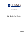
Figure 3.1 – Default Configuration
3.3
Checking Out the Screen
When SDSCFG starts, it shows a screen containing the HE693BEM310 module’s default configuration
and is ready for editing (see above).
The box in the upper-left-hand corner of the screen contains the SDSCFG utility’s title and version
number.
The edit box just below the title box contains the “global” SDS Baud Rate parameter. Note that this
parameter’s value is highlighted, indicating that it may be edited.
Below the SDS Baud Rate box is an edit box containing the eight PLC I/O Register “global” parameters.
On the right side of the screen, are 64 edit boxes which represent SDS Device Addresses 1 through 64.
The space to the left of each SDS Device Address is initially blank, indicating that none of the devices has
yet been mapped to any PLC I/O.
NOTE: SDS Device Addresses 65 through 126 are NOT supported.
The bottom-left of the screen shows function keys F1 through F4 along with brief descriptions of what
they do.
3.4
Moving Around and Getting Help
The PC’s cursor keys are used to change which parameter is highlighted (and therefore ready to be
edited). The TAB key switches between the edit boxes (2) on left side of the screen and the edit boxes
(64) on the right side of the screen.
The ESCape key is used to escape or abort the current activity.
Pressing the F1 function key gives a brief description and editing information for the highlighted
parameter.
MAN0048-02
3.5
31 JUL 2000
PAGE 19
Editing the “SDS Baud Rate” Parameter
To change the SDS Baud Rate, repeatedly press spacebar until the desired value is displayed.
The SDS Baud Rate parameter determines the maximum distance remote I/O devices may be located
from the HE693BEM310 according to the following table:
SDS Baud Rate
125 KHz
250 KHz
500 KHz
1 MHz
3.6
Maximum Distance
1500 Feet
600 Feet
300 Feet
75 Feet
Editing the “PLC %I Ref Adr” Parameter
To change the PLC %I Ref Adr, use the number keys to type in the new reference address and then
press the enter key.
The PLC %I Ref Adr parameter points to a block of PLC %I registers which will be available for mapping
to SDS inputs. The value of this parameter will be from 1 to 505 and must be byte-aligned.
If the user enters a value which is out of range or is not byte-aligned, it will be adjusted automatically to
the nearest “legal” value. When this happens, the user will be notified.
3.7
Editing the “PLC %I Size” Parameter
To change the PLC %I Size, use the number keys to type in the new number of %Is and then press the
enter key.
The PLC %I Size parameter determines the total number of PLC %Is which will be available for mapping
to SDS inputs. The value of this parameter will be from 0 to 512 and must be byte-aligned.
If the user enters a value which is out of range or is not byte-aligned, it will be adjusted automatically to
the nearest “legal” value. When this happens, the user will be notified.
3.8
Editing the “PLC %Q Ref Adr” Parameter
To change the PLC %Q Ref Adr, use the number keys to type in the new reference address and then
press the enter key.
The PLC %Q Ref Adr parameter points to a block of PLC %Q registers which will be available for
mapping to SDS outputs. The value of this parameter will be from 1 to 505 and must be byte-aligned.
If the user enters a value which is out of range or is not byte-aligned, it will be adjusted automatically to
the nearest “legal” value. When this happens, the user will be notified.
3.9
Editing the “PLC %Q Size” Parameter
To change the PLC %Q Size, use the number keys to type in the new number of %Qs and then press the
enter key.
PAGE 20
31 JUL 2000
MAN0048-02
The PLC %Q Size parameter determines the total number of PLC %Qs which will be available for
mapping to SDS outputs. The value of this parameter will be from 0 to 512 and must be byte-aligned.
If the user enters a value which is out of range or is not byte-aligned, it will be adjusted automatically to
the nearest “legal” value. When this happens, the user will be notified.
3.10
Editing the “PLC %AI Ref Adr” Parameter
To change the PLC %AI Ref Adr, use the number keys to type in the new reference address and then
press the enter key.
The PLC %AI Ref Adr parameter points to the PLC %AI register(s) which will be used to report SDS bus
faults. The value of this parameter will be from 1 to 1024.
If the user enters a value which is out of range, it will be adjusted automatically to the nearest “legal”
value. When this happens, the user will be notified.
3.11
Editing the “PLC %AI Size” Parameter
The number of %AIs is either 1 or 3. The default number is 1, for backward compatibility with module Rev
A-G. The value must be changed to 3 for device level diagnostics to be supported.
3.12
Editing the “PLC %AQ Ref Adr” Parameter
To change the PLC %AQ Ref Adr, use the number keys to type in the new reference address and then
press the enter key.
The PLC %AQ Ref Adr parameter points to the PLC %AQ which will be used to acknowledge SDS bus
faults. The value of this parameter will be from 1 to 256.
If the user enters a value which is out of range, it will be adjusted automatically to the nearest “legal”
value. When this happens, the user will be notified.
3.13
Editing the “PLC %AQ Size” Parameter
The number of %AQs is fixed at one, and can’t be edited.
3.14
Editing SDS Device I/O Maps
All SDS Devices which have mapped I/O, are marked with arrows
question marks (¿) as follows:
¾
?
¿
½¾, question marks (?) or upside down
= SDS Device’s I/O Map is OK
= SDS Device’s I/O overlaps another SDS Device’s I/O
= SDS Device’s I/O is out of PLC I/O Register range
When F10 is pressed, the PLC I/O Registers edit box changes to the SDS Device I/O Map for the
highlighted SDS device.
At this point, the UP and DOWN cursor keys select the SDS Device I/O Map parameter to be edited,
while the RIGHT and LEFT cursor keys change which SDS Device’s I/O Map is being displayed.
MAN0048-02
3.15
31 JUL 2000
PAGE 21
Editing the “SDS Device %I Ref Adr” Parameter
To change the SDS Device %I Ref Adr, use the number keys to type in the new reference address and
then press the enter key.
The SDS Device %I Ref Adr parameter points to the first PLC %I register which is mapped to the SDS
Device’s inputs. The value of this parameter will be from 1 to 512 and must be byte-aligned only if SDS
Device %I Size > 1 (multiple inputs).
If the user enters an “illegal” value, it will be adjusted automatically to the nearest “legal” value. When this
happens, the user will be notified.
3.16
Editing the “SDS Device %I Size” Parameter
To change the SDS Device %I Size, use the number keys to type in the new number of %Is and then
press the enter key.
The SDS %I Size parameter determines the number of PLC %Is which are mapped to the SDS Device’s
inputs and will be from 0 to 32.
If the user enters an “illegal” value, it will be adjusted automatically to the nearest “legal” value. When this
happens, the user will be notified.
3.17
Editing the “SDS Device %Q Ref Adr” Parameter
To change the SDS Device %Q Ref Adr, use the number keys to type in the new reference address and
then press the enter key.
The SDS Device %Q Ref Adr parameter points to the first PLC %Q register which is mapped to the SDS
Device’s outputs. The value of this parameter will be from 1 to 512 and must be byte-aligned only if SDS
Device %Q Size > 1 (multiple outputs).
If the user enters an “illegal” value, it will be adjusted automatically to the nearest “legal” value. When this
happens, the user will be notified.
3.18
Editing the “SDS Device %Q Size” Parameter
To change the SDS Device %Q Size, use the number keys to type in the new number of %Qs and then
press the enter key.
The SDS %Q Size parameter determines the number of PLC %Qs which are mapped to the SDS
Device’s outputs and will be from 0 to 32.
If the user enters an “illegal” value, it will be adjusted automatically to the nearest “legal” value. When this
happens, the user will be notified.
3.19
F1 - Help Function Key
As mentioned before, the F1 function key gives a brief description and editing information for any
highlighted parameter.
PAGE 22
3.20
31 JUL 2000
MAN0048-02
F2 - Load Configuration Function Key
The F2 key is used to get a complete configuration from a disk file or from an HE693BEM310 module.
When the F2 function key is pressed, it brings up the following sub-menu:
Load configuration from disk.
Load configuration from module.
Use the cursor keys to highlight the desired choice and then press enter.
If “Load configuration from disk.” is selected, SDSCFG will ask for a filename. Type in the name of a file
previously created via the F3 key (without extension), and then press enter. If in and the screen will be
updated with the new configuration.
If “Load configuration from module.” is selected, SDSCFG will attempt to communicate to the
HE693BEM310 module and, if successful, will read in the module’s current configuration and will update
the PC screen with the new configuration.
3.21
F3 - Store Configuration Function Key
The F3 key is used to store a complete configuration to a disk file or to an HE693BEM310 module or to
print a configuration. When the F3 function key is pressed, it brings up the following sub-menu:
Store configuration to disk.
Store configuration to module.
Send configuration to printer.
Use the cursor keys to highlight the desired choice and then press enter.
If “Store configuration to disk.” is selected, SDSCFG will ask for a filename. Type in a valid DOS filename
without extension and then press enter. The configuration currently shown on the PC screen will then be
written to the file. If the file already exists it will be overwritten; otherwise, it will be created.
If “Store configuration to module.” is selected, SDSCFG will attempt to communicate to the
HE693BEM310 module and, if successful, will send the configuration currently shown on the PC screen
to the module.
If “Send configuration to printer.” is selected, SDSCFG prints (up to 9 pages) the configuration currently
shown on the PC screen.
*** IMPORTANT NOTE ***
Note that if “Send configuration to module.” is successful, the module will store the new configuration in
its EEPROM. However, the new configuration will not take effect until the next time the PLC rack powers
up. This is necessary to accommodate the rack configuration procedure described in Section 3.24.
3.22
F4 - Automatic I/O ReMap Function Key
The F4 key automatically adjusts SDS Device %I Ref Adr and SDS Device %Q Ref ADR parameters for
ALL 64 SDS devices, in an effort to eliminate any “Overlap” or “Out of PLC I/O Register Range” errors
that may exist, and to minimize the amount of PLC I/O required.
The remapping is done in two stages.
MAN0048-02
31 JUL 2000
PAGE 23
All multiple input and/or output SDS I/O Devices are remapped first, since their reference addresses must
be byte-aligned.
Then, all single input and/or output SDS I/O Devices are remapped. The single point SDS devices can fill
“gaps” caused by the multiple point SDS device’s byte alignment requirement.
When remapping is complete, a summary is displayed showing the highest PLC %I and %Q which are
now mapped to SDS I/O.
*** CAUTION ***
The F4 function key should be used primarily during initial application development. Since F4 has the
ability to change ALL SDS Device I/O Map parameters, it should be used with caution as a maintenance
tool. It’s a good idea to save the previous configuration on disk and get a printout of it before using F4.
3.23
F10 - Zoom Into SDS Device I/O Map Function Key
Pressing the F10 key, when one of the 64 SDS Device I/O Map edit boxes is highlighted, zooms into the
Device’s I/O map for editing.
8.
3.24
Download the configuration to the Series 90-30 rack.
Rack Configuration
As mentioned previously, rack configuration can be accomplished via the Hand-Held Programmer (HHP)
of via LogicMaster 90.
In either case, it is important to perform module configuration first.
The following sequence may be used to configure the Series 90-30 rack for an HE693BEM310 module
via the Hand-Held Programmer (HHP):
1.
With the rack power off, plug the HE693BEM310 module into an open I/O slot of a GE
Fanuc Series 90-30 PLC rack.
2.
Power up the Series 90-30 rack.
3.
Press MODE, 4, ENTER to get into configuration mode.
4.
Press DOWN ARROW repeatedly until the HHP’s LCD display shows the slot containing
the HE693BEM310 module.
5.
If display does not show the slot as EMPTY, press DEL, ENTER to empty it.
6.
Press READ, ENTER and optionally set the desired PLC start addresses for the module’s
%AI, %AQ, %I and %Q registers.
The following sequence may be used to configure the Series 90-30 rack for an HE693BEM310 module
via LogicMaster 90:
1.
Start up the LogicMaster 90 Configuration Package.
PAGE 24
31 JUL 2000
MAN0048-02
2.
Use the Foreign Module screen to configure the desired Series 90-30 slot for an
HE693BEM310 module.
3.
Set number of %AIs to 1 or 3 and number of %AQs to 1. These values must match the
values previously selected during module configuration.
4.
Set number of %Is to the same number previously selected during module configuration.
5.
Set number of %Qs to the same number previously selected during module configuration.
6.
Set the desired PLC start addresses for the module’s %AI, %AQ, %I and %Q registers.
7.
Set the Byte 1 parameter on right side of screen to 1; bytes 2 through 16 should be zero.
8.
Download the configuration to the Series 90-30 rack.
9.
Power down the Series 90-30 rack.
10.
With the rack power off, plug the HE693BEM310 module into the Series 90-30 slot
selected during step 2.
11.
Power up the Series 90-30 rack.