1
Operator
Interface Units
Release 3.4
User Manual, for
HE693OIU057, HE693OIU157, HE693OIU177,
HE693OIU277, HE693OIU327, HE693OIU357 and HE693OIU367
Revision B or later
ATTENTION READER: REVISION PAGES ATTACHED
AFTER PAGE A-16.
12-10-97
MAN0066-01
Page ii
PREFACE
PREFACE
Page iii
PREFACE
This manual explains how to use the Horner APG Operator Interface Units for use with the GE
Fanuc Series 90 and CEGELEC Alspa 8000 family of Programmable Logic Controllers.
Copyright (C) 2000 Horner APG, LLC., 640 N. Sherman Dr., Indianapolis Indiana 46201-3899.
All rights reserved. No part of this publication may be reproduced, transmitted, transcribed, stored
in a retrieval system, or translated into any language or computer language, in any form by any
means, electronic, mechanical, magnetic, optical, chemical, manual or otherwise, without the prior
agreement and written permission of Horner APG, LLC.
Information in this document is subject to change without notice and does not represent a
commitment on the part of Horner APG, LLC.
Series 90 and Logicmaster are trademarks of GE Fanuc Automation North America Inc.
Alspa 8000 and P8 are Trademarks of CEGELEC
Page iv
PREFACE
LIMITED WARRANTY AND LIMITATION OF LIABILITY
Horner APG, LLC. ("HE") warrants to the original purchaser that the Operator Interface Unit
manufactured by HE is free from defects in material and workmanship under normal use and
service. The obligation of HE under this warranty shall be limited to the repair or exchange of any
part or parts which may prove defective under normal use and service within two (2) years from the
date of manufacture or eighteen (18) months from the date of installation by the original purchaser
whichever occurs first, such defect to be disclosed to the satisfaction of HE after examination by
HE of the allegedly defective part or parts. THIS WARRANTY IS EXPRESSLY IN LIEU OF ALL
OTHER WARRANTIES EXPRESSED OR IMPLIED INCLUDING THE WARRANTIES OF
MERCHANTABILITY AND FITNESS FOR USE AND OF ALL OTHER OBLIGATIONS OR
LIABILITIES AND HE NEITHER ASSUMES, NOR AUTHORIZES ANY OTHER PERSON TO
ASSUME FOR HE, ANY OTHER LIABILITY IN CONNECTION WITH THE SALE OF THIS
OPERATOR INTERFACE UNIT. THIS WARRANTY SHALL NOT APPLY TO THIS OPERATOR
INTERFACE UNIT OR ANY PART THEREOF WHICH HAS BEEN SUBJECT TO ACCIDENT,
NEGLIGENCE, ALTERATION, ABUSE, OR MISUSE. HE MAKES NO WARRANTY WHATSOEVER IN RESPECT TO ACCESSORIES OR PARTS NOT SUPPLIED BY HE. THE TERM
"ORIGINAL PURCHASER", AS USED IN THIS WARRANTY, SHALL BE DEEMED TO MEAN
THAT PERSON FOR WHOM THE OPERATOR INTERFACE UNIT IS ORIGINALLY INSTALLED.
THIS WARRANTY SHALL APPLY ONLY WITHIN THE BOUNDARIES OF THE CONTINENTAL
UNITED STATES.
In no event, whether as a result of breach of contract, warranty, tort (including negligence) or
otherwise, shall HE or its suppliers be liable of any special, consequential, incidental or penal
damages including, but not limited to, loss of profit or revenues, loss of use of the products or any
associated equipment, damage to associated equipment, cost of capital, cost of substitute
products, facilities, services or replacement power, down time costs, or claims of original
purchaser's customers for such damages.
To obtain warranty service, return the product to your distributor with a description of the problem,
proof of purchase, post paid, insured and in a suitable package.
PREFACE
Page v
ABOUT THE PROGRAM EXAMPLES
The example programs and program segments in this manual are included solely for illustrative
purposes. Due to the many variables and requirements associated with any particular installation,
Horner cannot assume responsibility or liablity for actual use based on the examples and
diagrams. It is the sole responsibility of the system designer utilizing the Operator Interface Unit
to appropriately design the end system, to appropriately integrate the Operator Interface Unit and
to make safety provisions for the end equipment as is usual and customary in industrial
applications as defined in any codes or standards which apply.
Page vi
PREFACE
TABLE OF CONTENTS
CHAPTER 1: INTRODUCTION
1.1
1.2
1.3
1.4
1.5
1.6
Why an Operator Interface Unit? .
.
Why a Horner Electric Operator Interface Unit?
About this Manual .
.
.
.
OIU Revision Levels
.
.
.
Revision A .
.
.
.
Revision B .
.
.
.
Revision C .
.
.
.
Features
.
.
.
.
.
Model Specifications
.
.
.
.
.
.
.
.
.
.
.
.
.
.
.
.
.
.
.
.
.
Page 1-1
Page 1-1
Page 1-2
Page 1-2
Page 1-2
Page 1-2
Page 1-2
Page 1-2
Page 1-4
.
.
.
.
.
.
.
.
.
.
.
.
Page 2-1
Page 2-1
Page 2-2
Page 2-3
Page 2-4
Page 2-4
.
.
.
.
.
.
.
.
.
.
.
.
.
.
.
.
Page 3-1
Page 3-1
Page 3-2
Page 3-2
Page 3-3
Page 3-3
Page 3-4
Page 3-4
Page 3-4
Page 3-6
Page 3-7
Page 3-8
Page 3-9
Page 3-9
Page 3-10
Page 3-12
CHAPTER 2: SCREEN UTILIZATION
2.1
2.2
2.3
2.4
2.5
2.6
Concept of "Screens"
Types of Screens .
Screen Access
.
Making a Screen "Map"
Passwords .
.
Operator Interface Setup
.
.
.
.
.
.
.
.
.
.
.
.
.
.
.
.
.
.
CHAPTER 3: APPLICATION DEVELOPMENT
3.1
3.2
3.3
3.4
3.5
3.6
3.7
3.8
Autorun and Setup Modes .
.
.
.
Using the OIU to Display PLC Data
.
.
3.2.1 Data Field Type
.
.
.
.
3.2.2 Block Number
.
.
.
.
3.2.3 Reference Type and Address
.
.
3.2.4 Range.
.
.
.
.
.
3.2.5 Base .
.
.
.
.
.
Function Keys
.
.
.
.
.
3.3.1 Function Keys as Momentary Pushbuttons
3.3.2 Function Keys as Macros .
.
.
3.3.3 Function Keys Used for PLC Data Editing
Controlling Screen Selection with the Trigger Register
Print Register & Print Status Register .
.
Text Tables .
.
.
.
.
.
Floating Point Values
.
.
.
.
Calendar Clock
.
.
.
.
.
PREFACE
Page vii
CHAPTER 3 (CONTINUED)
3.9
3.10
3.11
3.12
3.13
3.14
3.15
The LED Register .
The Expansion Register
The Keypad Mask .
Multidrop Applications
.
.
.
.
.
.
.
.
.
.
.
.
.
.
.
.
Page 3-12
Page 3-12
Page 3-13
Page 3-13
SNP or SNPX Protocol
.
.
.
SNPX Multidrop Using the PLC ID Table .
.
.
.
.
Page 3-13
Page 3-13
SNP Optimization .
Serial Pass Through
Definable Characters
.
.
.
.
.
.
.
.
.
.
.
.
.
.
.
.
.
.
.
Page 3-14
Page 3-15
Page 3-15
Menu Selections
.
.
.
Key Assignments .
.
.
Access PLC Data .
.
.
Cfg Screens .
.
.
.
Cfg Text Tables
.
.
.
Cfg Func Key
.
.
.
Cfg Float Scale
.
.
.
Cfg High Screen
.
.
.
Cfg Passwords
.
.
.
Cfg LED Reg .
.
.
.
Cfg Trigger Reg
.
.
.
Cfg CPU Address .
.
.
Cfg Com Port
.
.
.
Cfg Prn Port .
.
.
.
Adjust Display
.
.
.
Set Clock
.
.
.
.
Enter Autorun
.
.
.
Hand Held Programmer Emulation
Run Self Test
.
.
.
.
.
.
.
.
.
.
.
.
.
.
.
.
.
.
.
.
.
.
.
.
.
.
.
.
.
.
.
.
.
.
.
.
.
.
.
.
.
.
.
.
.
.
.
.
.
.
.
.
.
.
.
.
.
.
.
.
Page 4-1
Page 4-1
Page 4-2
Page 4-2
Page 4-4
Page 4-5
Page 4-6
Page 4-6
Page 4-6
Page 4-7
Page 4-7
Page 4-8
Page 4-8
Page 4-8
Page 4-9
Page 4-9
Page 4-10
Page 4-10
Page 4-10
CHAPTER 4: THE KEYPAD SETUP MENU
4.1
4.2
4.3
4.4
4.5
4.6
4.7
4.8
4.9
4.10
4.11
4.12
4.13
4.14
4.15
4.16
4.17
4.18
4.19
Page viii
PREFACE
CHAPTER 5: SOFTWARE CONFIGURATION
5.1
5.2
5.3
5.4
5.5
5.6
5.7
5.8
5.9
5.10
5.11
5.12
5.13
5.14
5.15
System Requirements
.
.
.
Connecting the Personal Computer to the OIU
Invoking the Software from DOS .
.
Program Organization
.
.
.
The Main Menu
.
.
.
.
The Screen Menu .
.
.
.
.
.
.
.
.
.
.
.
.
.
.
.
Page 5-1
Page 5-1
Page 5-1
Page 5-2
Page 5-3
Page 5-4
5.6.1 Screen Chaining
.
The Text Table Menu
.
The Function Key Menu .
High Screen Menu .
.
Password Menu
.
.
Miscellaneous Register Menu
The Clock Menu
.
.
The Autorun Menu .
.
Floating Point Scale Setup Menu
File Menu
.
.
.
.
.
.
.
Page 5-5
.
.
.
.
.
.
.
.
.
.
.
.
.
.
.
.
.
.
.
.
.
.
.
.
.
.
.
.
.
.
.
.
.
.
.
.
Page 5-6
Page 5-6
Page 5-8
Page 5-8
Page 5-9
Page 5-10
Page 5-10
Page 5-10
Page 5-11
.
.
.
.
.
.
.
.
.
.
Page 6-1
Page 6-2
Page 6-2
Page 6-3
Page 6-3
.
.
.
Page 6-4
Page 6-4
Page 6-5
CHAPTER 6: AUTORUN MODE
SECTION A -- UNITS WITH NUMERIC KEYPADS
6A.1
6A.2
6A.3
6A.4
6A.5
Changing Screens .
.
.
.
Monitoring and/or Changing PLC Data .
Function Key Operation .
.
.
Setting the Calendar Clock and Contrast .
Exiting Autorun Mode
.
.
.
SECTION B -- UNITS WITHOUT NUMERIC KEYPADS
6B.1 Changing Screens .
.
.
6B.2 Monitoring and/or Changing PLC Data
6B.3 Function Key Operation .
.
.
.
.
.
.
.
PREFACE
Page ix
CHAPTER 7: APPLICATION EXAMPLES
7.1
7.2
7.3
7.4
7.5
Changing Screens with a Function Key .
.
Emulating a Selector Switch with a Function Key
Enunciating Prioritized Alarms
.
.
.
Prompting Data Entry .
.
.
.
.
Printing Hourly Production Data .
.
.
APPENDIX A: INSTALLATION INFORMATION
A.1
Mounting
A.2
Providing Power
A.3
Communications Wiring
A.4
Placing the Module Into Service
.
.
.
.
.
Page 7-1
Page 7-1
Page 7-2
Page 7-4
Page 7-5
Page x
PREFACE
Pagevi
PREFACE
TABLE OF CONTENTS - GENIUS SUPPLEMENT
CHAPTER 1: INTRODUCTION
1.1
1.2
1.3
1.4
1.5
1.6
1.7
AboutthisManualSupplement .
.
.
The Genius Network .
.
.
.
The Advantages of Genius Operator Interface
The OIU as a Genius Device
.
.
Genius Data .
.
.
.
.
Model Features
.
.
.
.
Model Specifications
.
.
.
.
.
.
.
.
.
.
.
.
.
.
.
.
.
Page1-1
Page1-1
Page 1-1
Page 1-1
Page 1-2
Page 1-3
Page 1-4
Using the Genius OIU to Display PLC Data
.
.
Page 2-1
2.1.1 Block Number
2.1.2 Reference Type
.
.
.
.
.
.
.
.
.
.
Page 2-1
Page 2-1
Function Keys
.
.
.
.
.
Page 2-2
2.2.1 Function Keys as Momentary Pushbuttons
.
Page 2-2
Using a Genius OIU with the Series 90-30 PLC .
Using a Genius OIU with the Series 90-70 PLC .
.
.
Page 2-2
Page 2-4
CHAPTER 2: APPLICATION DEVELOPMENT
2.1
2.2
2.3
2.4
.
CHAPTER 3: THE KEYPAD SETUP MENU
3.1
3.2
3.3
GeniusMenuSelections
GeniusSetup .
.
Cfg Dgram Frq .
.
.
.
.
.
.
.
.
.
.
.
.
.
.
.
.
Page3-1
Page3-1
Page3-2
.
.
.
.
.
.
Page4-1
Page4-1
CHAPTER 4: SOFTWARE CONFIGURATION
4.1
4.2
MiscellaneousRegisterMenu .
The Autorun Menu
.
.
.
.
APPENDIX A: INSTALLATION INFORMATION
A.1
A.2
A.3
A.4
Mounting
Providing Power
Communications
Placing the OIU Into Service
CHAPTER 1: INTRODUCTION
Page 1-1
CHAPTER 1: INTRODUCTION
Congratulations on your purchase of a Horner Electric Operator Interface Unit (OIU)! Horner Electric Operator
Interfaces can provide a valuable window into your GE Fanuc Programmable Controller or Genius Distributed I/O
application.
1.1
Why an Operator Interface Unit?
Programmable Logic Controllers offer industrial users an incredibly flexible electrical control system. The ability
of the PLC to allow users to make significant changes in machine operation without the need for extensive rewiring
has been long appreciated, in large and small PLCs alike. In addition to machine control, other areas of PLC
integration have not been as fully utilized. One under-utilized area, especially with smaller systems, is the PLC’s
diagnostic and data handling capabilities. These capabilities must be accessed via a PLC's human interface, or
Man Machine Interface (MMI). With the proper MMI, PLC information can be readily available to a machine operator,
allowing PLCs to be used as a valuable tool for machine diagnostics, operational prompting, data logging, etc.
With small PLC systems in particular, cost is a large consideration. Traditionally, cost barriers have limited the
useage of advanced MMIs with small PLCs. The MMIs most commonly used with PLCs are non-flexible hard-wired
pushbuttons, pilot lights, and thumbwheel switches. These systems are fairly low in cost, but are inflexible and
offer little diagnostics or other capabilities.
A modern Operator Interface Unit (OIU) however, can provide even users of small PLCs with a powerful, flexible, costeffective instrument for PLC data access.
With a Horner Electric Operator Interface Unit you can:
1.
Monitor and/or change machine setpoint and other data,
2.
Replace up to 12 non-critical hard-wired pushbuttons,
3.
Enunciate machine alarm conditions as detected by the PLC,
4.
Prompt operators with the proper machine operation sequence,
5.
Log machine alarms and/or data to a serial printer.
Horner Electric OIUs have the versatility to perform all of the above functions, yet are easy to set up and use.
1.2
Why a Horner Electric Operator Interface Unit?
At Horner Electric, we specialize in products which complement GE Fanuc PLC products such as the Series 90
PLCs and Genius Distributed I/O System. Because we specialize, we are able to focus on providing Operator
Interface Products which are designed to take full advantage of some of the unique characteristics of a GE Fanuc
PLC product.
As a result of our specialization, we have developed considerable expertise with GE Fanuc PLC products. Our staff
not only understands operator interface operation and data access, but has a thorough understanding of the PLC
backplane, I/O bus, and Series 90 ladder logic programming. This wealth of knowledge and experience is unique
among GE Fanuc Operator Interface manufacturers, and allows our technical staff to provide you with excellent
technical suppport.
Page 1-2
1.3
CHAPTER 1: INTRODUCTION
About this Manual
This manual describes the operation of Horner Electric’s Release 3.4 Operator Interface Units for SNP Protocol.
The Release 3.4 firmware incorporates some new OIU functions which take advantage of recent additions in GE
Fanuc PLC product features. It also expands upon some previously available OIU functions, making them more
flexible and easier to integrate. The Release 3.4 OIU firmware allows complete backward compatibility with the
Release 3 OIUs, labelled as version "A" (OIU157A, OIU177A, etc.).
This manual takes a unique approach to describing the operation of the OIUs. As opposed to separate manuals
for each OIU model, all OIUs are described in a single manual. This is possible because all Release 3.4 OIUs are
programmed exactly alike, with identical keypad operation and software configuration. Also, instead of a simply
describing “which keys to press” feature-by-feature, we are attempting to describe the usefulness of each feature
and how it might be integrated into your control system as well as the necessary details. This attention to the “big
picture” will make it easier to choose and integrate the particular OIU capabilities which will most effectively enhance
your control system.
1.4
OIU Revision Levels
Revision "A" Units
The first Release 3 Operator Interfaces, these units were first released in April 1993. The models available included
the OIU157A, OIU177A, OIU327A, OIU357A, OIU367A, and OIU907A. The firmware revision level of these units
remained 3.30 without modification from April 1993 to November 1994. The OIU configuration software for this
revision is Version 3.3 of "OIUCFG.EXE".
Revision "B" Units
This is a firmware only upgrade of the Revision "A" units. The "B" firmware version is 3.40, with "OIUCFG.exe"
configuration software Version 3.4. Upgrade kits are available from Horner Electric to upgrade Revision "A" units
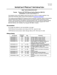
to Revision "B". These kits consist of an EPROM, floppy diskette, updated manual, and product labels. Table
1-1 lists many OIU features. An entry of "B/C" in this table indicates a Revision B feature not previously available.
Revision "C" Units
These units are nearly functionally identical to the Revision "B" units, but have significant hardware differences.
Because of these hardware differences, these units offer some features not available with Revision A or Revision
B units. An entry of "C" inTable 1-1 indicates a feature only available in a Revision C unit. An entry of "B/C" indicates
the feature is available in either Revision B or C.
1.5
Features
All Horner Electric Operator Interface Units allow direct connection to either a Series 90 PLC programming port (via
SNP protocol) or to the Genius Distributed I/O network. All OIUs have two serial ports, one for PLC or Genius
connection, and an RS-232 port for connection to a personal computer for optional software setup. All OIUs feature
an alphanumeric textual display and programmable function keys. This manual describes only the OIUs for SNP
communications. Genius OIUs are described in a different publication.
CHAPTER 1: INTRODUCTION
Operator Interfaces
Page 1-3
OIU057
OIU157
OIU177
OIU277
OIU327
OIU357
þ
þ
þ
þ
þ
þ
OIU367
Features
RS-485 Port for SNP Connection
þ
RS-232 Port for SNP Connection
þ
RS-232 Port for Programming
20 key Numeric Keypad
Programmable Function Keys
6
þ
þ
þ
þ
12
12
þ
14
þ
þ
þ
þ
þ
þ
12
12
12
þ
þ
þ
þ
þ
I/O Mapped LED's
þ
2 x 16 Liquid Crystal Display
þ
þ
2 x 20 Vacuum Fluorescent Display
þ
4 x 20 Vacuum Fluorescent Display
Character Height
Real-time Calendar Clock
Configurable with IBM Software
.375"
.375"
.197"
.197"
.44"
.44"
.44"
opt.
þ
þ
þ
þ
þ
þ
þ
þ
þ
þ
þ
þ
þ
þ
þ
þ
þ
þ
Configurable from Keypad
Alarm Enunciation Capability
þ
þ
þ
þ
þ
þ
þ
Serial Printer Support
þ
þ
þ
þ
þ
þ
RS-485
Double Integer Read/Write
þ
þ
þ
þ
þ
þ
þ
Performs Linear Scaling (mx + b)
þ
þ
þ
þ
þ
þ
þ
SNP Pass Through
C
C
C
C
C
C
C
C
C
C
Hand Held Programmer Emulation
Eight User Definable Characters
C
C
Message Chaining
B/C
B/C
B/C
B/C
B/C
B/C
B/C
Keypad Masking to Disable Indiv. Keys
B/C
B/C
B/C
B/C
B/C
B/C
B/C
þ
þ
þ
þ
þ
þ
Multi-Dropped PLC Support
Table 1-1. Feature List by Model Number.
Page 1-4
1.6
CHAPTER 1: INTRODUCTION
Model Specifications
Operator Interfaces
OIU057
OIU157
OIU177
OIU277
OIU327
OIU357
OIU367
Specifications
NEMA Rating
NEMA 4-12
Height (inches)
3.50"
5.50"
5.50"
5.50"
7.25"
7.25"
7.25"
89
140
140
140
185
185
185
6.00"
7.75"
7.75"
7.75"
11.75"
11.75"
11.75"
153
197
197
197
299
299
299
2.13"
2.13"
2.13"
2.63"
2.13"
2.13"
3.50"
54
54
54
67
54
54
89
5VDC Power Requirements (mA)
250
250
NA
NA
NA
NA
NA
24VDC Power Requirements (mA)
120*
120*
120
340
300*
300*
350*
DC Power On Current Surge (A/ms)
1/30
1/30
1.5/50
2.1/100
3/100
3/100
3/100
NA
NA
NA
NA
320
320
320
-
-
-
-
8/25
8/25
8/25
Height (millimeters)
Width (inches)
Width (millimeters)
Mounting Depth (inches)
Mounting Depth (millimeters)
85-267VAC Power Requirements (mA)
AC Power On Current Surge (A/ms)
Operating Temperature
0 to 60°C
Relative Humidity (non-condensing)
5% to 95%
NA = not available, * = optional (-24 suffix)
Table 1-2. Specifications List by Model Number.
CHAPTER 2: SCREEN UTILIZATION
Page 2-1
CHAPTER 2: SCREEN UTILIZATION
This chapter describes the concept of Horner Electric’s Operator Interface Unit Screens, and how they may be
classified and mapped for the most effective use of the OIU resources.
2.1
Concept of “Screens”
The primary function of Horner Electric Operator Interface Units is to display text and/or data which is pertinent to
the operation of the control system. This text and/or data may be used for the enunciation of machine alarms, the
adjustment of machine setpoints, the display of production statistics, etc. The OIUs may be set up with up to 250
stored screens (messages), where a screen consists of 2-lines by 16 or 20 characters, or up to 150 stored screens
(messages), where a screen consists of 4-lines by 20 characters, each containing text and/or data. The only
restrictions on screen content are:
1)
Maximum of four (4) fields displaying PLC data per screen.
2)
Maximum of 32 total characters on a 2 line x 16 character display, or a
maximum of 40 total characters on a 2 line x 20 character display, or a
maximum of 80 total characters on a 4 line x 20 character display.
Potentially, up to 1000 different PLC data registers could be monitored (250 screens x 4 data fields/screen) by a
2 line version of the OIU, the 4 line versions are limited to 600 total register (150 screens x 4 data fields/screen).
The manner in which text and/or data is placed on a screen is totally up to the user. Not all screens must contain
data. For example, screens containing machine alarm messages are very likely to be entirely textual, while
messages containing an adjustable machine setpoint would likely contain descriptive text and data.
PLC data is displayed by formatting an OIU screen to contain one or more PLC data fields. There are two types
of data fields, read-only data fields, and read-write data fields. As stated previously, an individual screen may
contain a maximum of four data fields.
When an OIU screen containing register data is being displayed, the OIU constantly reads and displays the current
value of that data from the PLC (or Genius). A read-only data field may only be monitored, its value may not be
changed by the operator. Read-only data fields are commonly used to display data fields such as temperatures,
production counts, etc., which are not to be changed by the user. A read-write data field is also constantly read
and displayed by the OIU, but the operator has the ability to change the value of the register data. Read-write data
fields are commonly used to display data fields such as machine setpoints, etc. which may be changed by the
operator.
2.2
Types of Screens
The system designer may utilize many different “types” of stored screens, that is, screens which are set up by the
designer to serve different functions. While the OIU hardware and software does not make distinctions regarding
the types of screens used, an effective system designer makes distinctions and plans carefully for the types of
screens they will use in an application. Some example types are listed in Table 2-1. The types listed in Table
2-1 are examples and are not a complete list. They are listed simply to illustrate how screens may be classified
by function, allowing the system designer to plan for a more complete application.
Page 2-2
CHAPTER 2: SCREEN UTILIZATION
Screen Type
Example Useage
Screen Access
Production Information
Production Count, Parts/Hour
From Keypad
Machine Status
Temperatures, Pressures
From Keypad
Machine Setpoints
Timer Setpoints
From Keypad
Operator Prompting
Start Motor, Start Pump
Forced by PLC
Alarm Enunciation
Motor Overload Tripped
Forced by PLC
Troubleshooting
PID Setpoints
From Keypad w/Password
Table 2-1. Example Screen Useage.
2.3
Screen Access
Another important screen characteristic listed in Table 2-1 which should be considered is screen access. Screen
access is defined as the manner in which screens are selected for display. The OIUs allow screen access (screen
selection) in four ways,
1)
selected directly from the keypad by the operator,
2)
forced for display by the screen chaining option,
3)
forced for display by the PLC, and
4)
selected from the keypad with a password.
Some screens may be accessible directly by the user from the keypad. These screens usually contain data which
is useful to the operator at various times. Therefore, these screens may be accessed directly by the operator from
the keypad whenever they need it. Some examples of screens which would be accessed directly by the user are
Production Information, Machine Status and Machine Setpoint screens.
Some applications may require a series of screens to be shown, to either display a more complex message or to
step an operator through a process. This could be done by forcing the screens with the PLC, but more simply the
screen chaining option can be set allowing a screen to automatically go to another screen after a set amount of time.
Complex messages, multiple related data screens, and process prompting are examples of the possible uses of
the screen chaining.
There are some screens which should only be displayed when the PLC forces them to be displayed. These are
typically screens which display a message stating that a current condition exists in the machine which should be
brought to the operator’s attention. Screens such as Operator Prompting and Alarm Enunciation would be examples
of this. If these screens were directly accessible by the operator, confusion could result when an alarm or prompting
message was displayed when the machine condition described by the message did not exist.
Screens used only by qualified personnel during system troubleshooting should not be available to the typical
operator. These screens can be accessed utilizing the OIUs password protection. For a detailed description of
the password protection capabilities of the OIUs, see section 2.5.
CHAPTER 2: SCREEN UTILIZATION
Page 2-3
How does the OIU distinguish which screens are accessible from the keypad and which screens are only accessible
when forced by the PLC? It does so with a parameter called“high user screen number”. This parameter defines
the highest screen number which may be accessed by the operator directly from the keypad. For instance, if the
high user screen number is set at 27, screens 0-27 are accessible directly from the keypad, and screens 28 and
higher may only be displayed when forced (or by entering a password).
The need to assign screens either above or below the high user number brings up the obvious need of planning or
“mapping” the types of screens used and in which order they will be programmed. The next section describes the
task of making a screen “map”.
2.4
Making a Screen “Map”
Because of the number of screens available (250 or 150), the number of types (functions) of screens which may be
classified by the system designer, and the two different ways in which screens may be accessed, it is recommended
that a screen “map” be laid out before setting up individual screens. Mapping is not required by the OIU, but is very
important for orderly system integration. It allows for the development and potential expansion of the Operator
Interface setup. A sample screen map is shown below in Table 2-2:
Screen
Number
Screen Type
0-3
Production Information
4-10
Machine Status
11-13
Machine Setpoints
High User Screen Number = 13
14-100
Empty (Future Expansion)
101-115
Operator Prompting
116-121
Empty (Future Expansion)
121-152
Alarm Enunciation
153-200
Empty (Future Expansion)
201-205
Troubleshooting/Critical Setpoints
206-249
Empty (Future Expansion)
Table 2-2. Sample Screen Map
The sample map shows six types of screens. The first three, Production Information, Machine Status, and Machine
Setpoints, may be accessed directly by the operator from the keypad. These are user accessible screens. The
next two screen types, Operator Prompting and Alarm Enunciation, are only displayed when the PLC forces them
to be displayed. The last type, Troubleshooting Screens, are accessed only by qualified personnel with a password.
These last three screen types are user protected screens. In the above diagram, the High User Screen Number
is shown as the highest user-accessible screen.
Typically, most applications utilize only a fraction of the OIU’s available screens. It is important when laying out
the screen map that future expansion be considered. It is a good idea to leave some empty screens between different
screen types which may be filled in the future. Note that no empty screens should be left in the user accessible
area, because the operator could potentially access a blank screen, which could confuse them into thinking that
the OIU is malfunctioning.
Page 2-4
2.5
CHAPTER 2: SCREEN UTILIZATION
Passwords
OIU models which feature full numeric keypads may be configured with passwords which can restrict OIU access
to Operators. There are two levels of password protection:
1)
A Level-1 password restricts access to screens above the High User Screen Number (such as
Troubleshooting, Critical Setpoints, etc.),
2)
A Level-2 password restricts access to the OIU Setup Mode and can also be used to access
screens above the High User Screen Number
Operators who do not have access to either of these passwords may not exit Autorun mode, nor access any screen
above the high user screen number.
2.6
Operator Interface Setup
Once the various types of screens to be utilized in an application have been established, and a screen map has
been laid out, it is time to set into motion the process of configuring OIU screens. There are two mechanisms which
may be used to set up the OIUs; the built-in Setup Menu, and the personal computer configuration software.
The configuration software is recommended for all users, because it gives them the ability to configure a number
of OIU screens in the fastest possible manner, and because it provides diskette backup for the application. This
makes it easier to program multiple units, which is critical for an Original Equipment Manufacturer (OEM).
Furthermore, units without a numeric keypad may be configured exclusively with the software.
The built-in menu (available on models with numeric keypads) is also important, because it provides a simple way
to make quick changes to the OIU setup without additional hardware (a personal computer). If available, it can be
used exclusively to set up the OIU, but it takes considerably longer to enter OIU screen text due to the limited
keyboard, and does not provide diskette backup.
CHAPTER 3: APPLICATION DEVELOPMENT
Page 3-1
CHAPTER 3: APPLICATION DEVELOPMENT
This chapter lists the available features and functions of the OIUs, and how they might be applied in an application.
It describes how the features work and how they may be used, but does not list the keystrokes necessary to set
up the unit from the keypad or programming package. It is recommended that this chapter be read to understand
the individual features available in the unit, before actually “keying in” the setup.
Multiple examples for the key features, including sample OIU configuration and PLC ladder logic illustrations, may
be found in Chapter 7, Application Examples.
3.1
Autorun and Setup Modes
The OIU has two basic modes of operation,Setup Mode andAutorun Mode. In Setup mode, the OIU is configured
from its keypad with the Setup Menu or from the personal computer configuration software. During Setup Mode,
the OIU does not communicate with the PLC, and the RS-232 port can communicate only with a personal computer
serial port for setup purposes. For units which may be configured from the keypad, the function keys have special
setup functions during Setup Mode.
The OIU is put into Autorun Mode when its screens have been configured and it is ready to be placed into service.
In Autorun Mode, the OIU communicates with the PLC, and all of its features (including function keys) are active.
In this mode, the RS-232 port may communicate with other serial devices such as printers, modems, etc.
The OIU Mode can be set by the software, or from the keypad on some units. The procedure for setting the mode
is discussed later in the manual.
3.2
Using the OIU to Display PLC Data
The ability to read and/or write PLC register data is a major function of the OIUs. “Register data” refers to any piece
of data which is contained in the PLC which can be read or written by the OIU. This includes PLC I/O (%I, %Q,
%AI, %AQ), internal PLC registers (%M, %R, %T, etc.), Global Data, etc. This data can be used for machine
setpoints, the display of production information, or other functions.
A sample OIU screen as seen from the programming software is shown below:
This screen contains two data fields. The first is a read-only data field, four characters in length, and is described
with the text, “Part Count:”. The second is a read-write data field, three characters long, and is described with the
text, “Cycle Time”. The read-only data field character is represented with a ‘block-R’, while the read-write data field
character is represented by a ‘block-W’.
When displaying this screen in Autorun Mode, the ‘block-R’ and ‘block-W’ characters will be replaced with valid
register data from the PLC. In order for the OIU to determine which data register values are to be placed on the screen,
several additional parameters must be specified for each data field during OIU setup. The register data field
information for the example screen is shown below:
Page 3-2
CHAPTER 3: APPLICATION DEVELOPMENT
The data field information parameters are summarized below:
Parameter
Read-only/Read-write
Block
Register
Description
Defines the ability of the data field to be changed by Operator
Identifies the PLC containing the data field
Lists the Series 90 Reference Type & Address
Bits
Defines the number of consecutive bits to be read
Base
Defines the form data is to be presented (decimal, hex, etc.)
Table 3-1. Data Field Defining Parameters
Each parameter is discussed in detail in the sections to follow.
3.2.1
Data Field Type
There are two types of data fields, read-only and read-write. During Autorun mode, Read-only data fields are
constantly monitored by the OIU, and their value may not be changed by the user. During Setup Mode, Read-only
data field characters are represented by a ‘block-R’. During Autorun mode Read-write data fields are constantly
monitored by the OIU, and their value may be changed by the operator from the keypad of the OIU. During Setup
Mode, Read-Write data fields are represented by a ‘block-W’.
3.2.2
Block Number
The OIUs have the ability to be used in multidrop applications, with a single OIU communicating to multiple PLCs.
In these applications, a manner must be used to identify which PLC contains the data field to be displayed. The
Block Number parameter is used for this purpose. However, most applications use a "point-to-point" architecture,
with a single OIU communicating to a single PLC. In these applications, the Block Number parameter is simply
left at its default of 0. For further details on utilizing the Block Number in multidrop applications, see Section 3-12,
"Multidrop Applications".
CHAPTER 3: APPLICATION DEVELOPMENT
3.2.3
Page 3-3
Reference Type and Address
Reference types identify the different locations where data is stored in the Series 90 PLC. These references are
1-bit or 1 word (16-bits) in length. There are a variety of reference types for the Series 90 PLCs, listed in Table 32. For a listing of the valid address ranges for the Reference Types listed below, see the GE Fanuc User’s Manual
for the Series 90 PLC used in your application.
For a detailed description of the Text Table and Floating Point bases listed in Table 3.3, see sections 3.6 and 3.7.
Reference Type
Description
Default # of Bits
%R
Register Memory
16
%AI
Analog Input
16
%AQ
Analog Output
16
%I
Discrete Input
1
%Q
Discrete Output
1
%T
Temporary Coils
1
%M
Internal Coils
1
%S
System Memory
1
%SA
System Memory
1
%SB
System Memory
1
%SC
System Memory
1
%G
Genius Global Data
1
Table 3-2. Series 90 Reference Types
3.2.4
Range
In addition to specifying single bit or word type data references, the OIU also gives users the ability to specify a
“range” of data to be read and displayed in a single OIU data field. This can be useful to display a series of consecutive
bits (up to 16) in a single data field. In most cases the system designer is interested in displaying an entire reference,
so the default range is used. The default range for a bit-type reference is 1-bit, for a byte-type reference is 8-bits,
and for word type references is 16-bits.
If a system designer is interested in displaying a series of consecutive bit-type references, or extracting a series
of bits from a word or byte type reference, specifying range can be a useful feature. For example, specifying range
allows the display of %M1-%M6 in a single data field. It also allows the display of %R1, bits 3-9 in a single data
field. Bits extracted must fall within two 8-bit boundaries. For instance, you cannot specify %M7-%M20 for a data
field because this data field resides in three 8-bit boundaries at %M1-8, %M9-16 and %M17-24.
Page 3-4
3.2.5
CHAPTER 3: APPLICATION DEVELOPMENT
Base
The OIU allows register data to shown in several different display formats, listed below:
Base
Display Range
Maximum Length
+/- Decimal
+/- 32,767
6 (5 digits plus sign)
+ Decimal
0 to 65,535
5
Hexadecimal
0000H to FFFFH
4
Binary
0 to 1111 1111 1111 1111
16
+/- Double
+/- 9,999,999
9 (8 digits plus sign)
+ Floating Point
0 to 9,999,999
9 (8 digits plus decimal point)
+/- Floating Point
+/- 9,999,999.
10 (8 digits plus decimal point and sign)
Text Table
character based
one display line
ASCII
character based
one display line
Table 3-3. Available Bases. Note that commas are not displayed in OIU data fields.
3.3
Function Keys
Another key feature of the OIUs are the ability to utilize function keys. The function keys are clear in color, and can
accept a customized template. The template inserted in the factory is yellow in color, with F1, F2, F3, etc. labelled
on the front. Units which support keypad configuration have setup functions printed on the rear of the function key
template. Function keys can be used by system designers in two different ways:
1)
Function keys may be mapped into I/O so that they emulate non-critical momentary pushbuttons,
2)
Function keys may be used as a “macro” to perform functions with a single keystroke that would
normally take many keystrokes.
A function key can perform each of these two capabilities simultaneously, if desired. In most applications, function
keys are used as momentary pushbuttons. They are mapped directly into the PLC or Genius as I/O, so they can
perform any non-safety related function that a momentary pushbutton would perform. Function keys are not to
be used to perform safety related functions such as emergency stops. These functions should be
performed by hard-wired pushbuttons wired to industrial safety standards. In other applications, function
key macros are used to automate functions which normally take many keystrokes. Examples of this are to select
a particular screen for display, to enter a value for a PLC data register, etc.
3.3.1
Function Keys as Momentary Pushbuttons
To map the function keys into PLC I/O as a pushbutton, the function key register must be set. The function key
register is a register in the PLC which is constantly updated by the OIU with the status of the function keys and/
or other keys on the OIU keypad.
CHAPTER 3: APPLICATION DEVELOPMENT
Page 3-5
If the function key register is assigned a bit type reference (%M, %T, etc.), the user may monitor the status of up
to 16 keys. If the function key is assigned a word-type reference (%R, etc.), the user may monitor the status of
up to 32 keys on the OIU keypad. The order in which those keys are assigned is illustrated in Table 3-4.
Keypad Type
A
B/D
C
Bit
#
Key
Bit Type
Sample
Addres
Word
Type
Sample
Address
Keypad Type
A
B/D
C
Bit
#
Bit Type
Sample
Addres
Word
Type
Sample
Address
Key
F1
F1
F1
1
%M1
%R5, bit 1
1
17
not avail.
%R6, bit 1
F2
F2
F2
2
%M2
%R5, bit 2
2
18
not avail.
%R6, bit 2
F3
F3
F3
3
%M3
%R5, bit 3
3
19
not avail.
%R6, bit 3
F4
F4
F4
4
%M4
%R5, bit 4
4
20
not avail.
%R6, bit 4
F5
F5
F5
5
%M5
%R5, bit 5
5
21
not avail.
%R6, bit 5
F6
F6
F6
6
%M6
%R5, bit 6
6
22
not avail.
%R6, bit 6
UP
F7
F7
7
%M7
%R5, bit 7
7
23
not avail.
%R6, bit 7
DOWN
F8
F8
8
%M8
%R5, bit 8
8
24
not avail.
%R6, bit 8
F9
F9
9
%M9
%R5, bit 9
9
25
not avail.
%R6, bit 9
F10
F10
10
%M10
%R5, bit 10
0
26
not avail.
%R6, bit 10
F11
F11
11
%M11
%R5, bit 11
dec pt.
27
not avail.
%R6, bit 11
F12
F12
12
%M12
%R5, bit 12
D/H/B
28
not avail.
%R6, bit 12
SHIFT
F13
13
%M13
%R5, bit 13
UP
UP
29
not avail.
%R6, bit 13
CLEAR
F14
14
%M14
%R5, bit 14
DOWN
DOWN
30
not avail.
%R6, bit 14
MODE
15
%M15
%R5, bit 15
RIGHT
RIGHT
31
not avail.
%R6, bit 15
ENTER
16
%M16
%R5, bit 16
LEFT
LEFT
32
not avail.
%R6, bit 16
Table 3-4. Function Keys (and remaining keys) mappable into PLC memory.
Page 3-6
3.3.2
CHAPTER 3: APPLICATION DEVELOPMENT
Function Keys as Macros
When using a function key as a macro, it can perform any function that could be performed by the operator from
the keypad in Autorun mode, but in a single keystroke. These functions include changing screens, setting a register
to a new value, etc. The operations or keystrokes available for function key macros are listed below:
For example, in an application, screen #13 contains a key machine setpoint. The system designer wants to set
up a function key which displays screen #13 when pressed. To accomplish this using a function key macro, it is
helpful to first determine the sequence of keystrokes which the operator would have to execute in order to change
to screen #13 manually. Provided that the screen is accessible and non-password protected, the proper key
sequence to change to screen #13 in Autorun mode is as follows:
When configuring this key sequence from the keypad (some units only), the exact key sequence is simply entered
for the function key. When setting this function key sequence with the OIU configuration software, the following key
sequence would be configured:
When a screen is displayed as a result of a function key macro, or when being triggered by the PLC, no passwords
are prompted, even if the displayed screen is above the high user screen number.
Another commonly used function key macro would perform the function of setting a data register in the PLC to a
particular data value. When performing this function manually during Autorun mode, the operator would perform the
following steps:
1)
2)
3)
4)
Change to the screen containing the data,
select the data field to be changed,
enter the new value, and
return to the screen previously displayed.
The first three steps of the key sequence may be programmed rather easily. For instance, suppose the first read/
write data field on screen #37 is to be set to a decimal value of 100. The first part of the key sequence follows:
* This sequence will bypass the level 1 password
CHAPTER 3: APPLICATION DEVELOPMENT
Page 3-7
The difficulty arises when trying to program in step 4 of the sequence, "return to the previous screen". This is a
problem because the operator could be on one of any number of screens when he presses the function key. When
programming a function key sequence from the keypad (some units only) a special key combination performs the
"return to previous screen" function. This key sequence is as follows:
Whenever this key combination is placed at the end of a function key macro, the current screen active when the
function key is pressed by the operator is the screen displayed at the completion of the sequence. During this
operation the OIU will display "Executing Function Key...".
Configuring this function key sequence from the OIU software is much more intuitive. The function key sequence
as configured by the OIU software is below:
The above sequence selects screen #100, selects the first data field for editing, enters a value of 100, and reverts
to the original screen.
3.3.3
Function Keys Used for PLC Data Editing
OIUs which do not contain numeric keypads do not contain the RIGHT ARROW or ENTER key. Therefore, the
manner in which PLC data is modified by the operator is different. The final function key is programmed by default
as a "Modify / Fast" key (F6 for the OIU057 and F14 for the OIU277). The operator presses this key to select the
PLC data field among the read/write data fields displayed on the current screen. The operator then uses the UP
and DOWN arrow keys to increment / decrement the data. He may also press the "Modify / Fast" key with an arrow
key to change the data value rapidly. For complete details on the operation of these keys in Autorun Mode, see
Chapter 6.
If an application does not intend to change PLC data fields, the final function key may be overwritten with a macro
function. Figure 3-1 shows the function key configuration screen for an OIU057, showing F6 configured as the
"Modify / Fast" key by default.
Page 3-8
CHAPTER 3: APPLICATION DEVELOPMENT
Figure 3-1. OIU057 Function Key screen showing F6 defaulting to "Modify / Fast" functionality.
3.4
Controlling Screen Selection with the Trigger Register
As stated in the Screen Management chapter, there are two ways in which screen selection can be accomplished:
1)
The Operator may select a user accessible OIU screen from the keypad, or
2)
The PLC may force the display of any OIU screen using the Trigger Register.
The trigger register is a data register in the PLC which is constantly monitored by the OIU. The numerical value
of the trigger register either forces display of an OIU screen, or allows the Operator to select a screen from the
keypad. If the value of the trigger register is between 0 and 249 inclusive, the screen number corresponding to the
trigger register value will be forced for display. If the value of the trigger register is 250 or higher, the operator may
select which screen below the high user screen number is to be displayed from the keypad.
This feature is critical for alarm enunciation applications, or applications in which a “menu” system is set up to lead
the Operator through a series of data entry screens. The trigger register is an optional parameter, and if unused
the operator will have control of screen selection at all times.
The screen status register is a data register in the PLC which the OIU updates with the current screen number
whenever a change has occurred. This can be useful for detecting when the Operator enters or leaves a particular
screen on the OIU, for those periods of time when the trigger register has relinquished screen control to the operator.
For examples utilizing the trigger register and/or screen status register, refer to the application examples section
of the manual.
CHAPTER 3: APPLICATION DEVELOPMENT
3.5
Page 3-9
Print Register & Print Status Register
In addition to forcing the display of a particular screen, the PLC can also force the printing of screen(s) through its
RS-232 port (the RS-485 port on the OIU367) to a serial printer using theprint register. Text, embedded data, and
printer control characters (carriage return, line feed, and form feed) can be passed to the printer, allowing for a very
versatile printer interface.
When utilized, the print register is constantly monitored by the OIU. When the value of the print register changes
to a legal screen number, the text, data and/or printer control codes contained on that screen are printed out the
printer port. The print status register is then updated with the number of the last screen which was printed, and no
additional screens are printed until the value of the print register changes to another legal screen number.
For examples utilizing the print register and/or print status register, refer to the applications examples section of
the manual.
3.6
Text Tables
Text Tables are a feature of the OIU which can be very useful in the description of machine operation. Text Tables
are a special base which allow text strings stored in the OIU to be displayed instead of numerical data when
monitoring PLC register data. For example, say Machine “A” has three modes of operation, “Off”, “Hand”, and “Auto”.
In the PLC, these modes are represented by values of 0, 1 and 2 respectively in data register %R1. If the PLC data
is shown numerically on the OIU screen, in Autorun mode the "Machine Mode" screen would look like the following:
or
or
Using the Text Table feature, a Text Table can be set up so that PLC register values 0, 1 and 2 correspond to the
text strings “OFF”, “HAND”, and “AUTOMATIC”. The Text Table setup, as seen on the configuration software, is
shown below:
Page 3-10
CHAPTER 3: APPLICATION DEVELOPMENT
As a result of this text-to-numeric correlation, the "Machine Mode" screen displaying data utilizing the text table
base would look like this:
or
or
It is obvious that the above textual representation of the current machine mode is much clearer to the operator than
the numeric representation. For detailed instructions on setting up text tables, see Chapters 4 and/or 5.
3.7
Floating Point Values
Another convenient OIU feature is the ability to display floating point data. This performs two main functions:
1)
Allows users to monitor and enter data which contains a decimal point.
2)
Allows data stored in the PLC as an integer value to be scaled to engineering units and displayed
on the OIU.
The OIU performs these two functions by performing linear scaling on the PLC integer data. This scaling is
represented with the following formula:
y = mx + b
where x is the integer value stored in the PLC,
y is the floating point value shown on the display,
m is the slope (multiplier), and
b is the offset (adder).
CHAPTER 3: APPLICATION DEVELOPMENT
Page 3-11
The math package used in the OIU is capable of 8 digits of accuracy. When displaying a floating point data field
in Autorun mode, the OIU reads the integer value of the register from the PLC, scales it, and displays it in floating
point format. If the operator wishes to change the value of the floating point data field, he enters it in floating point
format, and the OIU performs the scaling in reverse, writing the appropriate integer value to the PLC data register.
For instance, let's say that a system designer wishes to display a decimal data value between 0.0 and 99.9 on the
OIU screen. This data is stored in PLC register %R13 as an integer value between 0 to 999. In order to display
the data on the screen with the decimal point, he must set up a data field on the OIU which is 4 characters long
(3 digits plus the decimal point) and uses the floating point base. The screen and data field information table as
seen on the configuration software would look like the following:
The system designer must now set configure the floating point data parameters (in this case, parameter set number
1) to scale the data from 0-999 to 0.0 - 99.9. In this case, the floating point parameter set number 1 would be equal
to a slope m of 0.1 (multiply by 0.1) and an offset b of 0 (add 0). The number of digits to the right of the decimal point
must also be configured in the floating point parameters, and in this case that would be 1.
When the above screen is selected in Autorun mode, if %R13 contains an integer value of 357, for instance, the data
will be displayed as follows:
If the operator wishes to change the value to 42.2, he may enter the data with the decimal point, and the OIU will perform
the scaling in reverse and write a value of 422 to %R13.
For more complex examples of scaling PLC integer data values to engineering units and displaying them on the OIU,
see the applications examples section of the manual.
Page 3-12
3.8
CHAPTER 3: APPLICATION DEVELOPMENT
Calendar Clock
The OIUs (except the OIU057) come standard with a built-in calendar clock. This feature is useful when used on
PLCs such as the 90-20, 90-30 CPU 311, etc. which do not have a built in clock. When enabled, the OIU downloads
six registers of time/date information to the PLC at a programmable interval. The content of the six registers, and
the available update intervals are listed in the tables below. The time/date data is downloaded to the PLC in BCD
format, matching the format used by the Series 90 PLCs which do incorporate a built-in clock of their own (90-30
CPU 331, 90-70, etc.)
Word #
Data Stored
Data Range
Data Type
1
Hour
0-23
BCD
2
Minute
0-59
BCD
3
Day of Week
1-7
BCD
4
Month
1-12
BCD
5
Date
1-31
BCD
6
Year
1990-2089
BCD
Table 3-7. Calendar Clock data format.
Interval
At power-up
Once per Minute
Once per Hour
Once per Day
Table 3-8. Available Calendar Clock update intervals.
3.9
The LED Register
This feature is available only on some units, such as the OIU357 and OIU367. These OIU models feature 12 LEDs
located on the function keys which can be used as indicating lights. The OIU continually monitors a register in the
PLC, and the LEDs are lit according to the value of that register. This register is known as the LED register. If
the LED register is a 1-bit data reference (%M, etc.), 12 consecutive references should be specified. If the LED
register is a 16-bit data reference (%R, etc.), the LEDs reflect the status of the 12 least significant bits of the
reference.
3.10
The Expansion Register
The expansion register feature is available only on OIU models which are equipped with an expansion slot, such
as the OIU367. This expansion slot can be filled with custom developed add-on boards for high volume OEMs. The
interface to the add-on board is a multiple register interface. Those OEMs who have a special need for the additional
functionality that this board can provide (communications, etc.) contact Horner Electric to discuss the possibility
of custom development.
CHAPTER 3: APPLICATION DEVELOPMENT
3.11
Page 3-13
The Keypad Mask
This feature can prevent the operator from performing undesired keystrokes, or can be used to essentially "re-map"
some of the keys on the keypad. This feature is very useful when using one of the OIUs with a numeric keypad.
For example, using the masking feature, the system designer can prevent the "Change to Mode #:" message from
being displayed when the operator presses the MODE key. If the keypad is mapped to PLC I/O, the keystroke is
still seen by the PLC, but the OIU ignores it.
The keypad mask register is constantly monitored by the OIU. If the mask is mapped to a bit-type PLC reference,
up to 16 keys may be masked. If a word-type reference is used, up to 32 keys may be masked. Each bit of the
keypad mask register corresponds to a particular key on the keypad (See Table 3-4 for the proper mapping order).
If the bit is "1", than the corresponding key is "masked". If the bit is "0", the corresponding key is not masked.
3.12
Multidrop Applications
SNP or SNPX Protocol
The OIUs support two distinct Series 90 Protocols. "SNP" protocol is designed primarily for point-to-point
applications -- where a host (in this case, a OIU) communicates with a single PLC. A characteristic of the protocol
is a long "attach" sequence, which may take several seconds to complete. This attach sequence must be performed
every time communications is initiated with a particular PLC. For this reason, SNP is not recommended for OIU
multidrop applications, because of the long delay required to switch communications from one PLC to another. After
attaching, SNP performance exceeds SNPX performance.
SNPX protocol has been developed with multidrop data acquisition in mind. The SNPX messages contain little
overhead, but do include a PLC address in every message. There is no "attach" sequence, and no appreciable delay
when communications is switched from PLC to PLC. Therefore, for an OIU multidrop application to be successful,
SNPX protocol must be utilized. This is set via a configuration parameter on the "CPU Address" menu, discussed
below.
SNPX Multi-Drop using the PLC ID Table
Series 90 multi-drop applications utilize the PLC ID to uniquely identify each PLC. The PLC ID is a one-to-eight
character identifier assigned to a Series 90 CPU during LogicmasterTM 90 configuration (For more information
regarding this ID, see your GE Fanuc Series 90 and Logicmaster 90 documentation). The OIU contains a table that
can be configured by the system designer during Setup Mode which lists the PLC IDs present on the network. This
PLC ID table contains 32 entries, numbered Block 0 to Block 31. Each Block number has a corresponding PLC
ID assigned to it. In a multi-drop application, one Block number would be configured with a PLC ID for each multidropped PLC, and the remainder would be left blank (see the example configuration screen that follows).
Page 3-14
CHAPTER 3: APPLICATION DEVELOPMENT
For instance, in an application with three PLCs connected to a single OIU, three block numbers in the PLC ID table
would be configured with PLC IDs, and the remainder would be left blank. All data fields accessed by an OIU in
a multi-drop application must reference a block number which has been configured with a PLC ID. Referencing
a block number with an empty PLC ID in a multi-drop application will not allow communications between
the OIU and any PLC!
A sample PLC ID table is shown above. A total of three block numbers have been configured, for PLC IDs “A1”,
“B0007”, and “F32911”. To read/write data to PLC “A1”, the OIU data field must specify Block 00 in the data field
parameter. To read/write data to PLC “F32911”, Block 02 should be specified, etc.
3.13
SNP Optimization
Any serial device communicating with a PLC causes an increase in PLC scan time. While the Horner Electric OIUs
do have this effect as well, they also may be configured to minimize this effect. "SNP Optimization" is an OIU feature
which allows the system designer to select between an optimal PLC scan, or optimal OIU update time. If SNP
optimization is set toOIU (the default), the update time of PLC data monitored by the OIU is at its minimum. However,
the effect of the OIU communications on the PLC scan time is at its maximum. If SNP optimization is set to PLC,
the PLC scan time is at its minimum, with a somewhat slower OIU update time. The SNP Optimization feature is
set on the "CPU address" menu (see the example screen that follows on the next page). Optimization is not available
for the SNPX protocol.
CHAPTER 3: APPLICATION DEVELOPMENT
Page 3-15
Figure 3-2. CPU Address Menu, containing the "SNP Mode" and the "Optimize for OIU/PLC" Configuration
options
3.14
Serial Pass Through
This feature, present only on OIU Revision C or later, allows other serial devices to share the PLC programming port
with the OIU. This can be used to add another communications connection to a CPU311, which cannot support
the CMM Communicaitons Module. A serial device can be connected to the RS-232 port of the OIU. When this
serial device wishes to communicate with the PLC, it asserts its RTS (or carrier detect) handshaking line, causing
the OIU to monitor the RS-232 port. When the OIU detects an SNP protocol message at the RS-232 port, it passes
the message through the OIU RS-485 port to the PLC. While this message is being passed through, the OIU is
not communicating with the PLC. The serial device and the OIU cannot communicate with the PLC simultaneously.
This feature is best used for applications where occassional communications through the RS-232 port is desired,
such as a modem application.
3.15
Definable Characters
OIUs which feature the 2 line x 16 character display, such as the OIU057 and OIU157, have the ability to store up
to 8 custom characters. These custom characters are definable with the OIU software, and each consist of a 5 x
7 dot matrix, with a 5 dot "underline" area below. This feature is most effective when defining foreign characters,
or a special logo or symbol. Sets of 8 characters can be stored to disk as "libraries". This can be useful for defining
different libraries for various foreign languages, etc. See Chapter 5 for more information.
Page 3-16
CHAPTER 3: APPLICATION DEVELOPMENT
CHAPTER 4: THE KEYPAD SETUP MENU
CHAPTER 4:
Page 4-1
THE KEYPAD SETUP MENU
This chapter describes, step by step, the operation of the OIU from its built-in Setup Menu. The purpose of this
chapter is to describe to the system designer the necessary keystrokes used to perform various functions from this
menu. For a greater understanding of the function or purpose of the OIU features, see Chapter 3, "Application
Development". OIU models without a numeric keypad do not support the setup menu. These units may only
be setup from the OIU configuration software.
4.1
Menu Selections
The Setup Menu consists of a number of selections in a single list. Each "selection" is the name of a different
configuration screen. Using these configuration screens, the system designer has the capability to completely
configure the OIU without additional software or hardware. Normally, however, the Setup Menu is used to make minor
modifications to the OIU setup as opposed to creating the application from scratch.
The available menu choices are listed below:
> Access PLC Data
Cfg Screens
Cfg Text Tables
Cfg Func Key
Cfg Float Scale
Cfg High Screen
Cfg Passwords
Cfg LED Reg
Cfg Expansion Reg
Cfg Trigger Reg
Cfg CPU Address
Cfg Com Port
Cfg Prn Port
Adjust Display
Set Clock
Enter AUTORUN
Hand-held prg
Run Self Test
4.2
* The available menu choices
differ on some units. For
example, the OIU277 does not
support the hand held
programmer menu selection
Key Assignments
During Setup Mode, several keys on the OIU keypad serve different functions than their Autorun functions. These
are summarized below:
and
While on the Setup Menu, the up and down arrow keys are used
to move the menu pointer to the desired menu item.
Page 4-2
CHAPTER 4: THE KEYPAD SETUP MENU
When the menu pointer is pointing at the desired menu item, pressing the ENTER
key causes the display to switch to the configuration screen for the selected item.
The Mode key allows the user to return to the Setup Menu from a configuration screen.
4.3
Access PLC Data
This first selection on the Setup Menu does not perform a configuration function. The "Access PLC Data" screen
allows the OIU to display PLC data in a manner which is similar to the Series 90-30 Hand Held Programmer's "Data
Access" Mode. This can be useful for qualified engineers or technicians to access any of the Series 90 data table
during system setup, troubleshooting, etc.
After selecting the Access PLC Data menu item, the screen appears as follows:
Enter Data Type:
00 %R
The “00” shown on the display is a “block number” which identifies the PLC to be accessed. In a typical point-topoint application, it is always 00. Next to the Block Number is the Reference Type. There are many different data
reference types available with the Series 90 and Genius. For a complete list, see Tables 3-2 and 3-3 in Chapter 3.
Pressing the LEFT and RIGHT arrow keys increments/decrements the Block Number. The UP and DOWN arrows
toggle through the available reference types (%R, %AI, %I, %M, etc). Once the desired block number and reference
type are displayed, the data address may be keyed in numerically, followed by ENTER. The OIU will then display
the current value of the data register selected. Pressing the DEC-HEX-BIN key toggles the base of the displayed
data between decimal, hexadecimal, and binary. Pressing the RIGHT arrow key allows the data value to be changed.
After pressing the RIGHT arrow key, the data value begins to flash. The new data value may then be keyed in, followed
by ENTER. If the PLC program does not contain ladder logic overwriting the data value, the data value will be changed
successfully by the OIU. To select another reference to display, press the MODE key. To return to the Setup Menu,
press MODE a second time.
4.4
Cfg Screens (Configure Screens)
Even though most users use the personal computer configuration software to set up the OIU, it still is possible to
set up the OIU completely from the keypad, if desired. This ability is most useful for making minor changes after
the unit has been installed. While configuring screens from the keypad, it is recommended that the function key insert
be flipped over to reveal the function keys' screen setup functions.
After selecting the Cfg Screens menu item, the user is prompted with the following display:
Enter Display
(0 to 249): 0
To set up screens (displays) from the keypad, the system designer keys in the screen number to be created or edited,
followed by ENTER. The screen then appears to go “blank” with a underlining cursor in the first position on the top
line.
_
CHAPTER 4: THE KEYPAD SETUP MENU
Page 4-3
The descriptive text and/or data fields may now be entered. The cursor keys (UP, DOWN, RIGHT, and LEFT arrows)
may be used to move the cursor. To place alphabetic text, the 1-9 keys are used. Each number key (except 0),
has 2 or 3 letters associated with it, similar to a telephone keypad. Pressing the key once will cause the first
alphabetic character to be displayed, a second time toggles to the next alphabetic character, a third time toggles
the next character, and a fourth toggles to the number itself. For instance, to display the letter L, the 5 key must
be pressed 3 times. To display the number 9, the 9 key must be pressed 4 times.
If the next character to be setup is on a different key than the current character, pressing that different key will cause
the cursor to automatically move over one position to the right. For example, “A”, “T”, “X”, and “S” are all on different
keys. If the next character is on the same key as the current character, the right arrow must be used to move over
one position to the right before entering the next character. For example, “A”, “B”, and “C” are all on the same key.
Figure 4-1. Function Key Configuration Template(s) for OIU157, OIU177 (left),
and OIU327, OIU357, OIU367 (right).
To place PLC data fields on the screen (maximum of 4/screen), Function Keys 1 (F1) and 2 (F2) are used. F1 places
a read-only data field character on the screen, and F2 places a read-write data field character on the screen. A
"flashing R" (read-only) or "flashing W" (read-write) character will be placed at the cursor position. The length of a
data field is defined by the number of adjacent “flashing R” (read-only) or “flashing W” (read-write) characters placed
on the screen. The necessary length is determined by the possible range of values, and the base which the data
is displayed in (see Chapter 3 for more details). An example screen with one read/write data field 5 characters long
is shown below:
Tank Pressure
WWWWW PSI
Page 4-4
CHAPTER 4: THE KEYPAD SETUP MENU
After placing descriptive text and/or data fields on the screen, pressing the ENTER key will cause the OIU to
automatically prompt the user for the block number, data reference, and address of the data to be read or written.
Pressing the LEFT and RIGHT arrow keys increments or decrements the block number. Pressing the UP and DOWN
arrow keys toggles between the available reference types (%M, %R, etc.). After displaying the desired reference
type, the address may be keyed in numerically, followed by ENTER. The OIU will now prompt the user for the base
of the data field. Pressing the UP and DOWN arrow keys toggles between the available choices (+/- decimal, hex,
binary, etc.). After displaying the desired base, press the ENTER key. If text table or floating point scale has been
selected the user will be prompted to enter the table number. If more than one data field exists on a screen, the OIU
will continue to prompt the user until all data fields are defined. Note that data fields are numbered 1 to 4 as they
are placed on the screen from left to right, and top to bottom.
4.5
Cfg Text Tables
Text tables are a special feature which provide a mechanism by which numerical data in the PLC may be displayed
in the form of descriptive text on the OIU.
To set up a text table, select the Cfg Text Tables menu item.
Select txt table
number: ???
Text tables may be given any number from 0 to 255. However only 256 total elements may be defined. Key in the
text table number to be defined, and press ENTER. For text table 1, the display will look like this:
Tb: 1 V1:
0
Tb: indicates the text table number. Vl: indicates the numerical PLC data value which is to be tied to a text string.
The initial value displayed is 0, and the 0 is flashing to indicate that the numerical value is ready to be entered. As
an example, we will set up a text table which will correspond three numerical values 0,1, and 2 to the text strings
"OFF", "HAND", and "AUTOMATIC", respectively. For this example 0 is the first entry, and corresponds to "OFF".
Pressing ENTER causes "0" to be accepted as the initial data value, and moves the cursor to the first position on
the bottom line. The alphanumeric string may now be keyed in by using the same keying method used for entering
alphabetic text when defining strings. To key in “OFF”, press the “6” key three times, the “3” key three times, the
right arrow, and then the “3” key three more times.
Tb: 1 Vl:
OFF
0
Pressing ENTER completes the table entry for numeric value 0. The number in the Vl: column now flashes again.
A new numeric value may be entered for this text table. In our example, that would be a “1”. After setting Vl: to a
1, the cursor now moves back down to the text line, where HAND may be entered (“4” key twice, “2” key once, “6”
key twice, “3” key once, followed by ENTER). All numeric and textual contents of a text table may be entered in this
CHAPTER 4: THE KEYPAD SETUP MENU
Page 4-5
fashion. If a new text table is created (Forward, Reverse, for example), pressing the MODE key when all entries for
the current table is complete will allow you to select another text table. Pressing the MODE key a second time will
return you to the main menu.
4.6
Cfg Func Key
After selecting the Cfg Func Key menu item, the user is prompted to enter the function key register.
Select Func Reg
00%R
The register is specified in the same manner as all other PLC data references, with the LEFT and RIGHT arrow keys
selecting the Block Number, UP and DOWN arrow keys selecting the reference type, and the numeric keys used
to enter the register address. A function key register is not required to be defined. Pressing ENTER when prompted
for the function key register without entering a register number disables the function key register. The CLEAR key
is used to clear out the function key register once one is defined.
Press the Func
Key to Define
After entering (or not entering) the data register, the OIU prompts the user to “press the function key to define”. This
is to enable the user to configure the function keys with “macro” functions. Macros are typically used to configure
function keys to change to a particular screen, set a PLC data register to a particular value, etc. In many applications,
the function keys are simply used as momentary pushbuttons, and no macro functions are to be performed by the
function keys. If no function keys are to be programmed with macros, pressing ENTER at the prompt returns to the
setup menu.
If function key macros are to be defined, the first step is to record on paper the sequence of keystrokes which will
be stored in the function key (see Chapter 3). After the keystroke sequence has been established, press the key
to define, as prompted by the OIU display. To configure F1 with a macro, press the F1 key. The display will change
to the following:
Define Func F1
The top line identifies the function key being defined, in this case F1, and the bottom line is where the key sequence
is entered. To enter the sequence, simply press the keys to be included in the sequence in the proper order. To
include the “>” and “<“ keys, shift must first be pressed. When the sequence is complete, press the function key
being defined to complete the process.
When editing a function key sequence, the left and right cursor keys may be used to navigate through the key
sequence. To delete a key from the sequence, use the left and/or right cursor keys until the key to be deleted is
flashing. Pressing the DEL (0) key while holding the SHIFT key will delete the key from the sequence. To insert a
key into a sequence, position the cursor, then press the INS (.) key while holding the SHIFT key. The message on
the screen will change from "Define Func F1" to "Insert Func F1". After the key or keys have been inserted into the
sequence, pressing the SHIFT and INS keys again changes the OIU back into overwrite mode from insert mode.
Page 4-6
4.7
CHAPTER 4: THE KEYPAD SETUP MENU
Cfg Float Scale
The purpose of the floating point scaling parameters are discussed in detail in Chapter 3. Up to 200 different sets
of floating point parameters may be setup and stored in the OIU memory. These parameters consist of slope
(multiplier), offset (adder), and number of fractional decimal places displayed. After selecting the "Cfg Float Scale"
menu item, the OIU display shows the following screen:
0
F=0
m= 1
b= 0
The flashing 0 on the screen indicates that the displayed floating point data values are for set 0. The lower-case m
indicates the slope, lower case b indicates the offset, and upper case F indicates the number of digits to the right
of the decimal point. The values of m, and b may be positive or negative, integer or fractional. The number of digits
to the right of the decimal place must be a positive integer between 0 and 7, inclusive.
To set the values, first key in the floating point scale set number (0-199) followed by ENTER. The value for the slope
m will begin to flash. Press the CLEAR key to clear the default value of 1, and then key in the value for m. To key
in a negative value, press the - key while holding in the SHIFT key. After keying in the value, press ENTER. The
data value for b will now flash. Press the CLEAR key to clear the default value of 0, and then key in the value followed
by ENTER. The value for F (the number of digits to the right of the decimal point) will flash. Pressing CLEAR clears
out the old value, and keying in the value followed by ENTER sets the number of digits to the right of the decimal point.
At this point, another floating point data set may be configured, or pressing the MODE key will return to the main
menu.
4.8
CFG High Screen
The concept of the high user screen number is discussed in Chapter 2. To set the high user screen number, select
the "Cfg High Screen" menu item. The display will display the following text:
Enter High User
Screen :
249
Pressing the CLEAR key clears the default value of 249, allowing the new value to be entered. This is entered by
keying in the screen number, followed by ENTER. Pressing the MODE key returns to the main menu.
4.9
Configure Passwords
The functionality of "Level 1" and "Level 2" passwords are discussed in Chapter 2. These passwords may be set by
selecting the "Cfg Passwords" menu item. When no passwords exist, the user will be prompted with the following
display:
New Lvl 1 Password?
CHAPTER 4: THE KEYPAD SETUP MENU
Page 4-7
The Level 1 password is entered by keying in the password, followed by ENTER. Valid password characters are 09,. The password may be up to 1 display line (16 or 20 characters) long. After entering the Level 1 password, the
OIU prompts the user to enter the Level 2 password. After entering the Level 2 password, the OIU automatically returns
to the main menu.
To change a password, the user is first prompted to enter the old password, before the new password is entered. In
this case, the OIU displays the following message:
Old Lvl 1 Password?
To clear a password, first enter the old password, and then simply press ENTER when prompted for the new password.
4.10
Cfg LED Reg
The LED register is only available on certain OIU models such as the OIU357 and OIU367. It is explained in Chapter
3. After selecting the Cfg LED Reg menu item, the display is shown as follows:
Select LED Register?
00%R
Pressing the LEFT and RIGHT arrow keys increments/decrements the block number from 00-31. Pressing the UP
and DOWN arrows allows the different reference types (%R, AI, %M, etc.) to be selected. After the desired block
number and data reference type are displayed, the register number may be keyed in, followed by ENTER. After
entering the LED register, the OIU will automatically return to the main menu.
4.11
Cfg Trigger Reg
The "Cfg Trigger Register" menu item allows the trigger register and screen status register to be configured. The
function of these registers are described in detail in Chapter 3. After selecting the "Cfg Trigger Reg" menu item, the
display shows the following text:
Select Trig Reg
00%R
Pressing the LEFT and RIGHT arrow keys increments/decrements the block number from 00-31. Pressing the UP
and DOWN arrows allows the different reference types (%R, AI, %M, etc.) to be selected. After the desired block
number and data reference type are displayed, the register number may be keyed in, followed by ENTER.
After entering the trigger register, the OIU will prompt the user to enter the screen status register. If the user does
not wish to utilize the trigger register or screen status register, he may simply press ENTER without entering a register
number. If a screen status register is to be utilized, the register may be entered in the same fashion as the trigger
register. The OIU will return automatically to the main menu after configuration of the trigger and screen status
regsiters.
Page 4-8
4.12
CHAPTER 4: THE KEYPAD SETUP MENU
Cfg CPU Address
As described in Chapter 3, the OIU maintains a table of CPU IDs which allow it to be used in Series 90 multi-drop
applications, or in point-to-point applications where a PLC ID is specified in the Series 90 CPU. For a typical Series
90 point-to-point application where no PLC ID is specified in the CPU, this feature is not used, and BLK 00 is used
in all data references.
After selecting the "Cfg CPU Address" menu item, the following screen is displayed:
CPU ID - BLK 00
Pressing the UP and DOWN arrow keys select the block number to be configured. After selecting the block number,
the CPU ID may be entered. The CPU ID is a 1 to 8 character text string which may include the characters 0-9, and
A-F. To enter the characters A through F from the keypad use F1 through F6. After configuring the PLC ID for a
particular block number, the UP and/or DOWN arows may be used to select another block number. After the last
block number to be configured has been set up with a PLC ID, pressing the ENTER key returns the display to the
main menu.
4.13
Cfg Com Port
The "Cfg Com Port" menu item allows the user to set the communications parameters for the RS-422 port which
communicates to the Series 90 PLC.
>Baud Rate:19200
Parity:
Odd
Data Bits:
8
Stop Bits:
1
Handshake: None
Pressing the UP and DOWN arrows allows for the selection of the parameter to be changed. Pressing the RIGHT
and LEFT arrow keys toggles through the available options, and pressing ENTER when the desired option is selected
causes that parameter to be stored. Pressing the MODE key returns to the main menu.
4.14
Cfg Prn Port
The "Cfg Prn Port" option allows the registers and communications rates associated with printing to be set in the
OIU. After selecting the menu item, the display shows the following:
Select Print Reg
00%R
Pressing the LEFT and RIGHT arrow keys increments/decrements the block number from 00-31. Pressing the UP
and DOWN arrows allows the different reference types (%R, AI, %M, etc.) to be selected. After the desired block
number and data reference type are displayed, the register number may be keyed in, followed by ENTER.
CHAPTER 4: THE KEYPAD SETUP MENU
Page 4-9
The OIU then prompts the user to enter the Print Status Register, which may be set in the same fashion as the print
register. After entering the print status register, the communications parameters for the port may be set. These
parameters only set the ports communications rate during Autorun mode, when connected to a printer. When
connected to a computer during setup mode, the communications rate is fixed to match that of the configuration
software. The communications parameters are as follows:
>Baud Rate:19200
Parity:
Odd
Data Bits:
8
Stop Bits:
1
Handshake: None
Pressing the UP and DOWN arrows allows for the selection of the parameter to be changed. Pressing the RIGHT
and LEFT arrow keys toggles through the available options, and pressing ENTER when the desired option is selected
causes that parameter to be stored. Pressing the MODE key returns to the main menu.
4.15
Adjust Display
This menu item allows the contrast of the display to be adjusted. Pressing the UP arrow increases intensity, and
the DOWN arrow decreases intensity.
4.16
Set Clock
This menu item allows for the configuration of the built-in calendar clock feature (optional on the OIU057). This is
an important feature in Series 90 PLCs which do not feature a clock of their own (Series 90-20, Series 90-30 CPU311,
CPU313, CPU323).
After selecting this item, the current time and date are displayed.
MON MAY 17,1994
14:43:46
The month, date, year, hours, minutes, and seconds parameters are all changeable. The day of the week is
automatically set by the OIU according to the date.
Pressing the RIGHT and LEFT arrow keys allow the date, year, hour, minute, and second parameters to be selected.
Pressing the UP and DOWN arrow keys allow the value to be incremented or decremented. The day of the week
is calculated from the date and year automatically by the OIU. Pressing the ENTER key completes the time setting
process.
The OIU will next prompt the user to enter the clock register. This is the first of 6 consecutive registers in the PLC
which will be updated with the time and date.
Page 4-10
CHAPTER 4: THE KEYPAD SETUP MENU
Select Clock Reg
00%R
Pressing the LEFT and RIGHT arrow keys increments/decrements the block number from 00-31. Pressing the UP
and DOWN arrows allows the different reference types (%R, AI, %M, etc.) to be selected. After the desired block
number and data reference type are displayed, the register number may be keyed in, followed by ENTER. The interval
in which the clock registers are updated by the OIU may now be selected, through the use of the UP and DOWN
arrow keys. The available intervals are at powerup only, once per minute, once per hour, and once per day. The OIU
will automatically return to the main menu.
4.17
Enter Autorun
This menu item allows the user to leave OIU Setup Mode and enter Autorun Mode, where screen data fields will be
filled with data from the PLC data registers, and function keys will be active. The Autorun Mode is described in detail
in Chapter 6.
When entering Autorun mode, the OIU prompts the user to enter the starting screen number:
Enter Display
(0 to 249):
0
The user may enter the initial screen to be displayed.
4.18
Hand Held Programmer Emulation
This feature is only available on Revision C or later OIU157, OIU177, OIU327, and OIU357 units. This menu item places
the OIU in Hand Held Emulation Mode. This allows the OIU to operate exactly as a hand held programmer, allowing
it to be used for module configuration, logic editing, and setting the PLC Run/Stop mode.
A function key template is included with the OIU indicating the Hand Held Programmer functions performed by each
function key. Several keys perform multiple functions. The function performed by each keystroke is contingent upon
when it is pressed. For example, F1 performs both the "LD" and the "I/AI" functionality. If the current HHP mode
is "Data", pressing the F1 key will cause the data type displayed to toggle between %I and %AI data types. If the
current mode is "Program", pressing F1 may cause the start of a new rung of logic (the LD function); or, it may cause
the %I/%AI data type to be entered for a function. For detailed instructions on Hand Held Programmer operation,
see the GE Fanuc "Hand Held Programmer User's Manual".
To exit Hand Held Programmer mode and return to the main menu, press and hold SHIFT, then press and release
ENTER)
4.19
Run Self Test
The Self Test menu item is typically only run at the factory. However, there are some instances where it may be
desirable to verify the OIU hardware operation in the field. There are a number of tests performed by the self test:
Random Access Memory (RAM) Test. During this test, the OIU systematically tests its RAM memory, which is
typically 32K in length. If the test fails, contact Horner Electric Technical support. If the test passes, the OIU will
proceed to the keypad test.
Keypad Test. During the keypad test, as each key is pressed by the user, the display will indicate the key that is
CHAPTER 4: THE KEYPAD SETUP MENU
Page 4-11
being pressed. The user should press each key sequentially, verifying its operation. If a problem apparently exists,
contact Horner Electric. After all keys have been pressed, pressing the SHIFT and ENTER keys simultaneously will
move on to the next test.
Contrast Adjustment. At this point, the user may set the contrast, if desired. Typically most users simply leave it
adjusted at its maximum setting. Pressing ENTER when complete moves on to the next test.
LED Test (if present). This is the next test for those OIUs which contain LEDs (i.e. OIU357, OIU367, etc.). The LEDs
should sequence from 1 to 12 continuously. If they do not, contact Horner Electric. Pressing ENTER moves on to
the next test.
RS-485 Port Test (if present). This test requires a loopback connector to be installed on the 15-pin
communications port. If the loopback connector is not installed, the unit will enunciate that the test failed, and that
no loopback was present. If the loopback connector is installed and the test fails, contact Horner Electric. Pressing
ENTER moves on to the next test.
RS-232 Port Test This test also requires a loopback connector, this time on the 9-pin RS-232 port. If the loopback
connector is not installed, the unit will enunciate that the test failed, and that no loopback was present. If the loopback
connector is installed and the test fails, contact Horner Electric. Pressing ENTER moves on to the next test.
Date/Time Set. The time and/or date maintained in the OIUs memory may be set during the self test. For details
on the keystrokes required for setting the time and/or date, see the "Set Clock" menu item earlier in this chapter.
Remember that a Real Time Calendar Clock feature is optional with the OIU057 (-CLK suffix).
Page 4-12
CHAPTER 4: THE KEYPAD SETUP MENU
CHAPTER 5: SOFTWARE CONFIGURATION
Page 5-1
CHAPTER 5: SOFTWARE CONFIGURATION
This chapter describes, step by step, the operation of the configuration software. This software allows the OIU to
be completely configured from a personal computer. This allows the OIU setup to be created, saved to diskette,
printed out, and downloaded to the OIU. This is an invaluable tool for application developers, allowing the OIU to be
configured in the most expedient fashion.
5.1
System Requirements
The OIU configuration software requires a personal computer with the following:
8088 microprocessor or better
MS DOS operating system, version 3.30 or later
Interrupt-driven RS-232 serial port
Monochrome or Color (EGA/VGA/SVGA) display
MS-DOS machines such as the GE Fanuc Workmaster I are not compatible with the software, because they utilize
a non interrupt-driven RS-232 serial port.
5.2
Connecting the Personal Computer to the OIU
The OIU configuration software communicates serially to the OIU via RS-232. The OIU software includes a cable to
connect a 9-pin personal computer serial port to the OIU RS-232 port. In order for the software to successfully upload
or download the configuration to/from the OIU, the OIU must be in Autorun mode with no print register active or in
Setup mode on the Main Menu. The software may run without the OIU connected, so the application can be
completely developed "offline".
5.3
Invoking the Software from DOS
It is recommended that the 3.5" floppy diskette provided with the software package be copied to another diskette,
and used as the working copy. This allows additional backup copies to be made from the distribution diskette at a
future date, if necessary.
To execute the program, place the working copy of the distribution diskette in the floppy drive. At the DOS prompt,
type A: (or B:) followed by RETURN to access the floppy drive. Then at the DOS prompt, type the following:
OIUCFGport
where port is the COM: port to be used; 1, 2, 3, or 4.
If COM1: is used, the port parameter may be omitted.
The software will display an identification screen, which identifies the software with version number. After several
seconds it will display an OIU model selection screen. This screen lists all the current Horner Electric Release 3
OIUs, along with the identifying characteristics of size, display type, communications protocol, and installed options
(some of the models listed are sold exclusively in Europe). The user selects the model to be programmed by keying
in the letter listed in the first column ("#") to the left of the model number, or cursoring through the models and pressing
ENTER. In addition to model selection, this screen allows the software color scheme to be customized. This screen
may be called up at any time using the HOME key. After selecting the model to be programmed, the Main Menu
screen is displayed.
Page 5-2
CHAPTER 5: SOFTWARE CONFIGURATION
Figure 5-1. The OIU Model Selection Screen
5.4
Program Organization
The organization of the OIU Configuration software is shown below in Figure 5-1.
Figure 5-2. Software Screen Organization
CHAPTER 5: SOFTWARE CONFIGURATION
Page 5-3
As is indicated by Figure 5-2, the software organization consists of a Main Menu, and a series of sub-menus. From
these sub-menus, all OIU configuation and software disk and printer access functions are performed. Each sub-menu
is accessed from the Main Menu. The Main Menu and sub-menu screens are all organized in the same fashion, with
three screen regions, shown in Figure 5-3.
Figure 5-3. Screen Layout of all Screens. The Main Menu is shown above.
Title Region. This region is along the top of the screen, and it indicates the software revision and current OIU model
being edited. This region is exactly the same for all menus.
Menu Region. The menu region lists all the available functions performed by the menu, along with all the keystroke
information.
Work Region. This is the area on the left half of the screen in which the various configurable parameters are set by
the user. Each menu has a different work area, depending upon the function performed by the menu.
5.5
The Main Menu
From the Main Menu, all the sub-menus may be accessed by utilizing function keys F1 through F10. To exit the
program, press the ESC key. The program will prompt the user, verifying that the exit is desired (see below). Make
sure that the application has been saved before exiting. The software performs no autobackup file functions.
Page 5-4
5.6
CHAPTER 5: SOFTWARE CONFIGURATION
The Screen Menu
The Screen Menu is accessed by selecting the Define Display item on the Main Menu. From this menu, all 250 or
150 OIU "screens" stored in the OIU may be configured. The work region of the Screen Menu consists of three areas:
Screen Area. This is the area where text and/or data fields are inserted for each screen. The explanation for the legal
keystrokes for this menu are listed in the "Menu" Region (note that pressing F10 brings up a second page of legal
keystrokes). Pressing F1 moves the cursor to this area. Above the "box" which mocks the 2 line display of an OIU
is the number of the current screen being configured. Pressing the PageUp and PageDown keys toggles through
the available screens. To access a screen directly, pressing F4 will allow the user to specify a screen number. Text
may be placed simply by typing in the text from the keyboard. To place data fields, pressing the CTRL and R keys
simultaneously brings up a read-only character, and pressing CTRL and W brings up a read-write character.
Figure 5-4. Screen Menu, including both pages of legal keystrokes.
CHAPTER 5: SOFTWARE CONFIGURATION
Page 5-5
Character Code Area. This area consists of a box which emulates the 5x7 matrix of the OIU's character format. Some
characters which can be displayed on the OIU display do not have corresponding keys on a personal computer
keyboard. In order to include these special characters on a display, position the cursor in the screen box at the
location in which the character is to be placed. Then select the F2, "Enter Extended Code" option from the screen
menu. The Up and Down arrow keys may be used to toggle through the available characters set. If two digit
hexadecimal charactrer code is known, it may be directly keyed in in lieu of using the arrow keys.
Data Field Information Area. This area should not be edited until all PLC data fields have been placed on the screen.
The data field information table is initially blank, but as PLC data fields are added to the screen area, the table will
be filled with the default specifications for the PLC data fields.. To access this area, press the F3, "Define Data Fields"
option. The cursor will move to the first line of the table, which corresponds to the first data field. The data field which
corresponds to the line of the table being edited will be flashing.
The cursor keys are used to navigate within the various lines and columns of the table. Place the cursor on the
parameter to be configured, and follow the instructions below:
Block. The block number is edited by positioning the cursor, and then keying in the block number.
The Backspace key may be used to edit the value.
Register. The register is represented by the reference type (%R, %T, %I, etc.) and the address
number. To select the reference type, position the cursor, and then press the Spacebar to toggle
through the available reference types. Once the reference type is selected, the register number may
be keyed in by moving the cursor one position to the right, and keying in the appropriate register
number.
Bits. This column allows the user to specify the number of consecutive bits which are to be extracted
from the register specified in the previous column. To edit this field, position the cursor, and press the
+ and/or - keys to increment/decrement the starting or ending bit. Note that the bit numbers are
numbered from 0-15, while bits in Series 90 data references are usually numbered from 1-16.
Base. To set the data field base, position the cursor and press the spacebar to toggle through the
available choices. For the text table and floating point bases, the text table number or floating point
data set number must also be specified. To set this value, position the cursor and key in the value.
The backspace key may be used to edit the value if entered incorrectly.
5.6.1
Screen Chaining
Release 3.4 OIU's may be setup to automatically "chain" to another screen at a programmable interval. This
"chaining" only occurs when the trigger register is active. A screen will not automatically chain to another screen
if the trigger register is inactive and the user is simply toggling through available screens. Screens which chain to
other screens are limited to a maximum of 3 data fields per screen.
In order to set up a screen to chain to another, the "CTRL-X" key combination is pressed. This causes the data field
information area to be reduced from four to three rows, with a "chaining" area beneath it as follows:
The TAB key is used to toggle between the Screen, Character Code, Data Field Information and Chaining Areas. The
Screen to be chained to, as well as the time interval may be set with the numeric keys. The values take effect after
the ENTER key is pressed. The left and right arrow keys are used to toggle between the two parameters. The time
interval may be set in tenth second increments.
Page 5-6
5.7
CHAPTER 5: SOFTWARE CONFIGURATION
The Text Table Menu
The Text Table Menu work area consists principly of four areas. The Table #, Value, and Text columns, and the
Character Code window.
Figure 5-5. Text Table Screen
Table # Column. This column sets the current text table to be configured. Pressing F1 moves the
cursor to this column, where the table number may be keyed in. When the desired table number has
been keyed in, pressing ENTER automatically moves the cursor to the "Value" column.
Value Column. While the cursor is on the "Value" column, the numeric value may be keyed in
directly. Pressing the ENTER key moves the cursor to the Text column.
Text Column. In the text column, text may be typed in directly. To insert an extended character,
pressing the UP and/or DOWN arrows will toggle through the available characters. The extended
character will be shown in detail in the Character Code box. Pressing the ENTER key moves the
cursor back to the Value column where another value can be entered.
5.8
The Function Key Menu
The macros that may be performed by function keys are configured from the function key menu. If Function Keys
are strictly to be used as momentary pushbuttons, than this menu is not used. In this case, the
"Miscellaneous Registers" Menu is used to map the function keys directly to PLC I/O. Only the function key
macros are configured in the Function Key Menu.
CHAPTER 5: SOFTWARE CONFIGURATION
Page 5-7
Figure 5-6. Initial Function Key Screen
The initial function key screen shows a physical layout of the keys on the current OIU being configured. From this
screen, the user selects the function key to be configured Note that up to two macros per function key may be
configured, one for the key itself and one SHIFTed function. The menu region shows the correct keystroke to for the
appropriate key.
Figure 5-7. Function Key Configuration Screen
The available macro operations are listed in the menu area. These operations, when combined with numeric
keystrokes and the ENTER key, make up a macro function. They mimic operations performed during Autorun mode
by an Operator such as Changing screens, Setting a register value, etc.
Page 5-8
5.9
CHAPTER 5: SOFTWARE CONFIGURATION
High Screen Menu
The high user screen may be set by keying in the high user screen from the keyboard. To clear the previous high
user screen, press the Backspace key before entering keying in the new value.
Figure 5-8. High User Screen Menu
Figure 5-9. Set Password Screen
5.10
Password Menu
The Level 1 and Level 2 Passwords are configured from the Password Menu. The TAB key is used to toggle the cursor
between the Level 1 and Level 2 passwords, and the numeric keys are used to enter the passwords.
CHAPTER 5: SOFTWARE CONFIGURATION
Page 5-9
Figure 5-10. Miscellaneous Registers Screen
5.11
Miscellaneous Register Menu
A variety of register settings may be set from the Misc. Register Menu. The cursor keys are used to position the
cursor from line to line and column to column. When the "Register" column is edited, pressing the SPACE bar toggles
between the available reference types. The Register number and "Block" number may be keyed in from the keyboard.
The + and - keys are used to increment/decrement the "Bits" column.
Figure 5-11. Set Clock Screen
Page 5-10
5.12
CHAPTER 5: SOFTWARE CONFIGURATION
The Clock Menu
From the Clock Menu, the time, date, and update frequency may be configured. The time and date used by the
software program are based upon the time/date stored in the personal computer's clock. If the time and/or date on
the personal computers clock needs adjustment, the modification can be made from the program.
The LEFT and RIGHT cursor keys position the cursor between the hour, minute, second, month, date, year, and
update frequency. When the field to be modified is highlighted, pressing the + and - keys increment/decrement the
value.
F
giue
r
5-12. Auto/Setup Mode Screen
5.13
The Autorun Menu
From the Autorun Menu, the user may specify whether or not the OIU is to enter Autorun mode immediately after
receiving the configuration from the software package. If the OIU is to enter Autorun mode after configuration
download, the Screen to be initially displayed must be entered. Press the SPACE bar to toggle between YES and
NO, and type in the value of the start screen. Note that if Autorun is set to NO there is no start screen to set.
5.14
Floating Point Scale Set-up Menu
From this menu, the floating point data parameters may be configured. The work area consists of a table with a column
for floating point data set # (FP#), slope (m), offset (b), and number of places after the decimal point (precision). The
cursor keys are used to position the cursor on the parameter to be adjusted. After positioning the cursor, the value
may be entered numerically. Pressing ENTER moves on to the next parameter.
CHAPTER 5: SOFTWARE CONFIGURATION
Page 5-11
Figure 5-13. Floating Point Parameters Screen
Figure 5-14. File Utilities Menu
5.15
File Menu
From the File Menu, OIU configurations may be saved to disk, loaded from disk, downloaded to the OIU, and printed
to a printer. It also has menu items for setting up the OIU serial ports, and setting SNP IDs (if applicable).
Page 5-12
CHAPTER 5: SOFTWARE CONFIGURATION
Read Disk File, Write Disk File. When performing any file function, the user can specify which configuration
information to read or write. This is specified from the File sub-menu, which is automatically displayed when any
one of the first 5 File Menu functions are selected. After selecting the "Read Disk File" or "Write Disk File" menu
item, the File Sub-Menu displays a list of configuration parameters on the screen. Each parameter has a YES/NO
box, which may be set by the user to determine which items are uploaded/downloaded. The default is all parameters
read/written. For further flexibility, the user may specify the range of custom screens to be read/written.
After specifying the configuration parameters, the software prompts the user to enter a path and file name. The file
name must be a legal DOS file name. After entering the path and filename, the OIU will attempt to read/write the
file.
Read Remote OIU, Write Remote OIU. When performing uploads/downloads to the OIU, the user will once again
have the option of specifying which parameters are uploaded/downloaded. After specifying the configuration
parameters the OIU will attempt to communicate with the OIU. If it is unsuccessful, it will display the message, "no
communications with OIU". If it is successful the upload/download will be performed, and a status line will indicate
which parameters are being uploaded/downloaded as it occurs.
Figure 5-15. The File Sub-Menu
Print Menu. To make a printout of the OIU configuration, the Print menu item may be selected. After selecting which
parameters are to be printed, the software prints the information to the printer residing at LPT1:. If the printer is not
connected to the LPT1: printer port, the MODE command must be issued in from the DOS prompt to re-route LPT1:
to another port. See your DOS manual for details on the MODE command. Also, the configuration may also be printed
to a file instead of a printer.
CHAPTER 5: SOFTWARE CONFIGURATION
Page 5-13
Figure 5-16. Serial Setup Menu
Serial Ports Menu. The serial ports menu allows the user to configure the communications parameters for the OIUs
RS-422 communications port (if present) and RS-232 printer port. The UP and DOWN arrow keys are used to position
the cursor on the parameter to be modified, and the LEFT and RIGHT arrow keys toggle through the available choices.
CPU Address Menu. The SNP CPU addresses may be entered by first positioning the cursor with the UP and DOWN
keys, and then keying in the string. To modify an address, the Backspace key may be used. The OIU protocol (SNP
or SNPX) may be selected using the SPACE Bar. Optimization may be set using the TAB key. It may be set for
"OIU" (optimum response time) or "PLC" (optimum PLC scan rate).
Figure 5-17. The SNP CPU Address Screen
Page 5-14
CHAPTER 5: SOFTWARE CONFIGURATION
CHAPTER 6: AUTORUN MODE
Page 6-1
CHAPTER 6: AUTORUN MODE
This chapter describes, step by step, the operation of the OIUs during Autorun mode. As previously described,
Autorun mode is the mode in which the OIU is placed when it is put into service. During Autorun mode the Operator
has the ability to monitor data, change data, use function keys, etc. depending upon the configuration established
during Setup mode by the system designer.
The Autorun operation of OIUs featuring numeric keypads varies significantly from units without numeric keypads.
For that reason, the Autorun operation of these different OIU styles will be discussed separately in this chapter.
SECTION A -- UNITS WITH NUMERIC KEYPADS
6A.1
Changing Screens
The Operator may select the screen for display from the keypad. However, screen access is limited to the screens
at or below the high user screen number. The high user screen number is set by the system designer during Setup
mode, and is detailed in Chapter 2.
To scroll through the available screens, the UP and/or DOWN arrow keys may be used. For instance, if the high user
screen number is set at 25, the operator may scroll through screens 0-25 by using the UP and DOWN arrow keys.
The screens will "wrap around" when the highest or lowest screen number is encountered.
Screens may also be accessed directly by using the MODE key. When the MODE key is pressed during Autorun
mode, the OIU displays the following message:
Change to mode
(0 to 25):
0
The screens available for direct access are also limited by the high user screen number. In the screen above, the
high user screen number is 25, so the operator may directly select any of screens 0-25. To select the screen, the
operator may directly key in the screen number, followed by ENTER. The OIU will then switch to that screen.
If a screen above the high user screen number is selected by the Operator, the OIU displays the following message:
Page 6-2
CHAPTER 6: AUTORUN MODE
Enter Password:
If the Operator has access to either the Level 1 or Level 2 password, the password may be keyed in, followed by the
ENTER key. While the password is being keyed in, the characters are not shown on the display, but asterisks are
shown instead. This provides some security against unauthorized bystanders learning the password. If the incorrect
password is entered, a "Wrong Password!" message is displayed, and the OIU returns to the most recent screen.
If the correct password is entered, the OIU allows access to the requested screen. When the operator wishes to
exit from that screen, pressing the UP arrow key will return the display to screen 0, and pressing the DOWN arrow
key will return to the highest unprotected screen. An attempt to directly access another protected screen with the
MODE key will require the password be re-entered before access is allowed.
6A.2
Monitoring and/or Changing PLC Data
If the current screen displayed during Autorun mode contains PLC data, the OIU continually updates that data field
through communications with the PLC. This is true for both read-only and read-write data fields. Read-only data fields
may only be monitored, while read-write data fields may be monitored and changed. In order to change PLC data,
the operator must first select the data field to be edited. Selecting the data field is accomplished by pressing the
right or left arrow keys, until the data field to be edited is flashing. (If the data field to be edited is the first read-write
field on the screen, the right arrow need not be pressed. The data field will automatically begin to flash as soon as
the first numeric key is pressed). Once the data field is flashing, it will continue to flash until the new value is entered,
or until the keypad is left inactive for 10 seconds. The data value may be edited using any of the methods listed below:
Incrementing/Decrementing a Numeric Value. A flashing numeric data field may be incremented by pressing
the UP arrow key, or decremented with the DOWN arrow key. For binary data fields, pressing the UP arrow sets
the value to 1, and pressing the DOWN arrow sets the value to 0.
Selecting a Textual "Text Table" Data Field. A flashing field which utilizes the text table base may be edited
by pressing the UP and/or DOWN arrow keys to toggle through the available choices.
Directly Entering Numeric Data. A flashing numeric data field may also be entered directly by keying in the new
value from the keypad. For negative values, the negative sign is specified by pressing the - key while holding down
the SHIFT key.
Directly Entering ASCII Data. When editing a READ/WRITE ASCII-based data field, the alphabetic characters are
active on the keypad. For example, the "2" key toggles between A, B, C, and 2.
Once the data value has been set to the desired value, pressing the ENTER key causes the OIU to write the data
value to the PLC. After performing the write function, the OIU returns to the task of continually monitoring the data
value in the PLC. If the PLC ladder logic is overwriting the data value, the write performed by the OIU will be overwritten
by the PLC within 1 scan.
6A.3
Function Key Operation
During Autorun mode, function keys perform the functions which were configured for them during Setup mode by the
system designer. This function may include emulating a momentary pushbutton directly with the PLC, performing
a "macro" function, or both. If the function key register is utilized, the OIU writes the status of the function keys to
a register in the PLC whenever the keypad changes state. If the function key is performing a macro, it will display
on the screen the following message:
CHAPTER 6: AUTORUN MODE
Page 6-3
Executing
Function key...
The amount of time that this message is displayed depends upon the complexity of the macro. After performing the
function, the OIU will once again display the current screen.
6A.4
Setting the Calendar Clock and Contrast
Pressing the SHIFT and ENTER keys simultaneously brings up a two item menu from which the operator may set
the calendar clock or adjust the display contrast. After pressing the SHIFT and ENTER keys, the following is
displayed:
>Set Clock
Adjust Display
From this menu, the clock and display contrast may be changed, using the same keystrokes described for these
menu items in Chapter 4. After setting either the clock or contrast, pressing ENTER returns the OIU to Autorun mode.
6A.5
Exiting Autorun Mode
In order to exit Autorun mode (to enter Setup mode), a special key sequence must be performed. First, the MODE
key is pressed to bring up the "screen change" display:
Change to mode
(0 to 25):
0
From this screen, pressing the ENTER key while holding the SHIFT key will return the OIU to setup mode (if no
password exists) or cause the "Enter Password" screen to be displayed:
Enter Password:
If the proper Level 2 password is entered, the OIU will exit Autorun mode. If the incorrect password is entered, the
OIU will return to the current screen in Autorun mode.
Page 6-4
6A.5
CHAPTER 6: AUTORUN MODE
FLASH EPROM Corruption Detection
The OIUs have the ability to detect when the OIU Application code has been corrupted. Each time the OIU is powered
up, it calculates a checksum based upon the contents of the FLASH EPROM application site. If its calculated
checksum does not match that stored within the FLASH, it will display the following message(s):
NV-RAM checksum
fault,pressf1
after F1 is pressed by the operator, a choice of operations is offered, as follow:
F1 = ignore error
f2 = erase config
If F2 is selected, the unit will display the following message:
Initializingnv-ram
pleasewait...
After initialization is complete, the unit is cleared and ready for a new configuration. If the FLASH is unable to be
cleared, the following message is display
nv-ramfailure!!
write protected?
The above message indicates that either the NV-RAM protect dip switch is OPEN (see Appendix), or there is a failure
of the OIU's FLASH EPROM chip.
If the user chooses to ignore the checksum error fault (by selecting F1, "Ignore Error"), the OIU will either initialize
normally, or it will be unable to ignore the fault and will display the following message:
Config /firmware
change, press f1
This message indicates that a change in the configuration or a firmware change (such as when an OIU's EPROM
is updated) has made it impossible to ignore the checksum fault. Pressing F1 at this point will cause the OIU to
reinitialize the FLASH EPROM, erasing any application code contained within it. The user will be forced to reload
his application program.
CHAPTER 6: AUTORUN MODE
Page 6-5
SECTION B -- UNITS WITHOUT NUMERIC KEYPADS
6B.1
Changing Screens
The Operator may select the screen for display from the keypad. However, screen access is limited to the screens
at or below the high user screen number. The high user screen number is set by the system designer during Setup
mode, and is detailed in Chapter 2.
To scroll through the available screens, the UP and/or DOWN arrow keys may be used. For instance, if the high user
screen number is set at 25, the operator may scroll through screens 0-25 by using the UP and DOWN arrow keys.
The screens will "wrap around" when the highest or lowest screen number is encountered.
If it is desired to quickly access a particular screen, a function key macro could be programmed to access that screen.
6B.2
Monitoring and/or Changing PLC Data
If the current screen displayed during Autorun mode contains PLC data, the OIU continually updates that data field
through communications with the PLC. This is true for both read-only and read-write data fields. Read-only data fields
may only be monitored, while read-write data fields may be monitored and changed.
In order to change PLC data, the operator must first select the data field to be edited. Selecting the data field is
accomplished by pressing the "Modify / Fast" function key until the data field to be edited is flashing. Once the data
field is flashing, it will continue to flash until the keypad is left inactive for 15 seconds, or until a function key configured
as "ENTER" is pressed.. The data value may be edited using any of the methods listed below:
Incrementing/Decrementing a Numeric Value. A flashing numeric data field may be incremented by pressing
the UP arrow key, or decremented with the DOWN arrow key. The data value is written to the PLC every time it
changes. To increment / decrement more quickly, the "Modify / Fast" function key may be pressed while holding
down an arrow key. The data field is not written to the PLC until the "Modify / Fast" key is released.
Selecting a Textual "Text Table" Data Field. A flashing field which utilizes the text table base may be edited
by pressing the UP and/or DOWN arrow keys to toggle through the available choices.
Directly Entering Numeric Data. Data maynot be entered directly, unless function keys are configured as numeric
keys. Only the OIU277 has enough available function keys to simulate all the numeric keys, as well as the "select
next data field" and "ENTER" keys.
After performing the write function, the OIU returns to the task of continually monitoring the data value in the PLC.
If the PLC ladder logic is overwriting the data value, the write performed by the OIU will be overwritten by the PLC within
1 scan.
Page 6-6
6B.3
CHAPTER 6: AUTORUN MODE
Function Key Operation
During Autorun mode, function keys perform the functions which were configured for them during Setup mode by the
system designer. This function may include emulating a momentary pushbutton directly with the PLC, performing
a "macro" function, or both. If the function key register is utilized, the OIU writes the status of the function keys to
a register in the PLC whenever the keypad changes state. If the function key is performing a macro, it will display
on the screen the following message:
Executing
Function key...
The amount of time that this message is displayed depends upon the complexity of the macro. After performing the
function, the OIU will once again display the current screen.
CHAPTER 7: APPLICATION EXAMPLES
Page 7-1
CHAPTER 7: APPLICATION EXAMPLES
This chapter is dedicated to providing numerous examples illustrating in practice the application of the Operator
Interface Units with their many capabilities. Information provided includes a description of the system functions
performed by the OIU, and pertinent programming information (OIU setup, ladder logic, etc.).
7.1
Changing Screens with a Function Key
A common usage of an OIU function key is to change to a screen containing a data field which is of particular interest
to an operator. This can be accomplished by using either the OIU trigger register feature or the function key macro
feature. This example will utilize the OIU's macro feature to allow the function key to switch screens. No PLC ladder
logic would be required, but the trigger register, if used, must have a decimal value greater than the highest screen
number (usually 250).
Description
Periodically on Machine X, the operator needs to check the air pressure. OIU screen #12 has been configured by
the system designer to display the machine air pressure. To display this screen, the operator will press function key
F1, which has been configured by the system designer to select screen #12 when pressed.
OIU Configuration
Screen #12 has been configured to read register %R287, and display it with the appropriate descriptive text.
The function key sequence mimics the operations and keystrokes an operator would normally have to press in order
to select screen #12 manually. The proper function key sequence is shown below.
7.2
Emulating a Multi-Position Selector Switch with a Function Key
Function keys, when mapped into I/O space using the "function key register" feature, automatically emulate
momentary pushbuttons. Using a simple bit sequencer in ladder logic, function keys may also easily emulate a multiposition selector switch.
Page 7-2
CHAPTER 7: APPLICATION EXAMPLES
Description
Function key F3 is emulating a 4-position selector switch, by sequencing through bits %M73 - %M76.
%M73
%M74
%M75
%M76
Hand Mode
Off Mode
Setup Mode
Automatic Mode
Each time the machine operator presses F3, the machine toggles between the four modes listed above.
OIU Configuration
The Function Key register is configured for %M1-%M12. Function keys F1 through F12 are mapped to %M1 through
%M12, respectively.
Ladder Logic
A bit sequencer is used, which occupies %R1 - %R3. When Function Key F3 is pressed, %M3 is energized, shifting
the bit sequencer 1 place. One of bits %M73-%M76 are energized, depending upon the current state of the
sequencer.
7.3
Enunciating Prioritized Alarms
The OIU may be used as an effective means of enunciating prioritized machine alarms. The following example allows
the OIU to easily enunciate 32 prioritized alarms, detected by the PLC.
CHAPTER 7: APPLICATION EXAMPLES
Page 7-3
Description
The OIU is to be used to enunciate 32 alarm conditions which may occur in Machine X. These alarm conditions are
detected by the ladder logic programmed by the system designer. The highest priority active alarm is enunciated
by the OIU at any given moment. If no alarm conditions exist, a screen with "System OK" is displayed.
OIU Configuration
Screens 101-132 are configured with descriptive text which describes each of the 32 alarm conditions. The OIU trigger
register %R100 is monitored by the OIU, and if the decimal value of %R100 is between 101 and 132, the appropriate
alarm screen is displayed. If the value of %R100 is equal to 100, screen number 100, the "System OK" screen is
displayed.
Ladder Logic
The system designer has set aside bits %M1 through %M32 as alarm bits. The most critical alarm condition
energizes %M1, the next most critical energizes %M2, and so on until the least important alarm energizes %M32.
The rung of logic shown below scans bits %M1-%M32, and the number of the first of those bits to be energized is
written to %R99. If no bits are energized, %R99 is set to 0. The ADD function block then adds 100 to %R99 and
writes the value to %R100, which is the trigger register. Therefore, if bit %M1 is the first bit on, a value of 101 is written
to the trigger register %R100. This will cause the OIU to display screen #101, which will enunciate the alarm condition.
Page 7-4
7.4
CHAPTER 7: APPLICATION EXAMPLES
Prompting Data Entry with the Trigger Register and Function Keys
The trigger register can also be used to force the display of a screen for reasons other than enunciating alarms. A
common usage would be to display a screen to the operator, prompting the operator to enter a new value for a machine
setpoint.
Description
Machine X has 3 setpoints which must be set by the operator prior to its running in Automatic mode. The operator
presses F1, which puts the machine in "Data Entry Mode". The OIU then prompts the user to enter the first setpoint.
The data value is keyed in, followed by ENTER. The OIU then prompts the user for the second setpoint, and then
finally the third. After the third setpoint has been entered, the machine exits "Data Entry Mode", the OIU displays
screen #0 ("Systems OK") and the machine may then be placed in Automatic mode.
OIU Setup
Screens 75, 76, and 77 each contain a data field which is tied to one of the three machine setpoints. The trigger
register is configured for %R50, and the function key register is set for %M1 through %M16. Therefore all 12 function
keys, as well as SHIFT, CLEAR, MODE, and ENTER keys are mapped into %M1-%M16.
Ladder Logic
The F1 key is pressed by the operator, to set latched coil %M33. Every time the ENTER key is pressed, %M16 is
energized. A counter counts the number of times that the ENTER key is pressed by the operator. Initially, the value
of the counter is 0. The current count is added to a constant of 75 and written to the trigger register %R50. The initial
value of the counter is 0, so the first screen displayed is 75, which will prompt the user to enter the first setpoint. Each
time the ENTER key is pressed, the next screen is displayed. After the ENTER key has been pressed a third time,
the counter resets, the trigger register is set to a value of 0, and the "Data Entry Mode" latched coil is reset.
CHAPTER 7: APPLICATION EXAMPLES
7.5
Page 7-5
Printing Hourly Production Data
One potential application for the OIU's serial printing capabilities is to log production data on a periodic basis. Printing
is accomplished in the OIU by formatting a screen to be printed, and triggering its printing using the printer register.
Description
Company X's production supervisor must log the production count on an hourly basis on all the machines in his
assigned area. Because of the amount of time it takes to log the count for all the machines, the counts are all taken
over a 5 minute span. More exact data recording would take the count on each machine at exactly the same time.
In order to accomplish this, OIUs mounted on the machines will print the production count at exactly the top of the
hour to serial printers. The production supervisor can then log the data from the printer when it is convenient.
OIU Setup
Screen #201 is configured with the text, data, and printer codes to be printed each hour. Descriptive text, time and
production count will be printed, followed by a number of spaces and carriage return and line feed. The carriage return
and line feed characters are special extended characters. It is important that the carriage return and line feed are
placed as the last two characters on the screen, so that the print head will be positioned at exactly the first position
of the next line for the next printed entry.
Page 7-6
CHAPTER 7: APPLICATION EXAMPLES
The print register and print status register are configured as %R79 and %R80, respectively. The clock register is
configured as %R11, so time and date information will be written to %R11-%R17.
Ladder Logic
The ladder logic triggers screen #201 to be printed by detecting a change in the register containing the hour (%R11).
It accomplishes this by storing the hour of the current scan, and comparing it to the hour register on the next scan.
When an hour change is detected, the "print active" coil latches in, and decimal 201 is written to the print register.
As soon as the print status register is equal to 201 (meaning the screen has been successfully printed), a value of
250 is written to the print register and print status register. The print active coil is then reset.
CHAPTER 7: APPLICATION EXAMPLES
Page 7-7
Page 7-8
CHAPTER 7: APPLICATION EXAMPLES
APPENDIX A: INSTALLATION INFORMATION
Page A-1
APPENDIX A: INSTALLATION INFORMATION
This appendix lists all the pertinent installation information for each of the OIU model numbers. Panel installation, power connection, dip switch settings, communications diagrams, etc.
A.1
Mounting
A.2
Providing Power
A.3
Communications Wiring
A.4
Placing the Module Into Service
Page A-2
APPENDIX A: INSTALLATION INFORMATION
Mounting
A1.1
Mounting Requirements
The OIU is designed for permanent panel mounting. To install the OIU:
A.
Cut the host panel as described in the coresponding drawing below:
B.
Remove the rear cover by removing the four (4) [OIU057,327,357,and 367] or five (5)
[OIU157,177, and 277] screws holding it in place.
C.
Insert the OIU through the panel cutout (from the front). The gasket material should lie
between the host panel and the OIU panel.
D.
Install four (4) [OIU057,157,177, or 277] or six (6) [OIU327,357 and 367] #6-32
hex nuts on the four mounting studs of the OIU. Tighten these nuts until the gasket material
forms a tight seal. Do not overtighten.
E.
Replace the rear cover screws which secure it to the OIU.
F.
Connect the communications and/or printer cables to the OIU serial ports.
Panel Cutout for HE693OIU057
APPENDIX A: INSTALLATION INFORMATION
Panel Cutout for HE693OIU157, OIU177,
and OIU277
Panel Cutout for HE693OIU327, OIU357, and OIU367
Page A-3
Page A-4
APPENDIX A: INSTALLATION INFORMATION
Providing Power
Power Requirements for the HE693OIU057 and HE693OIU157
The power that must be provided to Horner Electric Operator Interfaces varies by model and option. At the
lower end of the product line, the OIU057 and OIU157 are powered by 5V. This power may be obtained from
the Series 90 Programming Port (SNP port pin 5) or from an external power supply. If either of the standard
six foot communications cables (HE693CBL150 or HE693CBL250) are used, these OIUs will draw their power
from the Series 90 PLC Programming Port. If these OIUs are to be located more than 10 feet from the PLC,
an external power supply must be used. This power supply should be connected to pins 5 (+5VDC) and 7
(GND) of the OIU's 15-pin RS-422 port, and should be located within 10 feet of the OIU.
Optionally, the OIU057 and OIU157 may be powered from 9-32VDC, when the (-24) suffix is added to the part
number. The most typical voltage range used in this case is 24VDC. Due to the higher voltage levels, these
units may be located a considerable distance from the power supply.
Power Connection for HE693OIU057-24
Power Connection for the HE693OIU157-24
Power Requirements for the HE693OIU177 and HE693OIU277
The OIU177 and OIU277 units, which feature vacuum fluorescent displays must be powered from 9-32V DC.
The OIU177 can be jumpered so that it is powered from 5VDC, but this is typically not recommended due to
the current draw required at that voltage.
Power Connection for the HE693OIU177 and HE693OIU277
APPENDIX A: INSTALLATION INFORMATION
Page A-5
Power Requirements for the HE693OIU327 and HE693OIU357
The OIU327 and OIU357 units require AC power, standard. They accept a wide range AC input, 85-267VAC,
40-440 Hz.
Power Connection for the HE693OIU327 and HE693OIU357
These units may optionally be DC powered, from 9-32VDC, with a (-24) suffix added to the part number. This
power must be supplied to the three position removable terminal strip mounted on the rear cover of the OIU.
The terminal connection is as follows:
Power Connection for the HE693OIU327-24 and HE693OIU357-24
For OIU Current Draw
Specifications,
See Page 1-4
Page A-6
APPENDIX A: INSTALLATION INFORMATION
Communications Wiring
A3.1
PLC Communications Wiring
All of the OIUs described in this manual communicate with the PLC through their RS-422/485 port. The
exception to this is the OIU367 model, which connects to the PLC through its RS-232 port. The OIUs can
connect to the PLC through either the Programming Port or one of the CMM Module's Communications Ports.
This section of the appendix describes (among other things) the necessary cable connections which are
required for successful communications. Two factory built communications cables are available from Horner
Electric for connection between OIU RS-422/485 port and the PLC Programming Port. The HE693CBL150 is
a six foot cable of standard duty, which can be utilized in industrial environments of medium harshness. The
HE693CBL250 is a heavy duty six foot cable, which should be used in harsh industrial environments. When in
doubt, the HE693CBL250 should be used, despite its greater cost.
If the application precludes the use of a factory built cable, the diagrams listed here can be used to guide
custom cable construction. High quality cable and connectors should be used. Communications cables are a
common entry point for electrical noise, so proper care should be placed in their construction and placement.
For RS-422/485 cabling, shielded, twisted pairs wiring should be employed
A3.2
Installation Considerations
In addition to construction, proper cable routing is of utmost importance. Communications cabling should be
routed away from high power and I/O wiring, as electrical noise from these conductors can be induced upon
the communications cabling. Proper shielding of the cabling is critical, and the shield must be landed to a
good earth ground at one or both ends. In some installations, grounding the shield at both ends provides
superior noise shunting. However, this practice could lead to unwanted circulating currents (ground loops) if
the two grounds are of differing potential. For long distance cabling, it is generally safer to ground the shield at
one end only.
APPENDIX A: INSTALLATION INFORMATION
A3.3
Communications Cables for the OIU057 and the OIU157
OIU057 and OIU157 to Series 90 SNP Port
OIU057 and OIU157 to GE Fanuc Communications Module (CMM) RS-422 Port 2
Page A-7
Page A-8
APPENDIX A: INSTALLATION INFORMATION
OIU057 and OIU157 to GE Fanuc Communications Module (CMM) RS-232 Port 1
The above cabling requires the use of a Horner Electric RS-422/485 to RS-232 converter, part number
HE693SNP232. This is a compact "mini-converter" which requires 5V power for proper operation. This power
must be provided to pins 5 and 7 of the RS-422/485 side of the converter. The 5V power supply must be
located within 10 feet of the converter.
A3.4
Communications Cables for the OIU057-24, OIU157-24, OIU177, OIU277, OIU327, OIU327-24,
OIU357 and OIU357-24
OIU to Series 90 SNP Port
APPENDIX A: INSTALLATION INFORMATION
Page A-9
OIU to GE Fanuc Communications Module (CMM) RS-422 Port 2
OIU to GE Fanuc Communications Module (CMM) RS-232 Port 1
The above cabling requires the use of a Horner Electric RS-422/485 to RS-232 converter, part number
HE693SNP232. This is a compact "mini-converter" which requires 5V power for proper operation. The OIU
models described in this section have the capacity, when jumpered properly, to provide the 5V to the
miniconverter when it is directly connected to the OIU. For proper jumpering, see Section A3.6, "Providing
Power to the Miniconverter".
Page A-10
A3.5
APPENDIX A: INSTALLATION INFORMATION
Communications Cables for the OIU367 and OIU367-24
OIU to GE Fanuc Communications Module (CMM) RS-232 Port 1
A3.6
Providing Power to the Miniconverter
When communicating from the OIU RS-422/485 port to the CMM Module RS-232 port (port 1), a Horner
Electric SNP Adapter (HE693SNP232) is employed. The SNP Adapter, otherwise known as a miniconverter,
requires 5V for proper operation. This 5V can be provided by the OIU, through proper jumpering. The following diagrams show the jumper settings required for the various OIU models.
Keep in mind that when the OIU is providing power to its RS-422/485 port, it is critical that it not be connected
to any device providing power to that port (such as the PLC programming port). The PLC programming port
provides power to the same pin as the OIU, and equipment damage to the OIU and/or PLC will result.
OIU057-24 Jumper Setting to Provide +5V to the RS-422/485 Port
OIU157-24 & OIU177 Jumper Setting to Provide +5V to the RS-422/485 Port
OIU277 Dip Switch Setting (Switch 4 Closed) to Provide +5V to the RS-422/485 Port
OIU327, OIU327-24, OIU357, OIU357-24 Jumper Setting to Provide +5V to the RS-422/485 Port
APPENDIX A: INSTALLATION INFORMATION
Page A-11
OIU367, OIU367-24 Jumper Setting to Provide +5V to the RS-422/485 Port
The OIU367 and OIU367-24, which communicate to the PLC via their RS-232 port, can utilize a miniconverter
to connect an RS-232 serial printer to their RS-422/485 port. The jumpering arrangement to provide 5V for the
miniconverter power is shown in the diagram above.
A3.7
RS-232 Communications Wiring
The OIUs feature an RS-232 port for connection to a personal computer (for programming the OIU) or a serial
printer. The exception to this is the OIU367 and OIU367-24, which utilize the RS-232 port for PLC communications. Wiring diagrams for the RS-232 ports (except for the OIU367 and OIU367-24) are shown below.
Shielded, multiple pair wire should be used. Note that for serial printers, pinouts vary. Check the user's
manual provided with the serial printer for verification of pinout.
OIU RS-232 port to 9-pin personal computer serial port.
OIU RS-232 port to 25-pin personal computer serial port.
Page A-12
APPENDIX A: INSTALLATION INFORMATION
OIU RS-232 port to Typical Serial Printer (check pinout on your printer).
APPENDIX A: INSTALLATION INFORMATION
Page A-13
Placing the OIU into Service
A4.1
General Considerations
Even though the OIUs have been designed for use in industrial environments, the installation of the unit has a
huge impact on its immunity to noise. A number of considerations must be made when placing the OIU into
service to ensure years of reliable operation. A listing of some of these considerations follows:
Secure Physical Mounting
The OIU should be securely mounted, isolated from severe vibration.
Ground the OIU Chassis
The OIU chassis should be connected to a good earth ground. This connection should be made to
one of the OIU's four or six mounting studs. These studs provide a direct connection to the OIU
chassis, to which all OIU printed circuit board earth ground connections are made. Generally, with the
OIU chassis grounded electrical noise can be effectively shunted to earth ground.
Install the OIU Rear Cover
The OIU's steel rear cover provides important protection agains RF (radio frequency) interference.
Use a Properly Constructed Communications Cable
Great care should be made in the construction of the communications cable connecting the OIU to the
PLC. For details on cable construction, see Section A.3, Communications.
Ground the Communications Cable Shield
Proper attention should be paid to the proper grounding of the communications cable shield. Without
proper shield grounding, the shield typically acts as an antenna, increasing the amount of noise
induced upon the cable.
Route Communications Cable Properly
Make sure that the communications cable is routed away from higher voltage wiring. Communications
cable should be routed in conduit or wireway containing only communications or low energy signals.
Be especially careful to route around traditionally noisy electrical components such as motor starters,
solenoids, drives, inverters, etc. These components can inductively couple electrical noise onto the
communications wiring.
Route Power Wiring Properly
When using OIUs using 24V or 120/240VAC power, route the OIU power conductors away from noise
inducing electrical components and wiring.
Protect the OIU Application Memory
When placed into service, the OIUs can be placed into a mode which makes it impossible (barring
component failure) for the OIU application program to be overwritten or corrupted. A dip switch or
jumper (see the appropriate diagram) must be set to protect the FLASH EPROM or EEPROM integrated circuit chip. It is very important that this protection be implemented, or noise transients could
corrupt the program.
Page A-14
APPENDIX A: INSTALLATION INFORMATION
Memory Protected
Memory Not Protected
OIU057, OIU057-24 Memory Protect Jumper Arrangement
Dip Switch 1, present on OIU157, OIU157-24, OIU177, OIU277,
OIU327, OIU327-24, OIU357, OIU357-24, OIU367, and OIU367-24
Switch #
Name
Definition when Closed
Default
1
NVE
Memory Not Protected
Closed
2
NVD
Always Closed
Closed
3
NVF
NV-RAM is 32K FLASH
Closed
4
C64
System EPROM size 64K
Closed
5
WDE
Watchdog Timer Enabled
Closed
6
SW6
Always Closed
Closed
Dip Switch 1 Settings on OIU157 and OIU157-24.
Switch #1 should be OPENed when placing the module into service.
Switch #
Name
Definition when Closed
Default
1
NVE
Memory Not Protected
Closed
2
NVD
Always Closed
Closed
3
NVF
NV-RAM is 32K FLASH
Closed
4
PWR
+5V Output at RS-485 Port
5
WDE
Watchdog Timer Enabled
Closed
6
SW6
Always Closed
Closed
Open
Dip Switch 1 Settings on OIU277.
Switch #1 should be OPENed when placing the module into service.
APPENDIX A: INSTALLATION INFORMATION
Page A-15
Switch #
Name
Definition when Closed
Default
1
NVE
Memory Not Protected
Closed
2
NVD
Always Closed
Closed
3
NVF
NV-RAM is 32K FLASH
Closed
4
C64
System EPROM size 64K
Closed
5
WDE
Watchdog Timer Enabled
Closed
6
SW6
U.S./ Japanese Character Set
Closed
Dip Switch 1 Settings for the OIU327, OIU327-24, OIU357, OIU357-24,
OIU367, and OIU367-24.
Switch #1 should be OPENed when placing the module into service.
A4.2
Series 90 CPU Configuration
Before attempting communications between the OIU and the Series 90 CPU, the Series 90 CPU must be
configured with the first two levels of password protection disabled. This will allow the OIU to read and write
to/from the PLC I/O table. Password Levels 3 and 4, as well as OEM Protection, do not effect the operation of
the OIU.
Page A-16
APPENDIX A: INSTALLATION INFORMATION
This page has been intentionally left blank
MAN0066-01-A
26 JAN 2000
KEEP WITH USER MANUAL
26 January 2000
Revision pages for
Horner APG’s Release 3.4 Operator Interface Units Manual, First Edition
for HE693OIU057, HE693OIU157, HE693OIU177, HE693OIU277, HE693OIU327,
HE693OIU357, and HE693OIU367, Revision B or later.
Attached to this cover page are revisions for the Release 3.4 Operator Interface Units User Manual
dated 12-10-1997.
THESE REVISED REQUIREMENTS ARE NOW IN EFFECT.
New and revised pages may be issued periodically. For user manual updates, please contact Horner
APG, Technical Support Division, at (317) 916-4274 or visit our website at www.heapg.com.
Revision Key
Changes to text, tables or graphics contained in the attached
revision are indicated as follows:
1. Added text is underlined.
2. Deleted text is lined through.
3. New, revised, or deleted items are specified as such in ( ).
List of Effective Pages
The most current user manual consists of the following list of effective pages including the
attached revision pages: * Denotes new or revised pages
Page
Date
Title Page……………….…………………...…….Contained in MAN0066-01 dated 12-10-1997 March 1999
*iii - v…………………….……………………….………………....….Revision Page dated 26 January 2000
vi.………………………………..……….………….Contained in MAN0066-01 dated 12-10-1997 March 1999
*vii………………………..…………..……….……………………..….Revision Page dated 26 January 2000
viii-x.………………………..…..……….………….Contained in MAN0066-01 dated 12-10-1997 March 1999
*1-1 – 1-2………….……..…………..……….……………………..….Revision Page dated 26 January 2000
1-3 – 1-4………………..…..…..……….………….Contained in MAN0066-01 dated 12-10-1997 March 1999
*2-1………..……………..…………..……….………………………....Revision Page dated 26 January 2000
2-2 – 2-4………………..…..…..……….………….Contained in MAN0066-01 dated 12-10-1997 March 1999
3-1 – 3-11……………..…..…..……….………….Contained in MAN0066-01 dated 12-10-1997 March 1999
*3-12.……..……………..…………..……….…………….…………...Revision Page dated 26 January 2000
3-11 – 3-17..…………..…..…..……….………….Contained in MAN0066-01 dated 12-10-1997 March 1999
*4-1 - 4-2..….…….……..…………..……….……….……………..….Revision Page dated 26 January 2000
4-3 – 4-10……………..…..…..……….………….Contained in MAN0066-01 dated 12-10-1997 March 1999
KEEP WITH USER MANUAL
26 JAN 2000
MAN0066-01-A
*4-11.……..……………..…………..……….……………………..…...Revision Page dated 26 January 2000
4-12……………………………..……….………….Contained in MAN0066-01 dated 12-10-1997 March 1999
5-1 – 5-14……………………..….…….………….Contained in MAN0066-01 dated 12-10-1997 March 1999
6-1 – 6-6………………………..……….………….Contained in MAN0066-01 dated 12-10-1997 March 1999
7-1 – 7-8………………………..……….………….Contained in MAN0066-01 dated 12-10-1997 March 1999
A-1 – A4.………………………..……….………….Contained in MAN0066-01 dated 12-10-1997 March 1999
*A-5 ……....………..…………..……….……………………….……...Revision Page dated 26 January 2000
A-6 – A7.………………………..……….………….Contained in MAN0066-01 dated 12-10-1997 March 1999
*A-8 – A-9..………....…………..……….……………………..……...Revision Page dated 26 January 2000
A-10 – A15……………………..……….………….Contained in MAN0066-01 dated 12-10-1997 March 1999
PREFACE
26 JAN 2000
Page iii
(REVISED. Reflects name change from Horner Electric, Inc. to Horner APG, LLC.)
PREFACE
This manual explains how to use the Horner APG Operator Interface Units for use with
the GE Fanuc Series 90 and CEGELEC Alspa 8000 family of Programmable Logic
Controllers.
Copyright (C) 2000, Horner APG, LLC., 640 N. Sherman Dr., Indianapolis Indiana
46201-3899. All rights reserved. No part of this publication may be reproduced,
transmitted, transcribed, stored in a retrieval system, or translated into any language or
computer language, in any form by any means, electronic, mechanical, magnetic,
optical, chemical, manual or otherwise, without the prior agreement and written
permission of Horner APG, LLC.
Information in this document is subject to change without notice and does not represent
a commitment on the part of Horner APG, LLC.
Series 90 and Logicmaster are trademarks of GE Fanuc Automation North America Inc.
Alspa 8000 and P8 are Trademarks of CEGELEC.
For user manual updates, contact Horner APG, LLC., Technical
Support Division, at (317) 916-4274 or visit our website at
www.heapg.com.
PAGE iv
26 JAN 2000
PREFACE
(REVISED. Reflects name change from Horner Electric, Inc. to Horner APG, LLC.)
LIMITED WARRANTY AND LIMITATION OF LIABILITY
Horner APG,LLC ("HE-APG") warrants to the original purchaser that the Operator Interface Unit Module
manufactured by HE-APG is free from defects in material and workmanship under normal use and
service. The obligation of HE-APG under this warranty shall be limited to the repair or exchange of any
part or parts which may prove defective under normal use and service within two (2) years from the date
of manufacture or eighteen (18) months from the date of installation by the original purchaser whichever
occurs first, such defect to be disclosed to the satisfaction of HE-APG after examination by HE-APG of
the allegedly defective part or parts. THIS WARRANTY IS EXPRESSLY IN LIEU OF ALL OTHER
WARRANTIES EXPRESSED OR IMPLIED INCLUDING THE WARRANTIES OF MERCHANTABILITY
AND FITNESS FOR USE AND OF ALL OTHER OBLIGATIONS OR LIABILITIES AND HE-APG
NEITHER ASSUMES, NOR AUTHORIZES ANY OTHER PERSON TO ASSUME FOR HE-APG, ANY
OTHER LIABILITY IN CONNECTION WITH THE SALE OF THIS Operator Interface Unit Module. THIS
WARRANTY SHALL NOT APPLY TO THIS Operator Interface Unit Module OR ANY PART THEREOF
WHICH HAS BEEN SUBJECT TO ACCIDENT, NEGLIGENCE, ALTERATION, ABUSE, OR MISUSE.
HE-APG MAKES NO WARRANTY WHATSOEVER IN RESPECT TO ACCESSORIES OR PARTS NOT
SUPPLIED BY HE-APG. THE TERM "ORIGINAL PURCHASER", AS USED IN THIS WARRANTY,
SHALL BE DEEMED TO MEAN THAT PERSON FOR WHOM THE Operator Interface Unit Module IS
ORIGINALLY INSTALLED. THIS WARRANTY SHALL APPLY ONLY WITHIN THE BOUNDARIES OF
THE CONTINENTAL UNITED STATES.
In no event, whether as a result of breach of contract, warranty, tort (including negligence) or otherwise,
shall HE-APG or its suppliers be liable of any special, consequential, incidental or penal damages
including, but not limited to, loss of profit or revenues, loss of use of the products or any associated
equipment, damage to associated equipment, cost of capital, cost of substitute products, facilities,
services or replacement power, down time costs, or claims of original purchaser's customers for such
damages.
PREFACE
26 JAN 2000
Page v
ABOUT PROGRAMMING EXAMPLES
Any example programs and program segments in this manual or provided on accompanying diskettes are
included solely for illustrative purposes. Due to the many variables and requirements associated with any
particular installation, Horner APG cannot assume responsibility or liability for actual use based on
examples and diagrams. It is the sole responsibility of the system designer utilizing the Operator
Interface Unit Module to appropriately design the end system, to appropriately integrate the Operator
Interface Unit Module and to make safety provisions for the end equipment as is usual and customary in
industrial applications as defined in any codes or standards which apply.
Note: The programming examples shown in this manual are for illustrative
purposes only. Proper machine operation is the sole responsibility of the
system integrator.
PREFACE
26 JAN 2000
Page vii
(REVISED)
CHAPTER 3 (CONTINUED)
3.9
3.10
3.11
3.12
3.13
3.14
3.15
The LED Register
.
The Expansion Register .
The Keypad Mask
.
Multidrop Applications .
.
.
.
.
.
.
.
.
SNP or SNPX Protocol .
.
.
SNPX Multidrop Using the PLC ID Table.
.
.
SNP Optimization
Serial Pass Through
Definable Characters
.
.
.
.
.
.
.
.
.
.
.
.
.
.
.
.
.
.
.
.
.
.
.
.
.
.
.
.
.
.
.
.
.
.
.
.
.
.
.
.
.
.
.
.
.
.
.
.
.
.
.
.
Page 3-12
Page 3-12
Page 3-13
Page 3-13
.
.
Page 3-13
Page 3-13
.
Page 3-14
Page 3-15
Page 3-15
.
CHAPTER 4: THE KEYPAD SETUP MENU
4.1
4.2
4.3
4.4
4.5
4.6
4.7
4.8
4.9
4.10
4.11
4.12
4.13
4.14
4.15
4.16
4.17
4.18
4.19
Menu Selections
.
.
Key Assignments
.
.
Access PLC Data
.
.
Cfg Screens
.
.
.
Cfg Text Tables .
.
.
Cfg Func Key .
.
.
Cfg Float Scale .
.
.
Cfg High Screen
.
.
Cfg Passwords .
.
.
Cfg LED Reg .
.
.
Cfg Trigger Reg.
.
.
Cfg CPU Address
.
.
Cfg Com Port .
.
.
Cfg Prn Port
.
.
.
Adjust Display .
.
.
Set Clock
.
.
.
Enter Autorun .
.
.
Hand Held Programmer Emulation
Run Self Test .
.
.
.
.
.
.
.
.
.
.
.
.
.
.
.
.
.
.
.
.
.
.
.
.
(Table of Contents revised 26 January 2000.)
.
.
.
.
.
.
.
.
.
.
.
.
.
.
.
.
Page 4-1
Page 4-1
Page 4-2
Page 4-2
Page 4-4
Page 4-5
Page 4-6
Page 4-6
Page 4-6
Page 4-7
Page 4-7
Page 4-8
Page 4-8
Page 4-8
Page 4-9
Page 4-9
Page 4-10
Page 4-10
Page 4-10
CHAPTER 1: INTRODUCTION
26 JAN 2000
Page 1-1
CHAPTER 1: INTRODUCTION
(REVISED - Reflects name change from Horner Electric, Inc. to Horner APG, LLC.)
Congratulations on your purchase of a Horner Electric APG Operator Interface Unit (OIU).! The Horner
Electric Operator Interfaces can provide a valuable window into your GE Fanuc Programmable Controller
or Genius Distributed I/O application.
1.1
Why an Operator Interface Unit?
Programmable Logic Controllers offer industrial users an incredibly flexible electrical control system. The
ability of the PLC to allow users to make significant changes in machine operation without the need for
extensive rewiring has been long appreciated, in large and small PLCs alike. In addition to machine
control, other areas of PLC integration have not been as fully utilized. One under-utilized area, especially
with smaller systems, is the PLC’s diagnostic and data handling capabilities. These capabilities must be
accessed via a PLC's human interface, or Man Machine Interface (MMI). With the proper MMI, PLC
information can be readily available to a machine operator, allowing PLCs to be used as a valuable tool
for machine diagnostics, operational prompting, data logging, etc.
With small PLC systems in particular, cost is a large consideration. Traditionally, cost barriers have
limited the useage of advanced MMIs with small PLCs. The MMIs most commonly used with PLCs are
non-flexible hard-wired pushbuttons, pilot lights, and thumbwheel switches. These systems are fairly low
in cost, but are inflexible and offer little diagnostics or other capabilities.
A modern Operator Interface Unit (OIU) however, can provide even users of small PLCs with a powerful,
flexible, cost-effective instrument for PLC data access.
With a Horner APG Electric Operator Interface Unit you can:
1.
Monitor and/or change machine setpoint and other data,
2.
Replace up to 12 non-critical hard-wired pushbuttons,
3.
Enunciate machine alarm conditions as detected by the PLC,
4.
Prompt operators with the proper machine operation sequence,
5.
Log machine alarms and/or data to a serial printer.
Horner Electric The OIUs have the versatility to perform all of the above functions, yet are easy to set up
and use.
(REVISED - Reflects name change from Horner Electric, Inc. to Horner APG, LLC.)
1.2
Why a Horner Electric Operator Interface Unit?
At Horner APG, Electric we specialize in products which complement GE Fanuc PLC products such as
the Series 90 PLCs and Genius Distributed I/O System. Because we specialize, we are able to focus on
providing Operator Interface Products which are designed to take full advantage of some of the unique
characteristics of a GE Fanuc PLC product.
As a result of our specialization, we have developed considerable expertise with GE Fanuc PLC products.
Our staff not only understands operator interface operation and data access, but has a thorough
understanding of the PLC backplane, I/O bus, and Series 90 ladder logic programming. This wealth of
knowledge and experience is unique among GE Fanuc Operator Interface manufacturers, and allows our
technical staff to provide you with excellent technical suppport
Page 1-2
26 JAN 2000
CHAPTER 1: INTRODUCTION
(REVISED - Reflects name change from Horner Electric, Inc. to Horner APG, LLC.)
1.3
About this Manual
This manual describes the operation of Horner APG’s Electric’s Release 3.4 Operator Interface Units for
SNP Protocol. The Release 3.4 firmware incorporates some new OIU functions, which take advantage of
recent additions in GE Fanuc PLC product features. It also expands upon some previously available OIU
functions, making them more flexible and easier to integrate. The Release 3.4 OIU firmware allows
complete backward compatibility with the Release 3 OIUs, labeled as version "A" (OIU157A, OIU177A,
etc.).
This manual takes a unique approach to describing the operation of the OIUs. As opposed to separate
manuals for each OIU model, all OIUs are described in a single manual. This is possible because all
Release 3.4 OIUs are programmed exactly alike, with identical keypad operation and software
configuration. Also, instead of a simply describing “which keys to press” feature-by-feature, we are
attempting to describe the usefulness of each feature and how it might be integrated into your control
system as well as the necessary details. This attention to the “big picture” will make it easier to choose
and integrate the particular OIU capabilities, which will most effectively enhance your control system.
(REVISED - Reflects name change from Horner Electric, Inc. to Horner APG, LLC.)
1.4
OIU Revision Levels
Revision "A" Units
The first Release 3 Operator Interfaces, these units were first released in April 1993. The models
available included the OIU157A, OIU177A, OIU327A, OIU357A, OIU367A, and OIU907A. The firmware
revision level of these units remained 3.30 without modification from April 1993 to November 1994. The
OIU configuration software for this revision is Version 3.3 of "OIUCFG.EXE".
Revision "B" Units
This is a firmware only upgrade of the Revision "A" units. The "B" firmware version is 3.40, with
"OIUCFG.exe" configuration software Version 3.4. Upgrade kits are available from Horner APG Electric
to upgrade Revision "A" units to Revision "B". These kits consist of an EPROM, floppy diskette, updated
manual, and product labels. Table 1-1 lists many OIU features. An entry of "B/C" in this table indicates a
Revision B feature not previously available.
Revision "C" Units
These units are nearly functionally identical to the Revision "B" units, but have significant hardware
differences. Because of these hardware differences, these units offer some features not available with
Revision A or Revision B units. An entry of "C" in Table 1-1 indicates a feature only available in a
Revision C unit. An entry of "B/C" indicates the feature is available in either Revision B or C.
(REVISED - Reflects name change from Horner Electric, Inc. to Horner APG, LLC.)
1.5
Features
All Horner APG Electric Operator Interface Units allow direct connection to either a Series 90 PLC
programming port (via SNP protocol) or to the Genius Distributed I/O network. All OIUs have two serial
ports, one for PLC or Genius connection, and an RS-232 port for connection to a personal computer for
optional software setup. All OIUs feature an alphanumeric textual display and programmable function
keys. This manual describes only the OIUs for SNP communications. Genius OIUs are described in a
different publication.
CHAPTER 2: SCREEN UTILIZATION
26 JAN 2000
Page 2-1
CHAPTER 2: Screen Utilization
(REVISED - Reflects name change from Horner Electric, Inc. to Horner APG, LLC.)
This chapter describes the concept of Horner APG’s Electric’s Operator Interface Unit Screens, and how
they may be classified and mapped for the most effective use of the OIU resources.
2.1
Concept of “Screens”
The primary function of Horner APG Electric Operator Interface Units is to display text and/or data which
is pertinent to the operation of the control system. This text and/or data may be used for the enunciation
of machine alarms, the adjustment of machine setpoints, the display of production statistics, etc. The
OIUs may be set up with up to 250 stored screens (messages), where a screen consists of 2-lines by 16
or 20 characters, or up to 150 stored screens (messages), where a screen consists of 4-lines by 20
characters, each containing text and/or data. The only restrictions on screen content are:
1)
Maximum of four (4) fields displaying PLC data per screen.
2)
Maximum of 32 total characters on a 2 line x 16 character display, or a
maximum of 40 total characters on a 2 line x 20 character display, or a
maximum of 80 total characters on a 4 line x 20 character display.
Potentially, up to 1000 different PLC data registers could be monitored (250 screens x 4 data
fields/screen) by a 2 line version of the OIU, the 4 line versions are limited to 600 total register (150
screens x 4 data fields/screen). The manner in which text and/or data is placed on a screen is totally up
to the user. Not all screens must contain data. For example, screens containing machine alarm
messages are very likely to be entirely textual, while messages containing an adjustable machine setpoint
would likely contain descriptive text and data.
PLC data is displayed by formatting an OIU screen to contain one or more PLC data fields. There are
two types of data fields, read-only data fields, and read-write data fields. As stated previously, an
individual screen may contain a maximum of four data fields.
When an OIU screen containing register data is being displayed, the OIU constantly reads and displays
the current value of that data from the PLC (or Genius). A read-only data field may only be monitored, its
value may not be changed by the operator. Read-only data fields are commonly used to display data
fields such as temperatures, production counts, etc., which are not to be changed by the user. A readwrite data field is also constantly read and displayed by the OIU, but the operator has the ability to
change the value of the register data. Read-write data fields are commonly used to display data fields
such as machine setpoints, etc. which may be changed by the operator.
2.2
Types of Screens
The system designer may utilize many different “types” of stored screens, that is, screens which are set
up by the designer to serve different functions. While the OIU hardware and software does not make
distinctions regarding the types of screens used, an effective system designer makes distinctions and
plans carefully for the types of screens they will use in an application. Some example types are listed in
Table 2-1. The types listed in Table 2-1 are examples and are not a complete list. They are listed simply
to illustrate how screens may be classified by function, allowing the system designer to plan for a more
complete application.
Page 3-12
3.8
26 JAN 2000
CH. 3: APPLICATION DEVELOPMENT
Calendar Clock
The OIUs (except the OIU057) come standard with a built-in calendar clock. This feature is useful when
used on PLCs such as the 90-20, 90-30 CPU 311, etc. which do not have a built in clock. When enabled,
the OIU downloads six registers of time/date information to the PLC at a programmable interval. The
content of the six registers, and the available update intervals are listed in the tables below. The
time/date data is downloaded to the PLC in BCD format, matching the format used by the Series 90 PLCs
which do incorporate a built-in clock of their own (90-30 CPU 331, 90-70, etc.)
Word #
1
2
3
4
5
6
Data Stored
Hour
Minute
Day of Week
Month
Date
Year
Data Range
0-23
0-59
1-7
1-12
1-31
1990-2089
Data Type
BCD
BCD
BCD
BCD
BCD
BCD
Table 3-7. Calendar Clock data format.
Interval
At power-up
Once per Minute
Once per Hour
Once per Day
Table 3-8. Available Calendar Clock update intervals.
(REVISED - Reflects name change from Horner Electric, Inc. to Horner APG, LLC.)
3.9
The LED Register
This feature is available only on some units, such as the OIU357 and OIU367. These OIU models feature
12 LEDs located on the function keys which can be used as indicating lights. The OIU continually
monitors a register in the PLC, and the LEDs are lit according to the value of that register. This register is
known as the LED register. If the LED register is a 1-bit data reference (%M, etc.), 12 consecutive
references should be specified. If the LED register is a 16-bit data reference (%R, etc.), the LEDs reflect
the status of the 12 least significant bits of the reference.
3.10
The Expansion Register
The expansion register feature is available only on OIU models which are equipped with an expansion
slot, such as the OIU367. This expansion slot can be filled with custom developed add-on boards for high
volume OEMs. The interface to the add-on board is a multiple register interface. Those OEMs who have
a special need for the additional functionality that this board can provide (communications, etc.) contact
Horner APG Electric to discuss the possibility of custom development.
CH. 4: THE KEYPAD SETUP MENU
26 JAN 2000
PAGE 4-1
CHAPTER 4: The KEYPAD SETUP MENU
This chapter describes, step by step, the operation of the OIU from its built-in Setup Menu. The purpose
of this chapter is to describe to the system designer the necessary keystrokes used to perform various
functions from this menu. For a greater understanding of the function or purpose of the OIU features, see
Chapter 3, "Application Development". OIU models without a numeric keypad do not support the
setup menu. These units may only be setup from the OIU configuration software.
(REVISED)
4.1
Menu Selections
The Setup Menu consists of a number of selections in a single list. Each "selection" is the name of a
different configuration screen. Using these configuration screens, the system designer has the capability
to completely configure the OIU without additional software or hardware. Normally, however, the Setup
Menu is used to make minor modifications to the OIU setup as opposed to creating the application from
scratch.
The available menu choices are listed below:
>
>
Access PLC Data
Cfg Screens
Cfg Text Tables
Cfg Func Key
Cfg Float Scale
Cfg High Screen
Cfg Passwords
Cfg LED Reg
Cfg Expansion Reg
Cfg Trigger Reg
Cfg CPU Address
Cfg Com Port
Cfg Prn Port
Adjust Display
Set Clock
Enter AUTORUN
Hand-held prg
Run Self Test
(Section 4.1 revised 26 January 2000.)
4.2
Key Assignments
During Setup Mode, several keys on the OIU keypad serve different functions than their Autorun
functions. These are summarized below:
and
-
While on the Setup Menu, the up and down arrow keys are
Used to move the menu pointer to the desired menu item.
Page 4-2
.
26 JAN 2000
CH. 4: THE KEYPAD SETUP MENU
When the menu pointer is pointing at the desired menu item, pressing the ENTER key
causes the display to switch to the configuration screen for the selected item.
The Mode key allows the user to return to the Setup Menu from a configuration screen.
(REVISED)
4.3
Access PLC Data
This first selection on the Setup Menu does not perform a configuration function. The "Access PLC Data"
screen allows the OIU to display PLC data in a manner which is similar to the Series 90-30 Hand Held
Programmer's "Data Access" Mode. This can be useful for qualified engineers or technicians to access
any of the Series 90 data table during system setup, troubleshooting, etc.
After selecting the Access PLC Data menu item, the screen appears as follows:
Enter Data Type:
00 %R
The “00” shown on the display is a “block number” which identifies the PLC to be accessed. In a typical
point-to-point application, it is always 00. Next to the Block Number is the Reference Type. There are
many different data reference types available with the Series 90 and Genius. For a complete list, see
Tables 3-2 and 3-3 in Chapter 3.
Pressing the LEFT and RIGHT arrow keys increments/decrements the Block Number. The UP and
DOWN arrows toggle through the available reference types (%R, %AI, %I, %M, etc). Once the desired
block number and reference type are displayed, the data address may be keyed in numerically, followed
by ENTER. The OIU will then display the current value of the data register selected. Pressing the DECHEX-BIN key toggles the base of the displayed data between decimal, hexadecimal, and binary.
Pressing the RIGHT arrow key allows the data value to be changed. After pressing the RIGHT arrow key,
the data value begins to flash. The new data value may then be keyed in, followed by ENTER. If the
PLC program does not contain ladder logic overwriting the data value, the data value will be changed
successfully by the OIU. To select another reference to display, press the MODE key. To return to the
Setup Menu, press MODE a second time.
(Section 4.3 deleted 26 January 2000.)
4.4
Cfg Screens (Configure Screens)
Even though most users use the personal computer configuration software to set up the OIU, it still is
possible to set up the OIU completely from the keypad, if desired. This ability is most useful for making
minor changes after the unit has been installed. While configuring screens from the keypad, it is
recommended that the function key insert be flipped over to reveal the function keys' screen setup
functions.
After selecting the Cfg Screens menu item, the user is prompted with the following display:
Enter Display:
(0-259)
0
To set up screens (displays) from the keypad, the system designer keys in the screen number to be
created or edited, followed by ENTER. The screen then appears to go “blank” with a underlining cursor in
the first position on the top line.
_
CH. 4: THE KEYPAD SETUP MENU
26 JAN 2000
PAGE 4-11
Section 4.19 Continued
(REVISED - Reflects name change from Horner Electric, Inc. to Horner APG, LLC.)
being pressed. The user should press each key sequentially, verifying its operation. If a problem
apparently exists, contact Horner APG Electric. After all keys have been pressed, pressing the SHIFT
and ENTER keys simultaneously will move on to the next test.
Contrast Adjustment. At this point, the user may set the contrast, if desired. Typically most users simply
leave it adjusted at its maximum setting. Pressing ENTER when complete moves on to the next test.
LED Test (if present). This is the next test for those OIUs which contain LEDs (i.e. OIU357, OIU367,
etc.). The LEDs should sequence from 1 to 12 continuously. If they do not, contact Horner APG Electric.
Pressing ENTER moves on to the next test.
RS-485 Port Test (if present). This test requires a loopback connector to be installed on the 15-pin
communications port. If the loopback connector is not installed, the unit will enunciate that the test failed,
and that no loopback was present. If the loopback connector is installed and the test fails, contact Horner
Electric. Pressing ENTER moves on to the next test.
RS-232 Port Test This test also requires a loopback connector, this time on the 9-pin RS-232 port. If
the loopback connector is not installed, the unit will enunciate that the test failed, and that no loopback
was present. If the loopback connector is installed and the test fails, contact Horner APG Electric.
Pressing ENTER moves on to the next test.
Date/Time Set. The time and/or date maintained in the OIUs memory may be set during the self test. For
details on the keystrokes required for setting the time and/or date, see the "Set Clock" menu item earlier
in this chapter. Remember that a Real Time Calendar Clock feature is optional with the OIU057 (-CLK
suffix).
8APPENDIX A
26 JAN 2000
Page A-5
(REVISED)
Power Requirements for the HE693OIU327 and HE693OIU357
The OIU327 and OIU357 units require AC power, standard. They accept a wide range AC input, 85267VAC, 40-440 Hz.
N
H
(Graphic revised 26 January 2000)
Power Connection for the HE693OIU327 and HE693OIU357
These units may optionally be DC powered, from 9-32VDC, with a (-24) suffix added to the part number.
This power must be supplied to the three position removable terminal strip mounted on the rear cover of
the OIU. The terminal connection is as follows:
Power Connection for the HE693OIU327-24 and HE693OIU357-24
For OIU Current Draw
Specifications,
See Pages 1-4
Page A-8
26 JAN 2000
APPENDIX A
(REVISED - Reflects name change from Horner Electric, Inc. to Horner APG, LLC.)
OIU057 and OIU157 to GE Fanuc Communications Module (CMM) RS-232 Port 1
The above cabling requires the use of a Horner APG Electric RS-422/485 to RS-232 converter, part
number HE693SNP232. This is a compact "mini-converter" which requires 5V power for proper
operation. This power must be provided to pins 5 and 7 of the RS-422/485 side of the converter. The 5V
power supply must be located within 10 feet of the converter.
A3.4
Communications Cables for the OIU057-24, OIU157-24, OIU177, OIU277, OIU327,
OIU327-24, OIU357 and OIU357-24
OIU TO Series 90 SNP Port
APPENDIX A
26 JAN 2000
PAGE A-9
(REVISED - Reflects name change from Horner Electric, Inc. to Horner APG, LLC.)
OIU to GE Fanuc Communications Module (CMM) RS-422 Port 2
OIU to GE Fanuc Communications Module (CMM) RS-232 Port 1
The above cabling requires the use of a Horner APG Electric RS-422/485 to RS-232 converter, part
number HE693SNP232. This is a compact "mini-converter" which requires 5V power for proper
operation. The OIU models described in this section have the capacity, when jumpered properly, to
provide the 5V to the miniconverter when it is directly connected to the OIU. For proper jumpering, see
Section A3.6, "Providing Power to the Miniconverter".