1
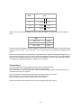
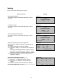
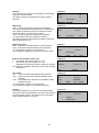
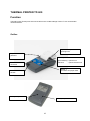
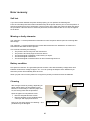
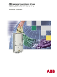
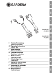
lindab | simplified construction Lindab Leakage Tester and Thermal Printer User Manual FUNCTION .......................................................................................................................... 3 Outline ......................................................................................................................... 3 TECHNICAL DATA ............................................................................................................. 4 Pressure measurement............................................................................................... 4 Flow measurement ..................................................................................................... 4 Adapter type flow range .............................................................................................. 4 General data ............................................................................................................... 4 OPERATION AND MAINTENANCE ................................................................................... 5 SERVICE ............................................................................................................................. 6 Lubrication .................................................................................................................. 6 Fuse ............................................................................................................................ 6 Accuracy and function check ...................................................................................... 6 Guarantee ................................................................................................................... 6 DECLARATION OF CONFORMITY ................................................................................... 7 COMPONENTS ................................................................................................................... 8 Storage and transportation ......................................................................................... 8 Device ......................................................................................................................... 8 Connection for leakage air .......................................................................................... 8 Connection for system pressure ................................................................................. 8 Sealing-off equipment ................................................................................................. 8 Documentation ............................................................................................................ 8 Other things – useful at leakage measurements ........................................................ 8 BACKGROUND TO LEAKAGE TESTING ......................................................................... 9 DEFINITIONS OF USED TERMS ..................................................................................... 10 TESTING PRINCIPLE AND SET-UP ................................................................................ 11 LEAKAGE TESTING ........................................................................................................ 12 Preparation of ductwork system ............................................................................... 12 Sealing-off of ductwork system ................................................................................. 12 Selection of tightness class....................................................................................... 12 Choice of wanted pressure ....................................................................................... 12 Selection of adapter .................................................................................................. 12 Connections .............................................................................................................. 13 TESTING ........................................................................................................................... 14 THERMAL PRINTER TD 600 ........................................................................................... 16 FUNCTION ........................................................................................................................ 16 Outline ....................................................................................................................... 16 TECHNICAL DATA ........................................................................................................... 17 PREPARATIONS FOR USE ............................................................................................. 18 OPERATION ..................................................................................................................... 19 ERROR RECOVERY ........................................................................................................ 20 Self test ..................................................................................................................... 20 Missing or faulty character ........................................................................................ 20 Battery condition ....................................................................................................... 20 Cleaning .................................................................................................................... 20 SERVICE ........................................................................................................................... 21 Guarantee ................................................................................................................. 21 DECLARATION OF CONFORMITY ................................................................................. 22 LINDAB CONTACT........................................................................................................... 23 2 Function The Lindab Leakage Tester measures the leakage of duct work installations by measuring the air flow required to maintain a wanted pressure level. The Leakage Tester is operated via a user guidance system by means of a tactile keypad together with a 4-line, backlit liquid crystal display. The display shows measured data and operating instructions. It is possible to print the results of the test on a wireless pocket printer using the built-in infrared interface. The Leakage Tester can be used for tests with positive and negative pressure. Outline Leakage air connection (for negative system pressure) System pressure connection Leakage air connection (for positive system pressure) Power switch Power connection Display Voltage selector Fuses Keypad Adjustable handle/support Adapters (Type 1 and 2) Infrared interface (for printer) 3 Technical data Pressure measurement Principle Measuring range Resolution Accuracy piezo-resistive semi-conductor sensor -750 to +2000 Pa 1 Pa ±3 Pa or ±2,5 % of reading, whichever is highest Flow measurement Referred to 1 atm = 101 325 Pa and 20 °C Principle mass flow hot film anemometer Measuring range 0,00 to 55,00 l/s Resolution 0,01 l/s Accuracy ±0,03 l/s or ±5 % of reading, whichever is highest Adapter type flow range No adapter Adapter type 1 Adapter type 2 8,00 to 55 l/s 3,00 to 7,99 l/s 0,00 to 2,99 l/s General data Power supply Power consumption Fuse Working temperature range Storage temperature range Main device weight Total weight 230 V, 50 Hz max. 9 A 2 pcs fine wire T10/250D 5x20 mm or 5x30 mm +5 °C to +40 °C -20 °C to +50 °C approx. 9,5 kg approx. 22 kg 4 Operation and Maintenance Inside, the Lindab Leakage Tester are no user-serviceable parts. Therefore, the device should never be opened by the user. The device may be opened by qualified personnel! CAUTION: RISK OF LIFE! 230V 50Hz Except for a light occasional grease on all O-rings at the pressure and air openings and on the adapters the device does not need any maintenance work. To change the fuse first unplug the power cord and then pull out the fuse holder at its top edge. The fuse must only be exchanged to another of the same type. An accuracy and performance test is to be performed regularly (it is suggested 1 x annually) by the factory or by a correspondingly equipped test facility. Figure 5: Name plate and device number. The inlet and outlet openings must be protected from incoming dirt and moisture! The inlet of dust and liquids must be avoided! The strainer in the suction opening at the top of the unit has to be vacuum cleaned from time to time if necessary. For applications in particularly dusty environments, an additional intake filter is available as an optional accessory. Reduced air flow rate may indicate a clogging of the suction opening. (Tested in manual mode, without any connected hoses, the maximum air flow should not be below 40 l/s.) The device should only be operated in a stable electric net and not driven by generators or other power supplies below 230 V or without adequate electric continuous power. The Lindab Leakage Tester is intended as a measuring device. It is not recommended to use it during hours to search for leaks in air distribution systems. If however a lengthy pressurizing with the device, is necessary, no adapter should be used to minimize the power input to the fan. The device may not be operated with any kind of fog or smoke cartridges for leak detection! Risk of breakdown! 5 Service We see service as a very important element in our business. That is why we are still available to you even after the guarantee period has expired. If you send us the device, it will be returned to you by our delivery service after repair in shortest time. The main device has no internal parts that can be serviced by the user. Hence the device shall only be opened by a specialist. CAUTION: RISK OF LIFE 230 V 50 Hz Lubrication An occasional light lubrication with a suitable lubricant of all round sealing rings at the connections for leakage air and system pressure and at the adapters is the only service to be performed by the user. Fuse To change the fuses, first disconnect the electric wire from the main device and then pull the fuse holder out by the upper notch. The fuses may only be replaced with fuses of the same type. Be observant to put the fuse holder back with the correct side down so that the correct voltage arrow points at the white rectangular mark. Accuracy and function check The accuracy and correct functioning of the system should be checked regularly (recommended interval: once per year) by the factory or an appropriately equipped test centre. Guarantee The guarantee period for the Lindab Leakage Tester LT 510 is 12 months from the sales date, provided that it is used correctly. This warranty does not include the costs for transport and packing material in case of repair. The guarantee will be invalid if a not authorized third person repair or change the device. 6 Declaration of Conformity A copy of the Declaration of Conformity issued by the manufacturer is available on our home page www.lindabventilation.com. 7 Components Storage and transportation Aluminium trunks, 2 pcs Device Main device Lindab Leakage Tester LT 510 Adapter Type 1 (in minitrunk) Adapter Type 2 (in minitrunk) Electric wire (length 2,4 m) Fuses (fine-wire T10, 250 V) Printer TD 600 Thermal paper (roll) Batteries (type AA or LR6), 4 pcs Connection for leakage air Plastic hose (Ø 50 mm, length 4 m) Connector (Special female end cap EPF Ø 100) Connection for system pressure Rubber hose (Ø 10 mm, length 10 m) Connector (Special female end cap EPF Ø 100) Sealing-off equipment Seal-off bladder (size 3), 5 pcs Seal-off bladder (size 5), 5 pcs Seal-off bladder (size 10), 5 pcs Air hand pump (For bladder) Documentation Instruction manual (For the main device and leakage test.) Instruction manual (For the printer.) Other things – useful at leakage measurements Plastic sheet Tape Tape measure Stepladder Electric torch Extension lead Additional equipment (note material, camera, knife, sheet metal screws, universal pliers, smoke bottle, scale rule, screw bits and suchlike things) 8 Background to leakage testing The EPBD (Energy Performance of Buildings Directive) standard EN 13779 deals with the general necessity for leakage testing in the interest to save energy and to achieve a well performing airconditioning system. EN 12237 describes the test and requirements for circular ductwork. EN 1507 describes the test and requirements for rectangular ductwork. EN 12599 deals with the handing-over. Leakage of a ductwork system is categorized in ‘tightness classes’. These tightness classes use the concept of ‘leakage factor’ to compare ductwork systems of different sizes and subjected to different pressures. Leakage factor is leakage per ductwork surface area unit and is expressed in (l/s)/m². A is the easiest class to achieve. It permits the highest leakage. B is the second easiest class to achieve. C is the second toughest class to achieve. D is the toughest class to achieve. It permits the smallest leakage. The tightness classes according to EN 12237 and 1507, and analogy to older standards. Contemporary tightness class according to EN 12237 and 1507 A Leakage factor – maximum allowed at class upper limit (l/s)/m² Old tightness class according to EUROVENT 2/2 Old tightness class according to DIN 24194 part 2 0.65 A II 0.65 pt 0.65 pt 0.65 pt B III C IV 0,027 × pt B 0,009 × C 0,003 × D 0,001 × 9 Definitions of used terms Variable Denomination None Explanation Without any adapter. Use At leakage of 8–55 l/s. Adapter Type 1 The biggest adapter. At leakage of 3–7,99 l/s. Type 2 The smallest adapter. At leakage of 0–2,99 l/s. The easiest class to achieve. Permits the biggest leakage. The second easiest class to B achieve. The second toughest class to Tightness C achieve. class The toughest class to achieve. D Permits the smallest leakage. Not a tightness class but a var. mode switch to variable mode. (Not used.) The area of the surface of the Area surface duct system, or part of system, under test. The pressure you input and wanted want the unit to achieve for the test. Pressure The present running pressure present during the test. The finally achieved pressure achieved after the test. The permitted maximum leakage. Calculated from tighpermitted calculated tness class, surface area and achieved pressure. Leakage The present running leakage present during the test. The finally achieved leakage achieved after the test. A 10 Unit To calculate the permitted leakage. To calculate the permitted leakage. To calculate the permitted leakage. To calculate the permitted leakage. To direct input of the wanted leakage. (Not used.) To calculate the permitted leakage. m² As target for the present pressure. Pa To monitor the present pressure. To calculate the permitted leakage. To compare with the achieved leakage. To monitor the present leakage. To compare with the permitted leakage. Pa Pa l/s l/s l/s Testing principle and set-up The following diagram shows the principle of the measurement set-up. Two turbine blowers generates a flow. Which, via the thick leakage air hose, is fed into the sealed-off ductwork. As a result of this incoming air, the present pressure in the ductwork rises. This pressure is, via the thin system pressure hose, fed back to the measuring device. The turbine blowers are regulated by comparing the wanted pressure with the present pressure. Sealing-off bladder Leakage Tester LT 510 Leakage air hose Connector Minimum distance 2m Adapter Duct system under test System pressure hose Connector Sealing-off bladder 11 Leakage testing Preparation of ductwork system Large and complex ductworks, may have to be tested in parts. In order to be able to examine and cure a leaky ductwork a test shall be performed while the ductwork is still accessible, i.e. before it is built in and any insulation is put on. The duct surface area to be tested shall be measured and calculated according to EN 14239. The area shall be at least 10 m² according to EN 12237 and 1507. Sealing-off of ductwork system The ductwork to be tested shall be very well sealed off. From the rest of the system and from the surrounding at all openings, grills etc. This sealing-off is very important and must be done very carefully since failure here will wrongly disadvantage the resulting leakage of the ductwork! Selection of tightness class The wanted tightness class is often decided during the design phase. Choice of wanted pressure The ductwork to be tested shall be subjected to a pressure, positive or negative, preferably its design operating pressure. The pressure shall, according to EN 12237 and 1507, be maintained within ±5 % of the specified value for 5 minutes (= 300 seconds). This will be done automatically by the Leakage Tester. Selection of adapter The main device handles leakage air flows above 8 l/s as it is. If the leakage air flow is below 8 l/s the main device has to be adapted. This is done by inserting one of the two adapters (Type 1 or Type 2) in the leakage air connection on the front side – the connection for positive system pressure. Also at negative system pressure an adapter, if any, is placed in this connection. The magnitude of the leakage air flow depends on the system size and the system pressure. The maximum permitted leakage air additionally depends on the tightness class. Calculate the maximum permitted leakage for any tightness class using the formulas in the following table with the system pressure, p, [Pa] and duct surface area, A, [m²] as input. (The ‘|p|’ in the formulas reads ‘absolute value of p’ and means that if the pressure is positive – just put in, and if the pressure is negative – remove the minus sign and put it in.) 12 Tightness class Permitted leakage [l/s] A 0,027 ⋅ p 0 , 65 ⋅A B 0,009 ⋅ p 0 , 65 ⋅A C 0,003 ⋅ p 0 , 65 ⋅A D 0,001 ⋅ p 0 , 65 ⋅A Then use the so calculated leakage air to pick a suitable adapter using the ranges in the following table. Leakage air range [l/s] Adapter 8,00 – 55 None 3,00 – 7,99 Type 1 0,00 – 2,99 Type 2 Example: System pressure of -400 Pa and duct surface area of 50 m² and tightness class D gives the 0,65 0,65 expression 0,001·|-400| ·50 = 0,001·400 ·50 = 2,46 l/s, which in turn leads to the adapter named Type 2. Note. Since the procedure described above only deals with the maximum permitted leakage for a certain tightness class there may occur cases where the leakage is too small for the so selected adapter. In such a case a smaller adapter has to be chosen. If the leakage cannot be estimated, start without any adapter and gradually change to a smaller one if necessary. Connections Connect the leakage air hose between the main device and the ductwork. At the ductwork – use a male end Ø 100. Seal it off well with tape. At the main device – use the connection on the front side for positive system pressure and use the connection on the top for negative. Connect the system pressure hose between the ductwork and the main device. At the ductwork – use a male end Ø 100. Seal it off well with tape. Keep a minimum distance of 2 m between these connections. Connect the electric wire between the main power supply and the main device. 13 Testing Switch on the device with the power switch. Action/comment Display The program version The display changes automatically to display 2 after 2 seconds. Display 1 Lindab LEAKAGE–TESTER Version T-Check is active The display changes automatically to display 3 after 2 seconds. 1.2 Display 2 Lindab LEAKAGE–TESTER Version 1.2 T–Check active The accumulated test number The display changes automatically to display 4 after 2 seconds. Display 3 Lindab LEAKAGE–TESTER Version 1.2 Test number : Start of test and input of chosen pressure The start screen allows the operator to change the test parameters. <C> switches between the different adapters. <O> changes to display 4.1 for selection of the tightness class. ↑ increments the wanted pressure in steps of 10 Pa. ↓ decrements the wanted pressure in steps of -10 Pa. Holding any arrow key pressed in rushes the change. <N> starts the test with the selected parameters and changes to display 5. Display 4 Input of selected tightness class The class to be chosen is marked with an → . ↑ / ↓ moves the → between the various classes. <C> escapes back to display 4 without making any change. <N> selects the marked class and returns to display 4. Don’t mark and select the “var xx” choice! This is reserved for ‘Variable mode’ and is not used. Display 4.1 14 0 Adapter: TYP1 <C> Class: A <O> P-Test: 400 ↑/↓ <N> →A C TO START TEST 27 l B 9l 3l D 1l ESC <N> SELECT var xx <C> Self test The progress of the self test is indicated by the shrinking of the line of squared dots. The display changes automatically to display 6 after 7 seconds. Display 5 Pres.: Pa Flow: l/s SELFTEST Measuring ‘Pres.:’ means the present pressure in the ductwork. The present pressure works itself up to the wanted pressure. When the wanted pressure is reached, the time countdown starts – from 300 to 0 seconds. ‘Flow:’ means the present leakage at the ductwork. <C> interrupts the test and changes to display 7. The display changes automatically to display 7 when the 300 seconds has run out. Display 6 Measuring result ‘Pres.:’ means the achieved pressure in the ductwork. ‘Flow:’ means the achieved leakage at the ductwork. <C> jumps back to display 4 for a new test. <N> changes to display 8 for input of duct surface area. Display 7 Pres.: 395 Pa Flow: 4.34 l/s <C> 300* Pres.: 395 Pa Flow: 4.34 l/s Test result <C> Input of duct system surface area ↑ increments the area in steps of 0,1 m². ↓ decrements the area in steps of -0,1 m². Holding any arrow key pressed in rushes the change. <N> starts the calculation with the input area and changes to display 9. TO STOP NEW <N> Display 8 Please enter surface: 10.00 m² <N> Test result ‘act.:’ means the achieved leakage at the ductwork. ‘max.:’ means the maximum permitted leakage at the ductwork. ‘Test’ says whether the ductwork has PASSED or NOT PASSED the test. <C> jumps back to display 4 for a new test. <N> changes to display 10 and starts the printing. Display 9 Printing The infrared window of the printer must be held steady and close to the infrared window of the main device during the hole printing process. The display returns automatically to display 9 after 15 seconds. Display 10 act.: max : Test <C> ENTER NEW act.: 4.35 l/s 17.29 l/s PASSED <N> PRINT 4.35 l/s max : 17.29 l/s printing Please wait 15 CALC THERMAL PRINTER TD 600 Function Thermal Printer TD 600 prints out test result from the Lindab Leakage Tester LT 510 via the built-in infrared interface. Outline Paper roll compartment opening lever Paper roll compartment LED – operation indication green blinking = printer is on red blink = printer switches off Button ”O” Off switch Button ”I” On switch and paper feed Infrared interface window Battery compartment Battery compartment lock 16 Technical data Working temperature range Storage temperature range Relative air humidity Power supply Paper 0 °C to +50 °C -10 °C to +60 °C with special paper -40 °C to +60 °C 10 % to 80 %, no condensation 4 × type LR06 (AA) thermal paper, width 57 mm 17 Preparations for use Batteries input and exchange Open the battery compartment cover on the back side of the printer. Press the lock and lift the cover. Be observant of the polarity when putting in the batteries. In order to get optimal performance from your printer use only high efficient alkali batteries. Paper roll input Open the paper roll compartment by pulling the opening lever. The paper roll compartment cover can now be opened. Put in the paper roll. Put the paper roll in the storing grove so that its outer side/end faces the printhead. The paper roll compartment cover must audible snap at the closure. The printer is now ready for use. 18 Operation Switch on the printer by pushing the button ”I”. A green blinking from the LED shows that the printer is ready for use. You can now start to transfer the test result from the main device. Please note, that information transfer only work at ‘free sight’. The distance between the main device and the printer shall be shorter than 1 m and an radiation angle of ±15° shall not be exceeded. Feed the paper at wish by pressing the button ”I”. Switch off the printer by pushing the button ”O” for 3 seconds. A red blink from the LED shows when the printer goes off. In order to prolong the lifetime of the batteries, the printer will automatically be switched off after more than 10 minutes of inactivity. Simply press the button ”I” in order to restart the printer. 19 Error recovery Self test If you are uncertain whether the printer works properly you can perform the following test: From the off mode press both buttons simultaneously till the printer starts to print. It will now perform a self test and print its full set of characters. If this is not the case, switch the printer off again and repeat the procedure. If also this time no self test is performed, and the batteries are not run out, the apparatus is defect. Missing or faulty character The character “?” will be printed when information is lost if the printer doesn’t print the incoming data fast enough. The character “?” will be printed when the printer detects that due to a disturbance or break in the transmission false data would be printed. This could be caused by the following: • The printer is too far away from the main device. • The printer is at a faulty angle to the main device. • The infrared signal is hindered or obscured by an object. • The infrared signal is disturbed. • The infrared signal is interfered from an other infrared signal source. Battery condition First perform a self test. The generated printout contains a line with the battery voltage Ubat. New batteries shall show a voltage of approx. 6 V. You can prolong the lifespan of the batteries if you switch the printer off immediately after each use. When you plan not to use the printer for a longer time period you should remove the batteries. Cleaning Driving roller After a larger amount of printing, depending on paper quality and the environmental circumstances, it is necessary to clean the paper sensor, the driving roller and the printhead. Printhead Open the paper roll compartment cover. • Remove dirt particles with a brush. • Remove deposits on the printhead with a cotton pin and isopropanol alcohol. Paper sensor Don’t ever use sharp objects for cleaning! – The printhead may be damaged. 20 Service The service is in major parts described by us. Because of that we are of course at your service after the guarantee period. • • Send us the device, we repair it and return it via our delivery service. Immediate help is available via our technicians over telephone. Guarantee At correct use the guarantee period for the Thermal Printer is 12 months from the sales date. Excluded are articles of consumption (e.g. batteries). Costs for transport and packing of the device in case of repair is not included the guarantee. 21 Declaration of Conformity A copy of the Declaration of Conformity issued by the manufacturer is available on our home page www.lindabventilation.com. 22 Contact Lindab Belgium LINDAB NV Zeeschipstraat 149 BE-9000 GENT Phone +32 9 385 5011 Fax +32 9 385 6062 www.lindab.be e-mail [email protected] Germany LINDAB GmbH Postfach 1355 DE-22935 BARGTEHEIDE Phone +49 4532 28590 Fax +49 4532 5666 www.lindab.de e-mail [email protected] Poland LINDAB Sp. z o.o. Sadowa, ul. Kolejowa 311 PL-05-092 LOMIANKI Phone +48 22 4898800 Fax +48 22 7519667 www.lindab.pl e-mail [email protected] Czech Republic LINDAB s.r.o. Karlovarská Business Park Na hürce 2 CZ-160 00 Praha 6 - Ruzynê Phone +420 233 107 100 Fax +420 233 107 163 www.lindab.cz e-mail [email protected] Hungary LINDAB Kft. Állomás. ut. 1/A HU-2051 BIATORBÁGY Phone +36 23 531100 Fax +36 23 312011 www.lindab.hu e-mail [email protected] Romania LINDAB SRL Soseaua de Centura, nr. 8 Stefanestii de Jos RO-077175 - ILFOV Phone +40 21209 4100 Fax +40 21209 4124 www.lindab.ro e-mail [email protected] Denmark LINDAB A/S Postbox 1071 Langkaer 20 DK-6100 HADERSLEV Phone +45 73 232323 Fax +45 73 232333 www.lindab.dk e-mail [email protected] Estonia LINDAB AS Saha-Loo tee 4 EE-74114 JOELÄHTME VALD, HARJU MK. Phone +372 6348200 Fax +372 6348210 e-mail [email protected] Finland Oy LINDAB Ab Juvan Teollisuuskatu 3 FI-02920 ESPOO Phone +358 20 785 10 10 Fax +358 20 785 10 73 www.lindab.fi e-mail [email protected] France LINDAB S.A. Parc d’Activités FR-01 120 MONTLUEL Phone +33 47806 3641 Fax +33 47806 3616 www.lindab.fr e-mail [email protected] Italy LINDAB S.R.L Via Pisa 5-7 IT-10088 VOLPIANO (TO) Phone +39 011 9952099 Fax +39 011 9952499 www.lindab.it e-mail [email protected] Latvia LINDAB SIA Kurzemes Pr. 23 LV-1067 Riga LATVIA Phone +371 780 43 71 FAx +371 780 43 80 GSM: +371 9136530 e-mail [email protected] Russia Lindab Co. Ltd 197701, Russia Saint-Petersburg, Sestroretsk st. Voskova, h.2., Litera V. Phone +7 (812) 380 53 60 Fax +7 (812) 380 53 59 www.lindab.ru e-mail [email protected] Sweden LINDAB SVERIGE AB SE-269 82 BÅSTAD Phone +46 (0)431 850 00 Fax +46 (0)431 850 65 www.lindab.se e-mail [email protected] Lithuania LINDAB UAB Mokslininku g. 20 LT-08410 VILNIUS Phone +370 52 729 729 Fax +370 52 729 730 GSM: +370 68 68 48 06 e-mail [email protected] Switzerland LINDAB AG Hofstrasse 94 CH-8620 WETZIKON Phone +41 58 800 3100 Fax +41 44 58 800 3131 www.lindab.ch e-mail [email protected] Norway LINDAB A/S Postboks 171 Kalbakken NO-0903 OSLO Phone +47 22 80 39 00 Fax +47 22 80 39 03 www.lindab.no e-mail [email protected] UK LINDAB Ltd 10 Woodall Road Redburn Industrial Estate Enfield GB-Middlesex EN3 4LE Phone +44 (0)20 8805 3656 Fax +44 (0)20 8805 0558 www.lindab.co.uk e-mail [email protected] 22 EN 2010-04-19, rev 3