Transcript
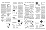
CP7827 – INSTRUCTIONS FOR
COMPRESSION TESTER
Test Procedure
1. Run the engine for about ten minutes or until it reaches normal
operating temperature before performing the compression test.
Fig. 2
Grounded
High Tension Lead
HIGH
TENSION
LEAD
JUMPER
WIRE
2. Stop the engine. Disconnect all
the spark plug wires and number
them in the order in which they
were removed; this makes them
easy to identify for reconnection.
3. Loosen all spark plugs about one
turn, but do not remove them.
Use an air hose or stiff brush to
remove all the dirt from the spark
plug wells. Remove the spark
plugs and place them on a clean,
flat surface in the order in which
they were removed. This procedure will help to correlate any
compression or cylinder problems
with the condition of the plug from
the particular cylinder involved.
4. Remove the air filter and set the
carburetor throttle plates to the
wide open throttle position using
a string or wire. See Figure 1.
5. Remove the high tension lead
from the center of the distributor
and connect to ground as shown
in Figure 2. To disable electronic
ignition systems, disconnect the
electronic ignition module or remove the primary battery terminal from the ignition coil. On GM
HEI V-8 and V-6, disconnect the
primary lead from the distributor
cap. (Figure 3.)
STRING OR WIRE
8. Crank the engine for at least four
compression strokes or until the
pressure reading stops rising on
the gauge.
2. If the needle fails to travel up-scale
as described in Step 1, or if it remains at the same value for several strokes and then starts to climb,
the cylinder has a sticking valve.
9. Record the compression reading, then push the side release
valve to relieve the pressure as
shown in Figure 5. Repeat the
test. Record the reading, relieve
the pressure, remove the gauge
from the hose, and remove the
hose from the spark plug well.
Fig. 5
RELEASE
VALVE
Push
Release
Valve to
Relieve
Pressure
System
PRIMARY
WIRE
10.Reconnect the hose to the next
spark plug well to be tested and
repeat steps 6 through 10 for the
remainder of the cylinders to be
tested.
Test Results
Hold Open
Throttle Plates
CARBURETOR
reaches a peak value. All cylinders
should indicate a pressure that is
within the vehicle manufacturer's
specifications, and the reading
should not vary more than 10%
from cylinder to cylinder.
Fig. 3 Disabled GM HEI Ignition
CAUTION!
Failure to return the carburetor throttle plates to the closed
throttle position before starting the engine can cause serious engine damage.
Fig. 1
7. Insert the spark plug hose into
the gauge by pulling up on the
outer sleeve of the gauge's quick
disconnect coupling and allow it
to snap back as the fitting engages the adapter.
6. Disconnect the hose from the
gauge. Screw the spark plug
adapter hose (Item 3, Figure 6)
into a spark plug well. Hand tighten
only – DO NOT USE A WRENCH.
See Figure 4.
NOTE: On engines with 14mm long
reach plugs, use the long reach
adapter (Item 7, Figure 6). Do not
use the adapter in short reach
holes – it may hit the top of the
piston and damage the engine.
Fig. 4
1. On a normal cylinder, the gauge
needle should travel up-scale on
each compression stroke until it
Fig. 6
3. If the compression reading is considerably higher than the vehicle
manufacturer's specification, it indicates carbon buildup in the cylinder.
4. If a reading on two adjacent cylinders is 20 pounds (or more) lower
than the other cylinders, a defective head gasket is indicated.
Water (coolant) and/or oil may be
found in the two cylinders under
these conditions.
5. If the readings are low or vary
widely between cylinders, pour a
teaspoon of clear S.A.E. grade 30
oil into each cylinder and retest. If
the readings increase considerably, the fault may be due to poorly
seated or worn piston rings. If the
readings remain about the same,
the valves and/or associated components are likely the cause.
6. Clean, regap and reinstall the spark
plugs in the same order in which
they were removed, or install new
spark plugs. Reconnect all spark
plug wires in the proper order.
Remove the string or wire from
the carburetor throttle plates and
make certain it returns to closed
throttle position. Reconnect the
ignition system.
120 150 180
90
8 10 12
14
16
18
2
20
0 kPa x 100
210
6
60
30
4
0LBS.
Compression
Tester
7
240
270
300
per sq. in.
4
6
1
Compression Gauge
Repair Parts
Installation of
Compression Gauge
5
2
Key
No.
1
2
3
4
5
6
7
3
Part No.
Description
0031-000-0246
0180-000-0772
0032-000-0109
0180-000-0775
0400-000-1350
0400-000-1349
0180-000-0895
0002-004-2018
Compression Gauge
Quick Disconnect Coupling & Valve Assembly
Spark Plug Hose Assembly
(2 ea) Air Valve (High Pressure)*
O-ring
(2 ea) O-ring
Deep Reach Adapter
Instruction Manual (Not illustrated)
*NOTE: Do not use automotive tire air valve as a replacement part.
ACTRON
HAND TOOLS