Transcript
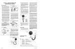
GENERAL MOTORS HIGH ENERGY IGNITION – DISABLING PROCEDURES Instructionsfor RemoteStarter Switch WARNING! Before connecting the Remote Starter Switch, set the transmission gear lever in the “Park” position for automatics or “Neutral” position for manual transmissions and engage the emergency brake. NOTE: It is important to follow the instructions in the order shown below. DISABLING PROCEDURE 1. Disable the ignition system as described under the “Ignition Disabling Procedures” Section as applies to the type of vehicle under test. STARTER RELAY: FORD-AMC FIG. 1 To battery To starter motor This relay may have three or four terminals: two large ones and one or two small ones. Remove the wires connected to the small terminal if only one small terminal is provided. If two small terminals are present, Terminal S remove the wires from the small terminal marked “S”. Connect one lead of the Remote Starter Switch to the bare small terminal (where the wires were just removed) and the other lead of the Remote Starter Switch to the Battery Terminal of the relay. Crank the engine by depressing the Remote Starter Switch. STARTER RELAY: CHRYSLER 2. Connect the Remote Starter Switch as shown in the “Connection Procedure” Section. Exercise care when making this connection because battery voltage is present at the solenoid or starter relay and injury could result by shorting the leads. Remove the “Y” shaped during test connector from the relay as shown in Figure 2. The single terminal connector must remain connected at the lower right hand corner of the relay and the other single terminal Connected during test connector must remain connected to the “SOL” relay terminal as shown. Connect one lead of the Remote Starter Switch to the ‘EGR’ terminal of the relay and the other lead of the Remote Starter Switch to the Positive (+) post of the battery. Crank the engine by depressing the Remote Starter Switch. CAUTION! If the vehicle is equipped with an engine “HOT” indicator, the lamp test circuit which is in the ignition system could be damaged if the remote starter switch is energized with the ignition switch in the “OFF” position. 4. After the Remote Starter Switch has been properly connected, pull the trigger on the Remote Starter Switch. The engine should crank over. 5. After removing the Remote Starter Switch, reconnect the leads that were disconnected during the “Ignition Disabling Procedure” Section. CONNECTION PROCEDURE The following diagrams illustrate five of the most common starter relay and solenoid arrangements and the method of connection to the remote starter switch. Match the system you have to one of the diagrams and follow the individual instructions carefully. CAUTION! Battery voltage is always present at the starter relay or solenoid terminals and could cause personal injury if shorted to ground through tools, wires or wristwatch. Disconnected STARTER RELAY: CHRYSLER K-CARS Remove the “U” shaped 5 terminal connector from the relay as shown in Figure 3. The single terminal connector must remain connected to the top of terminal 3 of the relay, however, connect one lead of the Remote Starter Switch to the bottom of terminal 3 on the relay and the other lead of the Remote Starter Switch to the POSITIVE (+) post of the battery. Crank the engine by pulling the trigger on the Remote Starter Switch. ONE YEAR WARRANTY If within one year from the date of purchase this equipment fails due to defect in materials or workmanship, return it to Actron and Actron will repair it free of charge. This warranty gives you specific legal rights, and you may also have other rights which may vary from state to state. ACTRON Insert spade terminals (not supplied) into cavities 1,6, and 8 of the Diagnostic Connector as shown in Figure 4. Connect a jumper wire from terminal 6 to engine ground. Connect one lead of the Remote Starter Switch to terminal 1 of the Diagnostic Connector and the other lead of the Remote Starter Switch to terminal 8 of the Diagnostic Connector as shown. Crank the engine by pulling the trigger on the Remote Starter Switch. Disconnect primary wire from the BAT terminal on the distributor cap. CAUTION: The tachometer terminal must NEVER be connected to ground at the distributor cap as damage to the distributor module can result. NOTE: This diagnostic connector is usually located on the driver’s side in the engine compartment. Do not confuse it with Air Conditioning diagnostic connector on the passenger side. FIG. 3 FIG. 5 STARTER SOLENOID: GENERAL MOTORS Connect one lead of the Remote Starter Switch to the small terminal of the solenoid marked “S” and the other lead of the Remote Starter Switch to the heavy battery cable as shown. Crank the engine by pulling the trigger on the Remote Starter Switch. Primary wire To battery FIG. 8 SYSTEMS WITH SEPARATE COIL Jumper wire Remove the coil connector (primary) and the high-tension wire from coil secondary terminal. Connect jumper wire between coil secondary terminal and ground on engine. "S" Terminal Engine ground CONVENTIONALIGNITION SYSTEM OR ELECTRONIC SYSTEM WITH SEPARATE COIL Connected during test HEI WITH ELECTRICAL DIAGNOSTIC CONNECTOR AMC-FORD-CHRYSLER Disconnected during test FIG. 7 SYSTEM WITH COIL IN DISTRIBUTOR CAP Located under hood FIG. 2 CONNECTION PROCEDURE 3. Turn the ignition switch to the “ON” position before using the Remote Starter Switch. GENERAL MOTORS: DIAGNOSTIC CONNECTOR When performing Diagnostic System tests on General Motors vehicles equipped with High Energy Ignition (HEI), the engine can be prevented from starting as follows: FIG. 4 Disconnect the primary wire from the BAT (battery) terminal of the ignition coil. Remove the high tension lead from the center of the Battery distributor and ground it as shown in Figure 6. FIG. 6 Insert the GM Diagnostic Jumper Connector Terminal wire in terminal No. 6 of Electrical Diagnostic Connector. Connect jumper wire between this terminal and a good ground Remove Distributor Jumper Engine ground Coil Primary lead to distributor or electronic ignition module Module Electronic ignition FIG. 9 CAUTION: The tachometer terminal must NEVER be connected to ground at the distributor cap, as damage to the distributor module can result. Electrical diagnostic connector terminal Electrical diagnostic connector Engine ground HAND TOOLS