1
®
ure 2) and plug the valve on the bottom with
tape or other suitable means.
CP7803
VACUUM GAUGE/
PRESSURE TESTER KIT
INSTRUCTIONS
5. Using the hose supplied, connect the Vacuum
Gauge to a source of manifold vacuum. This
may be a fitting on the carburetor below the
throttle plate, or a fitting in the intake manifold.
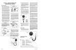
See Figures 2 and 9.
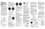
CRANKING VACUUM TESTS
(After testing, return adjustment screws to their
original positions.)
Engine Condition Test
Test Results
1. Start engine and allow it to warm to normal
operating temperature. Stop engine. To prevent the engine from starting, disable the ignition system.
The general condition of an engine is indicated by
one of three possible gauge readings:
2. Remove the air filter. Back out the idle speed
screw (see Figure 1) until the throttle valve is
tighly closed. If the carburetor is also equipped
with an idle air bleed screw, turn the screw
clockwise until it bottoms lightly. In both cases,
count the number of turns so the screws can be
returned to their original positions after the tests.
3. If the vehicle is equipped with an idle stop
solenoid (See Figure 1), disconnect the electrical wire at the base of the solenoid under the
rubber boot or at the connector as shown.
4. If the engine is equipped with a PCV (Positive
Crankcase Ventilation) system, remove the PCV
valve at the engine rocker arm cover (see Fig-
6. Crank the engine and note Vacuum Gauge
reading.
A. (Figure 3) A reasonably steady vacuum reading of 4 inches or more on emission controlled
engines, and 10 inches or more on non-emission controlled engines (pre-1968) indicates
correct engine vacuum. Readings may vary
considerably on different engines, but should
not fall below these minimums. (See
manufacturer’s specifications).
5
0
15
Engine
Vacuum
Fuel 3
Pump 4
7
10
DISCONNECT
ELECTRICAL
CONNECTOR OR
TERMINAL UNDER
RUBBER COVER
2
Fuel 3
Pump 4
Fig. 2
SOURCE OF
MANIFOLD
VACUUM
CLOSED
BREATHER
CAP
AIR CLEANER
PCV
VALVE
ROCKER ARM
VALVE COVER
Fuel 3
Pump 4
psi
6
7
8
5
6
7
9
10
20
7
9
25
10
10
1. Unplug the PCV valve, plugged previously with
a piece of tape (Step 4, Cranking Vacuum
Tests) and crank engine.
A. If the PCV valve is operating properly, the
vacuum will drop to about one-half the value
noted in Step 6, Cranking Vacuum Tests.
9
15
Fuel 3
Pump 4
30
6
7
2. Worn carburetor throttle shaft.
3. Leaking vacuum lines.
4. Improper valve timing.
5. Slow engine cranking due to:
A. Battery
B. Battery cable connections
C. Defective starter motor
D. Excessive mechanical drag in engine caused by:
1. Tight fitting pistons in rebuilt engine.
2. Thickened oil due to excessive oxidation.
C. (Figure 5) A reading which pulses unevenly
indicates a leaky condition which affects one or
more, but not all cylinders.
10
30
15
3
4
5
1
Engine
Vacuum
2
Fuel 3
Pump 4
psi
6
7
8
5
2
0
3
4
5
2
2. Return the idle screw (and idle air bleed screw)
to its original position. (See Step 2, Cranking
Vacuum Tests).
7
10
6. Re-install the PCV valve in its proper location.
psi
6
20
9
5. Re-connect all hoses and vacuum lines.
6
7
8
5
25
C. No change in the vacuum indicates a clogged
PCV valve.
4. Re-connect the wire to the idle stop solenoid.
1
2
1
Engine
Vacuum
B. A reading much lower than one-halfindicates
excessive flow which could upset the proper
carburetor air/fuel ratio causing rough idling
and burned valves.
3. Re-enable the ignition system.
0
10
1
0
(Partially blocked muffler or tailpipe.)
POSITIVE CRANKCASE
VENTILATION (PCV) VALVE TEST
5
0
With vacuum gauge connected to a source of
manifold vacuum, increase engine speed to 2000
RPM, maintain this speed, and note the vacuum
gauge reading. A gradually decreasing vacuum
reading may indicate a restricted exhaust system.
30
Fig. 7
5
psi
Check for:
1. Leaking carburetor flange gasket.
IDLE STOP
SOLENOID
2
1. Connect the vacuum gauge to a source of
manifold vacuum. See Figures 2 and 9.
6
7
8
5
6
B. (Figure 4) An excessively low, steady vacuum
is caused by a condition which affects all cylinders equally.
RUBBER
COVER
3
4
5
1
Engine Condition Test
25
IDLE MIXTURE
SCREWS
2
0
Engine
Vacuum
15
While performing a running vacuum test, it is
possible to obtain a different gauge indication than
that obtained under the cranking vacuum test.
20
IDLE
SPEED
SCREW
1
RUNNING VACUUM TEST
3
4
5
1
Engine
Vacuum
psi
6
7
8
5
6
30
15
0
10
Check for:
20
1. Burned or stuck valve.
25
2. Intake manifold leak
at one cylinder.
3. Worn intake valve
guide.
4. Broken piston or piston rings.
Fig. 6
2
0
3
4
5
2
20
1
2
1
5
0
10
1
0
25
Fig. 1
5
10
EXHAUST RESTRICTION TEST
Fig. 5
2. Run the engine at normal operating temperature and idle speed.
Fig. 4
Fig. 3
NOTE: A certain amount
of even pulsing is normal, notably on 6 and 4
cylinder engines, and
does not necessarily indicate a leaky condition.
9
30
Test Results
A. (Figure 6) A steady reading between 15 and 22
inches indicates a mechanically sound engine.
B. (Figure 7) A pointer which sweeps or wanders
erratically through several inches indicates a
malfunction affecting all cylinders unequally
and inconsistently. To help isolate the troubled
area, run the engine at about 2000 RPM. If the
pointer steadies, check for:
1. Ignition and/or timing.
2. Carburetor mixture adjustment at idle.
If the sweep gets larger, check for weak or
broken valve springs. If the sweep becomes
shorter and more rapid, check for:
1. Carburetor or intake manifold leaks.
2. Sticky valves.
PCV SYSTEM TEST
1. Operate the engine at normal temperature and
idle speed.
2. Remove the hose connected between the air
cleaner and valve cover or oil filler/breather cap
as shown in Figure 8. Plug the oil dipstick tube
to prevent an air leak.
Fig. 8
FILLER/BREATHER CAP
5
0
10
1
2
0
15
3
4
5
1
Engine
Vacuum
2
Fuel 3
Pump 4
psi
6
7
8
5
6
20
7
25
10
VENT
HOSE
9
30
UNIVERSAL
RUBBER
ADAPTER
PLUG OIL
DIPSTICK HOLE
AIR
CLEANER
3. Hold the vacuum gauge with rubber universal
adaptor firmly over the valve cover hole or filler/
breather cap opening.
A. A properly working PCV system will draw a
vacuum of about 3 to 5 inches within 10 seconds.
B. If there is very little or no change in the
gauge reading in the first 10 to 15 seconds of
the test the PCV valve is clogged or frozen, or
there is excessive air leakage in the vacuum
hose between the intake manifold and PCV
valve (or other leakage into the crankcase).
NOTE: The vacuum reading can appear to be
normal during the above tests while the advance
mechanism is defective; that is, frozen due to rust,
dirt or corrosion.
CAUTION: Use extreme care in disconnecting
fuel lines. Catch all gasoline in a container and
discard. Leaking gasoline is a serious fire
hazard.
Check the rubber fuel lines at the fuel pump for
deterioration, such as splitting, cracking and
spongyness.
The amount of spark ignition advance needed is
determined by the intake manifold vacuum and
engine speed.
If leaks are evident in lines or fittings, repair or
replace as necessary. If leakage is detected in the
pump at the diaphragm flange, in the sheet metal
cover, or in casting breather holes, replace the
fuel pump. Check fuel level and remove any kinks
in the fuel line. It is not necessary to remove the
fuel pump for any of these inspections.
5
Procedure
1. Disconnect the fuel line between the fuel pump
and the carburetor and attach the vacuum gauge
hose to the fuel line, using adaptors as necessary. (See Figure 10).
0
10
1
2
0
3
4
5
1
Engine
Vacuum
2
Fuel 3
Pump 4
psi
6
7
8
5
6
20
7
25
10
9
30
MANIFOLD VACUUM
CONNECTION
Test Results
On many systems, little or no vacuum is applied to
the distributor at idle; as the throttle is opened wider
(engine RPM increases), the vacuum gradually increases. The manifold vacuum drops when the engine is accelerated in proportion to the amount of
throttle advance. The gauge should read between
18 and 21 for normal engines. Check vehicle manual
for your car for proper value.
If the vacuum gauge does not change or changes very
little with a change in RPM as described above, the
vacuum hose may be open or cracked, or the diaphram
in the advance mechanism may be punctured.
ACTRON
Before testing, check tightness of all fittings and
connections.
NOTE: The fuel in the carburetor fuel bowl will be
sufficient to run the engine for these tests.
15
0
1
0
15
2
5
G
A
S
O
L
IN
1
E
TO
FUEL
TANK
1. Operate engine with fuel line connected to fill
carburetor fuel bowl. Stop Engine.
2. Disconnect the fuel line at the carburetor and
connect a flexible hose to the fuel line using the
adapter as shown in Figure 11. Insert the other
end of the hose in a proper gasoline container.
3. Have an assistant start the engine. While holding the gasoline can, carefully collect the discharge from the fuel pump for exactly 30
seconds. The assistant must count off the time
precisely and turn off the engine after the 30
seconds to get an accurate measurement. Reconnect the fuel line to the carburetor.
4. Remove the gasoline from the engine area.
Pour the contents of the gasoline can into
another container marked off in fluid ounces
such as a kitchen measuring cup. Record the
fuel quantity.
Test Results
Consult the manufacturer’s specifications for required fuel delivery rate. If specifications are not
readily available, use the following table as a guide.
CARBURETOR
CONNECTION
5
4
6
5
Test Results
Engine Displacement
(CID)
Up to 225
225 to 350
Over 350
Ozs. Collected
(30 seconds)
8
11
16
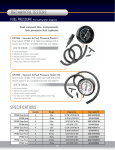
Vacuum & Pressure Tester Kit
Repair Parts
Key
No.
Part No.
1
31-269
Vacuum and Pressure Gauge
2
400-384
Black Rubber Hose for air
and fuel (24")
3
1000-1113 Universal Adapter –
Fuel line, air and PVC
4
400-810
"Tee" Fitting
5
400-819
Tapered Hose Adapter
6
180-784
1/8 NPT X 0.187 Barb
Description
2-202002 Instruction Manual
One Year Warranty
If within one year from the date of purchase this
equipment fails due to defect in materials or workmanship, return it to Actron and Actron will repair it
free of charge.
This warranty gives you specific legal rights, and you
may also have other rights which may vary from state
to state.
If the above conditions are not met, replace or
repair the defective components.
0
10
1
2
0
15
30
VOLUME TEST
5. After taking all measurements, return the fuel to
the vehicle’s gas tank.
Fig. 10
3
2
2. Operate the engine at idle. Hold gauge at
carburetor height and note the reading. Stop
engine and re-connect fuel line.
Compare the observed reading with the
manufacturer’s specifications. If specifications are
not immediately available, fuel pump pressure
can be considered satisfactory if it is between 4
and 6 PSI, with lower readings for smaller displacement engines. If pressure reading falls outside this range, consult the manufacturer’s specifications before replacing the fuel pump.
2
3
4
5 psi
6
7
6
7
8
9
10
1
Engine
Vacuum
Fuel 3
Pump 4
FUEL PUMP TESTING
DISTRIBUTOR VACUUM
ADVANCE MECHANISMS
ALTERNATE VACUUM
CONNECTION ON CARBURETOR
5
10
25
Initial Inspection
Fig. 9
Fig. 12
20
4. Repair or replace the defective parts as needed
and reconnect hoses.
The vacuum advance mechanism in the distributor
is connected to the intake manifold or carburetor by
a rubber hose. To measure the amount of vacuum
at any RPM, disconnect the hose from the distributor and insert a “Tee” connector (Item 4, Figure 12)
in line with this hose and another back to the
distributor as shown in Figure 9. Also, connect the
gauge to the “Tee” as shown.
CARBURETOR
CONNECTION
Fig. 11
3
4
5
1
Engine
Vacuum
2
Fuel 3
Pump 4
7
25
10
®
psi
6
7
8
5
6
20
9
30
TO
FUEL
TANK
Actron Manufacturing Company
HAND TOOLS