1
INSTALLATION INSTRUCTIONS
The primary controller should indicate that the action was successful. If the
controller indicates the action was unsuccessful, please repeat the procedure.
- Brick, tile or concrete walls block more of the RF signal than walls made of wooden
studs and plasterboard (drywall).
Once the switch is part of the network, the same basic procedure is used to add
the switch to groups & scenes or change advanced functions. Refer to the primary
controller’s instructions for details.
- Wall mounted Z-Wave devices installed in metal junction boxes may suffer a
significant loss of range (approximately 20%) since the metal box blocks a
large part of the RF signal.
Please Note: After a power failure, the ZW15S on/off switch returns to OFF state.
ADVANCED OPERATION
The following Advanced Operation parameters require that you have an advanced
controller. However, basic remotes do not have this capability.
Effects of Home Construction on Wireless Range Between
Z-Wave Enabled Devices.
Note: The distances shown in the table below are typical examples. Actual
performance in your home will vary.
All-ON and All-OFF
From the Remote (or repeating Z-Wave module) to
destination device:
Depending upon your primary controller, the ZW15S switch can be set to respond to
ALL-ON and ALL-OFF commands in up to four different ways.Some controllers may
not be able to change the response from its default setting. Please refer to your
controller’s instructions for information on whether or not it supports the configuration
function and if so, how to change this setting.
Type of
Construction
Wood Frame with
Drywall
Brick, Tile or
Concrete
Plastic
J-Boxes*
Metal
J-Boxes
Plastic
Metal
J-Boxes* J-Boxes
0** 100’
80’
100’
80’
1
70’
56’
60’
48’
2
49’
39’
36’
29’
3
34’
27’
21’
17’
The four possible responses are:
Number of
Walls or
Obstacles
- It will respond to ALL-ON and the ALL-OFF command (default).
- It will not respond to ALL-ON or ALL-OFF commands.
- It will respond to the ALL-OFF command but will not respond to the ALL-ON command.
- It will respond to the ALL-ON command but will not respond to the ALL-OFF command.
LED Light and Buttons Configuration
By default setting, once press button "up", the load connected to ZW15S will be
turned on,and LED light will turn off. We use Command_Class_Configuration
to configure LED light state and button reverse.
Restoring Factory Defaults
All Configuration Parameters can all be restored to their factory default settings by
using your primary controller to delete/reset the device.
For instance, after configuring, once press button "up", the load connected to
ZW15S can be turned off and LED light will turn off.
Configuration details
- Parameter 1 (configure LED light state ), default value is 0. Valid values are 0 and
1 with 1 byte.
- Parameter 2 (configure button toggle), default value is 0. Valid values are 0 and
1 with 1 byte.
WIRELESS RANGE
This device complies with the Z-Wave standard of open-air, line of sight transmission
distances of 100 feet. Actual performance in a home depends on the numbers of walls
between the remote controller and the destination device, the type of construction and
the number of Z-Wave enabled devices installed in the control network. Most Z-Wave
enabled devices act as signal repeater and multiple devices result in more possible
transmission
routes which helps eliminate " RF dead-spots."
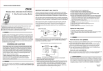
NETWORAV
Z-WAVENTORK
Things to consider regarding RF range:
- Each wall or obstacle (i.e.:refrigerator, big screen TV, etc.)between the remote or
Z-Wave device and the destination device will reduce the maximum range of 100
feet by approximately 25-30%.
-04-
FCC COMPLIANCE STATEMENT
The equipment has been tested and found to comply with the limits for a Class
B Digital Device, pursuant to part 15 of the FCC Rules. These limits are designed
to provide reasonable protection against harmful interference in a residential
installation. This equipment uses,generates and can radiate radio frequency
energy and, if not installed and used in accordance with the instruction, may
cause harmful interference to radio communication. However, there is no
guarantee that interference will not occur in a particular installation. If this
equipment does cause harmful interference to radio or television reception,
which can be determined by turning the equipment off and on,the user is
encouraged to try to correct the interference by one or more of the following
measures:
- Reorient or relocate the receiving antenna
- Increase the separation between the equipment and receiver
- Connect the equipment into an outlet on a circuit different from that to which
the receiver is connected
- Consult the dealer or an experienced radio/TV technician for help.
Operation is subject to the following two conditions:
- This device may not cause interference
- This device must accept any interference, including interference that may
cause undesired operation of the device.
-05-
WARRANTY INFORMATION
Our company warranties its products to be free of defects in materials and workman-ship for a period of two (2) years. There are no obligations or liabilities on the part
of our company for consequential damages arising out of or in connection with the
use or performance of this product or other indirect damages with respect to loss
of property, revenue, or profit, or cost of removal, installation or reinstallation.
Mar, 2014
11002A