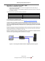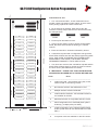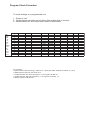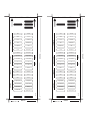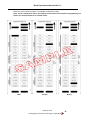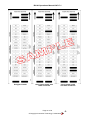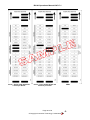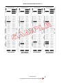
1
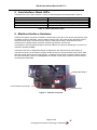
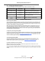
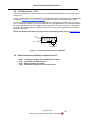
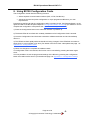
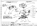
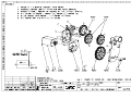
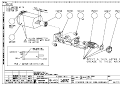
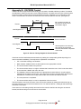
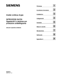
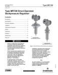
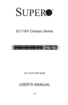
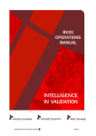
BV100 Operations Manual
BV100-1 Operations Manual
Innovative Technology
Secure Banknote Handling Solutions Of The Future
© Copyright Innovative Technology Limited 2007
®
BV100 Operations Manual GA717-1
Revision History
INNOVATIVE TECHNOLOGY LTD
Title:
Drawing No
BV100 OPERATIONS MANUAL
Author
Date
FORMAT
GA717
RJS
Issue
Issue A
Release Date
10/10/07
Issue 1
04/12/07
10/10/07
Modified By
RJS
First Draft
RJS
MS Word 2000
Comments
First Release
Page 2 of 52
© Copyright Innovative Technology Limited 2007
®
BV100 Operations Manual GA717-1
CONTENTS
1.
INTRODUCTION ......................................................................................................................... 5
2.
SCOPE OF DOCUMENT ............................................................................................................ 6
3.
ENVIRONMENT AND POWER REQUIREMENTS ..................................................................... 7
4.
GENERAL DESCRIPTION .......................................................................................................... 8
5.
USER INTERFACE: BEZEL LED’S ............................................................................................. 9
6.
MACHINE INTERFACE: HARDWARE........................................................................................ 9
6.1
Interface Connector Pin Details ............................................................................................. 10
6.2
Configuration Button Functions .............................................................................................. 11
6.3
Hardware Options .................................................................................................................. 12
7.
MACHINE INTERFACE: PROTOCOLS .................................................................................... 13
7.1
Parallel Input and Output: ...................................................................................................... 13
7.2
Pulse Stream Output .............................................................................................................. 14
7.3
Binary Output – BIN ............................................................................................................... 15
7.4
Low Power Option .................................................................................................................. 16
7.5
Serial Input/Output – SIO ....................................................................................................... 18
7.6
Smiley® Secure Protocol - SSP ............................................................................................. 21
7.7
Multi-Drop Bus / Internal Communications Protocol (MDB/ICP)............................................ 22
7.8
CCTalk Protocol – CCT.......................................................................................................... 24
7.9
Other Interfaces available by request from ITL ...................................................................... 24
8.
USING BV100 CONFIGURATION CARDS............................................................................... 25
9.
MECHANICAL INSTALLATION................................................................................................. 26
10.
ROUTINE MAINTENANCE ....................................................................................................... 28
10.1
11.
Re-Calibration ........................................................................................................................ 28
SUPPORT TOOLS .................................................................................................................... 29
11.1
Configuration Cards. .............................................................................................................. 29
11.2
ITL Bank Note Validator Currency Manager .......................................................................... 29
11.3
Validator Programming System (DA3) ................................................................................... 30
11.4
Internet Website Support ....................................................................................................... 30
Page 3 of 52
© Copyright Innovative Technology Limited 2007
®
BV100 Operations Manual GA717-1
11.5
E-mail Support ....................................................................................................................... 30
Appendix A – Exploded Diagrams ................................................................................................ 31
Appendix B – ESCROW Control ................................................................................................... 39
Appendix C – Interface Tools DA1 – DA2..................................................................................... 40
Appendix D – Configuration Cards................................................................................................ 42
Appendix E – Cash Boxes............................................................................................................. 50
Appendix F – PC System Specification......................................................................................... 52
Page 4 of 52
© Copyright Innovative Technology Limited 2007
®
BV100 Operations Manual GA717-1
1. Introduction
This manual describes the operation of the BV100 Bank note Validator as fitted with Firmware
Version 4.00 or greater.
CAUTIONS:
• THIS PRODUCT MUST BE FITTED WITH A 3 AMP FUSE BEFORE USE.
• THE BV100 VALIDATOR IS PIN FOR PIN COMPATIBLE WITH NV7/8/9/10, BUT NOT
PIN FOR PIN COMPATIBLE WITH THE NV2/3/4/4X OR 5 SERIES PRODUCTS.
• DUE TO DIFFERENT NOTE CYCLE TIMES THERE MAY BE TIMING DIFFERENCES
FROM THE NV PRODUCTS.
We recommend that you study this manual as there are many new features permitting new uses and
more secure applications.
If you do not understand any part of this manual please contact the factory, contact details are below,
for assistance. In this way we may continue to improve our product.
Innovative Technology Ltd.
Derker Street
Oldham
England
OL1 4EQ
Tel:
+44 (0) 161 626 9999
Fax:
+44 (0) 161 620 2090
E-mail:
[email protected]
Web site:
www.innovative-technology.co.uk
WARNING
ONLY SUITABLY TRAINED PERSONNEL SHOULD CARRY OUT ANY WORK ON THIS
EQUIPMENT IN ACCORDANCE WITH ALL CURRENT LOCAL, NATIONAL AND
INTERNATIONAL HEALTH AND SAFETY REGULATIONS.
Smiley® and the ITL Logo are international registered trademarks and they are the property of Innovative
Technology Limited.
Innovative Technology has a number of European and International Patents and Patents Pending protecting
this product. If you require further details please contact the factory.
Innovative Technology is not responsible for any loss, harm, or damage caused by the installation and use of
this product. This does not affect your local statutory rights. If in doubt please contact Innovative Technology for
details of any changes
Page 5 of 52
© Copyright Innovative Technology Limited 2007
®
BV100 Operations Manual GA717-1
2. Scope of Document
This document is intended for those who will:
• Install the BV100 equipment.
• Maintain the BV100 equipment.
Although information is included which will allow a degree of fault diagnosis and repair, it is
recommended that for all but simple mechanical repairs, the unit must be returned to an approved
service centre for repair.
CAUTIONS:
•
NEVER EXCEED THE RECOMMENDED ENVIRONMENTAL AND ELECTRICAL LIMITS.
•
DO NOT ATTEMPT TO LUBRICATE THE MECHANISMS AS THIS MAY AFFECT THE
NOTE TRANSPORT.
•
DO NOT POLISH THE LENS AS THIS MAY ALTER THE OPTICAL CHARACTERISTICS.
•
IF THE BV100 VALIDATOR IS DISASSEMBLED THE UNIT MUST BE RE-CALIBRATED
AND RE INITIALISED, FOLLOWING RE-ASSEMBLY.
Innovative Technology Ltd has a policy of continual product improvement. As a result the products
supplied may vary from the specification described here.
Page 6 of 52
© Copyright Innovative Technology Limited 2007
®
BV100 Operations Manual GA717-1
3. Environment and Power Requirements
This section details the Environmental and Power requirements.
Environment
Temperature
Humidity
Minimum
Maximum
+3oC
+50oC
5%
95% Non condensing
Table 1 - Environmental Requirements
CAUTION:
•
•
IF THE INPUT VOLTAGE FALLS BELOW 11.5V THE BV100 MAY NOT OPERATE
CORRECTLY (WILL REJECT NOTES). THE FRONT BEZEL LIGHTS WILL FLASH TO
INDICATE INCORRECT CONDITIONS
IT IS RECOMMENDED THAT THE POWER SUPPLY USED CAN SUPPLY AT LEAST
2.5 AMPS.
Electrical Supply
Supply Voltage (V DC) Absolute Limits
MDB IF5 Version Supply Voltage
MDB Hardware version
Supply Ripple Voltage
Supply Currents:
Sleep (Low Power Mode)
Standby
Validating
Peak (Motor Stall)
Minimum
+11.5V
+18V
+18V
0
Maximum
+14.2V
+48V DC or 34V AC
+48V DC
0.25V @100 Hz
TBC
230mA
500mA
2000mA
Table 2 - Power Requirements
Interface Logic levels
Inputs
Logic Low
0V To +0.5V
Outputs with 2K2Ω pull up
0.6V
Maximum Current Sink
50mA per output
Logic High
+3.7 V +12V
Pull up voltage of host
interface
Table 3 - Interface Logic Levels
Page 7 of 52
© Copyright Innovative Technology Limited 2007
®
BV100 Operations Manual GA717-1
4. General Description
BV100 Validator - the next generation of ITL Bank Note Validators
The BV100 Bank Note System is a compact note-validating machine (see figure 1), suitable for most
money machines. It will accept up to 16 different denominations of notes in the serial control mode.
Figure 1 – The BV100
The BV100 Validator leaves the factory preset to at least one currency so that it is ready for
immediate installation. If it is required to change the currency data set this may be done using the PC
based Validator Management software.
Various size cash boxes are available for the BV100, ranging from approximately 350 notes to a
maximum of approximately 950 notes (See Appendix E – Cash Boxes for more information).
A lock can be fitted to the BV100 to secure the cash box in place. A lock such as Camlock, prod ref.
2181D can be used.
New currencies and applications are being tested all the time, please refer to our web site or contact
the factory for information concerning specific currencies if they are not already included on our
approved list.
The BV100 is designed for easy installation in most machines.
Interfacing the Validator is very simple, with the choice of the following protocols:
SSP
PULSE
PARALLEL
BINARY
CCTALK
SIO
MDB
NIS
IF30
IF31
IF32
Table 4 – Available Interfaces/Protocols
Page 8 of 52
© Copyright Innovative Technology Limited 2007
®
BV100 Operations Manual GA717-1
5. User Interface: Bezel LED’s
The Bezel LED’s are used to indicate a variety of status signals as described below in table 5.
LED Status
Permanent On
Slow flash on power up (1 second period)
Slow flash (1 second period)
Short flash
Description
Validator enabled ready to accept notes
Power supply is incorrect, check specification
Validator in Configuration card programming mode
Cash box removed
Table 5 – Bezel LED status codes
6. Machine Interface: Hardware
The BV100 interface connector is located on the left side of the unit; it has 16 pins (see figure 2) refer
to Table 6 for the pin allocation. Two are used for the 0V and +12V power supply and there are five
outputs and five inputs, the remaining four pins are reserved for factory use and should not be
connected. An example mating connector is Molex type Part No: 39-51-2160.
It is possible to use the special hardware versions of BV100 in machines operating at 110 Volts or in
machines operating at MDB.
The BV100 also has a Configuration Button located above the USB Connector (See Figure 2).
The USB connector can be used to program the BV100 and for communications when used in SSP
and SIO modes. When used for programming, no external power supply is required. When used for
the communications, power must be applied to the BV100 via the 16 pin interface connector before
connecting the USB cable.
Configuration Button
16 Pin Interface Connector
USB Connector
Figure 2 – Interface Connector
Page 9 of 52
© Copyright Innovative Technology Limited 2007
®
BV100 Operations Manual GA717-1
6.1
Interface Connector Pin Details
The connector pin details are described below (see table 6); they use an IDC 16-pin 0.1" pitch header
with 2 rows of 8 pins.
Pin
1
2
15
1
Name
Description
Open Collector Output. Function changes depending on Machine
Interface Protocol. (See individual interface descriptions for details)
Also the Pulse Stream output
Also the serial Output pin in SSP Serial Mode, and other serial modes
Vend 1
2
Vend 2
3
Vend 3
4
Vend 4
5
16
Open Collector Outputs.
Function changes depending on Machine Interface Protocol.
(See individual interface descriptions for details)
Inhibit channel 1 by holding this pin HIGH. To Enable a channel the
inhibit must be held LOW. Also the serial Input pin in SSP Serial Mode,
and other serial modes
Inhibit 1
6
Inhibit 2
Inhibit channel 2 by holding this pin HIGH
7
Inhibit 3
Inhibit channel 3 by holding this pin HIGH
8
Inhibit 4
Inhibit channel 4 by holding this pin HIGH
9
10
Busy
BV100 is validating and stacking output. Active low while the BV100 is
reading, transporting or stacking a note.
Escrow
Operate Escrow function by holding LOW (see Appendix B – ESCROW
Control for full details)
11
Factory Use Only
Do Not Connect
12
Factory Use Only
Do Not Connect
13
Factory Use Only
Do Not Connect
14
Factory Use Only
Do Not Connect
15
+Vin
16
0V
Nominal 12V DC supply
0V Supply
Table 6 - 16 Pin Connector Details
Page 10 of 52
© Copyright Innovative Technology Limited 2007
®
BV100 Operations Manual GA717-1
6.2
Configuration Button Functions
The functions available via the Configuration Function Button are detailed in Table 7
Configuration Button
Power Status
Press & Hold (> 2 sec)
Powered ON
Sets BV100 to Programming Mode (SSP)
Press Once (< 1 sec)
Powered ON
Enables Configuration Card Programming
Press Twice
(Within Half a second)
Powered ON
Current Setting Indicator
Press & Hold as power is
applied
Powered OFF - ON
Function
Resets ccTalk key to Default setting
Table 7 – Configuration Button Functions
BV100 Programming Mode
Press and Hold the Configuration Button for at least 2 seconds whilst the BV100 is powered up. The
Bezel LED will flash rapidly to indicate that SSP is being loaded. Once this process has finished the
BV100 will reset. The BV100 will now be in Programming Mode (SSP) and allow connection to a PC
via a DA1 or DA2 adapter or connection to a DA3.
Note: This mode can only be cancelled by re-programming with a Configuration Card or via
the Validator Manager program. Please ensure you are aware of all the BV100 programmed
settings before entering this mode. Failure to restore the original setting will stop the BV100
from operating in the Host machine.
Configuration Card Programming Mode
Press the Configuration Button once whilst the BV100 is powered up. If done correctly the Bezel LED
will flash every 1-second. This will allow the insertion of a Configuration Card to change the Firmware
Protocol in the BV100. (See Chapter 8 Using BV100 Configuration Cards for full details). This mode
can be cancelled by again pressing the Configuration Button once.
Current Setting Indicator Mode
Press the Configuration Button twice within half a second whilst the BV100 is powered up. The
BV100 Bezel LED will then perform a series of flashes to indicate the current settings within the
validator. (See Program Check Procedure, page 2 in Appendix D – Configuration Cards)
Encryption Key Reset Function (CCTALK)
Note: This function will only be possible if the BV100 is programmed to CcTalk mode. It is not
possible to reset the key from SSP mode.
Press and hold the Configuration Button Whilst the BV100 powered is off. Apply the power and keep
the button pressed for several seconds. The ccTalk Encryption key will now be restored to the default
setting.
Page 11 of 52
© Copyright Innovative Technology Limited 2007
®
BV100 Operations Manual GA717-1
6.3
Hardware Options
In addition to the standard BV100, there are different hardware options available of the BV100 as
follows:
• BV100 – MDB
The BV100 MDB contains additional hardware for use in Vending machines operating at
higher DC levels. The module provides a regulated 12V dc supply to the validator and has
Opto isolated inputs and outputs. For further details on the MDB protocol please see chapter
7.7
• BV100 – 110V
The BV100 110V contains voltage regulator hardware that allows the BV100 to be used with
machines that operate with a 110V AC supply.
Page 12 of 52
© Copyright Innovative Technology Limited 2007
®
BV100 Operations Manual GA717-1
7. Machine Interface: Protocols
ITL strongly recommends the use of a Serial protocol (Preferably SSP) to achieve the highest
security.
7.1
Parallel Input and Output:
To use Parallel Output for 4-note/channel acceptance the Parallel interface must be programmed into
the validator via the Configuration Cards (See Appendix D – Configuration Cards) or via the ITL BNV
Currency Manager program.
Vend Signals: (Pins 1 to 4). The four channels have their own individual outputs. If a note is
recognised then the relevant Vend line is set low for a period of 100 ± 3ms. Pulses outside these
limits should be rejected as a precaution against false triggering.
Busy Output: (Pin 9). This is a general-purpose busy signal. It is active low while the BV100 is in
operation.
Escrow Control: (Pin 10) Hold this pin Low to enable the single note escrow function. (See Appendix
B – ESCROW Control).
If the host machine aborts the transaction by setting the corresponding inhibit input high, the note is
returned immediately.
The host machine can force the return of the note to the customer by setting the inhibit line high, at
any time before the end of the 30 second time-out. Setting high all the inhibits causes a note reject.
In the event of a note being forcibly removed from the mouth of the BV100 during the 30-second
interval, the BV100 will go out of service for 45 seconds.
Inhibit Operation: (Pins 5 – 8) Channel 1 to 4 have their own inhibit input to allow the host machine
to refuse specified notes. To inhibit a channel, the relevant inhibit input must be held high. To enable
a channel, the corresponding inhibit must be latched low so that notes may be accepted.
If all four inhibits are high simultaneously then the BV100 will be disabled. In this state the bezel LED
will not illuminate and if a note is inserted the motor will run in reverse preventing the insertion of the
note.
All four inhibits may be connected together to create a 'global' inhibit. In this way the BV100 may be
brought in and out of operation by the host machine.
It is possible to operate the BV100 in Low power mode with the Parallel interface. For further details
please see Chapter 7.4
Page 13 of 52
© Copyright Innovative Technology Limited 2007
®
BV100 Operations Manual GA717-1
7.2
Pulse Stream Output
To use pulse stream output for acceptance of up to 16 note/channel acceptance, The Pulse interface
must be programmed into the validator via the Configuration Cards (See Appendix D – Configuration
Cards) or via the ITL BNV Currency Manager program.
Vend Signal: (Pins 1) When a note is recognised vend 1 will pulse a pre set number of times, the
number of pulses can be set via the ITL BNV Currency Manager program (and set to default values
with supplied dataset). The pulse width can be set either with the ITL BNV Currency Manager
program or via the Configuration Cards (See Appendix D – Configuration Cards)
Busy Output: (Pin 9). This is a general-purpose busy signal. It is active low while the BV100 is in
operation.
Escrow Control: (Pin 10). No escrow function in this mode
Inhibit Operation: (Pins 5 – 8) Channels 1 to 4 have their own inhibit input to allow the host machine
to refuse specified values of notes. To inhibit a channel, the relevant inhibit input must be held high.
To enable a channel, the corresponding inhibit must be latched low so that notes may be accepted.
If all four inhibits are high simultaneously then the BV100 will be disabled. In this state the bezel will
not illuminate and if a note is inserted the motor will run in reverse preventing the insertion of the
note.
Note: Channels higher than four cannot be individually inhibited, but will be globally inhibited
if inhibits 1 to 4 are inhibited.
It is possible to operate the BV100 in Low power mode with the Pulse interface. For further details
please see Chapter 7.4
Credit Hold Function:
If this function is enabled in pulse mode by Configuration card or ITL BNV Currency Manager
program, the validator will take the note as normal but then wait until the escrow line is toggled
low/high before. It will then give out the number of pulses per dollar as set on the programming card.
After the pulses have been given, the validator will then wait for another low/high toggle until the full
value of credit pulses are given.
For example with a setting of 2 pulses per dollar, a five dollar bill will give 2 pulses, 5 times.
A Typical use of this option would be for a Pool table with a game price of $1. You could insert a $5
note and press a button that toggles the escrow line and releases the pool balls, this would then allow
you to play the first game. The Validator holds onto the remaining credits until the game has finished
and the button is pressed again allowing the next game to begin, this continues until all the credits
have been used.
The busy line remains low throughout the whole process and the validator remains inhibited until all
pulses are given.
Page 14 of 52
© Copyright Innovative Technology Limited 2007
®
BV100 Operations Manual GA717-1
7.3
Binary Output – BIN
To use Binary mode The Binary interface must be programmed into the validator via the
Configuration Cards (See Appendix D – Configuration Cards) or via the ITL BNV Currency Manager
program.
In the event that the machine needs more than 4 notes to be recognised, but the host machine
cannot take advantage of the serial communication methods then the BV100 can be set to give a
binary pattern output on the four parallel output pins.
If the BV100 is set to binary mode it will issue the vend signals as a binary pattern on the parallel
outputs for 100 ± 3ms. In this way a maximum of 15 different notes can be accepted and 4 notes
individually inhibited.
Vend Signals: (Pins 1 to 4). The four channels have their own individual outputs. If a note is
recognised the binary representation of the channel number will be pulled low for 100 ± 3ms. Pulses
outside these limits will be rejected as a precaution against false triggering due to noise.
Busy Output: (Pin 9). This is a general-purpose busy signal. It is active low while the BV100 is in
operation.
Escrow Control: (pin 10). Hold this pin Low to enable the single note escrow function. (See
Appendix B – ESCROW Control).
If the host machine aborts the transaction by setting the corresponding inhibit input high on pin 10,
the note is returned immediately.
The host machine can force the return of the note to the customer by setting the inhibit line high, at
any time before the end of the 30 second time-out. Setting all the inhibits high causes a note reject.
In the event of a note being forcibly removed from the mouth of the BV100 during the 30-second
interval, the BV100 will go out of service for 45 seconds.
Inhibit Operation: (Pins 5 – 8) Channels 1 to 4 have their own individual inhibit input to allow the
host machine to refuse specified values of notes. To inhibit a channel, the relevant inhibit input must
be held high. To enable a channel the corresponding inhibit must be latched low so that notes may be
accepted.
If all four inhibits are high simultaneously then the BV100 will be disabled. In this state the bezel will
not illuminate and if a note is inserted the motor will run in reverse preventing the insertion of the
note.
Note: Channels higher than four cannot be individually inhibited, but will be globally inhibited
if inhibits 1 to 4 are inhibited.
It is possible to operate the BV100 in Low power mode with the Binary interface. For further details
please see Chapter 7.4
Page 15 of 52
© Copyright Innovative Technology Limited 2007
®
BV100 Operations Manual GA717-1
7.4
Low Power Option
Notes:
• Low Power Mode can ONLY be used with the above Parallel, Pulse and Binary
protocols.
• Low power mode can only be enabled by correctly completing the configuration cards
or via the ITL BNV Currency manager program.
• In Low Power Mode the front sensor is checked every 1 second which can lead to a
delay in accepting the note when it is presented.
• Configuration button functions are only available during power up before the BV100
goes into Low Power mode
Electrical Supply
Supply Voltage (V DC) Absolute Limits
MDB IF5 Version Supply Voltage
MDB Hardware version
Supply Ripple Voltage
Supply Currents:
Sleep (Low Power Mode)
Standby
Validating
Peak (Motor Stall)
Minimum
+11.5V
+18V
+18V
0
Maximum
+14.2V
+48V DC or 34V AC
+48V DC
0.25V @100 Hz
TBC
230mA
500mA
2000mA
Low power Mode can be used with all none serial communication protocols to reduce the power
consumption of the BV100 when idle. When the BV100 is in this state the current consumption is
reduced. The BV100 goes into low power mode approximately 6 seconds after the validator is
powered up and remains in this state until a note is entered (Time A). Following a note insertion the
BV100 returns to Low Power mode approximately 1 second after the Busy line goes High (After
credit is given or note is rejected). (Time B)
Page 16 of 52
© Copyright Innovative Technology Limited 2007
®
BV100 Operations Manual GA717-1
Low Power mode uses 3 control lines: Vend – Pin 1, Inhibit – Pin 5 and Busy – Pin 9
Inhibit
0V
Busy
A
0V
Vend
Validating
Stacking
0V
Sleep
Vend / Credit
Wake Up
Enabled
Validator
Note Inserted
B
Figure 3 - Low Power Mode Timing Diagram
TIMING DIAGRAM EXPLAINATION
When the Validator is enabled the Inhibit line is Low and the Busy line is High. This remains the same
until a note is inserted (Time A)
When a note is inserted under the front sensor the BV100 wakes up and the busy line goes low to
indicate that the validator is in use. The busy line remains low during the validating and stacking
process and once the note has been successfully validated and stacked the vend line goes low to
issue the credit.
After the credit is issued the busy line goes high and approximately 1 second after the busy line goes
high (Time B) the BV100 goes back into low power mode.
Page 17 of 52
© Copyright Innovative Technology Limited 2007
®
BV100 Operations Manual GA717-1
7.5
Serial Input/Output – SIO
Existing Smiley® NV4 - NV10 users may already be using the serial input/output facility in
conjunction with the parallel inputs. The BV100 Validator also supports this system. However this
interface is not recommended for new designs, the Smiley® Secure Protocol SSP interface is
recommended.
CAUTION:
•
•
•
THE BV100 DOES NOT SUPPORT THE SIMPLE SERIAL DATA OUT ONLY MODE AS
AVAILABLE ON NV4 AND EARLIER MODELS NV2 AND NV3. IT ONLY SUPPORTS THE
SERIAL DATA INPUT/OUTPUT MODE.
THE HOST MACHINE DOES NOT ECHO MESSAGES BACK TO THE VALIDATOR.
THE BV100 DOES NOT OPERATE IN TRUE RS232 MODE. (ONLY TTL LEVEL).
To use Serial Input/Output mode The SIO interface must be programmed into the validator via the
Configuration Cards (See Appendix D – Configuration Cards) or via the ITL BNV Currency Manager
program.
There are 4 different combinations of SIO available
SIO 300 Baud
SIO 300 Baud (Disabled at Start up) - A software enable must be sent to enable the validator.
SIO 9600 Baud
SIO 9600 Baud (Disabled at Start up) - A software enable must be sent to enable the validator.
The data is formatted as follows for 300 Baud
1-start bit - 8 data bits - 2 stop bits
Vend 1 (pin 1)
Idle
Start
Bit 0
Bit 1
Bit 2
Bit 3
Bit 4
Bit 5
Bit 6
Bit 7
Stop
0
1
0
0
0
=20dec
Stop
Idle
3.3ms
0
0
1
Figure- 4 Typical Serial Output: Transmission of the value 20 (decimal), Note not recognized
The data is formatted as follows for 9600 Baud
1-start bit - 8 data bits - 1-stop bits
Vend 1 (pin 1)
Idle
Start
Bit 0
Bit 1
Bit 2
Bit 3
Bit 4
Bit 5
Bit 6
Bit 7
Stop
0
1
0
0
0
=20dec
Idle
0.1ms
0
0
1
Figure- 5 Typical Serial Output: Transmission of the value 20 (decimal), Note not recognized
Page 18 of 52
© Copyright Innovative Technology Limited 2007
®
BV100 Operations Manual GA717-1
The BV100 will receive and transmit the following event codes:
Recognised Receive Codes to BV100
Transmitted codes from BV100
MESSAGE
DECIMAL VALUE
MESSAGE
DECIMAL VALUE
Inhibit C1
131
Note Accept on C1
1
Inhibit C2
Inhibit C3
Inhibit C4
Inhibit C5
Inhibit C6
Inhibit C7
Inhibit C8
Inhibit C9
Inhibit C10
Inhibit C11
Inhibit C12
Inhibit C13
Inhibit C14
Inhibit C15
Inhibit C16
Un-inhibit C1
Un-inhibit C2
Un-inhibit C3
Un-inhibit C4
Un-inhibit C5
Un-inhibit C6
Un-inhibit C7
Un-inhibit C8
Un-inhibit C9
Un-inhibit C10
Un-inhibit C11
Un-inhibit C12
Un-inhibit C13
Un-inhibit C14
Un-inhibit C15
Un-inhibit C16
Enable serial escrow mode
Disable serial escrow mode
Accept Escrow
Reject Escrow
Status
Enable all
132
133
134
135
136
137
138
139
140
141
142
143
144
145
146
151
152
153
154
155
156
157
158
159
160
161
162
163
164
165
166
170
171
172
173
182
184
Note Accept on C2
Note Accept on C3
Note Accept on C4
Note Accept on C5
Note Accept on C6
Note Accept on C7
Note Accept on C8
Note Accept on C9
Note Accept on C10
Note Accept on C11
Note Accept on C12
Note Accept on C13
Note Accept on C14
Note Accept on C15
Note Accept on C16
Note Not Recognised
Mechanism running slow
Strimming attempted
Channel 5 Note Rejected (fraud channel)
STACKER Full or Jammed
Abort During Escrow
Note may have been taken to clear jam
Validator Busy
Validator Not Busy
Command Error
2
3
4
5
6
7
8
9
10
11
12
13
14
15
16
20
30
40
50
60
70
80
120
121
255
Disable all
185
Disable escrow timeout
190
Enable escrow timeout
191
Table 8 - Receive and Transmit Codes
Page 19 of 52
© Copyright Innovative Technology Limited 2007
®
BV100 Operations Manual GA717-1
Example transactions are shown below (see table 9):
Event
Validator
Note entered into validator
Note Accepted Channel 2
Note entered into validators
Note not recognised
Validator has returned note
Software Inhibit Channel 4
Software Enable Channel 4
Validator Busy
Validator Ready
Accept on Channel 2
Validator Busy
Validator Ready
Note not recognised
Validator Ready
Inhibit C4
Channel 4 Inhibited
Uninhibit C4
Channel 4 Inhibited
Status Report
Status Requested
Inhibit status Channels 1-8
Inhibit status Channels 916
Escrow On (=1) / Off (=0)
3 byte status message
Turn on Escrow Mode
Note accept in Escrow Mode
Note entered into validator
Note Accepted Channel 2
Decimal Value
120
121
2
120
121
20
121
134
134
154
154
182
182
Byte 1
Byte 2
Byte 3
170
Escrow Mode Enabled
170
Validator Busy
Validator Ready
Accept on Channel 2
120
121
2
172
Accept Escrow
Accept on Channel 2
Host
Inhibit C4
Uninhibit C4
Status Request
Enable Escrow
Mode
Accept Note in
Escrow
172
2
Table 9 - Example Protocols
Page 20 of 52
© Copyright Innovative Technology Limited 2007
®
BV100 Operations Manual GA717-1
7.6
Smiley® Secure Protocol - SSP
NOTE: Please refer to the Smiley® Secure Protocol (SSP) Specification (ITLDrawing GA138)
on the web site for full details of the SSP protocol.
To use SSP mode The SSP interface must be programmed into the validator via the Configuration
Cards (See Appendix D – Configuration Cards) or via the ITL BNV Currency Manager program, or by
pressing and holding the Configuration Button for more than 2 seconds.
SSP is a secure serial interface specifically designed to address the problems experienced by cash
handling systems in gaming machines. Problems such as acceptor swapping, reprogramming
acceptors and line tapping are all addressed. This interface is recommended for all new designs.
The interface uses a master slave model, the host machine is the master and the peripherals (note
acceptor, coin acceptor or coin hopper) are the slaves.
Data transfer is over a multi-drop bus using clock asynchronous serial transmission with simple open
collector drivers. The integrity of data transfers is ensured through the use of 16 bit CRC checksums
on all packets.
Each SSP device of a particular type has a unique serial number; this number is used to validate
each device in the direction of credit transfer before transactions can take place.
Commands are currently provided for coin acceptors, note acceptors and coin hoppers. All current
features of these devices are supported.
Features:
•
Serial control of Note / Coin Validators and Hoppers
•
4 wire (Tx, Rx, +V, GND) system
•
RS232 (TTL) - open collector driver
•
High Speed 9600 Baud Rate
•
16 bit CRC error checking
•
Data Transfer Mode
Benefits:
•
Proven in the field
•
Simple and low cost interfacing of transaction peripherals.
•
High security control of payout peripherals.
•
Defence against surrogate validator fraud.
•
Straightforward integration into host machines.
•
Remote programming of transaction peripherals
•
Open standard for universal use.
For detailed information and full protocol specification please refer to SSP Interface Specification ITL
(Drawing GA138), this is available from the ITL website www.innovative-technology.co.uk.
To help in the software implementation of the SSP, ITL can provide DLL controls and Visual Basic
applications on request. Please contact [email protected] for more information.
Page 21 of 52
© Copyright Innovative Technology Limited 2007
®
BV100 Operations Manual GA717-1
7.7
Multi-Drop Bus / Internal Communications Protocol (MDB/ICP)
To use the MDB mode an MDB BV100 or an IF5 interface box can be used. The MDB interface must
be programmed into the validator via the Configuration Cards (See Appendix D – Configuration
Cards) or via the ITL BNV Currency Manager program,
Note:
An IF5 cannot be used with an MDB BV100.
A standard BV100 can only be used in MDB with the addition of an IF5 interface.
Please refer to the Multi-Drop Bus specification for the suggested current drive circuits
available.
The BV100 supports the MDB protocol version 1, level 1
For detailed information and full protocol specification please refer to www.vending.org
MDB defines a serial bus interface used in electrically controlled vending machines (see
figure 6). This is a 9600 Baud Master-Slave system where the BV100 banknote validator is a
slave to a master controller. A master has the capability of communicating with 32 peripherals
or slaves. The master is defined as the Vending Machine Controller (VMC).
Receive
Transmit
Figure 6 – MDB Opto Isolated Input / Output circuits BV100 MDB Slave
The BV100 banknote Validators have a unique address – 00110XXX binary (30H). The VMC polls the
bus to detect presence of the BV100 Validator or get information on the current status of the
Validator.
The Validators will respond when asked for activity with an acknowledgment, a negative
acknowledgment or a specific reply, depending on its current status. Bus crashes are avoided as the
Validators respond to being polled only by the VMC.
The international country code must be set for the country in which the Validators will be operating.
This is either the international telephone code for that country, or the country code taken from
ISO4217. The code is represented as two bytes. The initial digit signifies the source of the code. 0
signifies the telephone code is used, 1 signifies ISO4217 has been used.
For the USA the country code is 00 01, or 18 40
For Great Britain the code is 00 44, or 18 26.
The scaling factor must also be specified for each Validator. All accepted note values must be evenly
divisible by this number.
•
This number would be set to 100 (Hex 64) for the Euro or Great Britain.
•
The number would be set to 1000 (Hex 03E8) for Columbia.
The number of decimal places must also be programmed for each Validator
Page 22 of 52
© Copyright Innovative Technology Limited 2007
®
BV100 Operations Manual GA717-1
•
The number would be set to 2 for Euro or USA
•
The number would be set to 3 for Columbia
Adopting the numbers above:
•
£5 would be displayed as 5.00
•
£10 would be displayed as 10.00
•
$1 would be displayed as 1.00
•
1K Columbia would be displayed as 1.000
Page 23 of 52
© Copyright Innovative Technology Limited 2007
®
BV100 Operations Manual GA717-1
7.8
CCTalk Protocol – CCT
The BV100 supports the ccTalk serial protocol for easy interfacing with host machines that support
this protocol.
To use ccTalk mode The CCT interface must be programmed into the validator via the Configuration
Cards (See Appendix D – Configuration Cards) or via the ITL BNV Currency Manager program,
Pin out connections on BV100 for ccTalk are shown below (see figure 7) looking at the connection
pins on the BV100 interface connector as defined in the ccTalk specification. It is recommended that
all communications with the note validator must be encrypted using the encryption key, the default
encryption key will be printed on the label of the BV100. To reset the Encryption key to it’s default
value see Chapter 6.2.
NOTE: For detailed information and full protocol specification please refer to www.cctalk.org
16
2
15
1
0V
+12V
RX
TX
CCTalk Bus
Figure 7 - CCTalk Connection Pins on the BV100
7.9
Other Interfaces available by request from ITL
•
•
•
•
NIS – Compatible with Mars Non-Isolated Serial Protocol
IF30 – Compatible with ID003 protocol
IF31 – Special interface (Columbia)
IF32 – Compatible with Cash Code CCnet Protocol
Page 24 of 52
© Copyright Innovative Technology Limited 2007
®
BV100 Operations Manual GA717-1
8. Using BV100 Configuration Cards
The Configuration Cards offer the following functions:
• Select required Communication Interface (SSP, ccTalk, Parallel etc).
• Adjust the channel and pulse configuration on a pre-programmed BV100 to your own
requirements.
Programming the BV100 with the configuration cards is enabled via the ‘Configuration Button’ on the
right hand side of the BV100 (see Chapter 6.2 Configuration Button Functions). (For details on how to
complete the configuration cards please see Appendix D – Configuration Cards)
1) Press the Configuration button once whilst the validator is powered up.
2) The bezel LEDs will now flash with a steady heartbeat until a Configuration Card is entered.
3) Once the Configuration Card has been entered the validator reads the card and immediately
returns it.
4) The LEDs then flash rapidly whilst the interface is being changed. If the LEDs flash a number of
times slowly, it is an indication of an error (For details of the Error Flash codes please see page 1 of
Appendix D – Configuration Cards
5) When the changes are complete the validator resets.
If a configuration card is not entered, this function can be cancelled by pressing the button again
Once.
It is now possible to check the programmed settings of the BV100 by pressing the Configuration
button twice within half a second. (For details see page 2 of Appendix D – Configuration Cards)
Page 25 of 52
© Copyright Innovative Technology Limited 2007
®
BV100 Operations Manual GA717-1
9. Mechanical Installation
The BV100 validator is available with either a 66mm or 72mm Bezel. See drawing number GA700 for
dimensions
Page 26 of 52
© Copyright Innovative Technology Limited 2007
®
BV100 Operations Manual GA717-1
10. Routine Maintenance
The BV100 Validator has been designed to minimise any performance variation over time. Much of
this is achieved by careful Hardware and Software design.
However, depending upon the environment in which it is used the BV100 may at some time require
re-calibration.
10.1 Re-Calibration
The BV100 has an in-built self-calibration system that maintains the optical sensors at their best
operating point. However if the BV100 is disassembled for any reason it will need to be re-calibrated.
Re-calibration may only be performed under license from ITL, contact [email protected] for further details.
This can be performed in conjunction with the diagnostics software option in the ITL BNV Currency
Manager Program and help menus supplied with this program.
Page 28 of 52
© Copyright Innovative Technology Limited 2007
®
BV100 Operations Manual GA717-1
11. Support Tools
The following support tools are available for use with the BV100 Bank Note Validator:
• ITL Bank Note Validator Currency Manager Software.
• Configuration Cards.
• Validator Programming System (DA3)
• Downloads from the Innovative Technology Ltd website: www.innovative-technology.co.uk
• E-mail Support via [email protected]
11.1 Configuration Cards.
For full details of the use and function of the Configuration Cards please see Appendix D –
Configuration Cards
11.2 ITL Bank Note Validator Currency Manager
NOTES:
• The Validator must be set to Programming Mode (SSP) when connected to a computer or
DA3 and then returned to the original Settings when complete (See Chapter 6.2
Configuration Button Functions).
•
ITL BNV Currency Manager 3.2.0 or Higher must be used to access the BV100 functions
•
Datasets can only be downloaded to a BV100 with the correct bezel width for the
currency. For example a USD dataset can only be downloaded to a 66mm BV100. A Euro
dataset can only be downloaded to a 72mm BV100
The ITL BNV Currency Manager software offers the following functions:
• Program the Validator by downloading pre-prepared currency data via the DA1 or DA2 kit.
• Check the firmware version and currency set already loaded on a BV100 unit.
• Adjust the channel and pulse configuration on a pre-programmed BV100 to your own
requirements.
• Download a new version of firmware onto the BV100.
• Use diagnostic functions to check Validators operation
The software will run on an IBM compatible Personal Computer with Pentium™ processor or
equivalent (see Appendix F – PC System Specification for operating system requirements). The
BV100 can be connected directly via the USB port, or with either a DA1 kit fitted to the serial port
or DA2 kit fitted to the USB port. (See Appendix C – Interface Tools DA1 – DA2)
Page 29 of 52
© Copyright Innovative Technology Limited 2007
®
BV100 Operations Manual GA717-1
11.3 Validator Programming System (DA3)
The DA3 is a programming system designed to enable the programming of ITL Bank Note Validators
in the field without the use of a PC.
Once the DA3 has been programmed the user can:
•
Update the existing software within a validator to the latest versions using the BNV Match
Download function.
•
Reprogram the validator to accept a different currency using the BNV Override Download
function
•
Test the functionality of the validator away from the Host machine.
For full DA3 operation and functionality details please refer to the DA3 User Manual (Document
number GA339)
Note: When using the DA3 BNV Match Download function, any pulses and channel allocations
programmed into the BV100 will not be retained. The user must ensure that the required
dataset options are set and saved before programming the DA3.
When programming a BV100 using the DA3 BNV Override Download function, the
firmware interface is unchanged. A Configuration Card must be used after reprogramming if a different interface is required.
11.4 Internet Website Support
The Innovative Technology Ltd website provides the means to download new and updated currency
sets and new versions of firmware for the BV100. You can obtain these along with technical bulletins
by visiting www.innovative-technology.co.uk
11.5 E-mail Support
If the data you require is not available over the Internet Innovative Technology supports an e-mail
system to help customers with unusual requirements. The address is:
[email protected]
Page 30 of 52
© Copyright Innovative Technology Limited 2007
®
BV100 Operations Manual GA717-1
Appendix A – Exploded Diagrams
Exploded Diagram Parts List
Part No
FD108
LB152
11.5.1.1 Description
note drive belt
BV note grip pad
Qty Drawing number
2 GA706
2 GA705
MC226
MC230
MC235
MC237
MC255
MC258
stacker drive shaft
BV Security tooth
Brass helical 12t 0.5m
BV stacker thrust washer
Gearbox shaft
wheel axle
1
1
1
1
3
2
GA707
GA711
Not available as spare, only as part of assembly
GA710
Not available as spare, only as part of assembly
GA706
PM700
PM701
PM761
PM702
PM762
PM704
PM705
PM706
PM707
PM708
PM709
PM710
PM711
PM712
PM713
PM714
PM715
PM716
PM717
PM718
PM719
PM720
PM721
PM722
PM723
PM724
main frame
unit cable side (narrow)
unit cable side (wide)
unit side (narrow)
unit side (wide)
motor frame - stacker
module case
module path
module cover plate
front cover plate
lightguide
lightguide shield
Calibration strip
bill push plate
outer lift arm
inner lift arm
worm wheel - stacker drive
crank arm gear
crank arm - extended
crank arm - recess
belt drive wheel
belt drive wheel flange
flanged roller wheel
roller bush
roller wheel - clip in
pressure wheel
1
1
1
1
1
1
1
1
1
1
2
2
2
1
1
1
1
1
1
1
2
2
6
2
2
10
GA706; GA707
GA705
GA705
GA705
GA705
GA710
GA708
GA708
GA708
GA705
GA706; GA708
GA706; GA708
GA706; GA708
GA705
GA707
GA707
GA707
GA707
GA707
GA707
GA706
GA706
GA706
GA706
GA706
GA708
PM726
PM727
PM728
stacker worm 0.7m
stacker drive bush
stacker drive collar
1
1
1
GA710
GA710
Not available as spare, only as part of assembly
PM732
PM733
PM734
belt tension pulley
cashbox latch
cash box body
2
1
1
GA706
GA705
Not available as spare, only as part of assembly
Page 31 of 52
© Copyright Innovative Technology Limited 2007
®
BV100 Operations Manual GA717-1
Exploded Diagram Parts List (continued)
Part No
PM738
PM739
PM740
Description
lightpipe - push plate down
bezel
Bezel lightguide
Qty
1
1
1
Drawing number
GA706
GA705
GA705
PM742
PM745
PM746
PM747
cashbox lid
Start sensor upper lightpipe
Start sensor lower lightpipe
Cashbox position lightpipe
1
1
1
1
Not available as spare, only as part of assembly
GA708
GA706
GA708
PM751
Rear pressure wheel
2
GA705
PM763
PM764
PM765
PM766
PM767
Gearbox base plate
Gearbox top plate
Compound gear 1
Compound gear 2
Drive shaft
1
1
1
2
1
Not available as spare, only as part of assembly
Not available as spare, only as part of assembly
Not available as spare, only as part of assembly
Not available as spare, only as part of assembly
Not available as spare, only as part of assembly
OP111
yellow filter
2
GA706; GA708
SC113
SC119
SC123
SC124
SC126
SP127
SP141
SP142
SP143
SP144
SP146
CN279
MR108
MR111
No4x6mm flange head pozi
M3x10 torx plastite pan head
M2.6x4 motor screws
4X12 Torx pan BZP
M2x6 motor screw
board support and cashbox latch
Ball bearing spring
3x20.5 lg closed coil spring shaft
3 x 27.5 lg closed coil spring shaft
Belt tensioner spring
BV cashbox door spring
Cable Assy
stacker motor
belt drive motor
3
2
2
9
2
3
2
4
6
2
2
1
1
1
GA708
GA706
GA710
GA705; GA708
GA709
GA705
GA705
GA708
GA708
GA706
Not available as spare, only as part of assembly
GA708
Not available as spare, only as part of assembly
Not available as spare, only as part of assembly
Page 32 of 52
© Copyright Innovative Technology Limited 2007
®
BV100 Operations Manual GA717-1
Appendix B – ESCROW Control
The BV100 has a single note escrow facility (pin 10) used in Parallel and Binary modes. This allows
the Validator to hold onto the note once accepted, and then only stack the note in the cash box when
the host machine confirms that the Vend operation has been completed. If no confirmation of the
Vend is received then the note will be returned to the customer after 30 seconds, (see figure 8).
30sec
Do not wait more than 30
seconds for the 2nd vend
confirmation signal
Escrow
Vend Signal
100m
100m
Escrow
Escrow held low
Vend Signal
Inhibit rejection can be at any
time during the 30 second
decision period after completion
of the vend
Inhibit
Figure 8 - Escrow Timing Diagram for Parallel Vends
If the host machine itself aborts the transaction by setting the corresponding inhibit input high, the
note is returned immediately. The sequence of operations is as follows:
•
Pin 10 held low awaiting note insertion.
•
Note inserted. Validator issues a 100ms pulse on the appropriate channel.
•
The host machine initiates vend process.
•
The host machine sets pin 10 high to indicate that it wants the note. If this is not done within
30 seconds the Validator will return the note.
•
The Validator issues a 100ms pulse on the appropriate channel after pin 10 going high to
indicate final acceptance of the note. If the signal has not been received within 30 seconds it
indicates the customer has forcibly retrieved the note and the vend will be aborted.
•
The vend process is completed.
•
The host machine sets pin 10 low in expectation of the next vend.
The host machine can force the return of the note to the customer by setting the inhibit line high, at
any time before the end of the 30 second time-out. For channels above 4, setting all the inhibits high
will cause a note reject.
In the event of a note being forcibly removed from the mouth of the BV100 during the 30-second
interval, the BV100 will go out of service for 45 seconds.
Page 39 of 52
© Copyright Innovative Technology Limited 2007
®
BV100 Operations Manual GA717-1
Appendix C – Interface Tools DA1 – DA2
The DA1/2 Kits are designed for the following:
•
•
Connecting of ITL Note Validators to a PC for the upgrade and user option setting of
Currency and Firmware files.
Testing note acceptance of Note Validators independent of the host machine to confirm that
the validator is working.
The DA1and DA2 Kits comprise the following components:
DA1
DA1 adapter board
DA1 to NV7-10 and BV cable
DA1 to NV4 Cable
Power Cable
ITL Support CD-ROM
DA2
DA2 adapter board
USB type-A to Type-B cable
DA2 to NV7-10 and BV cable
Power Cable
ITL Support CD-ROM
Connecting a DA1 to a validator and PC
For the PC system specification and set up refer to Appendix F – PC System Specification.
Connect the DA1 to the validator as shown below (see figure 9), using the 16-way to 5-way
connector. The supplied 3.5mm jack plug and 2 banana plugs are used to supply power to the DA1
when using a variable Bench power supply (Connect the +12 volts to the red banana plug and GND
(0V) to the black plug). Alternatively a Portable DC Power Adapter supplying 12v and 1.5A minimum
can be used.
Plug the 9-way D-type connector into the serial port of the PC and note of the number of the port, as
this will be needed later for configuring the software. Once the connections have been made install
the appropriate software for the validator you are using.
NOTE: The Validator must be in Programming mode when connected to a computer and then
returned to the Original Settings when the download is complete
Figure 9 – Connecting DA1 to BV100 and PC for upgrading Validator programs
Page 40 of 52
© Copyright Innovative Technology Limited 2007
®
BV100 Operations Manual GA717-1
Connecting a DA2 to a validator and PC
Figure 10 – Connecting DA2 to a BV100 and PC for upgrading Validator Programs
Software Installation
DA1 - To install the ITL BNV Download Manager Software insert the CDROM into the correct PC
drive. The CD should automatically run and an installation menu will appear. Double click the ITL
BNV Download Manager and follow the on-screen instructions. You can also install the Currency
files, Firmware files and the Technical Manuals for each specific product as well as other generic
documentation.
The Quick Start Guide for the DA1 is Document number GA151.
DA2 - To install the ITL BNV Download Manager Software insert the CDROM into the correct PC
drive. The CD should automatically run and an installation menu will appear. Double click DA2
installation guide (GA338) and follow the instructions relating to your specific Operating System.
NOTE: All files contained on the CD are available from the ITL Website:
www.innovative-technology.co.uk
Please contact [email protected], if you require further assistance.
Page 41 of 52
© Copyright Innovative Technology Limited 2007
®
BV100 Operations Manual GA717-1
Appendix D – Configuration Cards
The following pages contain document number GA713. To print the cards, ensure that the page
scaling is set to ‘none’. Always ensure that the card has printed with the correct dimensions before
use.
Page 42 of 52
© Copyright Innovative Technology Limited 2007
®
GA 713 BV Configuration Option Progamming
Instructions for use
Insert this end first
1 - Cut card around outline - check measurements as
printed. Check print options ‘Page scaling’ is set to ‘None’
when printing a pdf file to ensure correct size.
IF 30
IF 31
CCTALK
SIO
PARALLEL
I/F Spare 4
NIS
IF 32
I/F Spare 1
I/F Spare 2
I/F Spare 3
High 50ms
High 100ms
Low 50ms
Low 100ms
1
4
2
8
Bill 1
Bill 5
Bill 2
Bill 6
Bill 3
Bill 7
Bill 4
Bill 8
High Speed
cctalk plain
Start Disabled
cctalk 8 bit chk
Low Power
Binary
Credit Hold
option spare 3
66mm
OK
BAD
3 - Power-up BV and allow to reset.
4 - Click ‘Function’ button on BV to access Configuration
Mode, BV bezel LEDs should be flashing at 1 second
interval.
5 - Enter card into BV in direction indicated by arrows.
204mm
MDB
GOOD
Speed
PULSE
Pulses Per
Dollar
SSP
6 - Card will be rejected and if configuration was good the,
bezel LEDs will flash at a fast rate while programming takes
place. TAKE CARE TO ENSURE THE POWER IS NOT
REMOVED AT THIS STAGE, THE BV MAY SUFFER
PERMANENT DAMAGE !! The BV will then reset.
7 - If an error has occurred, the card will be rejected and the
bezel LEDs will flash slowly a number of times to indicate
the error cause. (See table below for codes).
8 - IMPORTANT - CHECK THAT THE CONFIGURATION
REQUESTED HAS BEEN SET IN THE BV BEFORE USE!
Flash
Error
______________________________________________
2
V1.5
Options
Inhibits
Pulse Settings
Interface
2 - Fill in sections as required. Take care to fill in the
sections correctly, keep inside the lines and fill boxes fully
as example below:
Invalid card read - card entered wrong way round,
card mis-read or card wrong version.
______________________________________________
3
No interface selection was detected on card.
______________________________________________
4
Multiple interface selection detected.
______________________________________________
5
Invalid interface selected - the selected interface is
not available for this BV.
______________________________________________
6
Selected interface not compatible with BV version.
______________________________________________
7
Pulse configuration error. Selected pulse options
invalid.(e.g. multiple pulse per dollar)
______________________________________________
8
ccTalk configuration error. Selected cctalk options
invalid. (cctalk 8 bit chk not allowed without ccTalk
Plain.)
______________________________________________
9
Low power mode not available on this BV version.
_______________________________________
GA713-1-5
Program Check Procedure
To check settings on a programmed unit:
1 - Power on unit.
2 - Click program set button on unit twice (like double click on mouse).
3 - Monitor bezel led and check flash codes on table below
SSP
Pulse
MDB
IF 30
IF 31
cctalk
SIO
Parallel
spare
NIS
IF 32
spare
spare
spare
Flash count Pulse High Pulse Low Pulse per dollar High speed Disabled cctalk plain cctalk 8 bit low power binary Credit Hold
1
2
ms/10
ms/10
value
3 flash
3
4
5
6
1 flash
2 flashes
7
1 flash
2 flashes
8
1 flash
9
10
11
1 flash
12
13
14
For example:
A pulse inteface with 50ms high, 100ms low, 2 pulse per dollar will flash as follows 2,5,10,2
A SSP interface will only ever flash once
A cctalk interface with 16 bit checksum, no encryption wil flash 6,1
A cctalk interface with 8 bit checksum, no encryption wil flash 6,1,2
A Binary interface will flash 8,1
MDB
IF 30
MDB
IF 30
IF 31
CCTALK
IF 31
CCTALK
SIO
PARALLEL
SIO
PARALLEL
I/F Spare 4
NIS
I/F Spare 4
NIS
IF 32
I/F Spare 1
IF 32
I/F Spare 1
I/F Spare 2
I/F Spare 3
I/F Spare 2
I/F Spare 3
High 50ms
High 100ms
High 50ms
High 100ms
Low 50ms
Low 100ms
Low 50ms
Low 100ms
1
4
1
4
2
8
2
8
Bill 1
Bill 5
Bill 1
Bill 5
Bill 2
Bill 6
Bill 2
Bill 6
Bill 3
Bill 7
Bill 3
Bill 7
Bill 4
Bill 8
Bill 4
Bill 8
High Speed
cctalk plain
High Speed
cctalk plain
Start Disabled
cctalk 8 bit chk
Start Disabled
cctalk 8 bit chk
Low Power
Binary
Low Power
Binary
Credit Hold
option spare 3
Credit Hold
option spare 3
66mm
66mm
Pulse Settings
Options
Inhibits
204mm
Speed
Pulses Per
Dollar
204mm
PULSE
Pulses Per
Dollar
SSP
V1.5
PULSE
Interface
SSP
Speed
Insert this end first
V1.5
Options
Inhibits
Pulse Settings
Interface
Insert this end first
BV100 Operations Manual GA717-1
Below are some typical examples of completed Configuration Cards.
Note: These Configuration Cards are samples and should not be copied for programming use.
Please see document GA713 for useable cards.
SSP
Parallel
Binary
Page 46 of 52
© Copyright Innovative Technology Limited 2007
®
BV100 Operations Manual GA717-1
Encrypted CCtalk
Unencrypted Cctalk with
16-bit Checksum
Unencrypted Cctalk
with 8-bit Checksum
Page 47 of 52
© Copyright Innovative Technology Limited 2007
®
BV100 Operations Manual GA717-1
Pulse – Pulse width 50/50 mS
1 Pulse per Dollar
Pulse – Pulse width 50/100 mS
4 Pulses per Dollar
MDB
Page 48 of 52
© Copyright Innovative Technology Limited 2007
®
BV100 Operations Manual GA717-1
SIO 300-Baud
SIO 300-Baud
Starts Disabled
SIO 9600-Baud
Starts Disabled
SIO 9600-Baud
Page 49 of 52
© Copyright Innovative Technology Limited 2007
®
BV100 Operations Manual GA717-1
Appendix E – Cash Boxes
There are different capacity cash boxes available for the BV100. The standard cash box will hold
approximately 350 notes. Cash box spacers can be added at the factory to increase the capacity.
Each spacer will add an extra 200 note capacity with a maximum of 3 spacers. This gives a maximum
capacity of approximately 950 notes. See drawing number GA711 for details.
Cash box capacity must be stated at the time of ordering. If no capacity is specified, the standard 350
size will be used.
Note: Cash box spacers can only be added at our factory, and once fitted cannot be removed.
Page 50 of 52
© Copyright Innovative Technology Limited 2007
®
BV100 Operations Manual GA717-1
Appendix F – PC System Specification
The ITL Validator Software has been tested and verified using Windows 2000/XP/Vista tm on a
Pentium tm based PC System (© Microsoft and Intel). Full functionality cannot be guaranteed on lower
specification systems.
Page 52 of 52
© Copyright Innovative Technology Limited 2007
®