1
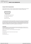
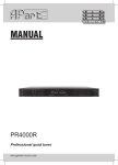
CONCEPT1 RS232 COMMUNICATION
Concept 1 RS-232 Communication
Communication with Concept 1 via RS-232 is done with simple ASCII Commands and Replies. The port settings are
19200Baud, 8bits, no parity and 1 stop bit. The physical connection is as described in the figure below:
Pin 2: TX data: data transmission output
Pin 3: RX data: data reception input
Pin 5: GND: ground
Other pins are not used.
An instruction has at least a command and an attribute. In many cases, there are extra values needed, like a zone
or a value. Please make sure that you’re familiar with the 3 modes (stereo, 2 zone linked and 2 zone unlinked) of
the Concept 1 because in some commands, there needs to be a zone specified depending on the mode. From
here we assume that the 3 modes are clear and understood. If not, please read the user manual first. Instructions
always have to be ended with <CR>, carriage return. Line feed <LF> characters will always be omitted, however
Concept 1 can use (and echo) <LF> after a <CR>. Instructions are not case sensitive!
Commands
The 4 possible commands are: SET, GET, INC and DEC. With the INC and DEC command, a “step value” can be
specified. This needs to be a positive number between 1 and 10. A step value bigger than 10, will be set to 10. If
no value is specified, default value 1 will be used.
Example: the music volume is -50 and the following instruction will be given:
INC MSCLVL<CR>
The music level now will be -49. Now the next instruction is given:
DEC MSCLVL 8<CR>
The music level now is -57.
WWW.APART-AUDIO.COM
[email protected]
CONCEPT1 RS232 COMMUNICATION
Overview of Attributes
Attribute
MULTIZONE
ZONELINK
MSCLVL
MICLVL
MAXMSCLVL
MAXMICLVL
SELECT
EQBASS
EQTREB
STANDBY
AUTOLD
PAGACT
IPGAIN
ECHO
LF
BS
HEADER
VALFB
INFO
SOURCENAME
SERIAL
HWVRSN
SWVRSN
RESTORE
Description
Commands
Zone
Value*
Multi Zone
Zone Link
GET, SET
No
Binary
Music Level
Microphone Level
Maximum Music Level
Maximum Mic. Level
GET, SET,
INC, DEC
2
GET, SET
No
A, B, C
or D
Equalizer Bass
Equalizer Treble
GET, SET
No
No
-14 to 14
Standby
GET, SET
No
Binary
Auto Loudness
Paging Active
Input Gain
GET, SET
Source Selection
1
OFF (-80)
-79 to 0
GET, SET
No
2
No
-20 to 14
Echo
Line feed
Back Space
Header
GET, SET
No
Binary
Value Feedback
Info
GET, SET
GET
No
Binary
/
Source Name
GET, SET
No
<String>
Serial Number
Hardware Version Number
Software Version Number
GET
No
/
Restore Factory Settings
SET
No
Binary
Binary
* The column “Value” describes what range of values need to be given with the SET command
Value “Binary” can be OFF / ON or 0 / 1
Mode
The mode of Concept 1 is determined by MULTIZONE and ZONELINK. If MULTIZONE is OFF, the amplifier is working
in stereo mode. If MULTIZONE is ON, the amplifier will work in 2 zone mode. If ZONELINK is ON, the music level
of zone 1 and zone 2 are linked. Otherwise, when ZONELINK is OFF, the 2 zones have a separate volume setting.
Since these 2 commands change the behavior of the amplifier, it’s recommended only to change them when
the amplifier is not in action (no music present, volume at minimum). If the amplifier needs to be configured in
another mode, these are the first settings that need to be changed
WWW.APART-AUDIO.COM
[email protected]
CONCEPT1 RS232 COMMUNICATION
Operating Settings
MSCLVL is the music level. It can be OFF or a value between -79 and 0. If set at -80, it will be ”OFF”. If both
MULTIZONE and ZONELINK are ON, the corresponding zone needs to be specified.
MICLVL is the microphone level. It can be OFF or a value between -79 and 0. If set at -80, it will be ”OFF”. If
MULTIZONE is ON, the corresponding zone needs to be specified.
MAXMSCLVL is the maximum music level. If the music level is adjusted above the maximum, it will be changed to
the maximum value. In case both MULTIZONE and ZONELINK are ON, there still are 2 different values possible for
zone 1 and zone 2. The difference between those 2 levels will determine the offset between the volumes of both
zones. The maximum difference in this mode is 40. Example:
SET MAXMSCLVL ZONE1 -16<CR>
SET MAXMSCLVL ZONE2 -10<CR>
Now, the volume can be adjusted between OFF and -10. The level in zone 1 will always be 6 dB lower than the level
in zone 2.
MAXMICLVL is the maximum microphone level. If the microphone level is adjusted above the maximum, it will be
changed to the maximum value.
SELECT is the source selection. The source selection in both zones is always the same, so it’s never needed to
specify the zone
Equalizer
Also the equalizer settings are the same for both zones.
EQBASS sets the level of the bass.
EQTREB sets the level of the treble.
The value must be between -14 and 14 in steps of 2. If a different value is used, it will get changed to the closest
match.
Configuration Settings
AUTOLD is Auto Loudness and this is only active in Stereo mode. It will adjust the equalizer depending of the
volume setting. If the auto loudness is on, the sound will still be more “rich” at low levels.
PAGACT is paging active. If set on, the microphone will only be on when there is a contact between pin A or B and
the ground of the connector at the backside of the amplifier (see user manual). In that case, the music will be
muted as well. The Concept 1 will also send ”PAGING (ZONEx) ON/OFF<CR>” when the contacts are closed/opened
so the user can know the status.
IPGAIN is input gain. Each source input has its own gain setting so the source (A, B, C or D) needs to be specified.
The value can be between -20 and 14 in steps of 2. If an invalid value is used or no source is specified, “ERROR:
Value Invalid!<CR>” will be replied. Otherwise, the reply will be “Command Exicuted!<CR>”
ZONESPLIT is only used in MULTIZONE mode. Default, the zone split value is off, which means that left and right of
the sources will be mono summed in MULTIZONE mode. Some users would like to have a different music in each
zone by plugging different sources for left and right. By setting ZONESPLIT on, the left input will be sent to zone1
and right input to zone 2, like in stereo mode. This way, it’s possible to have different music in each zone but please
note that the source select will always impact both zones. The ZONESPLIT feature is implemented starting from
V1.0.2
WWW.APART-AUDIO.COM
[email protected]
CONCEPT1 RS232 COMMUNICATION
RS-232 Settings
All RS-232 settings are binary values, they can be ON or OFF.
If ECHO is on, all received characters are echoed back. This can be handy when programs like hyperterminal are
used.
LF is Line Feed. Line feed is an ASCII character (0x0A) which is sometimes used to let the cursor jump to the next
line. Concept 1 always omits the line feed character. However, when LF is on, there will be put <LF> character
behind each <CR> character. This is both the case for echoing as for messages send by Concept 1. Please take a
look to following example: in both cases, the user sends the following string: “get msclvl<CR>”.
With ECHO on and LF off, this will be returned by Concept1:
“get msclvl<CR>”
“MSCLVL -16<CR>”
In case both ECHO and LF are on, it will be like this:
“get msclvl<CR><LF>”
“MSCLVL -16<CR><LF>”
BS is Back Space. This is also an ASCII character. In case BS and ECHO is on, Concept 1 will reply <BS><SP><BS> each
time when a <BS> is received. <SP> is the space character. This setting is only intended to have a “nice” text when
used with programs like Hyperterminal.
With HEADER on, each string, both incoming as outgoing, has to start with “>” (ASCII character 0x3E) as header
of the string. This function works only when ECHO is OFF! Please note that for the first replies after start up, this
function will not work correctly. The reason for this is that the settings are loaded later. Anyway, this shouldn’t be
a problem. If ECHO and LF are put off and HEADER is put on, each string will start with “>” (ASCII character 0x3E)
and each string will end with <CR> (ASCII character 0x0D). This can help in making the string handling easier. Please
don’t forget that also instructions will have to begin with “> “ in this case! Example (with MULTIZONE and VALFB
ON):
Instruction:
>SET MICLVL ZONE1 -35<CR>
Reply:
>MICLVL ZONE1 -35<CR>
WWW.APART-AUDIO.COM
[email protected]
CONCEPT1 RS232 COMMUNICATION
Status Update
VALFB stands for Value Feed Back. When this setting is on, all value changes are sent “autonomously” by Concept
1. This way it’s easy to keep the status synced. Default, VALFB is on. IPGAIN and SOURCENAME are NOT sent when
they are modified.
INFO can only be used with the GET command. The GET INFO instruction is replied with the current status of most
variables. It will only work when VALFB is on. IPGAIN and SOURCENAME is not sent after the GET INFO instruction
but their status can also be requested with the GET command. Below is an example of a reply after a GET INFO
instruction in stereo mode. The <CR> characters at the end of the line are not shown:
PAGING OFF
MULTIZONE OFF
PAGACT ON
AUTOLD ON
SELECT A
MSCLVL OFF
MICLVL OFF
MAXMSCLVL 0
MAXMICLVL 0
EQBASS 0
EQTREB 0
Source Name
With SOURCENAME, it’s possible to change or read the source name that’s shown on the display of the Concept
1. There always has to be a source (A, B, C or D) specified. The source name string itself is case sensitive and may
contain space characters. Example:
Instruction:
get sourcename a<CR>
Reply:
Source A<CR>
Instruction:
set sourcename a BGM3000<CR>
Reply:
Command Executed!<CR>
Instruction:
get sourcename a<CR>
Reply:
BGM3000<CR>
Version information
The following attributes will only work with the GET command:
SERIAL will return the serial number, a 4 digit hex number. In case it’s not programmed, it will return “Not Yet
Implemented!<CR>”.
HWVRSN will return the hardware version number
SWVRSN will return the hardware version number
WWW.APART-AUDIO.COM
[email protected]
CONCEPT1 RS232 COMMUNICATION
Restore Factory Settings
The factory settings can be restored with the following instruction: “SET RESTORE ON<CR>”. The Concept1 will
reply with “Please Cycle Power!<CR>”, the output will be muted and the display will show “RESET”. The user must
power off and power on the amplifier. During power on, the factory settings will be restored.
Standby
The amplifier can be set in Standby mode with the (optional) IR remote control or with the SET STANDBY ON
instruction. Leaving Standby mode can also be done with IR remote controller or the SET STANDBY OFF instruction.
If an RS-232 instruction is given when the amplifier is in Standby mode or during power on and the amplifier is not
ready, it will answer with “STANDBY ON”. Please wait until the amplifier is operational.
Power down
During power down, all settings are stored in the memory of Concept1. After this, a string “POWER DOWN!<CR>”
will be send. Depending on how much variables that need to be stored, possible, there is not enough time to send
this complete string.
Errors
The following error strings may be sent by Concept1:
ERROR: Command Unknown!<CR>
character.
: Wrong spelling of command or command started with Back Space
ERROR: Unknown Attribute! <CR>
: Wrong spelling of attribute.
ERROR: No Header! <CR>
with header. See “RS-232 Settings”.
: When HEADER is on and ECHO is off, each instruction must be started
ERROR: Unknown Instruction! <CR>
SET SERIAL 0001<CR>
: A command was used with an attribute that does not support this. E.g.
ERROR: Value Invalid! <CR>
: A value was out of range or illegal.
ERROR: Zone Invalid! <CR>
: No valid zone was specified. Valid zone names are ZONE1 and ZONE2,
without space between ZONE and its number.
ERROR: AMPLIFIER PROTECT! <CR>
: See user manual (or appendix)
ERROR: OVER TEMPERATURE! <CR>
: See user manual
Appendix
The instructions SET IPGAIN … and SET SOURCENAME … will write a value to the internal memory of the Concept1.
When these instructions are given, please wait for the reply or put a delay of at least 100ms after this instruction.
The amplifiers with Hardware Version number ACPT 1V04 could possible send “ERROR: AMPLIFIER PROTECT!<CR>”
when they are powered off. This is because the sense circuit of the amplifier reacts very fast. This doesn’t mean
there is something wrong with the amplifier.
WWW.APART-AUDIO.COM
[email protected]