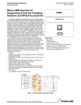
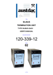
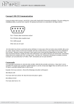
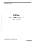
1
Title
4 CHANNEL DIGITAL
RECEIVER
TYPE SILBUS-RX4D
USER'S MANUAL
Document Number
120-248-12
Issue
04
1 OF 31
REVISION CONTROL
04
Minor Corrections
2014.06.26
PB'
CG
PC
03
Add configuration upload and
download. Add low and high
power relay contact variants
Add NAND NOR FLIP functions
2010.11.12
PB’
PB’
JY
02
Fix specs, add prog info
2010.02.02
PB’
PB’
JY
01
Original
2009.02.10
PB’
PB’
JY
Issue
Details
Date
Written
Designed
Approved
Austdac Pty Ltd
Unit 1 / 4 Packard Avenue
Castle Hill NSW 2154
Australia
PO Box 6486
Baulkham Hills Business Centre
NSW 2153
Australia
Phone: + 61 2 8851 5000
Fax: + 61 2 9899 2490
Website: www.austdac.com.au
Austdac Inc.
455 Lowries Run Rd,
Pittsburgh, PA 15237
USA
Phone: +1 888 254 9155
Fax: +1 412 635 0179
Copyright 2010-11-12
This document remains the property of Austdac Pty. Ltd. It is subject to its recall and must not be
reproduced in part or whole or its contents divulged to third parties without prior written approval
from Austdac Pty Ltd.
4 CHANNEL DIGITAL RECEIVER
TYPE SILBUS-RX4D USER'S MANUAL
2 OF 31
120-248-12
Issue: 04
TABLE OF CONTENTS
REVISION CONTROL .................................................................................................................... 2
TABLE OF CONTENTS .................................................................................................................. 3
PHOTOGRAPHS ............................................................................................................................ 4
TABLES .......................................................................................................................................... 4
FIGURES ........................................................................................................................................ 4
1 GENERAL DESCRIPTION .......................................................................................................... 5
2 FRONT PANEL LAYOUT ............................................................................................................. 5
3 THEORY OF OPERATION .......................................................................................................... 7
3.1 LOGIC FUNCTIONS ............................................................................................................. 7
3.2 THE FLIP FUNCTION ........................................................................................................... 9
3.3 OUTPUT RELAY SWITCHING POWER ............................................................................. 10
4 OPERATING INSTRUCTIONS .................................................................................................. 11
5 CONFIGURATION ..................................................................................................................... 11
5.1 CONSOLE PORT OPERATION .......................................................................................... 12
5.2 help COMMAND ................................................................................................................. 12
5.3 REPEAT COMMAND .......................................................................................................... 13
5.4 VERSION COMMAND ........................................................................................................ 14
5.5 STACK COMMAND ............................................................................................................ 14
5.6 SILBUS MAP COMMAND ................................................................................................... 14
5.7 SILBUS STATUS COMMAND............................................................................................. 15
5.8 SILBUS GET COMMAND ................................................................................................... 15
5.9 LOGIC COMMAND ............................................................................................................. 16
5.10 ADD COMMAND ............................................................................................................... 16
5.11 DELETE COMMAND ........................................................................................................ 17
5.12 SBOUT COMMAND .......................................................................................................... 18
5.13 SSYNC COMMAND .......................................................................................................... 19
5.14 ONFLT COMMAND........................................................................................................... 20
5.15 OFFFLT COMMAND ......................................................................................................... 20
5.16 DISPLAY COMMAND ....................................................................................................... 21
5.17 UPLOAD CONFIGURATION COMMAND ......................................................................... 22
5.18 DOWNLOAD CONFIGURATION COMMAND ................................................................... 23
5.19 CONFIGURATION RECORDS.......................................................................................... 25
6 TERMINATIONS AND CONNECTIONS .................................................................................... 26
6.1 RELAY OUTPUT PORTS ................................................................................................... 26
6.2 POWER INPUT PORT ........................................................................................................ 27
6.3 SILBUS NETWORK PORT ................................................................................................. 27
7 CERTIFICATION ....................................................................................................................... 27
7.1 INSTALLATION CONFIGURATION 1 ................................................................................. 28
7.2 INSTALLATION CONFIGURATION 2 ................................................................................. 29
8 SOFTWARE REVISION AND DISPLAY .................................................................................... 30
9 SPECIFICATIONS ..................................................................................................................... 31
4 CHANNEL DIGITAL RECEIVER
TYPE SILBUS-RX4D USER'S MANUAL
3 OF 31
120-248-12
Issue: 04
PHOTOGRAPHS
Photograph 1 SILBUS-RX4D front panel ........................................................................................ 6
Photograph 2 Access to console port and programming switch ...................................................... 6
Photograph 3 Laptop connected to console port via MEAN1 interface .......................................... 12
Photograph 4 Hyper Terminal delay setup .................................................................................... 24
TABLES
Table 1 SILBUS-RX4D switching capabilities................................................................................ 10
Table 2 Status LED flash sequence meanings .............................................................................. 11
Table 3 SILBUS-RX4D Configuration record................................................................................. 25
Table 4 Digital input termination details......................................................................................... 26
Table 5 Power input port termination details ................................................................................. 27
Table 6 SILBUS network port termination details .......................................................................... 27
FIGURES
Figure 1 Multi-term logic function .................................................................................................... 7
Figure 2 S-AND logic function and resolver cascading .................................................................... 8
Figure 3 FLIP logic Function ........................................................................................................... 9
Figure 4 SIBUS-RX4D Connection diagram .................................................................................. 26
Figure 5 SILBUS-RX4D segregation and isolation levels .............................................................. 27
Figure 6 Installation configuration 1 .............................................................................................. 28
Figure 7 Installation configuration 2 .............................................................................................. 29
4 CHANNEL DIGITAL RECEIVER
TYPE SILBUS-RX4D USER'S MANUAL
4 OF 31
120-248-12
Issue: 04
1 GENERAL DESCRIPTION
The four channel digital receiver is part of a family of explosion protected DIN rail mounting
modules that transmit to and receive from an Austdac SILBUS field bus network. The
SILBUS-RX4D can receive from just a few through to many digital ON/OFF signal from a
SILBUS network to control the four relay outputs directly or via complex multi-term logic
functions. The digital receiver has four output relays controlled by up to six logic resolvers
capable of implementing OR, AND, NOR, NAND, FLIP and S-AND logic functions. Each
resolver has an independently configurable output ON and OFF delay filter to allow
implementation of simple timer functions.
The four digital outputs are galvanically isolated from each other, from the power supply
port and the SILBUS network port. This isolation allows the SILBUS-RX4D to provide many
simple and highly effective solutions when used in installations involving intrinsically safe
and non-intrinsically safe circuits.
The four channel digital receiver is available in two output contact power switching variants
to cover all applications of the receiver. The two variants are the SILBUS-RX4D-L for low
power switching applications and the SILBUS-RX4D-H for high power switching
applications. See the specifications section for actual switching capacities. For the
remainder of the manual the generic SILBUS-RX4D will be used instead of two individual
types.
The receiver is housed within a DIN rail mounting enclosure measuring 100mm (W) x
75mm (H) x 110mm (D). The front panel is located between the two top of enclosure
mounted terminal blocks to provide a clear view of the operation indicating LED’s. Four
LED’s, one for each channel, are provided to indicate the status of each of the output
relays. A further two LED’s are provided to show power and SILBUS network status.
The SILBUS-RX4D can be quickly and simply configured using a laptop computer running
Hyper Terminal and a small plug in programming adaptor. Each digital output can be
independently programmed to any SILBUS channel address. Each digital input can also
have it’s de-bounce timer independently programmed between 500ms and 10s in 100ms
increments.
2 FRONT PANEL LAYOUT
The four channel digital receiver front panel is located between the terminal blocks that
form part of the enclosure. Located in the top right hand corner of the front panel are the
STATUS and POWER indication LED’s. The green power LED is illuminated whenever a
12 volt supply is connected to the receiver. The yellow status LED flashes at different rates
to indicate the operational status of the receiver, see table 2 for more details.
On the lower left of the front panel are four green LED’s labelled from one through to four,
these LED’s indicate the status of the four digital relay outputs. A LED is illuminated to
indicate an on or active output and extinguished to indicate an off or inactive output.
The front panel is shown in photograph 1.
4 CHANNEL DIGITAL RECEIVER
TYPE SILBUS-RX4D USER'S MANUAL
5 OF 31
120-248-12
Issue: 04
The front panel can be snapped out and removed by using a wide bladed flat screw driver
to gain access to the configuration (console) port and programming switch. Photograph 2
below shows the front panel removed and the location of the console port and programming
switch.
Photograph 1 SILBUS-RX4D front panel
Photograph 2 Access to console port and programming switch
4 CHANNEL DIGITAL RECEIVER
TYPE SILBUS-RX4D USER'S MANUAL
6 OF 31
120-248-12
Issue: 04
The black four pin console port connector and the red programming switch are located
behind the lower right corner of the front panel label.
3 THEORY OF OPERATION
3.1 LOGIC FUNCTIONS
The four channel digital receiver has been furnished with six configurable multi-term logic
gates or logic resolvers, four of which drive the four general purpose relay outputs. These
logic resolvers are typically used to implement conveyor ‘OR’ and ‘AND’ functions for
emergency stop or remote isolation. The six basic logic functions are ‘OR’, ‘AND’, ‘NAND’,
‘NOR’, ‘FLIP’ and ‘S-AND’ while ‘S-NAND’ is possible by inverting the input terms. ‘S-AND’
and ‘S-NAND’ allow the two bit safety channels to be used as a single term in the logic
resolver.
COMMON DATABASE
A1
B7
D4
M1
P8
G2
LOGIC RESOLVER
A2
RELAY
FILTER
ON: 0.5 Sec
OFF: 3.0 Sec
DRIVE
H6
J3
Figure 1 Multi-term logic function
Each logic resolver has a maximum number of input terms equal to the size of the
connected SILBUS network or system database i.e. 128, 64, 32, 16 or 8. The input terms
can be specified in any order and do not need to be sequential. Channels assigned for
analink, fastlink, datalink or sync transmission should not be used as input terms of the
logic functions, otherwise unpredictable results will be obtained.
The output of the logic resolver is fed via a filter with independently variable on and off filter
periods before being applied to the relay output. The on and off filter times can be
independently configured from 100mS to hours in 100mS steps. The filter on and off times
are used to stop intermittent signals from causing inadvertent trips and alarms. The filter on
time ensures that the output from the logic resolver must be on for the ‘on’ filter period
before the relay output will be asserted. The filter off time ensures that the output from the
logic resolver must be off for the ‘off’ filter period before the relay output will be negated.
The timers can be used to implement simple timer related functions when delays are
needed in system control sequences.
The filtered logic resolver output can be transmitted back onto the SILBUS network for use
in further logic operations and to be read by the network channel generator or by a test unit
4 CHANNEL DIGITAL RECEIVER
TYPE SILBUS-RX4D USER'S MANUAL
7 OF 31
120-248-12
Issue: 04
for indication purposes. Figure 1 shows the layout of one of the first four logic resolvers (1,
2, 3 and 4) that have the capability to drive an output relay. The SILBUS-RX4D has a
further two logic resolvers (5 and 6) that do not have output relays but otherwise function
identically. These two logic resolvers can be used to implement multi-term logic functions
and then provide a single output that is feed back for use as an input term of one of the
other logic resolvers. This is useful when combining safety channels and normal digital
channels in the same logic function, as the S-AND function and the standard AND/OR
functions can not be handled by the one logic resolver.
By combining logic and timer functions simple RS type latch functions can also be
implemented by the SILBUS-RX4D. The logic resolver functions and outputs are only
updated during the SILBUS SYNC pulse period at the end of each SILBUS scan period.
System designers should take this and the associated delays into account when
implementing and configuring the logic resolvers.
If the relay output is required to be operated from a single SILBUS channel then a singleterm ‘AND’ or ‘OR’ logic function should be implemented.
The ‘S-AND’ safety function is used with safety channels and not only takes into account
the status of the safety channel but also includes the quality or validity of the safety channel
in the logic function. The ‘S-AND’ logic function can only accept safety channel input terms,
the inclusion of standard digital channels as input terms will result in unpredictable outputs
from the ‘S-AND’ logic function. The ‘S-AND’ logic function also needs to know the safety
sync channel address, typically A1 as shown in figure 2. Safety and standard digital
channels can be combined in logic operations by cascading logic resolvers as shown in the
following figure.
SAFETY SYNC CHANNEL
A1
A3
A5
A7
B3
B5
SAFETY SYNC CHANNEL ADDRESS = A1.
SAFETY SYNC CHANNEL IS REQUIRED BY S-AND FUNCTION
BUT IS NOT CONSIDERED AN INPUT TERM.
LOGIC
RESOLVER 1
S-AND
COMMON DATABASE
RELAY 1
FILTER
ON: 0.2 Sec
OFF: 0.9 Sec
DRIVE
M1
M2
M3
P8
J4
LOGIC
RESOLVER 2
OR
C4
RELAY 2
FILTER
ON: 1.5 Sec
OFF: 2.1 Sec
DRIVE
G4
CHANNEL C4 IS USED AS A METHOD OF CASCADING ONE LOGIC RESOLVER TO ANOTHER.
CHANNEL C4 CAN'T BE USED BY ANY FIELD TRANSMITTER AND CAN'T BE MODIFIED VIA THE MODBUS INTERFACE
Figure 2 S-AND logic function and resolver cascading
When logic resolver outputs are fed back onto the SILBUS network for inclusion in
subsequent logic resolvers the designer should ensure that these feedback channels are
not modified by field devices or the channel generator.
4 CHANNEL DIGITAL RECEIVER
TYPE SILBUS-RX4D USER'S MANUAL
8 OF 31
120-248-12
Issue: 04
The configuration and use of these logic resolvers is further explained in the configuration
section of this manual.
3.2 THE FLIP FUNCTION
The FLIP logic function implements a D type flip flop with feedback to produce a toggling
‘flip’ function which is useful in implementing single way road block light systems. A
schematic of the FLIP function is shown in the figure below.
COMMON DAT ABASE
LOGIC RESOLVER 1
Vcc
1. J3 IS T HE ENTRY SWITCH / TRANSMITT ER TO SINGLE WAY ROAD
2. REQUIRE A J3 T RANSMIT TER AT EACH END OF SINGLE WAY ROAD
3. K6 USED T O DRIVE RECEIVER AT FAR END OF SINGLE WAY ROAD
4. ON POWER UP RESOLVER / RELAY 1 IS DE-ENERGISED = RED LIGHT
5. EACH T IME J3 IS ASSERT ED THE FLIP FLOP WILL T OGGLE
6. T HE TOGGLE ONLY OCCURS DURING THE DUPLINE SYNC PULSE
SET
Q
FUNCTION
FLIP
J3
INPUT T ERM
CLK
'D' T YPE
FLIP FLOP
D
RELAY
Q
OUT PUT
FILT ER
ON: 0.2 Sec
OFF: 2.2 Sec
DRIVE
RESET
POWER RESET
K6
OUT PUT TERM
Figure 3 FLIP logic Function
The FLIP function occupies one logic resolver and has one configurable input term and one
configurable output term. The FLIP function also uses the SILBUS-RX4D power on reset
signal in its operation, this does not need to be configured it is automatically assigned when
the FLIP function is selected.
During the SILBUS SYNC pulse period the FLIP function looks for the input term (J3) to be
asserted (turned on) during the last SILBUS scan period and if so will toggle the ‘D’ type flip
flop which results in the logic resolver output (K6) being changed to its opposite state i.e. if
it was off it is now on or if it was on it is now off. The output relay can be used to drive a set
of traffic lights to control the single way road. The output term is also sent back onto the
SILBUS network so that a digital receiver with a single term AND function can be used to
control the traffic lights at the remote end of single way road. A digital transmitter configured
to J3 and located at either end of the single way road is used to control the block light
system.
If the input term (J3) is held on or asserted over many SILBUS scan periods the flip flop of
the FLIP function will not continue to toggle, the clock input to the ‘D’ type flip flop is edge
sensitive and requires the input term to be negated and then asserted again before another
toggle will take place.
The power on reset signal ensures that the ‘D’ type flip flop of the FLIP function comes up
in a known state i.e. the output term is not on or asserted (green light). By combining other
logic resolvers with the FLIP function more sophisticated control systems can be
implemented.
4 CHANNEL DIGITAL RECEIVER
TYPE SILBUS-RX4D USER'S MANUAL
9 OF 31
120-248-12
Issue: 04
3.3 OUTPUT RELAY SWITCHING POWER
The SILBUS-RX4D is available in two versions that have different relay contact switching
capabilities. The SILBUS-RX4D-L variant for low power switching capabilities and the
SILBUS-RX4D-H variant for high power and high voltage switching capabilities.
The table below shows the differences between the two models.
SILBUS-RX4D SWITCHING POWERS
PARAMETER
SILBUS-RX4D-L
Pm
25W
Pi
25W
Um
25V
Ui
25V
Ii
1A
Minimum switching voltage
1V
Minimum switching current
10uA
Minimum switching power
10uW
Contact material
Rhodium
SILBUS-RX4D-H
100W
100W
250V
25V
3A
12V
250mA
3W
Tungsten
Table 1 SILBUS-RX4D switching capabilities
The SILBUS-RX4D-H is only recommended for use where powers higher than 3 watts,
voltages greater than 12V and currents greater than 250mA are being switched. The
SILBUS-RX4D-H was specifically designed for use in the US market where 110V
contactors are being switched directly by the SILBUS-RX4D-H.
The SILBUS-RX4D-H is not recommended for use in Australian installations where low
touch potential regulations are in place. The SILBUS-RX4D-L is designed for use in a
hazardous area where intrinsically safe circuits or extra low voltage control signals are
being switched.
The SILBUS-RX4D-H can be used in Australian installations provided that the minimum
switching requirements and touch potential issues are dealt with satisfactorily.
Operating the SILBUS-RX4D-H below the specified minimum switching requirements
will result in intermittent and unreliable operation of the output relay contacts.
Similarly, operating the SILBUS-RX4D-L above its maximum switching capabilities will also
result in unreliable operation of the output relay contacts and possibly result in welded or
open-circuit contacts.
4 CHANNEL DIGITAL RECEIVER
TYPE SILBUS-RX4D USER'S MANUAL
10 OF 31
120-248-12
Issue: 04
4 OPERATING INSTRUCTIONS
The four channel digital receiver does not require any operator action to operate once it has
been installed within an IP54 host enclosure and configured correctly.
An understanding of the various flash sequences of the yellow status LED may be required
to help in the trouble shooting and maintenance of the entire SILBUS network installation.
The status LED provides information on the operational status of the receiver and the
connected SILBUS network. This information includes correct microprocessor operation,
health of connected SILBUS network, selection of an invalid SILBUS channel address and
indication of software version number. The table below shows the various flash sequences
and their meaning.
FLASH SEQUENCE
NONE – LED ON OR
OFF CONTINUOUSLY
OFF CONTINUOUSLY
1 SECOND ON
1 SECOND OFF
LONG PERIOD OFF
FOLLOWED BY 3
SHORT FLASHES
MAJOR REVISION
FLASH SEQUENCE –
PAUSE – MINOR
REVISION FLASH
SEQUENCE
STATUS LED FLASH SEQUENCES
NAME
MEANING
INTERNAL MICROPROCESSOR FAULT OR NO
NO FLASH
POWER
RECEIVER FUNCTIONING – NO SILBUS
NO FLASH
CONNECTED TO SILBUS PORT
RECEIVER FUNCTIONING – HEALTHY SILBUS
FAST FLASH
CONNECTED TO SILBUS PORT
ONE OR MORE LOGIC TERMS HAVE BEEN
PAUSE – 3
ASSIGNED TO AN INVALID SILBUS CHANNEL
SHORT
ADDRESS I.E. P8 FOR A 64 CHANNEL SILBUS
FLASH
NETWORK
SOFTWARE
VERSION
SEQUENCE
INDICATES THE SOFTWARE VERSION LEVEL
OCCURS IMMEDIATELY AFTER POWER UP. SEE
SOFTWARE REVISION SECTION OF THIS MANUAL
FOR DETAILS
Table 2 Status LED flash sequence meanings
The console port power source selection switch SW1 must always be in the run position for
correct operation of the receiver. The run position is with the small slide actuator pushed
furthest away from the black four pin console connector X111.
The front panel has four green LED’s numbered one to four that are illuminated whenever
the associated relay is energised.
5 CONFIGURATION
The four channel digital receiver has several operational parameters that require
configuration prior to use. All of these parameters can be viewed and changed via the
console port. The console port consists of a small four pin connector and a two position
slide switch behind the front panel label. Access to the console port can be gained by
snapping out the front panel using a wide bladed flat screw driver in one of the slots
between the front panel and terminal blocks.
To use the console port an Austdac MEAN1 interface, A to B USB cable and laptop
computer running Hyper Terminal are required.
For more detail on the console port, MEAN1 interface and their use refer to Austdac
document 53-018-12.
4 CHANNEL DIGITAL RECEIVER
TYPE SILBUS-RX4D USER'S MANUAL
11 OF 31
120-248-12
Issue: 04
5.1 CONSOLE PORT OPERATION
The console port should be connected to a laptop running a terminal emulation program
such as Hyper Terminal via the Austdac interface type MEAN1 and a USB cable as
shown in the following photograph.
Photograph 3 Laptop connected to console port via MEAN1 interface
The SILBUS-RX4D certification places restrictions on what may be connected to the
console port, the connection of an interface other than the Austdac MEAN1 to the console
port will invalidate the certification of the receiver.
The terminal emulation program should be configured to 19200 baud, 8 data bits, one
stop bit, no parity, no flow control and DEC VT100 terminal emulation.
Once communications have been established with the SILBUS-RX4D, it will display a
screen of information that includes software version, software checksum, and a list of
commands followed by the console port prompt.
The prompt includes an abbreviation of the receiver type number. RX4D::>
Commands are invoked by entering the command name followed by any optional
modifiers, keywords and the “ENTER” key. The enter key is shown in the following
examples as a “ ” symbol.
5.2 HELP COMMAND
The HELP command prints a list of all available commands and shows the syntax for each
command. Optional command modifiers are shown within [ ] while mandatory modifiers
are shown within < >. An example of a screen output follows:
RX4D::>HELP
4 CHANNEL DIGITAL RECEIVER
TYPE SILBUS-RX4D USER'S MANUAL
12 OF 31
120-248-12
Issue: 04
Software 1V04 0xCBF0 Configuration 0x049D SN:09041000
Commands:
--------------------------------------------------------------------------------********** Level 1: Standard Menu **********
HELP
[1…7] Level of Help
Display Help Menu
REPEAT
[LF] [Refresh rate in seconds]
Repeat Previous Command
VER
Firmware Version and Checksum
STACK
Display Peak Stack Usage
SBMAP
Display SILBUS I/O Map
SBSTAT
Display SILBUS Status
SBGET
<A1–P8>
Display a SILBUS Channel State
SSYNC
[<SET> <Safety Sync Address>]
Select safety sync address
LOGIC
<SET> <RELAY> <OFF | N/AND | N/OR | SAND | FLIP>
Select logic function
ADD
<SET> <RELAY> <Term | !Term | Term#>
Add terms to relay
DEL
<SET> <RELAY> <Term | !Term | Term#>
Delete terms from relay
SBOUT
<SET> <RELAY> <SILBUS Address>
Select relay O/P address
ONFLT
[<SET> <RELAY> <On time in mS>]
Set on filter time
OFFFLT [<SET> <RELAY> <Off time in mS>]
Set off filter time
DISP
[<RELAY> <Text | Map>]
Display relay logic function
CFGUP
Upload Configuration Text
CFGDWN
Download Configuration Text
------------------------------------------------------------------RX4D::>_
5.3 REPEAT COMMAND
The REPEAT command is used after another command to continuously repeat that
command. As an example the SBGET command can be executed followed by the
REPEAT command to provide a continuously updating display of the selected SILBUS
channel. The display will continue to update until any key is hit. The SILBUS-RX4D will
respond by displaying the prompt.
RX4D::>SBGET D1
D1 = ON
RX4D::>REPEAT
D1 = OFF
RX4D::>_
In the above example the “OFF” changed to an “ON” whenever SILBUS channel D1 was
activated. In this mode the repeat command writes over the previously displayed
information, if required, the repeat command can be made to refresh the information on a
new line by entering LF (line feed) as part of the command invocation. The repeat
command refreshes the display every one second by default. The refresh rate can be
slowed by entering the refresh rate in seconds as part of the repeat command as shown in
the following command:
RX4D::>REPEAT LF 5
D1 = OFF
D1 = OFF
D1 = ON
4 CHANNEL DIGITAL RECEIVER
TYPE SILBUS-RX4D USER'S MANUAL
13 OF 31
120-248-12
Issue: 04
D1
D1
D1
D1
=
=
=
=
OFF
OFF
ON
OFF
RX4D::>_
As can be seen from the above example the repeat command refreshed the status of
SILBUS channel D1 on a new line every five seconds. In the LF mode a record of the
status of D1 can be viewed on the screen.
5.4 VERSION COMMAND
The VERSION command is used to display the serial number, abbreviated type number,
software version and program memory checksum of the SILBUS-RX4D. The command
can be invoked as shown in the following example:
RX4D::>VER
SN:09124321 RX4D 1V01 0XB12F
RX4D::>_
This command is useful when the user needs to know the software version or serial
number. The program memory checksum is useful to confirm that a software update has
completed successfully without any programming errors.
5.5 STACK COMMAND
The STACK command is provided to allow the technician to gauge the health of the
SILBUS-RX4D microprocessor and its code by displaying the maximum usage of the
program stack. The display is a peak value of the stack usage since the SILBUS-RX4D
was powered up. The command can be invoked as shown in the example below:
RX4D::>STACK
Stack usage/size = 312/1024
Percentage Used = 30%
RX4D::>_
This command would typically only be used when requested by an Austdac software
engineer.
5.6 SILBUS MAP COMMAND
The SILBUS map command allows the operator to obtain a snapshot of the SILBUS
network to which the receiver is connected. The map shows all of the SILBUS channels
available on the network. The map consists of a table with a heading of groups below
which is displayed the channels using ones and zeros. Each group is shown vertically with
1 at the top and 8 at the bottom. A one indicates an ON channel and a zero indicates an
OFF channel. An example of an SBMAP is shown below with channels A4, P7 and P8 on
or active:
4 CHANNEL DIGITAL RECEIVER
TYPE SILBUS-RX4D USER'S MANUAL
14 OF 31
120-248-12
Issue: 04
RX4D::>SBMAP
ABCDEFGHIJKLMNOP
0000000000000000
0000000000000000
0000000000000000
1000000000000000
0000000000000000
0000000000000000
0000000000000001
0000000000000001
RX4D::>_
The SBMAP command is particularly useful when used with the repeat command as this
will display a continuously updated table.
5.7 SILBUS STATUS COMMAND
The SILBUS status command displays the number of SILBUS channels available on the
connected SILBUS network, a SILBUS synchronisation pulse count and a SILBUS error
count. This command is used to determine if the connected SILBUS network is functioning
correctly and how many channels are available. The error count should typically be zero
while the sync count should be incrementing. Once again the use of the repeat command
will provide a dynamic updating display. An example of the SBSTAT command follows:
RX4D::>SBSTAT
No. Chan = 128, Sync Count = 17807, Error Count = 0
RX4D::>_
The error count will be non zero whenever the connected SILBUS network is out of
specification. The error count can be non zero if the connected SILBUS network channel
generator has its power supply cycled off and on. These error counts should be ignored.
5.8 SILBUS GET COMMAND
The SILBUS get command is used to display the status of one selected SILBUS channel
only. If this command is used in conjunction with the repeat command a continuously
updating display can be achieved. The command is invoked by entering the command
name followed by the desired channel address as shown in the two examples below:
RX4D::>SBGET M3
M3 = OFF
RX4D::>SBGET B7
B7 = ON
RX4D::>_
4 CHANNEL DIGITAL RECEIVER
TYPE SILBUS-RX4D USER'S MANUAL
15 OF 31
120-248-12
Issue: 04
5.9 LOGIC COMMAND
This command is used to display and configure the logic function type of the matrices
logic resolvers or output relays of the SILBUS-RX4D. The SILBUS-RX4D has six logic
resolvers, matrices or relays but only the first four are fitted with actual output relays. The
valid logic functions are OR, NOR, AND, NAND, FLIP, SAND and OFF. The current logic
type of the output relays can be displayed by simply entering the command name as
shown in the example below:
RX4D::>LOGIC
Relay Matrix[1]
Relay Matrix[2]
Relay Matrix[3]
Relay Matrix[4]
Relay Matrix[5]
Relay Matrix[6]
is
is
is
is
is
is
FLIP
AND
OR
OFF
SAND
FLIP
RX4D::>_
If the command name is entered with additional attributes the logic function can be
configured to any of the valid logic types i.e. AND, NAND, FLIP, OFF, OR, NOR, SAND.
An example of configuring relay 1 is shown below:
RX4D::>LOGIC SET 1 AND
Matrix logic changed
Relay Matrix[1] is AND
Relay Matrix[2] is AND
Relay Matrix[3] is OR
Relay Matrix[4] is OFF
Relay Matrix[5] is SAND
Relay Matrix[6] is OFF
RX4D::>_
5.10 ADD COMMAND
This command is used to configure the specified logic resolver, matrix or output relay by
allowing terms to be added to the logic function. The terms are in the form of valid SILBUS
channel addresses and groups. Terms may also be inverted to allow negative logic to be
used. The add command does not display current logic resolver configuration. See the
DISP command for information on displaying the current configuration. Examples of
adding terms to logic matrix 3 using the ADD command are shown below:
RX4D::>ADD SET 3 B1
Matrix terms added
Relay Matrix[3] = B1
RX4D::>_
The first example shows the first term B1 being added to the matrix or resolver.
RX4D::>ADD SET 3 B2,B3
4 CHANNEL DIGITAL RECEIVER
TYPE SILBUS-RX4D USER'S MANUAL
16 OF 31
120-248-12
Issue: 04
Matrix terms added
Relay Matrix[3] = B1+B2+B3
RX4D::>_
The second example shows two terms B2 and B3, delimitated by a comma, being added
to the matrix or resolver. Valid delimiters are space, comma, plus and asterisk. The
delimiters are not significant when entering terms i.e. + does not force an OR function and
* does not force an AND function. The logic function is determined when using the LOGIC
command. The + and * are allowed to increase readability.
However when the terms are being displayed after the ADD command has been invoked
the + and * are significant i.e. + indicates an OR while an * indicates an AND function.
RX4D::>ADD SET 3 B4+!B5,B6+B7
Matrix terms added
Relay Matrix[3] = B1+B2+B3+B4+!B5+B6+B7
RX4D::>_
The third example shows four terms B4, B5, B6 and B7 being added to the matrix or
resolver. The B5 term is preceded by an exclamation mark to indicate inverted logic or a
NOT. Therefore the logic function will be true only when B5 is inverted or negated.
RX4D::>ADD SET 3 C#
Matrix terms added
Relay Matrix[3] = B1+B2+B3+B4+!B5+B6+B7+C#
RX4D::>_
The last example shows what appears to be a single term but is in fact the entire SILBUS
C group (eight terms). The SILBUS group is represented by the # character. The FLIP
function can only have one term for its input.
5.11 DELETE COMMAND
This command is used to configure the specified logic resolver, matrix or output relay by
allowing terms to be deleted from the logic function. The terms are in the form of valid
SILBUS channel addresses and groups. The delete command does not display current
logic resolver configuration. See the DISP command for information on displaying the
current configuration. Examples of deleting terms from logic matrix 4 using the DEL
command are shown below:
RX4D::>DEL SET 4 B7
Matrix terms deleted
Relay Matrix[4] = C#*D#*!E1*E2
RX4D::>_
The first example shows the term B7 being removed from the AND logic function of relay
four. Note that SILBUS groups C and D and channel E1 still remain in the logic function.
RX4D::>DEL SET 4 C1
Matrix terms deleted
Relay Matrix[4] = C2*C3*C4*C5*C6*C7*D#*!E1*E2
4 CHANNEL DIGITAL RECEIVER
TYPE SILBUS-RX4D USER'S MANUAL
17 OF 31
120-248-12
Issue: 04
RX4D::>_
The second example shows the term C1 being removed from the logic function. Note that
the SILBUS-RX4D converted the group term C# into the remaining seven individual terms.
RX4D::>DEL SET 4 C2*C3+C4,C5,C6*C7*D#
Matrix terms deleted
Relay Matrix[4] = !E1*E2
RX4D::>_
The third example shows the entire D group and the remaining terms of the C group being
removed from the logic function. Note the use of mixed delimiters.
RX4D::>DEL SET 4 E1
Matrix terms deleted
Relay Matrix[4] = E2
RX4D::>_
The last example shows the inverted logic term E1 being removed from the logic function.
Note that the exclamation mark is not entered when deleting inverted logic terms.
5.12 SBOUT COMMAND
This command is used to display and configure the SILBUS channel addresses of the six
logic resolver or matrix outputs. The current assigned relay output SILBUS channels can
be displayed by simply entering the command name as shown in the example below:
RX4D::>SBOUT
Relay Matrix[1]
Relay Matrix[2]
Relay Matrix[3]
Relay Matrix[4]
Relay Matrix[5]
Relay Matrix[6]
map
map
map
map
map
map
to
to
to
to
to
to
DISABLE
J3
K4
DISABLE
J5
J6
RX4D::>_
If the command name is entered with additional attributes the matrix output can be
assigned a SILBUS channel address. Note that the matrix output SILBUS channel will be
transmitted to the connected SILBUS network by the SILBUS-RX4D.
There is no restriction on the SILBUS addresses; they do not have to be in numerical
order or from the same group. An example of configuring relay matrix 1 is shown below:
RX4D::>SBOUT SET 1 K7
Matrix mapping changed
Relay Matrix[1] map to
Relay Matrix[2] map to
Relay Matrix[3] map to
Relay Matrix[4] map to
Relay Matrix[5] map to
Relay Matrix[6] map to
4 CHANNEL DIGITAL RECEIVER
TYPE SILBUS-RX4D USER'S MANUAL
K7
J3
K4
DISABLE
J5
J6
18 OF 31
120-248-12
Issue: 04
RX4D::>_
The above example shows the format of the command when the address is configured.
The keyword “SET” is required to invoke a change; the number of the SILBUS-RX4D
output is next, followed by the SILBUS channel address. If a SILBUS-RX4D output is not
to be assigned a SILBUS channel address then the keyword “DISABLE” is used to stop
the output from driving the local resolver database and the connected SILBUS network.
5.13 SSYNC COMMAND
This command is used to display and configure the safety sync channel address for those
relay matrices that have been assigned a SAND logic function. The current assigned
safety sync channel address can be displayed by simply entering the command name as
shown in the example below:
RX4D::>SSYNC
Relay Matrix[1]
Relay Matrix[2]
Relay Matrix[3]
Relay Matrix[4]
Relay Matrix[5]
Relay Matrix[6]
Safety
Safety
Safety
Safety
Safety
Safety
Sync
Sync
Sync
Sync
Sync
Sync
channel
channel
channel
channel
channel
channel
is
is
is
is
is
is
DISABLE
DISABLE
DISABLE
DISABLE
A1
A3
RX4D::>_
If the command name is entered with additional attributes the safety sync address can be
assigned a SILBUS channel address. The safety sync is generated by a safety receiver
connected to the SILBUS network. Each SILBUS-RX4D relay matrix can be assigned an
individual safety sync channel or they can be the same depending on which safety
channel is associated with which safety receiver. As a general rule of thumb safety sync
channels should be assigned channel addresses in the early part of a standard SILBUS
network pulse train i.e. group A. An example of configuring relay matrix 1 is shown below:
RX4D::>SSYNC SET 1 A1
Matrix safety sync address changed
Relay Matrix[1] Safety Sync channel
Relay Matrix[2] Safety Sync channel
Relay Matrix[3] Safety Sync channel
Relay Matrix[4] Safety Sync channel
Relay Matrix[5] Safety Sync channel
Relay Matrix[6] Safety Sync channel
is
is
is
is
is
is
A1
DISABLE
DISABLE
DISABLE
A1
A3
RX4D::>_
The above example shows the format of the command when the safety sync address is
configured. The keyword “SET” is required to invoke a change; the number of the
SILBUS-RX4D relay matrix is next, followed by the SILBUS channel address of the safety
sync. If a SILBUS-RX4D relay matrix does not use the SAND logic function then it should
not be assigned a safety sync channel address. Use the keyword “DISABLE” to stop the
4 CHANNEL DIGITAL RECEIVER
TYPE SILBUS-RX4D USER'S MANUAL
19 OF 31
120-248-12
Issue: 04
logic resolver from referencing what appears as a pulsing digital input that may result in
an unpredictable logic output.
5.14 ONFLT COMMAND
This command is used to display and configure the on delay filter of the six relay matrices.
These filters stop the output relays from picking up on noise and transients. The current
assigned on delay filter can be displayed by simply entering the command name as
shown in the example below:
RX4D::>ONFLT
Relay on filter times are:
Relay[1] on time is 100mS
Relay[2] on time is 100mS
Relay[3] on time is 100mS
Relay[4] on time is 100mS
Relay[5] on time is 100mS
Relay[6] on time is 100mS
RX4D::>_
If the command name is entered with additional attributes the on delay filter can be
configured to a value suitable for the installation. The on delay filter can be set from 0mS
to 20 seconds in 100mS increments. The time is entered in milliseconds. An example of
configuring the on delay filter for relay matrix 1 is shown below:
TX4D::>ONFLT SET 1 1200
Relay On time adjusted
Relay on filter times are:
Relay[1] on time is 1200mS
Relay[2] on time is 100mS
Relay[3] on time is 100mS
Relay[4] on time is 100mS
Relay[5] on time is 100mS
Relay[6] on time is 100mS
RX4D::>_
The above example shows the format of the command when the on delay filter is
configured. The keyword “SET” is required to invoke a change; the number of the
SILBUS-RX4D relay matrix is next, followed by the new on delay filter value in
milliseconds.
5.15 OFFFLT COMMAND
This command is used to display and configure the off delay filter of the six relay matrices.
These filters stop the output relays from dropping out on noise and transients. The current
assigned off delay filter can be displayed by simply entering the command name as
shown in the example below:
TX4D::>OFFFLT
4 CHANNEL DIGITAL RECEIVER
TYPE SILBUS-RX4D USER'S MANUAL
20 OF 31
120-248-12
Issue: 04
Relay off filter times are:
Relay[1] off time is 100mS
Relay[2] off time is 100mS
Relay[3] off time is 100mS
Relay[4] off time is 100mS
Relay[5] off time is 100mS
Relay[6] off time is 100mS
RX4D::>_
If the command name is entered with additional attributes the off delay filter can be
configured to a value suitable for the installation. The off delay filter can be set from 0mS
to 20 seconds in 100mS increments. The time is entered in milliseconds. An example of
configuring the off delay filter for relay matrix 2 is shown below:
RX4D::>ONFLT SET 2 900
Relay off time adjusted
Relay off filter times are:
Relay[1] off time is 100mS
Relay[2] off time is 900mS
Relay[3] off time is 100mS
Relay[4] off time is 100mS
Relay[5] off time is 100mS
Relay[6] off time is 100mS
RX4D::>_
The above example shows the format of the command when the off delay filter is
configured. The keyword “SET” is required to invoke a change; the number of the
SILBUS-RX4D relay matrix is next, followed by the new off delay filter value in
milliseconds.
5.16 DISPLAY COMMAND
The display command is used to provide a summary of the relay logic resolver
configurations. The current relay matrix configurations can be displayed by simply
entering the command name as shown in the example below:
RX4D::>
# LOGIC
1 OFF
2 OR
3 AND
4 OFF
5 SAND
6 OFF
DISP
O/P SS
-- -J3 -K1 --- -K4 A1
-- --
ONFLT
10000
100
1100
100
100
100
OFFFLT
1200
1000
100
100
100
100
TERMS
-D1+D2+D3
B1*B4*B5*B6*B7
-B#*C#*D#*E1*E2
--
RX4D::>_
The above example shows all relays at the same time. The display can be reduced to one
logic matrix by using additional attributes. Examples of altering the output format of the
display command follow:
4 CHANNEL DIGITAL RECEIVER
TYPE SILBUS-RX4D USER'S MANUAL
21 OF 31
120-248-12
Issue: 04
RX4D::> DISP 3 MAP
Relay Matrix[3]
ABCDEFGHIJKLMNOP
x1xxxxxxxxxxxxxx
xxxxxxxxxxxxxxxx
xxxxxxxxxxxxxxxx
x1xxxxxxxxxxxxxx
x1xxxxxxxxxxxxxx
x1xxxxxxxxxxxxxx
x1xxxxxxxxxxxxxx
xxxxxxxxxxxxxxxx
OR
K1
5
1100
-100
RX4D::>_
The above example uses the MAP keyword to alter the display command output format to
show the relay configuration in a GSW1 map layout. A don’t care term is depicted by a
small ‘x’ while a positive logic term is indicated by a ‘1’ and an inverted or negative logic
term is shown by a ‘0’.
The second last line shows the logic function at the left, the output channel address in the
centre and the number of terms in the logic function at the right.
The last line shows the on delay filter value at the left, the safety sync address in the
centre and the off delay filter value at the right.
RX4D::> DISP 3 TEXT
Relay Matrix[3] = B1*B4*B5*B6*B7
RX4D::>_
The above example uses the TEXT keyword to alter the display command output format
to just show the resolver terms in Boolean format. The plus sign, asterisk and exclamation
mark are significant in this display format.
The terms displayed in reverse text are currently asserted or true indicating that the AND
logic resolver only needs B7 to become asserted and the logic resolver output will be true.
This display format is extremely useful when used in conjunction with the repeat
command to find which terms are asserted and which terms are negated and stopping the
logic resolver output from becoming true and allowing the conveyor to start.
5.17 UPLOAD CONFIGURATION COMMAND
The upload configuration command is used to extract the configuration profile of the
SILBUS-RX4D via the MEAN1 interface and record it in a file on a PC. Having an exact
copy of the configuration is useful for record keeping and future cloning of new SILBUSRX4D receivers for maintenance or system expansion. The upload is invoked by entering
the command name without any attributes as shown in the example below.
RX4D::>CFGUP
CFGDWN
4 CHANNEL DIGITAL RECEIVER
TYPE SILBUS-RX4D USER'S MANUAL
22 OF 31
120-248-12
Issue: 04
S00300000FC
S11300000000001001022E008056000105000000CF
S113001080000000800000008000000080000000DC
S11300208000140008001E00090028000A000000D7
S113003080000000800000006492000011002ED9AE
S9030000FC
RX4D::>_
The configuration is uploaded and displayed on the screen in Motorola S1-S9® HEX
format. This data format includes headers and checksums to guard against errors and
corruption of the data. The first line of the uploaded configuration is the keyword
“CFGDWN” this does not form part of the data but is included to help with the
configuration download process, see section 5.17 below for details.
To save the configuration to a file, open Notepad or a similar non-word processing editor,
highlight the uploaded configuration as indicated below and copy to Notepad via the
clipboard. The Notepad file should then be saved with a meaningful title that reflects the
application e.g. RX4D_xxx.CFG. When highlighting the uploaded configuration, ensure
that the invisible carriage returns (CR) at the end of all lines are included. Also ensure that
the CFGDWN keyword is included.
RX4D::>CFGUP
CFGDWN
S00300000FC
S11300000000001001022E008056000105000000CF
S113001080000000800000008000000080000000DC
S11300208000140008001E00090028000A000000D7
S113003080000000800000006492000011002ED9AE
S9030000FC
RX4D::>_
The copy and paste method is used in this manual because it is the most universal
method that works with all terminal emulation programs such as HyperTerminal®. Do not
use an editor that introduces hidden formatting characters as a future download may not
work with these characters in place. Many terminal emulation programs have automatic
means to upload the configuration directly into a file; these are not described here as they
differ from program to program but there is no restriction on using these features. Austdac
is planning to release a complete tool to allow direct upload, download and editing of the
configuration profile.
5.18 DOWNLOAD CONFIGURATION COMMAND
The download configuration command is used to take a previously saved configuration
from a file and download it to the target SILBUS-RX4D receiver. This method of
configuration ensures exact cloning during maintenance and system expansions.
Communications with the target must first be established via the MEAN1 interface and a
terminal emulation program such as Hyper Terminal®. The cursor should be left at the
SILBUS-RX4D prompt as follows.
4 CHANNEL DIGITAL RECEIVER
TYPE SILBUS-RX4D USER'S MANUAL
23 OF 31
120-248-12
Issue: 04
RX4D::>_
Open the previously saved configuration file in Notepad or a similar non-word processing
editor and highlight the configuration as shown below.
CFGDWN
S00300000FC
S11300000000001001022E008056000105000000CF
S113001080000000800000008000000080000000DC
S11300208000140008001E00090028000A000000D7
S113003080000000800000006492000011002ED9AE
S9030000FC
Copy and paste the configuration from Notepad to the RX4D::> prompt in Hyper Terminal
as shown below. Note CTRL-V does not work in Hyper Terminal.
RX4D::>CFGDWN
S00300000FC
S11300000000001001022E008056000105000000CF
S113001080000000800000008000000080000000DC
S11300208000140008001E00090028000A000000D7
S113003080000000800000006492000011002ED9AE
S9030000FC
RX4D::>_
The first line of the configuration contains the keyword “CFGDWN” which instructs the
target to accept the data records. This “CFGDWN” keyword should have been copied
from a previous upload and saved in the configuration file. Automatic file transmission
features of the terminal emulation program may be used to download configuration files.
Photograph 4 Hyper Terminal delay setup
The terminal emulation program should be set up to allow a 100mS wait period after the
carriage return at the end of each line during a download, this gives the target time to
process the incoming data.
4 CHANNEL DIGITAL RECEIVER
TYPE SILBUS-RX4D USER'S MANUAL
24 OF 31
120-248-12
Issue: 04
5.19 CONFIGURATION RECORDS
SILBUS-RX4D CONFIGURATION RECORD
SILBUS NETWORK
LOCATION
CONFIGURATION CHECKSUM
RESOLVER 1 LOGIC FUNCTION
RESOLVER 1 NUMBER OF TERMS
RESOLVER 1 OUT ADDRESS
RESOLVER 1 ON FILTER TIME
RESOLVER 1 OFF FILTER TIME
RESOLVER 1 SAFETY SYNC ADDRESS
RESOLVER
1 TERMS
RESOLVER 2 LOGIC FUNCTION
RESOLVER 2 NUMBER OF TERMS
RESOLVER 2 OUT ADDRESS
RESOLVER 2 ON FILTER TIME
RESOLVER 2 OFF FILTER TIME
RESOLVER 2 SAFETY SYNC ADDRESS
RESOLVER
2 TERMS
RESOLVER 3 LOGIC FUNCTION
RESOLVER 3 NUMBER OF TERMS
RESOLVER 3 OUT ADDRESS
RESOLVER 3 ON FILTER TIME
RESOLVER 3 OFF FILTER TIME
RESOLVER 3 SAFETY SYNC ADDRESS
RESOLVER
3 TERMS
RESOLVER 4 LOGIC FUNCTION
RESOLVER 4 NUMBER OF TERMS
RESOLVER 4 OUT ADDRESS
RESOLVER 4 ON FILTER TIME
RESOLVER 4 OFF FILTER TIME
RESOLVER 4 SAFETY SYNC ADDRESS
RESOLVER
4 TERMS
RESOLVER 5 LOGIC FUNCTION
RESOLVER 5 NUMBER OF TERMS
RESOLVER 5 OUT ADDRESS
RESOLVER 5 ON FILTER TIME
RESOLVER 5 OFF FILTER TIME
RESOLVER 5 SAFETY SYNC ADDRESS
RESOLVER
5 TERMS
RESOLVER 6 LOGIC FUNCTION
RESOLVER 6 NUMBER OF TERMS
RESOLVER 6 OUT ADDRESS
RESOLVER 6 ON FILTER TIME
RESOLVER 6 OFF FILTER TIME
RESOLVER 6 SAFETY SYNC ADDRESS
RESOLVER
6 TERMS
Table 3 SILBUS-RX4D Configuration record
The table above can be used to record the SILBUS-RX4D configuration.
4 CHANNEL DIGITAL RECEIVER
TYPE SILBUS-RX4D USER'S MANUAL
25 OF 31
120-248-12
Issue: 04
6 TERMINATIONS AND CONNECTIONS
All connections to the four channel digital receiver are via cage-clamp terminals around the
perimeter and near the front of the DIN rail mounting enclosure, these terminals can
accommodate up to 4mm2 conductors. There are 16 possible connections to the receiver;
these are shown in the following tables and diagrams:
16 N/C
17 COM
CH 1
SIG 1
16 N/C
COM 2
17 COM
SILBUS NETWORK
+VS1
SIG 1
CH 1
COM 2
4 CHANNEL DIGITAL
RECEIVER TYPE SILBUS-RX4D
20 COM
CH 2
21 N/O
22 N/C
23 COM
CH 3
24 N/O
25 N/C
26 COM
CH 4
27 N/O
19 N/C
20 COM
CH 2
21 N/O
LOAD 2
22 N/C
23 COM
+VS2
-VS1
CH 3
24 N/O
25 N/C
26 COM
LOAD 3
CH 4
SIGNAL
COMMON
LOAD 1
19 N/C
4 CHANNEL DIGITAL
RECEIVER TYPE SILBUS-RX4D
18 N/O
18 N/O
27 N/O
+VS3
+VE 14
-VS2
+VE 14
-VE 15
-VE 15
-VS3
Figure 4 SIBUS-RX4D Connection diagram
6.1 RELAY OUTPUT PORTS
Each digital output is provided with three terminals for the connection of field wiring to the
changeover or form C output contacts. Each output contact is capable of switching a
maximum voltage of 250 volts, a maximum current of 3 amperes and a maximum power
of 100 watts.
OUTPUT
CH1
CH2
CH3
CH4
RELAY OUTPUT TERMINATIONS
INDICATION
TERMINAL
DESCRIPTION
LED
16
CH1 NORMALLY CLOSED CONTACT
17
1
CH1 CHANGEOVER CONTACT
18
CH1 NORMALLY OPEN CONTACT
19
CH2 NORMALLY CLOSED CONTACT
20
2
CH2 CHANGEOVER CONTACT
21
CH2 NORMALLY OPEN CONTACT
22
CH3 NORMALLY CLOSED CONTACT
23
3
CH3 CHANGEOVER CONTACT
24
CH3 NORMALLY OPEN CONTACT
25
CH4 NORMALLY CLOSED CONTACT
26
4
CH4 CHANGEOVER CONTACT
27
CH4 NORMALLY OPEN CONTACT
Table 4 Relay output termination details
Each digital output is galvanically isolated from the other outputs and the remainder of the
receiver circuitry and ports; this allows the SILBUS-RX4D to be used in a variety of special
ways that include connecting non-intrinsically safe signals to the digital outputs while the
receiver is connected to both intrinsically safe SILBUS networks and power supplies.
4 CHANNEL DIGITAL RECEIVER
TYPE SILBUS-RX4D USER'S MANUAL
26 OF 31
120-248-12
Issue: 04
6.2 POWER INPUT PORT
The four channel digital receiver operates from a nominal 12 volt DC supply. The power
supply operating range is from 7.5 volts through to 12.6 volts. The SILBUS-RX4D
consumes less than 62mA from the power supply. The table below shows the power input
port connection details.
TERMINAL
14
15
POWER INPUT PORT TERMINATIONS
DESIGNATION
DESCRIPTION
+VE 12V
POWER SUPPLY +VE INPUT
-VE 12V
POWER SUPPLY –VE OR COMMON INPUT
Table 5 Power input port termination details
6.3 SILBUS NETWORK PORT
The SILBUS network port provides a means for the receiver to be connected to a SILBUS
network. Any connections to a SILBUS field bus network pair should be of a multi-drop
nature with spur lengths kept to a minimum. This will minimize any reflections and therefore
communications errors in the SILBUS network.
TERMINAL
1
2
SILBUS NETWORK PORT TERMINATIONS
DESIGNATION
DESCRIPTION
SIG
SILBUS NETWORK SIGNAL
COM
SILBUS NETWORK COMMON
Table 6 SILBUS network port termination details
The table above shows the SILBUS network port connections.
7 CERTIFICATION
The four channel digital receiver type SILBUS-RX4D has been awarded IECEx certification
under IECEx TSA 07.0002X, Ex ia I, as part of the Dupline / SILBUS system.
The certification requires that the SILBUS-RX4D be mounted within a host enclosure that
provides a minimum ingress protection of IP54 (IP55 for Queensland Australia).
Figure 5 SILBUS-RX4D segregation and isolation levels
Because of the segregation and isolation between the various ports of the SILBUS-RX4D it
may be used in three different installation configurations that offer considerable flexibility in
4 CHANNEL DIGITAL RECEIVER
TYPE SILBUS-RX4D USER'S MANUAL
27 OF 31
120-248-12
Issue: 04
its application when dealing with intrinsically safe and non-intrinsically safe circuits. As
shown in the figure 5 the three major port areas are segregated from each other to
IEC60079-11 375 volts as indicated by the green dotted lines. The four digital output
channels are further segregated from each other to IEC 60079-11 30 volts as indicated by
the magenta dotted lines.
The digital output terminals, the SILBUS network terminals and the power port terminals
are all separated from each other by more than 50mm. The individual digital output channel
terminals are separated from each other by more than 6mm.
These segregations and separations combine to allow the following installation
configurations (see Austdac drawing 120-251-19 for more detail):
•
Configuration 1 – Installation within the hazardous area with connection of only
intrinsically safe circuits.
•
Configuration 2 – Installation within the safe area with connection of an intrinsically
safe SILBUS network. Powered from an intrinsically safe power supply located in
the safe area. Connection of non-intrinsically safe digital outputs.
Careful attention should be paid to the segregation of wiring in all of these configurations as
incorrectly segregated wiring could negate the segregation and safety of the receiver.
7.1 INSTALLATION CONFIGURATION 1
16 N/C
17 COM
SILBUS NETWORK
+VS1
SIG 1
CH 1
COM 2
20 COM
CH 2
21 N/O
LOAD 2
22 N/C
23 COM
+VS2
-VS1
CH 3
24 N/O
25 N/C
26 COM
LOAD 3
CH 4
SIGNAL
COMMON
SAFE AREA
HAZARDOUS AREA
19 N/C
4 CHANNEL DIGITAL
RECEIVER TYPE SILBUS-RX4D
18 N/O
LOAD 1
27 N/O
+VS3
+VE 14
-VS2
-VE 15
-VS3
Figure 6 Installation configuration 1
This configuration allows the four channel digital receiver to be located wholly within the
hazardous area and the connection of intrinsically safe circuits to its various ports. The
digital outputs can drive four loads powered from the same intrinsically safe source or drive
four loads powered from different intrinsically safe sources because of the segregation
between the four digital input channels. For the same reason the power supply port can be
driven from the same source as the digital outputs or from an entirely different intrinsically
safe source without the need for an assessment of voltage or current addition.
4 CHANNEL DIGITAL RECEIVER
TYPE SILBUS-RX4D USER'S MANUAL
28 OF 31
120-248-12
Issue: 04
As always, careful attention should be paid to the segregation of wiring in this configuration
as incorrectly segregated wiring could negate the segregation and safety of the receiver.
7.2 INSTALLATION CONFIGURATION 2
This configuration allows the four channel digital receiver to be located wholly within the
safe area, the connection of an intrinsically safe SILBUS network, be powered from an
intrinsically safe power supply and the connection of non-intrinsically safe digital outputs.
This configuration is possible because of the segregation and isolation between the
SILBUS network port and the remainder of the receiver.
16 N/C
17 COM
SILBUS NETWORK
+VS1
SIG 1
CH 1
COM 2
LOAD 2
22 N/C
23 COM
+VS2
-VS1
CH 3
24 N/O
25 N/C
26 COM
LOAD 3
CH 4
SIGNAL
COMMON
CH 2
21 N/O
27 N/O
+VS3
HAZARDOUS AREA
20 COM
SAFE AREA
19 N/C
4 CHANNEL DIGITAL
RECEIVER TYPE SILBUS-RX4D
18 N/O
LOAD 1
+VE 14
-VS2
-VE 15
-VS3
Figure 7 Installation configuration 2
This configuration allows an intrinsically safe SILBUS network to be interfaced with nonintrinsically safe digital outputs. This is particularly useful in the controlling of tripper drives
in underground conveyor installations. This configuration eliminates the need for certified
barriers or interposing relays.
Obviously the segregation of the intrinsically safe SILBUS network and power supply port is
of paramount importance in this configuration. Incorrectly segregated SILBUS network
wiring could negate the segregation and safety of the receiver and the entire SILBUS
network installation.
4 CHANNEL DIGITAL RECEIVER
TYPE SILBUS-RX4D USER'S MANUAL
29 OF 31
120-248-12
Issue: 04
8 SOFTWARE REVISION AND DISPLAY
The software version of the four channel digital receiver type SILBUS-RX4D will vary as its
functionality is improved at the request of our customers. The software version is given in
two parts, the major revision level and the minor revision level and is written in the following
format:
VERSION M.mm where M represents the major revision level and mm represents the minor
revision level. E.g. VER 1.12
The software version can be determined by using the console port or by watching the
yellow status LED immediately after power up. The software version will be indicated by a
sequence of longer flashes for the major revision level, a long pause to indicate the decimal
point and a further sequence of shorter flashes representing the minor revision level.
Therefore software version 1.12 would be represented by the sequence “one longer flash, a
long pause, followed by 12 shorter flashes”.
4 CHANNEL DIGITAL RECEIVER
TYPE SILBUS-RX4D USER'S MANUAL
30 OF 31
120-248-12
Issue: 04
9 SPECIFICATIONS
Name ............................................................................................. 4 Channel Digital Receiver
Type (high power switching contacts) .......................................................... SILBUS-RX4D-H
Type (low power switching contacts) ............................................................. SILBUS-RX4D-L
Number of digital logic resolvers with relay outputs ................................................................ 4
Number of digital logic resolvers ......................................................6 (2 without output relays)
Resolver logic functions ...................................................... OR AND NOR NAND SAND FLIP
Digital output timer filter range ................................................... 500ms to 10s in 100ms steps
Digital output format ..................................One voltage free form C (SPDT) contact per output
SILBUS-RX4D-H maximum output switching voltage ..............................120 VDC or 250 VAC
SILBUS-RX4D-H maximum output switching current ........................................................... 3A
SILBUS-RX4D-H maximum output switching power ....................................................... 100W
SILBUS-RX4D-H minimum output switching power ............................................................ 3W
SILBUS-RX4D-H minimum output switching voltage ......................................................... 12V
SILBUS-RX4D-H minimum output switching current .................................................... 250mA
SILBUS-RX4D-H contact material............................................................................. Tungsten
SILBUS-RX4D-L maximum output switching voltage ......................................... 25 VDC or AC
SILBUS-RX4D-L maximum output switching current............................................................ 1A
SILBUS-RX4D-L maximum output switching power .......................................................... 25W
SILBUS-RX4D-L minimum output switching power ........................................................ 10uW
SILBUS-RX4D-L minimum output switching voltage ........................................................... 1V
SILBUS-RX4D-L minimum output switching current......................................................... 10uA
SILBUS-RX4D-L contact material .............................................................................. Rhodium
Console port configuration ............................................. 19200 baud, 8 data, 1 stop, No parity
Terminations ............................................................................... Cage clamp 4mm2 maximum
Size............................................................................... 100mm (W) x 75mm (H) x 110mm (D)
Mass ................................................................................................................................ 600g
Fixing ......................................... TS35 DIN rail or screw mount M4 on 85mm x 61mm centres
Ingress protection ............................................................................................................. IP20
Enclosure material ............................................................ Polycarbonate (30%GV) UL 94 V-1
Enclosure colour .............................................................................................. RAL 7032 Grey
Terminal material .............................................................................. Polycarbonate UL 94 V-2
Terminal block colour ........................................................................................................ Blue
Operating temperature range .................................................................................0ºC to 40ºC
Storage temperature range ................................................................................ -20ºC to 80ºC
Operating relative humidity range ...............................................10% to 90% Non condensing
Power supply operating voltage range ............................................................. 7.5 to 12.6VDC
Power supply current consumption .................. 6mA plus 14mA per energised relay maximum
Note: SILBUS-RX4D-H requires a minimum load for operation see section 3.3.
4 CHANNEL DIGITAL RECEIVER
TYPE SILBUS-RX4D USER'S MANUAL
31 OF 31
120-248-12
Issue: 04