Transcript
Installation Manual
RS-485 Communications Card "OPC-E1-RS"
Thank you for purchasing this RS-485 communications card "OPC-E1-RS." Installing this card to your FRENIC-Multi enables
RS-485 communication.
1. Check that:
(1) An RS-485 communications card is contained in the package.
(2) The RS-485 communications card is not damaged during transportation--no
defective devices, dents or warps.
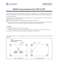
(3) The model name "OPC-E1-RS" is printed on the RS-485 communications
card. (See Figure 1.)
If you suspect the product is not working properly or if you have any questions
about your product, contact the shop where you bought the product or your local
Fuji branch office.
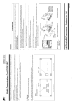
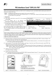
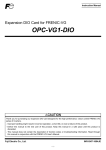
Hooks
Model
name
SW9
SW10
Figure 1
Figure 2
2. Installation
When handling the RS-485 communications card and interface PCB, take any
antistatic measure or hold their hooks taking care not to directly touch their circuit boards; otherwise, the static electricity charged in your body may damage
them.
(1) If more than one inverter is connected in your system and you will install
the RS-485 communications card to the terminal inverter, then be sure to
turn SW9 (shown in Figure 1) on the card to the ON position.
(2) If the terminal cover is installed, insert your finger into the opening (next to
"PULL") provided in the bottom of the terminal cover and pull the cover
towards you.
For details on how to remove the terminal cover, refer to the
Hooks
Interface PCB
Figure 3
FRENIC-Multi Instruction Manual (INR-SI47-1204-E), Chapter 2, Section
2.3 "Wiring."
(3) If the interface printed circuit board (interface PCB) is installed, push the
hooks provided on both ends of the PCB and pull it up with both hands as
shown in Figure 3. (Store the removed interface PCB for future use.)
(4) Connect the CN3 connector (shown in Figure 2) on the RS-485 communications card to the connector on the inverter until it clips into place.
(5) For inverters of less than 7.5 HP: Before reinstalling the terminal cover, cut
off the two barriers (see Figure 4) of the RS-485 communications cable
outlets on the main circuit terminal block cover.
(6) Fit the latches provided on the upper end of the terminal cover into the
openings in the inverter, then close the terminal cover, taking care not to
pinch control signal lines.
When reinstalling the terminal cover, refer to the FRENIC-Multi Instruction Manual (INR-SI47-1204-E), Chapter 2, Section 2.3 "Wiring."
CN3
RS-485 communications
card
Main circuit terminal
block cover
Barriers of the RS-485
communications cable
outlets
Figure 4
• For inverters of less than 7.5 HP: When performing the wiring for the
main circuit terminals, remove the RS-485 communications card beforehand.
• When replacing the conventional FVR-E11S series with the FRENIC-Multi series, be sure to turn signal switch SW10 to the
"2" position (in Figure 1). The pin assignment of this RS-485 communications card is different from that of the FVR-E11S's
RJ-45 connector used for RS-485 communication. For details, refer to the RS-485 Communication User's Manual
(MEH448b).
• If a communications error occurs due to a communications cable too long and the transmission speed too high, wind 3 turns
of a communications cable through a noise reduction core (e.g., MA055 38.1/19/12.7A manufactured by JFE Ferrite Corporation).
Fuji Electric Systems Co., Ltd.
Fuji Electric Corp. of America
http://www.fujielectric.com/fecoa/
47520 Westinghouse Drive Fremont, CA 94539, U.S.A.
Tel.+1-510-440-1060 Fax.+1-510-440-1063
Toll-free support 1-888-900-FUJI(3854)
IN
R-SI47-1089-EU REV. 052010
Information subject to change without notice.
