1
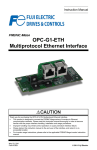
Instruction Manual Digital Interface Option "OPC-E1-DIO" Thank you for purchasing our digital interface option. • Read through this instruction manual and be familiar with the digital interface option before proceeding with installation, connections (wiring), operation, or maintenance and inspection. • Improper handling might result in incorrect operation, a short life, or even a failure of this product as well as the motor. • Deliver this manual to the end user of this product. Keep this manual in a safe place until this product is discarded. Fuji Electric Systems Co., Ltd. INR-SI47-1285-EU REV 052010 Copyright © 2008 Fuji Electric FA Components & Systems Co., Ltd. All rights reserved. No part of this publication may be reproduced or copied without prior written permission from Fuji Electric FA Components & Systems Co., Ltd. All products and company names mentioned in this manual are trademarks or registered trademarks of their respective holders. The information contained herein is subject to change without prior notice for improvement. Preface Thank you for purchasing our digital interface option. Mounting the digital interface option on your FRENIC-Multi makes it possible to specify frequency commands with binary code (8 or 12 bits) or BCD (4-bit Binary Coded Decimal) code. It also enables monitoring with 8-bit binary code. This instruction manual does not contain inverter handling instructions. Read through this instruction manual in conjunction with the FRENIC-Multi Instruction Manual and be familiar with proper handling and operation of this product. Improper handling might result in incorrect operation, a short life, or even a failure of this product. Keep this manual in a safe place. Safety precautions Read this manual thoroughly before proceeding with installation, connections (wiring), operation, or maintenance and inspection. Ensure you have sound knowledge of the device and familiarize yourself with all safety information and precautions before proceeding to operate the inverter. Safety precautions are classified into the following two categories in this manual. Failure to heed the information indicated by this symbol may lead to dangerous conditions, possibly resulting in death or serious bodily injuries. Failure to heed the information indicated by this symbol may lead to dangerous conditions, possibly resulting in minor or light bodily injuries and/or substantial property damage. Failure to heed the information contained under the CAUTION title can also result in serious consequences. These safety precautions are of utmost importance and must be observed at all times. i Installation and wiring • Before starting installation and wiring, turn the inverter's power OFF and wait at least five minutes. Further, check with a multimeter or the similar instrument that the DC link bus voltage between the P (+) and N (-) terminals is lower than 25 VDC. • Qualified electricians should carry out wiring. Otherwise, an electric shock could occur. • Do not use the product that is damaged or lacking parts. Doing so could cause a fire, an accident, or injuries. • Prevent lint, paper fibers, sawdust, dust, metallic chips, or other foreign materials from getting into the inverter and the option. Otherwise, a fire or an accident might result. • Incorrect handling in installation/removal jobs could cause a failure. A failure might result. • Noise may be emitted from the inverter, motor and wires. Implement appropriate measure to prevent the nearby sensors and devices from malfunctioning due to such noise. Otherwise, an accident could occur. Operation • Be sure to install the terminal cover and option terminal cover before turning the inverter's power ON. Do not remove the cover when the inverter power is ON. Otherwise, an electric shock could occur. • Do not operate switches with wet hands. Doing so could cause an electric shock. • If you set the function codes wrongly or without completely understanding the FRENIC-Multi Instruction Manual and the FRENIC-Multi User's Manual, the motor may rotate with a torque or at a speed not permitted for the machine. Confirm and adjust the setting of the function codes before running the inverter. Otherwise, an accident could occur. ii Maintenance and inspection, and parts replacement • Before proceeding to the maintenance/inspection jobs, turn the inverter's power OFF and wait at least five minutes. Further, check with a multimeter or the similar instrument that the DC link bus voltage between the P (+) and N (-) terminals is lower than 25 VDC. Otherwise, an electric shock could occur. • Maintenance, inspection, and parts replacement should be made only by qualified persons. • Take off the watch, rings and other metallic objects before starting work. • Use insulated tools. Otherwise, an electric shock or injuries could occur. Disposal • Treat the interface card(s) as an industrial waste when disposing of it. Otherwise injuries could occur. Others • Never modify the interface option(s). Doing so could cause an electric shock or injuries. iii Icons The following icons are used throughout this manual. This icon indicates information which, if not heeded, can result in the product not operating to full efficiency, as well as information concerning incorrect operations and settings which can result in accidents. This icon indicates information that can prove handy when performing certain settings or operations. This icon indicates a reference to more detailed information. Table of Contents Preface ............................................. i Safety precautions.................................. i Chapter 1 BEFORE USING THE INVERTER........................................1-1 1.1 Acceptance Inspection .............1-1 1.2 Applicable Inverters .................1-1 1.3 Installation of the Interface Option1-2 1.4 Wiring for the Interface Option .1-6 1.5 Terminal Allocation of Interface Option PCB..........................................1-7 Chapter 2 WIRING............................2-1 2.1 Connection Diagram ................2-1 2.2 Terminal Functions ...................2-2 2.3 Electrical Specifications ...........2-2 2.4 Input Interface ..........................2-3 2.4.1 Switching between SINK and SOURCE for digital input terminals ([I1] to [I12] and [SEL]) .......2-3 2.4.2 Connection diagrams for SINK/SOURCE input modes..........................................2-3 2.4.3 Precaution on the use of a contact relay....................................2-4 2.5 Output Interface .......................2-4 Chapter 3 CONFIGURING INVERTER'S FUNCTION CODE ...........3-1 Chapter 4 DETAILS OF FUNCTION CODES .......................................4-1 Chapter 5 I/O CHECKING ................5-1 Chapter 6 PROTECTIVE FUNCTION6-1 iv Chapter 1 BEFORE USING THE INVERTER 1.1 Acceptance Inspection Unpack the package and check the following: (1) A digital interface option and the following accessories are contained in the package. (See Figure 1.1.) - Two option connection cables (A short one for inverters with a capacity of 5 HP or below and a long one for inverters with a capacity of 7.5 HP or above) - One option fixing screw - Digital Interface Option Instruction Manual (this manual) (2) The interface option and accessories have not been damaged during transportation—there should be no dents or parts missing. (3) The model name "OPC-E1-DIO" is printed on the nameplate attached to the right side of the interface option. (See Figure 1.1.) If you suspect the product is not working properly or if you have any questions about your product, contact your Fuji Electric representative. Figure 1.1 Digital Interface Option and Accessories 1-1 1.2 Installation of the Interface Option Turn the inverter's power OFF and wait for at least five minutes. Further, check that the DC link bus voltage between the P (+) and N (-) terminals is lower than 25 VDC. Otherwise, electric shock could occur. • Do not use the product that is damaged or lacking parts. Doing so could cause a fire, accident, or injury. • Prevent lint, paper fibers, sawdust, dust, metallic chips, or other foreign materials from getting into the inverter and the interface option. Otherwise, a fire or an accident might result. • Incorrect handling in installation/removal jobs could cause a failure. A failure might result. When handling the interface option, take any antistatic measure or hold the plastic parts taking care not to directly touch the circuit board; otherwise, the static electricity charged in your body may damage it. 1-2 Before mounting the interface option, perform the wiring for the main circuit terminals and control circuit terminals on the inverter. (1) Remove the terminal cover from the inverter. Note: For inverters with a capacity of 7.5 to 20 HP, you need to remove the terminal cover fixing screw to remove the terminal cover. For details on how to remove the terminal cover, refer to the FRENIC-Multi Instruction Manual (INR-SI47-1204-E), Chapter 2, Section 2.3 "Wiring." (2) Connect the option connection cable to the CN1 connector on the interface printed circuit board (interface PCB) on the inverter. Use the short cable for inverters with a capacity of 5 HP or below, and the long cable for the ones with a capacity of 7.5 HP or above. (3) Mount the terminal cover. For details on how to mount the terminal cover, refer to the FRENIC-Multi Instruction Manual, Chapter 2, Section 2.3 "Wiring." (4) Push the hooks provided on both sides of the keypad and pull the keypad up and out of the inverter. For details on how to remove the keypad, refer to the FRENIC-Multi Instruction Manual, Chapter 2, Section 2.4 "Mounting and Connecting a Keypad." Terminal cover fixing screw (for inverters with a capacity of 7.5 to 20 HP) Figure 1.2 Connecting the Option Connection Cable to the Interface PCB and Removing the Keypad (For inverters with a capacity of 15 and 20 HP) 1-3 (5) Mount the interface option on the inverter, making the RJ-45 connector on the back side of the option engage with the RJ-45 connector on the inverter (to which the keypad had been connected). (6) Connect the keypad to the RJ-45 connector on the front side of the interface option, then secure the keypad and interface option to the inverter with the option fixing screw (that comes with the interface option). When using the keypad at a remote site, secure the interface option without the keypad to the inverter with the screw. Tightening torque: 0.6 N·m(0.4 lbf·ft) Take care not to tighten the option fixing screw too much. Doing so could make the screw defective. Figure 1.3 Mounting the Digital Interface Option and the Keypad 1-4 (7) Slightly pull the bottom of the option terminal cover towards you and remove it downward. (8) Connect the other end of the option connection cable (whose end has been connected to the interface PCB on the inverter in step (2) above) to the CN1 connector on the interface option printed circuit board (interface option PCB). (9) Mount the option terminal cover. First fit the bosses on the top of the cover into the square holes provided in the interface option, and then push the bottom of the cover until it snaps into place. Figure 1.4 Connecting the Option Connection Cable to the Interface Option PCB 1-5 1.3 Wiring for the Interface Option • Before starting installation, turn off the power to the inverter and wait for at least five minutes. Further, check the DC link circuit voltage between the P (+) and N (-) terminals to be lower than 25 VDC. • Qualified electricians should carry out wiring. Otherwise, electric shock could occur. The inverter, motor, and wiring emit electrical noise. Take appropriate measures to prevent the nearby sensors and devices from malfunctioning due to such noise. Otherwise, an accident could occur. Perform wiring for the interface card observing the precautions below. Refer to the connection diagrams shown in Figure 2.1 in Chapter 2. (1) Turn the inverter's power OFF. (2) Use shielded wires. (3) To prevent malfunction due to noise, keep the wiring for the interface option PCB away from the main circuit wiring and other power lines as far as possible (at least 10 cm). Never install them in the same wire duct. (4) Complete wiring before turning the inverter ON. 2 2 (5) The wire size applicable to the terminals on the interface option is AWG24 to AWG18(0.20 mm to 0.82 mm ) When using stripped wires (without attaching a crimp terminal), strip the wire end by 5 to 7 mm(0.2 to 0.28 in) (Figure 1.5) When using a crimp terminal, attach a vinyl-insulated ferrule. Loosen the terminal screw, insert the wire end into above the metal part of the terminal block, and tighten the screw to fasten it. (Figure 1.6) Approx. 6.0 mm(0.24 in) Figure 1.5 Wire End Treatment (For Connection to Terminals on Interface Option) Figure 1.6 Connecting to a Terminal on Interface Option Recommended wire: AWG24 to AWG18(0.20 mm to 0.82 mm ), with rated temperature 105C(221 F) (UL) 2 2 1-6 1.4 Terminal Allocation on the Interface Option PCB M1 SEL I11 CM I12 I9 I10 I7 I8 I5 I6 I3 I4 I1 I2 O8 CM M2 O7 O6 O4 O5 * Screw size: M2 * Tightening torque: 0.22 to 0.25 N・m(0.16 to 0.18 lbf・ft) Figure 1.7 Terminal Allocation on the Interface Option PCB 1-7 O2 O3 O1 Chapter 2 WIRING 2.1 Connection Diagram PLC CM M1 CM 24 VDC Figure 2.1 Connection Diagram 2-1 2.2 Terminal Functions Table 2.1 lists terminal symbols, names and functions of the terminals on the digital interface option. Table 2.1 Terminals and Their Specifications Terminal symbol Name Functions [I1] to [I12] Input terminals For entry of frequency commands [SEL] Input terminal For entry of Hold signal [M1] External power supply for input terminal For external power supply for frequency command input [CM] Common terminal for input Common terminal command input Output terminals For monitoring Common terminal for output For monitoring [O1] to [O8] [M2] for frequency 2.3 Electrical Specifications Table 2.2 lists the electrical specifications for the digital interface option. Table 2.2 Electrical Specifications Termin al symbo l [O1] to [O8] SOURCE mode SINK mode SOURCE mode SINK mode Input voltage at ON [I1] to [I12], SEL Specifications Symb ol Item Typical Max. 0V - 2V - 3.2 mA - Vcc = 27 V VIL = 0 V - - 4.5 mA VIH 22 V 24 V 27 V Leakage current at OFF IIH - - 0.5 mA Input voltage at ON VIL 22 V 24 V 27 V Input voltage at OFF VIH 0V 1V 5V Vcc = 24 V VIL = 0 V - 3.2 mA - Vcc = 27 V VIL = 0 V - - 4.5 mA Vo = 27 V - - 50 mA current Output OFF voltage at at Input current at ON IIL IIL Vcc = 22 V Min. Vcc = 24 V VIL = 0 V Output ON VIL Conditions SINK current at ON IOL Output ON voltage at VOL IOL = 50 mA - 2V 3V Output OFF voltage at VOH - 24 VDC 27 VDC Leakage current at IOH OFF Vo = 24 V - - 0.5 mA SOURCE current at IOL ON Vo = 27 V - - -50 mA VOL IOL = -50 mA - 2V 3V VOH - 24 VDC 27 VDC - - -0.5 mA Output ON voltage at Output OFF voltage at Leakage current at IOH OFF Vo = 24 V 2-2 Input Interface 2.3.1 Switching between SINK and SOURCE for digital input terminals ([I1] to [I12] and [SEL]) The input mode is switchable between SINK and SOURCE for digital input terminals ([I1] to [I12] and [SEL]) by using the slide switch SW11 on the interface option PCB (Figure 1.7 in Chapter 1). Specify the input mode referring to Table 2.3 below. Table 2.3 Configuration of Slide Switch SW11 Input mode SINK default) (factory Slide switch position SINK side SINK SOURCE SINK SOURCE SOURCE side SOURCE 2.3.2 Connection diagrams for SINK/SOURCE input modes Table 2.4 shows connection diagrams for input interface circuits. Table 2.4 Connections of Input Interface Circuits Connection diagram Power supply SINK mode SOURCE mode F R E N IC -M u lti [P LC ] [PLC] 2 4 to 2 7 V D C Internal [M 1] S IN K [I1] to [I1 2], [S E L] D igital in te rfa ce o ption [M 1] SINK [I1] to [I12], [SEL] SOURCE CM CM [CM] [C M ] C om m on Com m on [C M ] [M 1] S IN K 24 V [I1] to [I12], [S E L] [C M ] D ig ital in terfac e o ption D igital interface option SOURCE [CM] [C M ] External FRENIC-M ulti 24 to 27 VDC [M1] SINK SOURCE 24 V [I1] to [I12], [SEL] [CM] CM 2-3 Digital interface option SOURCE CM 2.3.3 Precaution on the use of a contact relay To configure input circuits using contact relays, use highly reliable relays. 2.4 Output Interface Table 2.5 shows connection diagrams for output interface circuits. Table 2.5 Connections of Output Interface Circuits Connection diagram Digital interface option [M2] SINK mode [O1] to [O8] 24 V Digital interface option [M2] SOURCE mode [O1] to [O8] 24 V The output interface circuit should be configured with an external power supply. In the SINK mode, the positive (+) side of the external power supply should be connected to terminal [M2] on the interface option, and in the SOURCE mode, the negative (-) side. 2-4 Chapter 3 CONFIGURING INVERTER'S FUNCTION CODE Tables 3.1 and 3.2 list the function code and its parameters. Table 3.1 Definition of Frequency Command Sources (Input) Function Name Data Description Remarks code F01 Frequency Frequency command sourced from the digital 11 (C30) Command 1 interface option (Frequency Other Command 2) than 11 Frequency command specified by function codes o20 Select input 0 8-bit, binary frequency command mode 1 12-bit, binary frequency command (Note) 4 3-digit, BCD frequency command (0 to 99.9 Hz) 5 3-digit, BCD frequency command (0 to 999 Hz) BCD: Binary Coded Decimal Note: Terminal [SEL] comes to be exclusive to Hold signals. When SEL = 0, the interface option receives input data (I1 to I12). Table 3.2 Monitor Items Selectable (Output) Function Name Data Monitoring item Remarks code o21 Output frequency (before slip 100%/8-bit (Note Select 0 compensation) 1) output Output frequency (after slip 100%/8-bit (Note mode 1 compensation) 1) 200%/8-bit (Note Output current 2 2) 100%/8-bit (Note Output voltage 3 3) 200%/8-bit (Note Output torque 4 4) 200%/8-bit (Note Load factor 5 5) 200%/8-bit (Note Input power 6 6) 100%/8-bit (Note PID feedback amount 7 7) 100%/8-bit (Note DC link bus voltage 9 8) 200%/8-bit (Note Motor output 13 9) 100%/8-bit (Note PID command (SV) 15 10) 100%/8-bit (Note PID output (MV) 16 11) Individual signal output (Note 12) 99 (Note 1) Output frequency monitor = (Output frequency / Maximum frequency) 255 (Note 2) Output current monitor = (Output current / (Inverter's rated output current 2)) 255 (Note 3) Output voltage monitor = (Output voltage / 250 V) 255: For 200 V class series = (Output voltage / 500 V) 255: For 400 V class series (Note 4) Output torque monitor = (Output torque / (Motor rated torque 2) 255 (Note 5) Load factor monitor = (Load factor / (Motor rated load 2)) 255 (Note 6) Input power monitor = (Input power / (Inverter's rated output 2)) 255 (Note 7) PID feedback amount monitor = (PID feedback amount / Feedback amount 100%) 255 (Note 8) DC link bus voltage monitor = (DC link bus voltage / 500 V) 255: For 200 V class series = (DC link bus voltage / 1000 V) 255: For 400 V class series (Note 9) Motor output monitor = (Motor output / (Motor rated output 2)) 255 (Note 10)PID command (SV) monitor = (PID command / Feedback amount 100%) 255 (Note 11)PID output (MV) monitor = (PID output / Maximum frequency) 255 (Note 12)Terminal output signals RUN, FDT, FAR, LU, OL, IPF (assigned to the general-purpose programmable output terminals) are issued individually as bit information. For details of bit information (output bit position), refer to Table 4.2 in Chapter 4 "DETAILS OF FUNCTION CODES." If the monitored value exceeds 100%, "11111111 (255)" is output. 3-1 Chapter 4 DETAILS OF FUNCTION CODES Tables 4.1 and 4.2 show the configuration of function codes o19 and o20 and the details of the terminal functions. Table 4.1 Definition of Frequency Command Sources (Input) Functi on code Data o20 0 Input signal name 8-bit binary frequency command Terminal function and configuration details LSB MSB SEL I12 I11 I10 I9 I8 I7 Invalid I6 I5 I4 I3 I2 I1 Frequency command Hold signal When SEL = 0, data update is available. When SEL = 1, data update is not available. (1)Setting resolution = Specified maximum frequency (1/255) (2)Upper/lower limiters are given priority.. 1 12-bit binary frequency command LSB MSB SEL I12 I11 I10 I9 I8 I7 I6 I5 I4 I3 I2 I1 Frequency command Hold signal When SEL = 0, data update is available. When SEL = 1, data update is not available. (1)Setting resolution = Specified maximum frequency (1/4095) (2)Upper/lower limiters are given priority.. 4 3-digit BCD frequency command (0 to 99.9 Hz) LSB MSB SEL I12 I11 I10 I9 I8 Tens place of Hz I7 I6 I5 I4 Units place of Hz I3 I2 I1 Tenth place of Hz Hold signal When SEL = 0, data update is available. When SEL = 1, data update is not available. (1)Frequency can be specified within the range of 0 to 99.9 Hz (Setting resolution = 0.1 Hz). (2)Upper/lower limiters are given priority.. (3)If a frequency command exceeding the maximum frequency is input, the maximum frequency is output. 5 3-digit BCD frequency command (0 to 999 Hz) MSB SEL I12 I11 I10 I9 Hundreds place of Hz Hold signal LSB I8 I7 I6 Tens place of Hz I5 I4 I3 I2 I1 Units place of Hz When SEL = 0, data update is available. When SEL = 1, data update is not available. (1)Frequency can be specified within the range of 0 to 999 Hz (Setting resolution = 1 Hz). (2)Upper/lower limiters are given priority.. (3)If a frequency command exceeding the maximum frequency is input, the maximum frequency is output. 4-1 Table 4.2 Monitor Items Selectable (Output) Functi on code Data o21 0 1 2 Output signal name Output frequency (before slip compensatio n) Output frequency (after slip compensatio n) Terminal function and configuration details MSB LSB O8 O7 O6 O5 O4 O3 O2 O1 100% of maximum frequency /8 bits MSB LSB O8 O7 O6 O5 O4 O3 O2 O1 100% of maximum frequency /8 bits Output current MSB LSB O8 O7 O6 O5 O4 O3 O2 O1 200% of inverter's rated output current / 8 bits 3 Output voltage MSB LSB O8 O7 O6 O5 O4 O3 O2 O1 100% of 250 V / 8 bits: 200 V class series 100% of 500 V / 8 bits: 400 V class series 4 Output torque MSB LSB O8 O7 O6 O5 O4 O3 O2 O1 200% of motor rated torque / 8 bits 5 Load factor MSB LSB O8 O7 O6 O5 O4 O3 O2 O1 200% of motor rated load / 8 bits 6 Input power MSB LSB O8 O7 O6 O5 O4 O3 O2 O1 200% of inverter's rated output / 8 bits 7 PID feedback amount MSB LSB O8 O7 O6 O5 O4 O3 O2 O1 100% of feedback amount / 8 bits 4-2 Table 4.2 Monitor Items Selectable (Output) (Continued) Functio n code Data o21 9 Output signal name Terminal function and configuration details DC link bus voltage MSB LSB O8 O7 O6 O5 O4 O3 O2 O1 100% of 500 V / 8 bits: 200 V class series 100% of 1000 V / 8 bits: 400 V class series 13 Motor output MSB LSB O8 O7 O6 O5 O4 O3 O2 O1 200% of motor rated output / 8 bits 15 PID command (SV) MSB LSB O8 O7 O6 O5 O4 O3 O2 O1 100% of feedback amount / 8 bits 16 PID output (MV) MSB LSB O8 O7 O6 O5 O4 O3 O2 O1 100% of maximum frequency / 8 bits 99 Individual signal output MSB LSB O8 O7 O6 O5 O4 O3 O2 O1 RUN : Inverter running Fixed at "0" FDT : Frequency detected FAR : Frequency arrival signal LU : Undervoltage detected (Inverter stopped) IOL : Inverter output limiting IPF : Auto-restarting after momentary power failure Individual output signals are functionally equivalent to the general-purpose output terminals on the inverter. 4-3 Chapter 5 I/O CHECKING Using Menu #4 "I/O Checking" in Program mode of the FRENIC-Multi displays the I/O status of external signals on the LED monitor of the keypad. For details of Menu #4 "I/O Checking," refer to the FRENIC-Multi Instruction Manual (INR-SI47-1204-E), Chapter 3, Section 3.4 "Programming Mode." The I/O status of the digital interface option can be displayed with ON/OFF of the LED segment or in hexadecimal. Signals are assigned to the LED segments as shown below. Table 5.1 Display with ON/OFF of LED Segments Segment a b c d e f g dp LED4 — — — — — — — — LED3 O1 O2 O3 O4 O5 O6 O7 O8 LED2 I9 I10 I11 I12 SEL — — — LED1 I1 I2 I3 I4 I5 I6 I7 I8 Table 4.2 Segment Display for I/O Signal Status in Hexadecimal LED number LED4 Bit 15 14 13 Input terminal - - - Output terminal - - - LED3 12 LED2 LED1 11 10 9 8 7 6 5 4 3 2 1 0 SEL I12 I11 I10 I9 I8 I7 I6 I5 I4 I3 I2 I1 - - - O8 O7 O6 O5 O4 O3 O2 O1 - - 5-1 Chapter 6 PROTECTIVE FUNCTION Option communications error (er4 ) Problem A communications error has occurred between the digital interface option and the inverter. What to Check and Suggested Measures Possible Causes (1) There is a problem with the connection between the interface option and the inverter. Check whether the connector on the interface option is firmly engaged with that of the inverter. (2) Strong electrical noise. Check whether appropriate noise control measures have been implemented (e.g. correct grounding and routing of signal wires, communications cables, and main circuit wires). Reload the option card into the inverter. Implement noise control measures. When no o code is displayed even if a digital interface option is mounted, check whether the connector on the interface option is firmly engaged with that of the inverter. In this case, er4 does not appear. 6-1 Digital Interface Option "OPC-E1-DIO" Instruction manual First Edition, February 2008 Fuji Electric FA Components & Systems Co., Ltd. The purpose of this instruction manual is to provide accurate information in handling, setting up and operating of the digital interface option. Please feel free to send your comments regarding any errors or omissions you may have found, or any suggestions you may have for generally improving the manual. In no event will Fuji Electric FA Components & Systems Co., Ltd. be liable for any direct or indirect damages resulting from the application of the information in this manual. MEMO Fuji Electric Systems Co., Ltd. Fuji Electric Corp. of America 47520 Westinghouse Drive Fremont, CA 94539, U.S.A. Tel.+1-510-440-1060 Fax.+1-510-440-1063 Toll-free support 1-888-900-FUJI(3854) INR-SI47-1285-EU Rev 052010 http://www.fujielectric.com/fecoa/ Information subject to change without notice.