1
I-SV-600B
Installation, Setup
and Operation
INSTRUCTIONS
for
SUNNEN®
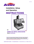
VERTICAL HONING MACHINE
(FOR AUTOMOTIVE & INDUSTRIAL APPLICATIONS)
Model SV-10
READ THE FOLLOWING INSTRUCTIONS THOROUGHLY AND CAREFULLY BEFORE UNPACKING,
INSPECTING, OR INSTALLING THE SUNNEN® AUTOMATIC VERTICAL HONING MACHINE.
“SUNNEN AND THE SUNNEN LOGO ARE REGISTERED TRADEMARKS OF SUNNEN PRODUCTS COMPANY.”
SUNNEN ® PRODUCTS COMPANY • 7910 MANCHESTER AVENUE • ST. LOUIS, MO 63143, U.S.A. • PHONE: 314-781-2100
GENERAL INFORMATION
The Sunnen® equipment has been designed and engineered for a wide variety of parts within the capacity and limitation of the equipment. With proper care
and maintenance this equipment will give years of service.
READ THE FOLLOWING INSTRUCTIONS CAREFULLY AND THOROUGHLY BEFORE UNPACKING, INSPECTING, OR INSTALLING THIS EQUIPMENT.
IMPORTANT: Read any supplemental instructions BEFORE installing this equipment. These supplemental instructions give you important information to
assist you with the planning and installation of your Sunnen equipment.
Sunnen Technical Service Department is available to provide telephone assistance for installation, programming, & troubleshooting of your Sunnen
equipment. All support is available during normal business hours, 8:00 AM to 4:30 PM Central Time.
Review all literature provided with your Sunnen equipment. This literature provides valuable information for proper installation, operation, and maintenance
of your equipment. Troubleshooting information can also be found within the Instructions. If you cannot find what you need, call for technical support.
Where applicable, programming information for your Sunnen equipment is also included. Most answers can be found in the literature packaged with your
equipment.
Help us help you. When ordering parts, requesting information, or technical assistance about your equipment, please have the following
information available:
• Have ALL MANUALS on hand. The Customer Services Representative or Technician will refer to it.
• Have Model Number and Serial Number printed on your equipment Specification Nameplate.
• Where Applicable: Have Drive model and all nameplate data. Motor type, brand, and all nameplate data.
For Troubleshooting, additional information may be required:
• Power distribution information (type - delta, wye, power factor correction; other major switching devices used, voltage fluctuations)
• Installation Wiring (separation of power & control wire; wire type/class used, distance between drive and motor, grounding).
• Use of any optional devices/equipment between the Drive & motor (output chokes, etc.).
For fast service on your orders call:
Sunnen Automotive Customer Service toll free at: 1-800-772-2878
Sunnen Industrial Customer Service toll free at: 1-800-325-3670
Customers outside the USA, contact your local authorized Sunnen Distributor.
Additional information available at: http://www.sunnen.com or e-mail: [email protected]
NOTE: Sunnen reserves the right to change or revise specifications and product design in connection with any feature of our products contained herein.
Such changes do not entitle the buyer to corresponding changes, improvements, additions, or replacements for equipment, supplies or accessories
previously sold. Information contained herein is considered to be accurate based on available information at the time of printing. Should any discrepancy of
information arise, Sunnen recommends that user verify the discrepancy with Sunnen before proceeding.
ESD PREVENTION REVIEW
Let's review the basics of a sound static control system and its effective implementation. First, in the three step plan:
1.
Always ground yourself when handling sensitive components or assemblies.
2.
Always use a conductive or shielded container during storage or transportation. These materials create a Faraday
cage which will isolate the contents from static charges.
3.
Open ESD safe containers only at a static safe work station.
At the static safe work station, follow these procedures before beginning any work:
A.
Put on your wrist strap or foot grounding devices.
B.
Check all grounding cords to make sure they are properly connected to ground, ensuring the effective dissipation of static charges.
C.
Make sure that your work surface is clean and clear of unnecessary materials, particularly common plastics.
D.
Anti-static bubble wrap has been included for use at the machine when an ESD safe workstation is not available.
You are now properly grounded and ready to begin work. Following these few simple rules and using a little common sense will go a long
way toward helping you and your company in the battle against the hazards of static electricity. When you are working with ESD sensitive devices, make sure you:
GROUND
ISOLATE
NEUTRALIZE
ii
SUNNEN® LIMITED PRODUCT WARRANTY
Sunnen® Products Company and its subsidiaries (SPC) warrant that all new SPC honing machines, gaging equipment, tooling, and related equipment will
be free of defects in material and/or workmanship for a period of one year from the date of original shipment from SPC.
Upon prompt notification of a defect during the one-year period, SPC will repair, replace, or refund the purchase price, with respect to parts that prove to be
defective (as defined above). Any equipment or tooling which is found to be defective from improper use will be returned at the customer's cost or repaired
(if possible) at customer's request. Customer shall be charged current rates for all such repair.
Prior to returning any SPC product, an authorization (RMA#) and shipping instructions must be obtained from the Customer Service Department or items
sent to SPC will be returned to the customer.
Warranty Limitations and Exclusions This Warranty does not apply to the following:
• Normal maintenance items subject to wear and tear: (belts, fuses, filters, etc).
• Damages resulting from but not limited to:
› Shipment to the customer (for items delivered to customer or customer's agent F.O.B., Shipping Point)
› Incorrect installation including improper lifting, dropping and/or placement
› Incorrect electric power (beyond +/- 10% of rated voltage) including intermittent or random voltage spikes or drops
› Incorrect air supply volume and/or pressure and/or contaminated air supply
› Electromagnetic or radio frequency interference from surrounding equipment (EMI, RFI)
› Storm, lightning, flood or fire damage
› Failure to perform regular maintenance as outlined in SPC manuals
› Improper machine setup or operation causing a crash to occur
› Misapplication of the equipment
› Use of non-SPC machines, tooling, abrasive, fixturing, coolant, repair parts, or filtration
› Incorrect software installation and/or misuse
› Non-authorized customer installed electronics and/or software
› Customer modifications to SPC software
THE LIMITED WARRANTY DESCRIBED HEREIN IS EXPRESSLY IN LIEU OF ALL ANY OTHER WARRANTIES. SPC MAKES NO REPRESENTATION OR WARRANTY OF ANY
OTHER KIND, EXPRESS OR IMPLIED, WHETHER AS TO MERCHANTABILITY, FITNESS FOR A PARTICULAR PURPOSE OR ANY OTHER MATTER. SPC IS NOT
RESPONSIBLE FOR THE IMPROPER USE OF ANY OF ITS PRODUCTS. SPC SHALL NOT BE LIABLE FOR DIRECT, INDIRECT, INCIDENTAL, OR CONSEQUENTIAL
DAMAGES INCLUDING BUT NOT LIMITED TO: LOSS OF USE, REVENUE, OR PROFIT. SPC ASSUMES NO LIABILITY FOR PURCHASED ITEMS PRODUCED BY OTHER
MANUFACTURERS WHO EXTEND SEPARATE WARRANTIES. REGARDLESS OF ANY RIGHTS AFFORDED BY LAW TO BUYER, SPC's LIABILITY, IF ANY, FOR ANY AND
ALL CLAIMS FOR LOSS OR DAMAGES WITH RESPECT TO THE PRODUCTS, AND BUYER'S SOLE AND EXCLUSIVE REMEDY THEREFORE, SHALL IN ALL EVENTS BE
LIMITED IN AMOUNT TO THE PURCHASE PRICE OF THAT PORTION OF THE PRODUCTS WITH RESPECT TO WHICH A VALID CLAIM IS MADE.
Shipping Damages
Except in the case of F.O.B., Buyer's destination shipments, SPC will not be liable for any settlement claims for obvious and/or concealed shipping damages.
The customer bears the responsibility to unpack all shipments immediately and inspect for damage. When obvious and/or concealed damage is found, the
customer must immediately notify the carrier's agent to make an inspection and file a claim. The customer should retain the shipping container and packing
material.
SUNNEN® SOFTWARE LICENSE AGREEMENT
This document is a Legal Agreement between you, as user and licensee (Licensee), and Sunnen® Products Company (SPC) with respect to preprogrammed
software (Software) provided by SPC for use on SPC Equipment. By using the Software, you, as Licensee, agree to become bound by the terms of this
Agreement.
In consideration of payment of the license fee (License Fee) which is part of the price evidenced by your receipt (Receipt), SPC grants to you as Licensee
a non-exclusive right, without right to sub-license, to use the particular copy of the SPC Software licensed hereunder only on the particular equipment sold with
the Software. SPC reserves all rights including rights not otherwise expressly granted, and retain title and ownership to the Software including all subsequent copies or updates in any media. The Software and all accompanying written materials are covered by copyrights owned by SPC. If supplied on
removable media (floppy disk), you, as Licensee, may copy the Software only for back up purposes; or you may request that SPC copy the Software for you
for the same purposes. All other copying of the Software or of the accompanying written materials is expressly forbidden and is in violation of the Agreement.
The Software and accompanying written materials (including the user's manual, if any) are provided in an "as is" condition without warranty of any kind
including the implied warranties of merchantability and fitness for a particular purpose, even if SPC has been advised of this purpose. SPC specifically does
not warrant that it will be liable as a result of the operation of the Software for any direct, indirect, consequential or accidental damages arising out of the
use of or inability to use such product even if SPC has been advised of the possibility of such use. It is recognized that some states do not allow the exclusion or limitation of liability for consequential or accidental damages and to the extent this is true, the above limitations may not apply.
Any alteration or reverse engineering of the software is expressly forbidden and is in violation of this agreement.
SPC reserves the right to update the software covered by this agreement at any time without prior notice and any such updates are covered by this
agreement.
iii
SAFETY INSTRUCTIONS
READ FIRST
This machine, like any equipment, may be dangerous if used improperly. Please
read all warnings and instructions before attempting to use this machine.
Always disconnect power at main enclosure before servicing machine.1
Always wear eye protection when operating this machine.
NEVER open or remove any machine cover or protective guard with power "ON."
Always disconnect power at main enclosure before servicing this equipment.1
DO NOT attempt any repair or maintenance procedure beyond those described in
this book. Contact your Sunnen® Field Service Engineer or Technical Services
Representative for repairs not covered in these instructions.
Due to the wide variety of machine configurations, all possibilities cannot be
described in these instructions. Instructions for safe use and maintenance of
optional equipment ordered through Sunnen, will be provided through separate
documentation and/or training provided by your Sunnen Field Service Engineer or
Technical Services Representative.
DO NOT attempt to defeat any safety device on this machine or on any of the
optional equipment.
If specially built automation components are added to this system, be sure that
safety is not compromised. If necessary, obtain special enlarged work area safety
system from Sunnen Products Co.
Indicates CE version ONLY.
1
DO NOT touch electrical components until main input power has been turned off and CHARGE
lamps are extinguished. WARNING: The capacitors are still charged and can be quite dangerous.
iv
TABLE OF CONTENTS
Page
TABLE OF CONTENTS . . . . . . . . . . . . . . . . . . . . . . . . . . . . . . . . . . . . . . . . . . . . . . . . . . . . . . . . . . . . . . . . v
GENERAL INFORMATION & SPECIFICATIONS . . . . . . . . . . . . . . . . . . . . . . . . . . . . . . . . . . . . . . . . . vi
INTRODUCTION . . . . . . . . . . . . . . . . . . . . . . . . . . . . . . . . . . . . . . . . . . . . . . . . . . . . . . . . . . . . . . . . . . . . vii
FLOOR LAYOUT (Configuration) . . . . . . . . . . . . . . . . . . . . . . . . . . . . . . . . . . . . . . . . . . . . . . . . . . . . . . viii
INSTALLATION . . . . . . . . . . . . . . . . . . . . . . . . . . . . . . . . . . . . . . . . . . . . . . . . . . . . . . . . . . . . . . . . . . . . . . 1
Purpose . . . . . . . . . . . . . . . . . . . . . . . . . . . . . . . . . . . . . . . . . . . . . . . . . . . . . . . . . . . . . . . . . . . . . . . . . . . . . . 1
Suggested Tools & Materials . . . . . . . . . . . . . . . . . . . . . . . . . . . . . . . . . . . . . . . . . . . . . . . . . . . . . . . . . . . . . . 1
Unpacking and Installing . . . . . . . . . . . . . . . . . . . . . . . . . . . . . . . . . . . . . . . . . . . . . . . . . . . . . . . . . . . . . . . . . 1
Overarm Safety Guard . . . . . . . . . . . . . . . . . . . . . . . . . . . . . . . . . . . . . . . . . . . . . . . . . . . . . . . . . . . . . . . . . . . 1
Electrical Connection . . . . . . . . . . . . . . . . . . . . . . . . . . . . . . . . . . . . . . . . . . . . . . . . . . . . . . . . . . . . . . . . . . . 2
Operation Check . . . . . . . . . . . . . . . . . . . . . . . . . . . . . . . . . . . . . . . . . . . . . . . . . . . . . . . . . . . . . . . . . . . . . . . 3
Coolant . . . . . . . . . . . . . . . . . . . . . . . . . . . . . . . . . . . . . . . . . . . . . . . . . . . . . . . . . . . . . . . . . . . . . . . . . . . . . . 3
Filter Elements . . . . . . . . . . . . . . . . . . . . . . . . . . . . . . . . . . . . . . . . . . . . . . . . . . . . . . . . . . . . . . . . . . . . . . . . 3
GENERAL DESCRIPTION . . . . . . . . . . . . . . . . . . . . . . . . . . . . . . . . . . . . . . . . . . . . . . . . . . . . . . . . . . . . . 5
General . . . . . . . . . . . . . . . . . . . . . . . . . . . . . . . . . . . . . . . . . . . . . . . . . . . . . . . . . . . . . . . . . . . . . . . . . . . . . . 5
Major Components . . . . . . . . . . . . . . . . . . . . . . . . . . . . . . . . . . . . . . . . . . . . . . . . . . . . . . . . . . . . . . . . . . . . . 5
Operator Controls . . . . . . . . . . . . . . . . . . . . . . . . . . . . . . . . . . . . . . . . . . . . . . . . . . . . . . . . . . . . . . . . . . . . . . 5
Machine Controls . . . . . . . . . . . . . . . . . . . . . . . . . . . . . . . . . . . . . . . . . . . . . . . . . . . . . . . . . . . . . . . . . . . . . . 5
Honing Tools . . . . . . . . . . . . . . . . . . . . . . . . . . . . . . . . . . . . . . . . . . . . . . . . . . . . . . . . . . . . . . . . . . . . . . . . . . 5
OPERATION . . . . . . . . . . . . . . . . . . . . . . . . . . . . . . . . . . . . . . . . . . . . . . . . . . . . . . . . . . . . . . . . . . . . . . . . . 9
General . . . . . . . . . . . . . . . . . . . . . . . . . . . . . . . . . . . . . . . . . . . . . . . . . . . . . . . . . . . . . . . . . . . . . . . . . . . . . . 9
Safety Precautions . . . . . . . . . . . . . . . . . . . . . . . . . . . . . . . . . . . . . . . . . . . . . . . . . . . . . . . . . . . . . . . . . . . . . . 9
Honing Tools . . . . . . . . . . . . . . . . . . . . . . . . . . . . . . . . . . . . . . . . . . . . . . . . . . . . . . . . . . . . . . . . . . . . . . . . . . 9
Counterbalance Setup . . . . . . . . . . . . . . . . . . . . . . . . . . . . . . . . . . . . . . . . . . . . . . . . . . . . . . . . . . . . . . . . . . . 9
Honing Tools Setup . . . . . . . . . . . . . . . . . . . . . . . . . . . . . . . . . . . . . . . . . . . . . . . . . . . . . . . . . . . . . . . . . . . . 10
Workholding Fixture . . . . . . . . . . . . . . . . . . . . . . . . . . . . . . . . . . . . . . . . . . . . . . . . . . . . . . . . . . . . . . . . . . . 13
Automotive Fixture . . . . . . . . . . . . . . . . . . . . . . . . . . . . . . . . . . . . . . . . . . . . . . . . . . . . . . . . . . . . . . . . . . . 15
Machine Setup . . . . . . . . . . . . . . . . . . . . . . . . . . . . . . . . . . . . . . . . . . . . . . . . . . . . . . . . . . . . . . . . . . . . . . . . 15
Operation . . . . . . . . . . . . . . . . . . . . . . . . . . . . . . . . . . . . . . . . . . . . . . . . . . . . . . . . . . . . . . . . . . . . . . . . . . . . 20
Operating Tips . . . . . . . . . . . . . . . . . . . . . . . . . . . . . . . . . . . . . . . . . . . . . . . . . . . . . . . . . . . . . . . . . . . . . . . . 23
Stone Wear . . . . . . . . . . . . . . . . . . . . . . . . . . . . . . . . . . . . . . . . . . . . . . . . . . . . . . . . . . . . . . . . . . . . . . . . . 23
Extra Fine Stones . . . . . . . . . . . . . . . . . . . . . . . . . . . . . . . . . . . . . . . . . . . . . . . . . . . . . . . . . . . . . . . . . . . . 23
ROUTINE MAINTENANCE . . . . . . . . . . . . . . . . . . . . . . . . . . . . . . . . . . . . . . . . . . . . . . . . . . . . . . . . . . . 25
General . . . . . . . . . . . . . . . . . . . . . . . . . . . . . . . . . . . . . . . . . . . . . . . . . . . . . . . . . . . . . . . . . . . . . . . . . . . . . 25
Cleaning . . . . . . . . . . . . . . . . . . . . . . . . . . . . . . . . . . . . . . . . . . . . . . . . . . . . . . . . . . . . . . . . . . . . . . . . . . . . 25
Lubrication . . . . . . . . . . . . . . . . . . . . . . . . . . . . . . . . . . . . . . . . . . . . . . . . . . . . . . . . . . . . . . . . . . . . . . . . . . 25
Coolant Lines Check . . . . . . . . . . . . . . . . . . . . . . . . . . . . . . . . . . . . . . . . . . . . . . . . . . . . . . . . . . . . . . . . . . . 25
Coolant Level Check . . . . . . . . . . . . . . . . . . . . . . . . . . . . . . . . . . . . . . . . . . . . . . . . . . . . . . . . . . . . . . . . . . . 25
Filter Replacement . . . . . . . . . . . . . . . . . . . . . . . . . . . . . . . . . . . . . . . . . . . . . . . . . . . . . . . . . . . . . . . . . . . . . 25
Filter Canister Cleaning . . . . . . . . . . . . . . . . . . . . . . . . . . . . . . . . . . . . . . . . . . . . . . . . . . . . . . . . . . . . . . . . . 26
Coolant Reservoir Cleaning . . . . . . . . . . . . . . . . . . . . . . . . . . . . . . . . . . . . . . . . . . . . . . . . . . . . . . . . . . . . . . 27
Timing Belt Adjustment . . . . . . . . . . . . . . . . . . . . . . . . . . . . . . . . . . . . . . . . . . . . . . . . . . . . . . . . . . . . . . . . .28
Spindle Drive Belt Adjustment . . . . . . . . . . . . . . . . . . . . . . . . . . . . . . . . . . . . . . . . . . . . . . . . . . . . . . . . . . . .28
Stroker Drive Belt Adjustment . . . . . . . . . . . . . . . . . . . . . . . . . . . . . . . . . . . . . . . . . . . . . . . . . . . . . . . . . . . .29
TROUBLESHOOTING . . . . . . . . . . . . . . . . . . . . . . . . . . . . . . . . . . . . . . . . . . . . . . . . . . . . . . . . . . . . . . . . 31
General . . . . . . . . . . . . . . . . . . . . . . . . . . . . . . . . . . . . . . . . . . . . . . . . . . . . . . . . . . . . . . . . . . . . . . . . . . . . . 31
Operational Troubleshooting Index . . . . . . . . . . . . . . . . . . . . . . . . . . . . . . . . . . . . . . . . . . . . . . . . . . . . . . . . 31
General Troubleshooting Index . . . . . . . . . . . . . . . . . . . . . . . . . . . . . . . . . . . . . . . . . . . . . . . . . . . . . . . . . . . 33
A
B
C
D
APPENDIX
Coolant Flow Diagram . . . . . . . . . . . . . . . . . . . . . . . . . . . . . . . . . . . . . . . . . . . . . . . . . . . . . . . . . . . . . . .
Error Messages . . . . . . . . . . . . . . . . . . . . . . . . . . . . . . . . . . . . . . . . . . . . . . . . . . . . . . . . . . . . . . . . . . . . .
Engineering Screen . . . . . . . . . . . . . . . . . . . . . . . . . . . . . . . . . . . . . . . . . . . . . . . . . . . . . . . . . . . . . . . . .
Panel Setting Screen . . . . . . . . . . . . . . . . . . . . . . . . . . . . . . . . . . . . . . . . . . . . . . . . . . . . . . . . . . . . . . . . .
v
35
36
37
38
GENERAL INFORMATION & SPECIFICATIONS
Sunnen® Automatic Vertical Honing Machine - Model SV-10
Bore Diameter Range (I.D.)*:
Bore Length Range*:
Workpiece Size*:
Workpiece Weight*:
Spindle Motor:
Spindle Speeds:
Stroker Motor:
Stroke Rate:
Stroke Length Range*:
Coolant Pump Motor:
Coolant Pump Rate:
Coolant Capacity:
Coolant Requirements:
Floor Space:
Floor Weight (Dry):
Floor Weight (W/Coolant):
Floor Load:
Shipping Weight:
Voltages Available:
19,0 to 203,0 mm (.75 to 8 in.) For diameters
below 19,0 mm (.75 in) or above 203,0 mm (8 in)
call Sunnen in St. Louis
Up to 450 mm (18 in.)
1168 L x 558 W x 673 H mm (46 x 22 x 26.5 in.)
680 Kg (1496 lbs) including Fixture
2,2 kW (3 hp)
90 to 350 RPM; Variable
0,75 kW (1 hp)
40 to 80 Strokes Per Minute; Variable
0 to 225 mm (0 to 9 in.)
0,75 kW (1 hp)
38 LPM@1,7 Bars (10 GPM@25 psi)
208 liters (55 gal) with self-contained filter system
Sunnen Industrial Honing Fluids
2318 W x 1835 D x 2197 H mm (91.25 x 72.25 x 86.5 in.)
860 kg (1900 lbs)
1050 kg (2300 lbs)
739 kg/sq meter (151 lbs/sq ft)
1150 kg (2500 lbs)
230 V, 60 Hz, 3 Ph; 220 V, 50 Hz, 3 Ph
Automotive Applications
Capacity:
V-Blocks, both 60º and 90º; overhead and L-head in-line
blocks; angle head blocks; up to 1067 mm (42 in.) long
Cylinder –
Diameter: 76 to 127 mm (3 to 5 in.) with standard hone head. Full
range from 51 to 203 mm (2 to 8 in.)
Length: Up to 279 mm (11 in.); 457 mm (18 in.) with special tooling
* Bore diameter, bore length, workpiece size, workpiece weight, and stroke length are contingent on workpiece and application.
vi
INTRODUCTION
This Instruction Manual provides information required to install, operate, and maintain the Sunnen® Automatic
Vertical Honing Machine.
When ordering parts for, or requesting information about your unit, include the serial and model numbers of
your machine.
Read the following instructions carefully and thoroughly before unpacking, inspecting, installing or
operating your machine.
The Sunnen SV-10 Automatic Vertical Honing Machine continues to set the standards for both industrial and
automotive applications for precision and speed for bore sizing and finishing in large workpiece and engine
block applications.
INDUSTRIAL: This one machine can handle a wide variety of bore sizing and finishing operations, especially
in big, heavy and odd-shaped workpieces that typically present fixturing problems in most horizontal machines.
AUTOMOTIVE: One machine does the total job of re-sizing and finish-honing all the cylinders in any
type block.
In this manual the symbol
indicates steps or information that are only for the CE
version of this machine.The CE version is constructed to meet the highest level of
safety standards as required by the european Machinery Directive. Required for the
European market, this CE version is available for any customer. The regular version of
this machine is quite safe for any operator exercising a normal degree of caution
associated with machine tool use. The CE version provides an extra level of protection
by minimizing the risks of operator carelessness.
vii
127 mm
5 in.
1270 mm
50 in.
1550 mm
61 in.
1676 mm
66 in.
1080 mm
42.5 in.
1368 mm
53.875 in.
4 MOUNTING HOLES
15,9 mm (0.625 in.) DIA.
OUTLINE LAYOUT
159 mm
6.25 in.
146 mm
5.75 in.
Scale:
1/4 in. = 1 ft.
1 mm = 48 mm
1270 mm
50 in.
368 mm
14.5 in.
1803 mm
71 in.
FRONT
2318 mm
91.25 in.
Weight Installed:
Approximately 1134 kg (2500 lbs) including coolant.
TOP VIEW
Floor Loading:
Less than 617 kg/sm (127 lbs/sf).
241 mm
9.5 in.
+
TIME
+
DWELL
R
Ø
1892 mm
74.5 in.
DWELL
POWER
OFF
POWER
ON
E-STOP
159mm
6.25 in.
2197 mm
86.5 in.
MINIMUM
DOOR
HEIGHT
610 mm
24 in.
1048 mm
41.25 in.
Ø
1168 mm (46 in.)
MAX. PART LENGTH
1368 mm
53.875 in.
1368 mm
53.875 in.
1710 mm
67.25 in.
1835 mm
72.25 in.
FRONT VIEW
SIDE VIEW
FIGURE 1-A, Machine Layout
viii
SECTION 1
INSTALLATION
PURPOSE
1. Unpack machine and packaged components
carefully and check contents against packing list
before discarding any packing material.
Consult this section when unpacking, inspecting and
installing Sunnen® SV-10 Automatic Vertical Honing
Machine (see Figure 1-A). Hereafter referred to as
the Machine.
2. With packing material removed from under
carriage and carriage roller in contact with top rail,
set Shoe to have .010 in. (0,25 mm)clearance with
bottom of rail (see Figure 1-2).
SUGGESTED TOOLS & MATERIALS
The following tools and materials are required for
unpacking and installing your machine.
Knife
Hammer
Crow Bar
Tin Snips
Slip Joint Pliers
Cleaning Solvent
Screwdriver (Std)
Hex Wrenches
Open End Wrenches
3. Level machine accurately in desired location
using shims and Leveling Screw at front corner of
base.
OVERARM SAFETY GUARD
Install Overarm Safety Guard as follows:
1. Unpack Overarm Safety Guard and hardware,
and check contents against packing list before
discarding any packaging materials.
UNPACKING & INSTALLATION
Read the following instructions carefully and
thoroughly before unpacking, inspecting, installing
or operating your machine.
All references to right and left in these instructions,
unless otherwise noted, are as seen by the operator
as one looks at the machine or assembly being
described (see Figure 1-1).
2. Use hoist to lift guard into position and align
hole in guard brackets with threaded holes in
machine carriage (refer to Figure 1-2).
3. Secure guard to machine using bolts and
lockwashers provided. Tighten bolts.
NOTE: When ordering parts for, or requesting
information about your Machine, include the Model
and Serial Numbers printed on the Nameplate of your
Machine. The Nameplate is located on the Electrical
Control Enclosure.
4. Attach left and right Guard Extensions to Guards
using bolts provided. Tighten bolts.
5. Attach left and right Guards to Carriage using
bolts and washers provided. Tighten bolts.
NOTE: Use washers (provided) as spacers between
Carriage Extensions and Carriage.
SAFETY
GUARD
HOLES
CARRIAGE
RAIL
CLEARANCE
.010 in. (0,25mm)
FIGURE 1-1, Automatic Vertical Honing Machine
FIGURE 1-2, Overarm
1
SHOE
ELECTRICAL CONNECTIONS
(GND) PE
TERMINAL
All wiring is to be performed by a competent, Licensed
Electrician in accordance with all local, state, and
federal codes and regulations.
Connect Electrical Control Enclosure (see Figure 1-3)
to three-phase power source of voltage and frequency
indicated on control panel door.
WARNING
Electrical Equipment, service should
performed by authorized personnel ONLY.
ELECTRICAL
DISCONNECT
BLOCK
be
MAIN
DISCONNECT
SWITCH
1. Unlock Door to Electrical Control Enclosure.
CAUTION
Door is equipped with lockable Safety Door Latch.
Door should be closed and latched during operation
to prevent accidental interruption of operation from
doors being opened. Door Latch should be LockedOut and Tagged during servicing to prevent machine
from being powered up.
FIGURE 1-3, Electrical Enclosure
WARNING
You must use the hole provided. Drilling any new
holes in the electrical enclosure may void the
warranty.
2. Remove hole plug located on top, right side of
the enclosure. Then install an oil tight fitting.
3. Install an Oil Tight Fitting (not supplied).
4. Insert Electrical Supply Cord through hole and
route to Electrical Disconnect Block.
5. Strip 254 mm (10 inches) off cable’s outer jacket.
6. Strip 6 mm (1/4 inch) of insulation off each wire.
7. Connect Green Wire (GRN) to grounding stud as
noted in illustration.
8. Connect remaining three (3) wires to Block as
noted on Block.
FIGURE 1-4, Operator Station
9. Close Door to Enclosure.
10. Route and connect Electrical Supply Cord to
factory main power source.
WARNING
Check all guards and insure they are in place
and locked before operating machine.
FILTER
CANISTERS
Optional Transformer Kits
Optional Transformer Kits are available for
converting 220 or 230 V machines for use with
other voltages:
PEM-1083A used with 230V machines or
PEM-577A used with 220V machines.
FIGURE 1-5, Filter Elements
2
CAUTION
A step-down transformer is optional on some
machine models. Be certain to verify the transformer
KVa rating (where applicable), as well as local
electrical code requirements before sizing and
installing the incoming power wiring. The end user
must use a step-down transformer where factory
electrical power varies more than ±10% of the
machine's nameplate voltage.
All wiring is to be preformed by a competent,
licensed electrician.
Note: Step-down or voltage regulating transformers
are external (peripheral) to the machine tool and are
considered the primary input line (source) for the
machine. Local electrical code or practice may
require a circuit breaker or other switching device for
the isolation of electrical power when this type of
transformer is used. In such cases, the machine tool
end user is required to supply the necessary circuit
breaker or switching device.
FAILURE TO COMPLY CAN RESULT IN
PERSONAL INJURY AND DAMAGE TO THE
MACHINE.
COOLANT
OPERATIONAL CHECK
5. Replace Clamps and tighten.
Read Sections 1, 2 and 3 thoroughly and carefully
before performing the Operational Check.
6. Partially open Air Vents in Covers.
This machine is shipped without Coolant. Fill
Coolant Reservoir with either Sunnen Industrial
Honing Oil or Sunnen Water-Based Coolant. Refer
to Section 4.
FILTER ELEMENTS
This machine is shipped without filter elements
installed in Filter Canisters. Install filter elements as
follows (see Figure 1-5):
WARNING
Check all guards and insure they are in place
and locked before operating machine.
1. Open Door on rear of Machine.
2. Remove Cover Clamps and Covers.
3. Remove filter elements from protective bag and
insert elements into Filter Canisters, rotating
elements slightly while inserting to make them slide
down center post more easily.
4. Replace Covers, centering carefully on rubber
gaskets to assure no leakage.
7. Fill machine base reservoir with 190 to 210 liters
(50 to 55 gallons) of Sunnen Honing Oil. Dump oil
into front of machine and let it overflow into
reservoir.
NOTE: Power up and start machine to check for
proper operation (see Figure 1-4).
A protective foil is installed on the touch screen. This
foil SHOULD remain in place for operation.
8. Turn main disconnect switch to ON.
1. Turn ON power at Main Disconnect Switch.
2. Release E-STOP and turn POWER ON.
9. Raise front sliding door and direct oil spout
downward.
3. Lower Lift Lever and push Clutch Control Lever
Back.
10. With Power ON, push Clutch Control Lever
Back to start pump.
4. Check that pump motor is turning the correct
direction according to arrow.
11. As oil fills filter canisters, air will escape
through air vents. When oil appears in air vents,
close vents.
5. If NOT, turn OFF power to Machine and reverse
any two wires (red, white, or black) of electrical
supply cord, where they connect to Disconnect
Block.
NOTE: Honing oil should flow from oil spout.
Control amount of oil by regulating.
12. Turn OFF power.
6. Operate Machine and recheck.
13. Wipe oil from around air vents.
14. Close doors.
3
9
7
10
6
11
5
4
3
22
2
1
8
12
21
20
13
19
14
15
16
18 - NOT SHOWN
17
24
23
24
25
25
26
27
28
29
FIGURE 2-1, Major Components
4
SECTION 2
GENERAL DESCRIPTION
14. “TRAVERSE” HANDWHEEL ASSEMBLY
Moves the Carriage and Drive Arm sideways, from
bore to bore (cylinder to cylinder).
15. POSITIONING LATCH (Hidden) Used to hold
Cradle in correct angular position.
16. LEVELING SCREW Used to level machine.
17. “OIL” NOZZLE Directs flow of honing oil.
18. RISER BLOCKS* (Not Shown) Adapt different
sizes and styles of workpieces (style engine blocks)
to the Cradle.
19. CLAMPS NUTS* Used to hold workpiece
(engine block) to Cradle.
20. CRADLE ASSEMBLY Provides the mounting
for the workpiece (engine block).
21. CRADLE COUNTERWEIGHT KIT**
Balances offset cradle when honing small parts.
22. ELEVATING CRANK Vertically positions the
workpiece (engine block) on the Cradle.
23. AIR VENTS
24. COVERS
25. COVER CLAMPS
26. FILTER CANISTERS
27. STANDPIPES
28. DRAIN COCKS
29. FILTER ELEMENT STORAGE AREA
* Supplied with SV-6200 Clamp Kit (ordered separately).
** Should be removed when honing V-type engine blocks.
GENERAL
Consult this section when preparing the Machine
for operation.
MAJOR COMPONENTS
For the location of the major components on your
machine see Figure 2-1.
1. “Oil” SHUT OFF VALVE Regulates flow of
honing oil.
2. DRIVE TUBE (Upper Half) Transmits the
rotation and stroking motion from the Drive Arm to
the Hone Head.
3. DRIVE TUBE GUARD
4. DRIVE ARM ASSEMBLY Produces the
stroking and rotational motion.
5. GRADUATED FEED DIAL ASSEMBLY
Indicates amount of stone feed, and controls when
the honing cycle will stop.
6. INDEX PLATE ASSEMBLY Calibrates each
graduation on Feed Dial according to tooling being
used.
7. FEED HANDWHEEL Feeds out or retracts
stones in Hone Head.
8. “Motor On” INDICATOR LIGHT (Green)
Indicate that all motors are on.
9. CLUTCH CONTROL LEVER ASSEMBLY
Push back to Start motors; pull forward to engage
drive.
10. LIFT LEVER ASSEMBLY Lowers the Hone
Head into the bore (cylinder) to be honed.
11. OPERATOR CONTROLS PANEL Houses
controls for checking and producing straight bore
(cylinder).
12. MAIN ELECTRICAL CONTROL
ENCLOSURE Contains electrical controls and
main switch.
13. DWELL CONTROL BUTTON Provides a
single dwell / continuous dwell when button is
depressed / depress & hold for two seconds.
OPERATOR CONTROLS
For the function and location of the operator controls,
refer to Table 2-1 and Figure 2-2 on page 6.
MACHINE CONTROLS
For a description of other Controls and Warning
Symbols used on this machine, refer to Table 2-2.
5
DISPLAY SCREEN
CONTINUOUS
SINGLE
SEC
SEC
SEC
DWELL
CYCLES
Run Screen
Honing Load 120%
Dwell Cycle
HONING
TIME
0
Zoom
State
OFF
>
Honing Time 10
DWELL
CONTROL BUTTON
(LOCATED ON
BASE)
Rough
Finish
Finish
Messages
Setup
Screen
0
MODE
SELECTOR
DWELL
POSITION
SELECTOR
R
EMERGENCY
STOP
MOTOR ON
INDICATOR
POWER
SELECTOR
FIGURE 2-2, Operator Controls
TABLE 2-1, Operator Controls
SYMBOL
DESCRIPTION
DWELL CYCLES
FUNCTION
2 Position
Selector
Switch
Switch is used to set the number of strokes the machine will dwell
at the location selected by the Dwell Position Selector Switch.
(Count is found on the Run Screen.)
Selector
Switch
Switch is used to set honing time in seconds, when a timed cycle is
selected. (Time is found on the Run Screen.)
2 Position
Selector
Switch
TIMED – Machine will hone until the number of seconds on the
Honing Time display reaches zero. ZERO SHUTOFF – Machine
will hone until zero is reached on the Graduated Feed Dial (5).
DWELL
POSITION
SELECTOR
3 Position
Selector
Switch
Switch is used to select position in the bore that the machine will
dwell at when the Dwell Cycle Switch or Dwell Button are used.
MOTOR ON
INDICATOR
Motor ON
Light
When light is on, indicates that the machines pump is on and the
machine is ready to start a cycle.
POWER
SELECTOR
(ON)
Selector
Switch
Turns ON electrical power to Machine’s Operator Controls; places
machine in standby mode.
POWER
SELECTOR
(OFF)
Selector
Switch
Turns OFF electrical power to Machine.
(EMERGENCY
STOP )
Red Locking
Pushbutton
Switch
Brings machine to an immediate controlled stop & removes all
power to the machine functions. Button must be released to
continue.
HONING TIME
MODE
SELECTOR
0
6
TABLE 2-2, Other Machine Controls & Warning Symbols
SYMBOL
DESCRIPTION
FUNCTION
Warning
Label
Warns that an electrical hazard exists.
Dwell Single
Depressing the Dwell Control Button momentarily will result in a
single Dwell Cycle at location selected by Dwell Position Selector.
Dwell Continuous
Depressing Dwell Control Button for 2 seconds will result in a dwell
cycle every cycle at location selected by Dwell Position Selector, until
button is pressed again, removing machine from auto dwell mode.
Cradle
Height
Adjustment
Indicates direction to turn elevating crank to raise cradle.
Clutch
Control
Indicates that when clutch lever is pushed back to
position
motors are ON and the machine is in stand-by condition.
When clutch lever is pulled to
position honing cycle begins.
Warns that the clutch lever should not be pulled forward until
honing tool is properly positioned within workpiece.
Warning
Label
Warns that no drilling is allowed. Drilling any new holes may void
warranty.
Warning
Label
Warns that safety glasses should be worn at all times when
operating this machine.
Label
Designates this machine is “CE” compliance.
7
NOTES
8
SECTION 3
SETUP & OPERATION
GENERAL
• DO NOT override safety switches or lockouts.
Where interlocking systems rely on special actuators
or keys, DO NOT keep spare/master actuators or keys
on, around or near machine.
• Use proper lifting procedures when loading and
unloading the Machine.
• Keep all non-essential persons clear of work area.
Visitors, especially children, should not be permitted
near the work area.
• DO NOT use machine for other than its intended
use. Using these Machines for other purposes could
result in damage to machine and loss of warranty.
• Be sure to work in a well lit area to avoid dangerous
unseen conditions which may exist otherwise.
• Use ONLY factory authorized or recommended
parts or replacement accessories. Using parts or
accessories other than those approved by Sunnen
could result in damage to machine and loss of
warranty.
• Electrostatic discharge can damage the circuitry of
the electronic components used in this Machine.
Use proper electrostatic controls when working with
or around electronic components. Ground Machine
and use wrist strap to reduce the chances of static
discharge.
• Residual Voltage exists for 2-3 minutes after Main
Disconnect Switch is turned OFF. Before working
inside Enclosure, wait for all fans to stop running to
allow drives to drain.
This section gives step-by-step setup and operating
procedures for Sunnen® Vertical Honing Machine.
SAFETY PRECAUTIONS
The following precautions should be observed to
ensure maximum safety while working on or around
your Machine.
• Wear proper Safety Items (such as safety glasses
and other personal safety equipment as necessary or
required).
• DO NOT wear loose fitting clothes or jewelry
while working on or around Machine.
• Keep area around Machine free of paper, oil,
water and other debris at all times.
• Keep Machine and area around machine cleaned
of excessive lubricant and lubricant spills.
• Keep tools and other foreign objects clear of
Machine while in operation.
• Keep tools clean and in their proper storage
compartments to maintain them in proper working
condition and to prolong tool life.
• Inspect Tools before using. Check for cracks, burrs
or bent parts that might effect operation.
• DO NOT force tools when operating. Tools will
do a better and safer job when operated at the rate
for which they were designed.
• Turn OFF electrical power when performing service
on your machine, which does not require power.
• Disconnect Machine from main power supply and
allow drives to drain before any work is performed
inside of Electrical Enclosure.
• Ensure all Guards are in place and are in proper
working order.
HONING TOOLS
Refer to Sunnen Industrial or Automotive Honing
Supplies Catalogs for all your honing needs
Sunnen offers a wide verity of tooling options within
the diameter range of this machine. Including:
CK/CV-Series Hone Heads 51-203mm
DH-Series Hone Heads
54-152mm
The following options require a mandrel adapter:
P20/28-Series Hone Heads 19-152mm
CAPSCREWS
COUNTERBALANCE SETUP
Depending upon the tool type selected, it may be
necessary to add or remove weight from the
overarm to allow the overarm to stay up when out
of the bore and to make the overarm balanced so it
is easy to manually raise and lower. To change
weights, proceed as follows (see Figure 3-1):
COUNTERWEIGHT
1. Turn OFF all electrical power to the machine, at
Master Switch on Electrical Control Enclosure.
FIGURE 3-1, CV Mandrel Adapter
9
2. Remove Belt Guar.
TABLE 3-1, P28 Mandrels
3. Locate Counterweights on rear of Overarm (refer
to Figure 3-1).
STONE
P28
MANDREL USED
4. Positon overarm so that the Counterweights are
level.
2-Stone
2-Stone
3-Stone
3-Stone
4-Stone
4-Stone
5-Stone
5-Stone
WARNING
Care MUST be taken when removing
Counterweight, so they don’t fall and cause
damge to machine or personal injury.
5. While supporting Counterweights, remove two
(2) Capscrews securing weights to Motor Bracket.
1
2
2
3
3
4
4
5
MAX. BORE* MAX. BORE
MINIMUM
LENGTH LENGTH FOR
OVERSTROKE POSSIBLE EASY LIFT-OUT
mm
in
mm
in
mm
in
STONE
LENGTH
mm
in
83
167
167
250
250
330
330
420
3.3
6.6
6.6
9.8
9.8
13.1
13.1
16.4
13
25
25
25
25
25
25
25
.5
1.0
1.0
1.0
1.0
1.0
1.0
1.0
220
210
290
290
380
380
460
460
8.8
8.3
11.6
11.6
14.9
14.9
18.1
18.1
220
210
290
290
380
360
360
280
8.8
8.3
11.6
11.6
14.9
14.2
14.2
11.0
* When using a 4 or 5-stone mandrel with 4 or 5 stones, it is possible to
hone the lengths listed in the "Max. Bore Length Possible" column.
However, it will not be possible to withdraw the mandrel from the workpiece without first lowering or removing the workpiece.
6. Add or remove weights until the head stays up
when the approiate tooling is installed in the spindle
and the overarm is easy to operate.
SET
SCREW
7. Secure Counterweights using capscrews removed
in step 5.
8. Reinstall Belt Guard.
DRIVE
TUBE
HONING TOOLS SETUP
For bores with diameters smaller than 60 mm (2.4 in.)
or bores over 280 mm (11 in. ) long with diameters
smaller than 66 mm (2.6 in.), use Sunnen CV-1000
Mandrel Adapter and P28 Mandrels.
P20/P28 Mandrel & Mandrel Adapter
For bores with diameters from 19 to 152 mm
(0.74 - 6.0 in.), use Sunnen P20/28-Series Hone
Heads (see Figure 3-2; and Table 3-1).
CONCENTRIC
SLEEVE
ECCENTRIC
SLEEVE
CHUCK
WRENCH
FIGURE 3-2, CV Mandrel Adapter
MANDREL
ADAPTER
NOTE: The Table shows the maximum bore lengths
that can be honed by the corresponding tool setups.
DRIVE TUBE
Following is a setup guide using mandrel adapter.
1. Slide Drive Tube end of Mandrel Adapter into Drive
Tube of machine, and tighten set screw into one of
holes (see Figure 3-3).
(GUARD REMOVED
FOR CLARITY)
FIGURE 3-3, Install Mandrel Adapter
2. Rotate Feed Handwheel to right until it stops, then
rotate it one complete turn to left. This positions Feed
Link of Mandrel Adapter to connect with mandrel
wedge.
3. Rotate mandrel adapter by hand until its set screw
points toward you.
Install Mandrel
4. Insert stones into mandrel.
5. Pull back on mandrel wedge, using "V" notch in
chuck wrench (see Figure 3-4).
FIGURE 3-4, Mandrel Wedge
6. Place Concentric Sleeve on mandrel, if mandrel
requires it (see Figure 3-5).
NOTE: Use Concentric Sleeve first. If runout is
excessive during honing, replace with Eccentric
Sleeve. If runout remains excessive, turn Eccentric
Sleeve around.
SLEEVE
FIGURE 3-5, Sleeve
10
7. Insert mandrel into Adapter (see Figure 3-6).
For all "P" series mandrels under 66 mm (2.6 in.),
stones should be 90º to right of set screw.
For all "P" mandrels over 66 mm (2.6 in.), stones
should be 90º to left of set screw.
8. Push mandrel up into Adapter until it bottoms, rotate
it 1/4 turn to right, and push up until it bottoms again.
9. Tighten Set Screw securely with chuck wrench.
TABLE 3-2, CV-Series Hone Heads
HONE
HEAD
DIAMETER
RANGE
mm
in
CV-2400
51- 76
CV-3000 76-102
CV-3300 84-127
CV-4000 102-203
2.0-3.0
3.0-4.0
3.3-5.0
4.0-8.0
STONE
LENGTH
mm
in
76
89
89
152
MINIMUM
OVERSTROKE
mm
in
3.0
3.5
3.5
6.0
13
15
15
25
.5
.6
.6
1.0
MAX.
BORE
LENGTH
mm
in
330
338
338
381
13.0
13.3
13.3
15.0
IMPORTANT
Test wedge hookup by rotating Feed Handwheel to right.
Wedge should travel upward and stones retract. If not,
loosen setscrew and repeat steps 2 thru 6. Then check
again until wedge does move up when handwheel is
rotated to right.
SET SCREW
10. Go to Machine Setup.
SLEEVE
CV/CK-Series Hone Heads
For bores with diameters from 60-152mm
(2.4-6.0 in.), use Sunnen CV-Series Hone Head
(see Figure 3-7 & Table 3-2).
FIGURE 3-6, Install Mandrel
DRIVE TUBE
OF
MACHINE
NOTE: The Table shows the maximum bore lengths
that can be honed by the corresponding tool setups.
Install CV/CK-Series Hone Head by sliding Hone
Head Drive Tube into Machine Drive Tube; align
Locating Screw in Hone Head Drive Tube with one of
holes Machine Drive Tube; then, tighten screw (see
Figure 3-8).
DRIVE TUBE
OF
HONE HEAD
NOTE: Locating Screw can be screwed into hole in
lower part of Drive Tube when index lines are in line.
FIGURE 3-8, Install Hone Head
1. HONE HEAD Supports stones and
guides. Sides are stamped 1, 2, 3, and 4, and
are thus referred to in these instructions.
10
3
2. STONE ASSEMBLIES (assembled with
Master Holders) Used in Sides #1 and #2 and
perform the cutting action.
4
1
3. ALIGNMENT GUIDES Assures correct
wear pattern of Stones.
5
4. MAIN GUIDE (used in Side #3)
Maintains centering and alignment of hone
head in cylinder.
2
5. CENTERING GUIDE (used in Side #4)
Used to assure proper centering of hone head.
6. STONE SHIMS Used to extend range of
Stone Assemblies.
7. GUIDE SHIMS Used with Main and
Centering Guides to center hone head in
cylinder.
7
6
9
8. STONE INSERTER Used to insert stones
in Master Holders.
9. SETTING GAGE Indicates thickness of
Shims required to set Guides and Stones to
cylinder diameter. Also used to adjust
Alignment Guides.
8
10. DRIVE TUBE Connects Hone Head to
Machine.
FIGURE 3-7, CV Hone Head
11
HOLD DOWN
FIRMLY
FIGURE 3-9, Remove Stones
FIGURE 3-13, Seat Stone
OPENING
TURRET
BLOCK
INSERTER
LEVER
MOVABLE
STOP
FIGURE 3-10, Open Position
FIGURE 3-14, Setting Gage
MASTER
STONEHOLDER
STONE
INSERTER
GRADUATED
SLIDE
FIGURE 3-11, Master Stoneholder
NOTE STONE
AGAINST STOP
FIGURE 3-15, Stone Assembly
SCREW
CLAMP
ALIGNMENT
GUIDE
STOP
STONE
SHOULDER ON
SETTING FIXTURE
FIGURE 3-16, Alignment Guides
FIGURE 3-12, Install Stone
12
NOTE: A properly shimmed assembly will slip into
gage easily. Both Guide/Stone Assemblies must have
same thickness of shims, and each must fit in Setting
Gage when assembled with shims.
10. Rotate Drive Tube until numeral "1" appears on
Hone Body. Insert one stone assembly with shims in
left-hand set of holes beneath numeral.
11. Insert other shimmed Stone Assembly beneath
numeral "2", using procedure above.
12. Insert shimmed Main Guide beneath numeral
"3" on Hone Body.
FIGURE 3-17, Main & Centering Guides
Replacing Stones
To replace stones in CV/CK-Series Hone Head,
proceed as follows:
NOTE: On CV-2400 & CV-4000 Hone Heads,
Centering Guide and Main Guide are identical.
1. Slide Movable Stop to OUT position (see Figure
3-9). Insert Stone Assembly with worn-out stone into
fixture and pull lever toward you until stone is free
from master stoneholder.
13. Place shimmed Centering Guide beneath numeral
"4" on Hone Body.
Alignment Guide
2. Brush chips and grit from Master Stoneholder slots;
slide Moveable Stop to IN position; move lever to open
position. Fixture is now ready for inserting new stone.
3. Move Lever to open position and slide Movable
Stop to IN position (see Figure 3-10).
4. Place Master Stoneholder in fixture. Brush all loose
chips from Stoneholder grooves and slots (see Figure
3-11).
5. Place Stone in Master Stoneholder (see Figure
3-12). Lugs on stone sides should fit into cross slots of
Master Stoneholder.
6. Seat Stone in Master Stoneholder by pressing down
with fingers (see Figure 3-13). Pull lever forward until
Stoneholder hits stop. Stone is now in place.
NOTE: DO NOT use alignment guides when honing
ported or keyway bores.
14. Place Alignment Guide in setting gage with
graduated slide set at "0" (see Figure 3-17). Loosen
Clamp Screw on alignment guide with hex key wrench
and slide to Shoulder. Tighten Clamp and repeat
procedure with second alignment guide.
15. Place one of alignment guides in left-hand set of
holes above numeral "1" in hone body, so guide and
stone are in line.
16. Place other alignment guide in left-hand set of
holes above numeral "2" in hone body, so guide and
stone are also in line.
DH-Series Hone Heads
Sunnen DiamondHone Multi-Stone Tools comes
complete with three hone bodies for bore sizes from
70 to 140 mm (2.75 - 5.55 in.). The DH-Tools use
Sunnen Diamond Stone Sets and PHT Brush Sets.
The DH Hone Bodies can be quickly changed by
removing the three (3) Capscrews securing the
Hone Body to the Universal Joint on the Drive Tube
(see Figure 3-18).
Likewise, the Stone & Stoneholder Assemblies can
be quickly changed by unhooking the Springs from
the Slot in the top and bottom of the assemblies and
sliding the assemblies out of the hone body.
Install Guide/Stone Shims
7. Place Setting Gage in bore to be honed; then snug,
making sure to center (see Figure 3-14).
NOTE: On CK-3155 Setting Gage, make sure proper
side of Turret faces Opening. To correct, loosen screw
and rotate index plate until proper hone head is selected.
8. Place Guide/Stone Assembly in Setting Gage with
graduated slide set at "0" (see Figure 3-15 & 3-16).
9. Move graduated slide so that pin contacts guide. If
pin does not contact guide, add a No. 19 shim and try
again. Now add necessary shims as indicated on slide.
Looseness less than thickness of one shim is acceptable.
Special instructions for using CK-4155 Setting Gage
for large hone head in 102-203 mm (4-8 in.) range:
Move graduated slide so that pin contacts assembly.
If graduated slide reads "15" or less, no additional
shims should be added; if slide reads over "15",
remove assembly from Gage and add one shim.
Truing Stones
Sunnen diamond abrasive honing stones have been
preground to a radius and can be used directly from
the box. Bore geometry should be monitored as the
stones true in.
WORKHOLDING FIXTURE
Install and align Workholding Fixtures according to
instructions packaged with fixtures supplied for
your particular application.
13
DRIVE
TUBE
CAPSCREW
UNIVERSAL
JOINT
FIGURE 3-21, Main Bearing Centerline
WEDGE
SPRING
HONE
BODY
STONE &
STONEHOLDER
ASSEMBLY
FIGURE 3-22, Riser Blocks
FIGURE 3-18, DH Hone Heads
CLAMP BAR
FIGURE 3-19, Main Bearing Centerline
FIGURE 3-23, Clamp Bar
CRADLE
FIGURE 3-20, Riser Blocks
FIGURE 3-24, Position Block
14
4. Make sure that pan rails are clean and free of any
gasket material.
5. Slide riser blocks to approximate position near ends
of engine block, with proper orientation for that type
block.
CLAMP
CRANK
6. Place engine block on riser blocks near center of
Cradle (see Figure 3-24).
CLAMP
7. Slide Clamps to slots in ends of Clamp Bar (see
Figure 3-25). It may be necessary to shift position of
engine block so that both Clamps will slide into slots at
ends of Clamp Bar.
SLOT
8. With both Clamps in position, tighten Clamp Nuts
evenly - first by hand, and then with Clamp Crank
(provided in fixturing package) – so that engine
block is held firmly to Cradle. In-line Engine
Blocks are now in a position to be honed. .
FIGURE 3-25, Clamping
9. If engine is of in-line type, it is now ready to be
honed. If it is a V-Blocks, release cradle index latch
at right end of Cradle, and rotate Cradle and engine
block into position for honing (see Figure 3-26).
First notch from center position is for 60° V-blocks;
second notch is for 90° V-blocks. “V” Engine
Blocks are now in a position to be honed.
NOTE: There is a notch at 135 degrees to help drain
honing oil from engine block.
10. For setup of CK type hone head, refer to Installing
Hone Head.
MACHINE SETUP
Getting Started / Setup
1. Turn power on by using switch located on the
operator console.
FIGURE 3-26, Rotate Cradle
Automotive Fixture (SV-6200 Clamp Kit)
For Loading Engine Blocks into Machine proceed
as follows:
1. Positioning Riser Blocks for In-line and V-Blocks.
• If engine block's main bearing centerline is in line
with pan rails (see Figure 3-19), position riser so that it
is in a vertical position (see Figure 3-20). Large notch
in center will provide clearance for main bearing
housings. If pan rails are below centerline, position
risers so they are in a flat configuration.
• If main bearing centerline is above pan rails (see
Figure 3-21), turn riser blocks 90 degrees to flat
position, so that pan rails sit on flat part of risers (see
Figure 3-22).
2. Wait for main screen to appear on the machine
and select the setup key to take you to the 1st Setup
Screen.
MAIN SCREEN
3. You may now enter the specifics of the job you
are working on. (i.e. Bore diameter, Bore length,
Stone Length, top & bottom overstrokes). If you
would like to start over, press the clear button to
rezero all of the parameters.
NOTE: To clamp engine block in place, there must be
at least 2 main caps in place. Block distortion will be
kept to a minimum if all caps are in place and tightened
to proper specification.
You can also switch between inch and metric mode
by selecting the “IN” or “mm” button respectively.
2. Place clamp bar through main bearing bores (see
Figure 3-23).
3. Move carriage to extreme right and raise arm.
15
SETUP SCREEN
KEYPAD
1
4. To enter data, simply touch the field with your
finger and a keypad will appear that will allow the
operator to input the necessary data.
10. Also located on Setup Screen 2 is the suggested
stroke length for this setup.
NOTE: Notice that inaccurate data input on Setup
Screen 1 can lead to an inaccurate recommended
stroke length and may cause a dangerous operating
condition.
KEYPAD
11. At this point the operator can select BACK to go
back to Setup Screen 1 or proceed to the Run
Screen.
RUN SCREEN
5.The data entered in this screen is completely
optional. This data will allow the machine to calculate
recommended stroke and spindle speeds, stroke
length, and average cross-hatch angles. The machine
will still operate if the 1st setup screen is bypassed.
CAUTION
Beware that if the 1st setup screen is ignored the data
presented in the recommended speed, stroke length
and x-hatch angle fields will be inaccurate and may
cause a dangerous operating condition.
Run Screen
Honing Load: Will update as the spindle power
requirements change during a cycle. (This is a
percentage % of the spindle power used.)
High Load Meter Reading: An initial load meter
reading of more than 10% above reading for the
previous cylinder indicates:
Feed Handwheel has been manually advanced too far.
Feed Handwheel has been manually advanced too fast.
In either case, the result is a higher than normal
stone breakdown and a rougher than normal
surface finish for that particular abrasive.
Low Load Meter Reading: An initial load meter
reading of more than 10% below the reading for the
previous cylinder indicates the Feed Handwheel has
not been manually advanced far enough, or it has
been manually advanced too slowly. The surface
finish left by the prior operation is too rough for the
stones being used; therefore, an intermediate stone
must be used between the rough and the fine finish
honing operation. Stone glazing and smoother than
normal surface finishes will result from incorrect
Handwheel pressure. Erratic surface finishes and
excessive finishing stone wear will result from
incorrect Stone selection.
Dwell Cycles: shows the number of strokes the
machine will dwell at a location in the bore as
selected by the Dwell Position Selector.
Honing Time: displays the number of seconds that
the machine will run while in the Timed Honing
mode as selected on the operator console.
6. Use the next button to proceed to the second
setup screen.
SETUP SCREEN 2
Set spindle and stroke speed
7. Using the data input on the Setup Screen 1, the
machine presents a recommended Spindle and Stoke
speed. Using this feedback, the operator can input
both roughing and finishing speeds.
8. To enter the speeds, touch the area of interest
with your finger. This will open a keypad that will
allow the operator to input the necessary data.
NOTE: Notice on fields that have minimum and
maximum conditions that the limits are indicated on
the top of the keypad
9. Notice that the avg. X-Hatch angle rough and
finish update as the user inputs speeds.
16
Zoom: Touching this button gives the operator a
full size screen containing only the honing load and
bore profile.
State: Indicates the state of the dwell function (i.e.
off, on, or on continuous). By using Dwell Control
Button operator located on the workbase, the
operator can push the button one time to dwell the
machine 1 cycle. This will switch the state indicator
from Off to ON. The operator can press and hold
the button for 2 seconds and dwell the machine
every cycle until the button is depressed again. This
will switch the state indicator from Off to On Cont.
Note that the location of the dwell is determined by
the Dwell Position Selector.
Rough / Finish buttons: Switches the spindle speed
and stroke rate between the rough and finish setup
entered on Setup screen 2.
Event Message Exists: This message reminds the
operator to go to the message screen to review
warnings or errors that may have occurred with the
machine.
Set Stroke Length
1. Using the value for stroke length on Setup
Screen 2, Loosen Stroke Adjustment Bolt and turn
stroke adjusting knob so that the index mark lines
up with the desired stroke length on the graduated
scale (see figure 3-27). If necessary use the clutch
handle to slowly stroke the machine until the stroke
adjustment is easily seen (see Figure 3-28).
WARNING
Front splash guard must be raised to uppermost
position before operating machine.
Front splash guard is interlocked and
machine will not operate if guard is not in
uppermost position.
DO NOT pull Clutch Control Lever forward to
engage the cycle unless hone head is in bore.
STROKE
ADJUSTMENT
BOLT
• Turn power ON.
WARNING
Never attempt to adjust stroke length while
machine is on or operating. Always close the front
guards before operating the machine.
CYLINDER
LENGTH
SCALE
DRIVE
TUBE
• With the tool in bore and the Lift Lever lowered,
push the Clutch Control Lever rearward until the
motor on light illuminates (see Figure 3-29).
• Slowly pull Clutch Control Lever forward to
move the hone up and down.
(GUARD REMOVED
FOR CLARITY)
FIGURE 3-27, Stroke Length
CYLINDER LENGTH
SCALE
NOTE: Care must be taken not to bottom the tool out
or cause other damage to the machine or tooling.
SCALE
RETAINER
KNOB
• Using the Lift Lever, lift the hone until the motor
on light goes out to take the machine out of cycle.
2. Tighten Stroke Adjustment bolt. If you do not
wish to use the stroke length calculator available in
the machine, proceed as follows otherwise go to Set
Stroke Position / Overstroke:
STROKE
ADJUSTMENT
BOLT
STROKE
ADJUSTING
KNOB
3. Measure length of bore to be honed and length
of honing stone. The longer of the measurements is
the desired stroke length. However, It may be
necessary to use less than the desired length if:
• The desired stroke length is longer than 228 mm
(9 in), which is the machine limit, or
• The mandrel shank is not as long as the Main
Guide, or
• Cutouts or thin walls near end of bore threaten
stability of honing tool end of a long stroke, or
• Honing with CV hone head has resulted in
bellmouth beyond straightness tolerance required in
workpiece.
• Maximum stroke length for blind holes is bore
length minus ½ stone length.
(GUARD REMOVED
FOR CLARITY)
FIGURE 3-28, Stroke Adjustment
CLUTCH CONTROL LEVER
FIGURE 3-29, Clutch Control Lever
17
4. Rotate Feed Handwheel to right and squeeze
stones together until they are completely retracted
and hone head will enter the bore.
STROKE
ADJUSTMENT
BOLT
5. Lower assembled hone head into the bore to be
honed by using the Lift Lever.
6. If necessary use the Clutch Control Lever to
slowly stroke the machine until the stroke
adjustment is easily seen (refer to Figure 3-29).
CYLINDER
LENGTH
SCALE
DRIVE
TUBE
WARNING
DO NOT pull Clutch Control Lever forward to
engage the cycle unless hone head is in bore.
(GUARD REMOVED
FOR CLARITY)
• Turn power on
• With the tool in the bore and the Lift Lever
lowered, push the clutch control lever rearward until
the motor on light illuminates.
• Slowly pull clutch control lever forward to move
the hone up and down.
FIGURE 3-30, Stroke Length
CYLINDER LENGTH
SCALE
SCALE
RETAINER
KNOB
NOTE: Care must be taken not to bottom the tool out
or cause other damage to the machine or tooling.
• Using the Lift Lever, lift the hone until the motor
on light goes out to take the machine out of cycle.
7. Loosen stroke Adjustment Bolt and turn stroke
adjusting knob so that index mark lines up with
desired stroke length on the graduated scale (see
Figures 3-30 & 3-31). Tighten Stroke Adjustment Bolt.
STROKE
ADJUSTMENT
BOLT
STROKE
ADJUSTING
KNOB
Set Stroke Position / Overstroke
NOTE: Overstroke is the amount that a stone sticks
out of the bore at the extremes of the top and bottom
of the stroke (see Figure 3-32).
(GUARD REMOVED
FOR CLARITY)
FIGURE 3-31, Stroke Adjustment
ELEVATING
CRANK
8. Use the following formula to determine top
over-stroke. Bottom overstroke is equal to top
overstroke except for blind holes.
For normal holes:
Overstroke = Stroke length + Stone length - Bore length
2
For blind holes:
Overstroke = Stroke length + Stone length – Bore Length
OVERSTROKE
9. Slowly stroke machine until the hone head is in
its uppermost position and index marks are aligned
(see Figure 3-33).
FIGURE 3-32, Overstroke
INDEX MARKS
WARNING
DO NOT pull Clutch Control Lever forward to
engage the cycle unless hone head is in bore.
• Turn power on
• With the tool in the bore and the Lift Lever
lowered, push the clutch control lever rearward until
the motor on light illuminates.
• Slowly pull clutch control lever forward to move
the hone up and down.
(GUARD REMOVED
FOR CLARITY)
FIGURE 3-33, Stroke Position
18
loosen Set Screw in Drive Tube and adjust length of
drive tube as required. Then, tighten set screw.
The Set Screw should be screwed into hole in lower
part of drive tube when index lines are in line.
TABLE 3-3, Diametrical Feed Rates (in/min)
SPM
40
60
80
Feed
Setting
CV/CK
DH
1
2
3
4
5
6
7
8
9
1
2
3
4
5
6
7
8
9
1
2
3
4
5
6
7
8
9
0.0014
0.0027
0.0041
0.0055
0.0068
0.0082
0.0096
0.0109
0.0123
0.0020
0.0041
0.0061
0.0082
0.0102
0.0123
0.0143
0.0164
0.0184
0.0027
0.0055
0.0082
0.0109
0.0137
0.0164
0.0191
0.0219
0.0246
0.0007
0.0014
0.0020
0.0027
0.0034
0.0041
0.0048
0.0055
0.0061
0.0010
0.0020
0.0031
0.0041
0.0051
0.0061
0.0072
0.0082
0.0092
0.0014
0.0027
0.0041
0.0055
0.0068
0.0082
0.0096
0.0109
0.0123
12. Check setup by slow stroking the machine
through a cycle.
WARNING
DO NOT pull Clutch Control Lever forward to
engage the cycle unless hone head is in bore.
• With the tool in the bore and the Lift Lever
lowered, push the Clutch Control Lever rearward
until the motor on light illuminates.
• Slowly pull Clutch Control Lever forward to
move the hone up and down.
NOTE: Care must be taken not to bottom the tool out
or cause other damage to the machine or tooling.
• Using the Lift Lever, lift the hone until the motor
on light goes out to take the machine out of cycle.
Set Feed Rate
WARNING
Never attempt to adjust feed rate while machine is
on or operating. Always close front guards before
operating machine.
Lock front guards before operating machine.
SELECTOR
COVER
13. Set Selector Cover. Rotate Selector Cover, not
knob (see Figure 3-34 & Table 3-3).
For rough honing, set Selector Cover to a higher
number. (Start at “6” for conventional abrasives in
CV-Tooling or “4” for DH-Tooling.)
For finish (most) honing, set Selector Cover to a
Lower number. (Start at “4” for conventional
abrasives in CV-Tooling or “2” for DH-Tooling.).
For faster stock removal or rougher finish, use a
higher number.
For greater stone life or smoother finish, use a
lower number.
FIGURE 3-34, Feed Rate
FEED
HANDWHEEL
14. Set Feed Dial Index Plate to indicate Honing
Tool being used (see Figure 3-35).
FEED
DIAL
NOTE: Index Plate has two sides. Slide Plate from
holder and invert if correct tooling is not shown on
side being observed.
INDEX PLATE
FIGURE 3-35, Feed Dial
10. Use Elevating Crank to position workpiece so
stone extends above top of bore the amount
determined in Step 8 (refer to Figure 3-32).
Measuring Taper
15. Gage Bore. Determine amount of stock removal
required. If you are rough honing, plan to leave 0,08 mm
(.003 in) for finish honing (see Figure 3-36).
Check for bore straightness by gaging top, middle
and bottom of bore.
The difference in highest and lowest readings is the
taper to be removed.
11. If Elevating Crank will not raise or lower workpiece
sufficiently to produce required top overstroke,
16. Reset Dial Bore Gage so “0” is desired finished
size.
NOTE: Care must be taken not to bottom the tool out
or cause other damage to the machine or tooling.
• Using the Lift Lever, lift the hone until the motor
on light goes out to take the machine out of cycle.
19
OPERATION
Base number is the number that must be represented
on Feed Dial when machine is first at full load.
Read the rest of the instructions to become familiar
with correct honing procedure before starting machine.
Start Machine
6. Set Mode Selector Switch to Zero Shutoff or
Timed:
Zero Shutoff: Machine will hone until zero is
reached on graduated feed dial and head is at top of
stroke.
Timed: Machine will hone until the number of
seconds on Honing Time display reaches zero and
head is at top of stroke.
Hone First Bore
1. Gage Bore. Determine amount of stock removal
required. If you are rough honing, plan to leave 0,08
mm (.003 in.) for finish honing. (Through process
development, you can adjust this number.)
As an example, we will assume 0,18 mm (.007 in.)
of stock needs to be removed.
2. Rotate Feed Handwheel to right to retract stones.
7. Verify the operator interface is on the run screen
3. Lower the hone head into the bore (see Figure
3-37).
8. Clear any event messages. (see Appendix B for
message descriptions and corrections.)
This is done by selecting messages from the Run
Screen. If a message exists, take necessary steps to
correct, when complete, select system reset.
4. Rotate Feed Handwheel to left until snug (a
slight resistance is felt); shake Drive Tube to seat
stones (refer to Figure 3-37).
5. Slide Feed Dial to left until desired stock removal
is shown in Index Plate (refer to Figure 3-37).
Feed Dial can slide to right on Feed Handwheel.
Adjust Feed Dial for amount of stock to be removed.
In our example you would move Feed Dial – Feed
Handwheel does not move – until it shows 18 for
metric machines (7 for domestic machines).
If there were no stone wear, machine would hone bore
to size without any additional adjustment. However,
there is stone wear, and you must compensate for it
on each cylinder if you are going to “hit size”.
As a place to start, assume that 2 units of stock are
removed for every 1 unit of stone worn away. If you
are finish honing, ratio will be closer to 1 to 1.
NOTE: Do not assume any stone wear if you are
using Sunnen metal bonded diamond stones.
FIGURE 3-36, Gage Bore
Example:
STOCK TO BE REMOVED
FEED
HANDWHEEL
ESTIMATED STONE WEAR
.007 x l/2 = .0035”
STONE WEAR TO STOCK REMOVAL RATIO
0,18mm x 1/2 = 0,09mm
STOCK TO BE REMOVED
ESTIMATED STONE WEAR
Adjust Feed Dial to right for amount of estimated stone
wear, that is, 9 marks for metric machines (3-1/2 marks
for domestic machines).
You should now read 27 on Feed Dial for metric
machines (10-1/2 for domestic machines). This will
be referred to as base number throughout these
instructions. The base number is always the sum of
stock to be removed, added to expected stone wear.
Example:
.0070
+.0035
(0,18 mm)
(0,09 mm)
STOCK TO BE REMOVED
ESTIMATED STONE WEAR
.0105
(0,27 mm)
BASE NUMBER
DRIVE
TUBE
FIGURE 3-37, Feed Handwheel
20
MESSAGES
11. Direct Oil Nozzle so that bore receives good
flow of oil. Open oil Shutoff Valve.
12. If taper was evident when gaging the bore in
step 1, set Dwell Cycle to required number of
dwells. Approximately one dwell is required for
each 0,025 mm (.001 in.) of taper, as determined in
setup (see Figure 3-39).
WARNING
DO NOT pull Clutch Control Lever forward to
engage the cycle unless hone head is in bore.
WARNING
Front splash guard must be raised to uppermost
position before operating machine.
Front splash guard is interlocked and
machine will not operate if guard is not in
uppermost position.
13. Rotate Feed Handwheel to right 5 to 10 marks
to slightly unload the tool.
14. Pull clutch control lever forward slowly until it
hits the stop. This action engages the spindle and
stroker motors.
9. Raise front panel splash doors.
10. Push clutch control lever rearward to start the
pump and place the machine in cycle mode (see
Figure 3-38).
15. Without hesitating, rotate the Feed Handwheel
to the left until the load meter responds to the load
(refer to Figure 3-38). As you hone more parts, you
will learn what honing load the machine runs at and
you will want to feed the handweel close to this
number each time you start a cycle.
FEED
HANDWHEEL
16. Using load meter and bore profile, the operator
can use Dwell Position Selector, and Dwell Control
Button to stop the hone head in the “tight” spot.
This will aid the operator in making a straight bore.
FEED
DIAL
NOTE: The elevating crank handle should also be
used to better position the workpiece if persistent
geometry problems exist (see Figure 3-40).
FIGURE 3-38, Feed Dial
If the bore profile continually shows a “tight” spot at
the top or bottom of the bore, use the elevating crank
handle to move the part away from the tight spot.
17. Push Clutch Control Lever back lightly to
release Feed Handwheel. (When Clutch Control
Lever is pushed back too far, it will start motors; if
this happens, push Emergency Stop Button on
Remote Control Panel.)
NOTE: In Zero Shutoff Mode, Machine will shut off
automatically when Feed Dial moves to “0”. In
Timed Mode, Machine will shut off automatically
when Honing Time display reaches zero.
18. Rotate Feed Handwheel to right to release stone
pressure. DO NOT slide feed dial in relation to
handwheel.
FIGURE 3-39, Dwell Cycle
19. Raise Lift Lever to remove Hone Head from bore.
20. Gage bore. Bore should be undersize at this point.
21. Place Honing Tool back into bore, squeezing
guides to enter bore.
22. Rotate Feed Handwheel to left until lightly
snug. Note number on Feed Dial.
ELEVATING
CRANK
23. Hold Feed Handwheel firmly and slide Dial to
right number of divisions that gage showed
undersize in step 20.
FIGURE 3-40, Dwell
21
TABLE 3-3, Setup Chart
4
5
6
7
8
9
10
11
12
13
14
15
16
17
.010
.003
.001
10-0=10
3-3=0
1-1=0
SLIDE FEED DIAL
0
0
0
0
3
1
UNDERSIZE or
(OVERSIZE)
After Honing
TOTAL of Col.
11, 12, 13 & 14
EASING IN
add Undersize or
deduct Oversize
from Col. 16
ANTICIPATED
STONE
BREAKDOWN
STOCK REMOVAL
deduct Undersize
or add Oversize
from Col. 16
STOCK
REMOVAL
FEED RATE
SETTING
STONE
STROKES
PER MINUTE
RPM
OVERSTROKE
FEED HANDWHEEL MOVEMENT (DIVISIONS)
STONE LENGTH
3
STROKE LENGTH
2
PART LENGTH
NUMBER
1
START
2
0
0
12
3
3
.003
.001
.001
Use this for anticipated stone
breakdown for part # 3.
4
.010
10-0=10
4
0
0
16
.000
.010
10-0=10
4
0
0
16
(.001)
.010
10+1=11
31/2
-1
0
151/2
.000
.012
12-0=12
4
0
0
18
.0005
41/2
+1/2
0
181/2
.000
.012 12-1/2=111/2
24. Rotate Feed Handwheel to right a few divisions
to release stone pressure.
25. Start motors and pull Clutch Control Lever
forward.
26. Ease Feed Handwheel to left to develop honing load.
.001 oversize. Too much
anticipated stone breakdown.
.0005 undersize. But still
in tolerance.
If you were oversize, hold Feed Handwheel still and
slide Feed Dial to left number of marks you
calculated. In our example it would be 3.
Hone Second Bore
l. Gage Bore to determine amount of stock to be
removed.
NOTE: In Zero Shutoff Mode, Machine will shut off
automatically when Feed Dial moves to “0”. In
Timed Mode, Machine will shut off automatically
when Honing Time display reaches zero.
2. Place Honing Tool into bore.
3. Rotate Feed Handwheel to left until snug. DO
NOT slide feed dial in relation to handwheel.
27. Repeat Steps 14 thru 26 until FIRST BORE is
within size tolerance.
4. Advance Feed Dial number of divisions that you
anticipate for stone wear. Remember to hold Feed
Handwheel firmly.
Adjust Feed Dial for amount of stock to be removed;
plus, you must compensate for stone wear.
Stone wear is equal to total number of divisions that
Feed Dial is advanced when honing second bore to size.
IMPORTANT
At this point, automatic shutoff has been set. Stone
breakdown will be determined while honing second
bore. Use Table 3-3, while honing second bore to
help determine stone breakdown.
28. Adjusting Feed For Bore Being Honed
When last bore was under or oversize, add amount
last bore was under or oversized to estimated stone
wear for amount. Add to this, difference between
original and new stone wear estimate for stock
removal in present bore. This is amount you should
slide Feed Dial. You will have a new stone wear
estimate only if you had to recalculate your stone
wear ratio.
Example:
AMOUNT OVER OR UNDER SIZED
(FROM LAST BORE)
STONE WEAR FOR THIS AMOUNT
(1 x 3/4 = 3/4 ROUNDED DOWN)
NEW STONE WEAR ESTIMATE
(7 x 3/4 = 5-1/4 ROUNDED DOWN TO 5)
ORIGINAL STONE WEAR ESTIMATE
(7 x 1/2 = 3-1/2)
DIFFERENCE BETWEEN NEW AND ORIGINAL
STONE WEAR ESTIMATES (5 – 3-1/2 = 1-1/2)
TOTAL
REMARKS
NOTE: Do not assume any stone wear if you are
using Sunnen metal bonded diamond stones.
5. Release stone pressure.
6. Push Clutch Control Lever toward rear of drive
arm to start motors; then, pull Lever forward to start
the spindle and stroker.
IMPORTANT
Note starting position on graduated Feed Dial. Stone
Breakdown is equal to total number of divisions that
Feed Dial is advanced when honing second bore to
size.
1.0
0.5
7. Ease Feed Handwheel to left until Dial indicates
amount of stock removal needed.
5.0
3.5
NOTE: In Zero Shutoff Mode, Machine will shut off
automatically when Feed Dial moves to “0”. In Timed
Mode, Machine will shut off automatically when
Honing Time display reaches zero.
1.5
3.0
If last bore was undersize, hold Feed Handwheel
still and slide Feed Dial to right number of marks
you calculated. In our example it would be 3.
22
than the steady operating load could also increase
stone wear. If the above technique is used and the
stone life is still not acceptable, lower the feed
ratchet setting. If a low steady operating load
accompanies poor stone life than increase spindle
RPM and use a harder stone if possible.
If stock removal rates or to low: Any of the
following should increase stock removal rates as
long as the machine load is not excessive. Increase
ratchet feed setting. Increase SPM and/or RPM. Use
a coarse grit stone. A harder stone may be needed if
the higher stock removal rates produce excessive
stone wear.
If bore is tapered:
Bore tight at bottom - Set Dwell Position Selector
to bottom, and push Dwell Control Button. If taper
continues, increase the number of dwells on the
console and push Dwell Control Button. Raising the
workpiece can also be used if the taper persist.
Bore tight at top – Set Dwell Position Selector to
top, and push Dwell Control Button. If the taper
continues increase the dwell count on the console
and/or lower the workpiece.
8. When machine shuts off, remove Honing Tool
and Gage Bore.
Repeat steps 2 thru 8 until SECOND BORE is
within tolerance. Follow rest of example on Setup
Chart for remaining bores (refer to Table 3-3).
NOTE: Once bore has a honed surface, there is no
need to allow feed-up for easing in.
Hone Third & Subsequent Bores
1. Gage Bore to determine amount of stock to be
removed.
2. Place Honing Tool into bore.
3. Rotate Feed Handwheel to left until snug. DO
NOT slide feed dial in relation to handwheel.
4. Advance Dial number of divisions that you
anticipate for stone breakdown. If stock to be
removed in third bore is same as for second bore,
stone breakdown should be same.
5. Release stone pressure.
6. Push Clutch Control Lever toward rear of drive
arm to start motors; then, pull Lever forward to start
spindle and stroker.
Stone Wear
7. Ease Feed Handwheel to left a few divisions.
To calculate stone wear ratio, divide stock removed
by amount stone wore. You get the stock removed
by gaging the last cylinder honed. To get the stone
wear, subtract stock removed from number used in
the last cylinder.
Example:
NOTE: In Zero Shutoff Mode, Machine will shut off
automatically when Feed Dial moves to “0”. In
Timed Mode, Machine will shut off automatically
when Honing Time display reaches zero.
8. When machine shuts off, remove Honing Tool
and Gage Bore.
If stone wear was correctly anticipated, THIRD
BORE will be within size tolerance. Modify
anticipated stone breakdown figure as required to
keep subsequent bores within size tolerance. Follow
rest of example on Setup Chart for remaining bores
(refer to Table 3-3). Setup Chart blanks can be
obtained by asking for Form No. X-CV-5016.
10-1/2 Base number (from last cylinder)
–6
Stock removed (from last cylinder)
4-1/2 Difference (stone wear: 10-1/2 – 6 = 4-1/2)
STONE WEAR RATIO =
STONE WEAR = 4-1/2 = .75 OR 3/4
STOCK REMOVED
6
Extra Fine Stones
Finishing stones, 280 grit and finer, are available for
high performance, competition and test engines, as
well as other requirements.
When using these extra fine stones, take care to
avoid Glazing, which is caused by insufficient stone
pressure or Stone Crumbling, which is caused by
too high of a stone pressure.
OPERATING TIPS
If load is consistently over 90%: First try reducing
ratchet feed setting. Second: Try reducing SPM.
Next: Try increasing RPM. If any of these do not
produce a lower steady load use a softer stone.
If load grows through cycle: This could be caused
from the crown not being fed up enough at the start
of the cycle. The crown should be fed up enough to
produce a steady load through the entire cycle. Too
low of a starting feed could also lead to glazing of
the stone. If feeding up more does not produce a
steady load use a softer stone if possible.
If the stone wears out too fast: If the starting
surface finish of the part to be honed is rough,
increase the number of divisions used for easing in
at the start of the cycle. Any starting load higher
NOTE: Stones must be fully radiused to cylinder diameter
to assure consistent load meter readings and results.
Advance Feed Handwheel smoothly and at a moderate
speed to the proper position on each cylinder. When
this is done, the initial load meter reading will not vary
more than 10% from the final reading on the normal
reading of the load meter for that particular abrasive on
that particular block.
23
1
5
2
7
7
4
3
7
(GUARD REMOVED
FOR CLARITY)
9
10
6
8
11
12
FIGURE 4-1, Lubrication
24
9
SECTION 4
ROUTINE MAINTENANCE
Rinse thoroughly with clean, hot water and wipe dry.
GENERAL
LUBRICATION
The following procedures and suggested maintenance
periods are given as guides only and are not to be
construed as absolute or invariable. Local conditions
must always be considered. Each machine must be
maintained individually according to its particular
requirements.
Hand lubricate various machine components called
out in Figure 4-1, according to suggested intervals
called out in Table 4-1.
NOTE: The intervals between lubrication will vary
with amount of use your machine receives. Lubricate
all components at least once every six months.
CLEANING
Monthly, wipe exterior of Machine with a clean, dry
cloth; then, clean exterior of Machine with warm
water and a mild detergent or mild industrial solvent.
COOLANT LINES CHECK
Monthly, inspect Coolant Lines and Fittings for
leaks, severe dents or kinks. Tighten any leaking
Fittings and replace damaged parts as required.
AIR VENT
COVER
COOLANT LEVEL CHECK
Monthly, check level of Coolant in Coolant
Reservoir and add Coolant as required by pouring
coolant into Work Tray. Replace Coolant using
ONLY Sunnen Industrial Honing Oil or Sunnen
Water Based Coolant.
COVER CLAMP
FILTER REPLACEMENT
FILTER
ELEMENT
Replace Filter Element in Filter Canister as follows
(see Figure 4-2):
1. Turn OFF all electrical power to machine.
2. Open Air Vents in Canister Covers (turn
counterclockwise).
FIGURE 4-2, Filter Element Replacement
TABLE 4-1, Lubrication Points
#
1
DESCRIPTION
Stroke Arm Assembly Needle Bearings (2 pts, front & rear)
LUBRICANT
#2 Grease
PROCEDURE
2 Pumps
2
Stroke Rocker Arm (2 pts, left & right)
#2 Grease
2 Pumps
Once
3
Connecting Link Assembly (lower)
Connects Lower Drive Arm to Carriage
#2 Grease
2 Pumps
Once
4
Connecting Link Assembly (upper)
Connects Upper Drive Arm to Carriage
(Setscrew must be removed and grease fitting installed;
grease fitting must be removed after applying grease
and setscrew reinstalled.)
#2 Grease
Remove Plug
& install fitting.
2 Pumps
Remove fitting
& replace Plug.
5
Upper Rod-feed Universal Joint
S.A.E. #20 Oil
Coat Universal
6
Gear Reducer (not shown)
Gear Oil 140
Drain and refill
7
Carriage Traverse Shaft (both ends)
#2 Grease
2 Pumps each
8
Carriage Traverse Shaft (2 pts)
S.A.E.#20 Oil
2 Squirts each
9
Feed Handwheel Gears (not shown)
Lubriplate
Low-Temp
Remove the
Handwheel
and repack
Handwheel Gears.
10
Feed Pawls
S.A.E. #20 Oil
Fill Oiler
11
Idler Arm Shaft
#2 Grease
1 Pump
12
Gear Reducer Pulley Shaft (front pulley)
#2 Grease
1 Pump
25
DAY
WEEK
Once
MONTH
YEAR
Once
Once
Once
Once
Once
Once
Once
Once
Once
3. Place a bucket under Draincocks on bottom of
Filter Canisters, and drain about 2 quarts (2 liters)
of oil from the canister to prevent spillage when
removing dirty element.
4. Close Draincocks and air vents.
CANISTER
5. Loosen Cover Clamps. Remove clamps and
Canister Covers.
STANDPIPE
6. Slowly pull out dirty Filter Elements and place
in a bucket to drain.
7. Clean Filter Canisters as required.
SEAL
RING
8. Remove new Filter Elements from protective bags
and insert in Filter Canisters; rotate elements slightly
so it will slide down center post more easily.
NOTE: For best results use Sunnen PF105 or PF110
Filter Elements when using oil; or PF140 when using
water-based coolant.
DRAINCOCK
FIGURE 4-3, Filter Canister Cleaning
9. Replace Canister Covers and Cover Clamps.
Tighten clamps.
STANDPIPE
NOTE: Ensure Seals are properly positioned before
reinstalling Covers.
SEAL
RING
10. TURN ON electrical power.
11. Bleed Coolant System:
• Direct Coolant Nozzle downward and open Flow
Control Knob.
• Turn ON power and start motors by pushing clutch
lever all way back. Let pump run until all coolant
nozzle delivers a steady stream of coolant.
• Pour an additional of approved coolant into
Reservoir to top off system as Filter Canisters fill.
The Coolant System holds a total of 208 liters (55
gallons) of coolant.
• Push POWER OFF Button.
DRAINCOCK
STANDPIPE
RELIEF
HOSE
12. Discard old Filter Element.
DRAINCOCK
LOW PRESSURE
RELIEF VALVE
FILTER CANISTER CLEANING
Periodically clean Filter Canister as follows (see
Figure 4-3):
FIGURE 4-4, Filter Canister
1. Turn OFF all electrical power to machine.
2. Open Air Vents in Canister Covers (turn
counterclockwise).
3. Place a suitable container under Draincocks on
bottom of Filter Canisters, and drain oil from canisters.
4. Loosen Cover Clamps. Remove clamps and
Canister Covers.
5. Slowly pull out dirty Filter Elements and place
in a bucket to drain.
6. Remove Standpipes, using 1-l/2 in. (38 mm)
open end wrench.
COOLANT
RESERVOIR
7. Scrape sludge from inside of canisters; use a
long piece of wood or other soft material.
FIGURE 4-5, Coolant Reservoir
26
SHUTOFF VALVE
LOW PRESSURE
RELIEF VALVE
(10 PSI MAX.)
HIGH PRESSURE
RELIEF VALVE
(45 PSI MAX.)
FILTER
CANISTERS
PUMP
CLEAN OIL
CLEAN OIL
DUMP PIPE
DIRTY OIL
INTAKE STRAINER ASSEMBLY
FIGURE 4-6, Oil Flow Diagram
• Push POWER OFF Button.
8. Flush out remaining sludge with solvent.
Dispose of sludge.
17 . Discard old Filter Element.
9. Clean Standpipes and threaded fitting in Filter
Canisters.
COOLANT RESERVOIR CLEANING
10. Inspect Standpipe Seal Rings and replace
as necessary.
1. Turn OFF all electrical power to machine.
Clean Coolant Reservoir as follows:
11. Coat Standpipe threaded fitting with Sealant and
reinstall in Filter Canisters.
2. Lower Access Doors on front of machine.
12. Close Draincocks and air vents.
4. Open Air Vents in Canister Covers, by turning
counterclockwise (see Figure 4-4).
3. Open Filter Door on rear of machine.
13. Remove new Filter Elements from protective bag
and insert in Filter Canisters; rotate element slightly
so it will slide down center post more easily.
5. Place a bucket under Draincocks on bottom of
Filter Canisters, and drain coolant from the canisters.
6. Close Draincocks and air vents.
CAUTION
Ensure Seals are properly positioned before
reinstalling Covers.
7. Clean and replace Filter Element.
8. Tip Settlement Tray and allow oil to drain into
Reservoir (see Figure 4-5).
14. Replace Canister Covers and Cover Clamps.
Tighten clamps.
9. Remove Settlement Tray and clean.
15. Push POWER ON Button to start Coolant
Pump Motor.
10. Pump coolant from Reservoir.
11. Remove Intake Strainer from Intake Strainer
Mounting Bracket.
16. Bleed Coolant System:
• Direct Coolant Nozzle downward, and open Knob
on Flow Control Manifold.
• Turn ON power and start motors by pushing clutch
lever all way back. Let pump run until all coolant
nozzle delivers a steady stream of coolant.
• Pour an additional 19 liters (5 gallons) of
approved coolant into Reservoir to top off system as
Filter Canisters fill. The Coolant System holds a
total of 208 liters (55 gallons) of coolant.
12. Dip or pour out any coolant remaining in Reservoir.
13. Dip and scrape sludge from Reservoir.
14. Flush any remaining sludge from Reservoir and
Settlement Tray with a mild industrial solvent,
if necessary.
15. Wipe reservoir and tray dry.
16. Clean Intake Strainer as required.
27
17. Insert Intake Strainer into Intake Strainer
Mounting Bracket.
18. Pump or pour Sunnen Industrial Honing Oil or
Sunnen Water-Based Coolant into Coolant
Reservoir.
19. Reinstall Settlement Tray.
20. Replace Filter Element and Filter Cover.
21. Bleed Coolant System (refer to Figure 4-6 on
top of page 41):
• Direct Coolant Nozzle downward and open Flow
Control Knob.
• Turn ON power and start motors by pushing clutch
lever all way back. Let pump run until all coolant
nozzle delivers a steady stream of coolant.
• Pour an additional of approved coolant into
Reservoir to top off system as Filter Canisters fill.
The Coolant System holds a total of 208 liters (55
gallons) of coolant.
• Push POWER OFF Button.
6 mm (1/4")
MAXIMUM
BACK
STOP
TIMING
BELT
TIMING BELT ADJUSTMENT
IDLER ARM
Periodically check Timing Belt as follows (see
Figure 4-7):
FIGURE 4-7, Timing Belt
1. Push against Timing Belt with finger pressure.
The Timing Belt should deflect no more than 6 mm
(1/4 in.). To adjust, proceed as follows:
• Get a 9/16 in. and a 3/4 in. socket wrench.
• Loosen Timing Belt Idler Arm.
• Loosen Back Stop for Idler Arm.
• Rotate Back Stop into Idler Arm to increase tension,
or rotate Stop away from Arm to decrease tension.
• Tighten Back Stop and Idler Arm.
TENSION
ROD
2. Check belt for missing teeth. To replace, proceed
as follows:
• Get a 1/2 in. end wrench and 9/16 in. and 3/4 in.
socket wrenches.
• Remove Feed Push Rod from Feed Crank by
removing Capscrew. DO NOT move Lock Nut; it
will disturb length setting of Feed Push Rod.
• Loosen Idler Arm and Back Stop.
• Remove Timing Belt.
• Install new Belt, and adjust belt tension. Rotate
Back Stop into Idler Arm to increase tension, or
rotate Stop away from Arm to decrease tension.
• Tighten Back Stop and Idler Arm.
• Reconnect Feed Push Rod to Feed Crank.
IDLER
ARM
STROKER
DRIVE
BELT
SPINDLE
DRIVE
BELT
MOUNTING
BRACKET
SPINDLE DRIVE BELT ADJUSTMENT
BOLTS
To check or replace Spindle Drive Belt, proceed as
follows (see Figure 4-8):
1. Turn OFF all power to Machine at Master
ON/OFF Switch on front of Electrical Enclosure.
FIGURE 4-8, Drive Belts
2. Remove Overarm Cover.
28
OPERATOR DISPLAY SCREEN
Turn OFF machine and clean Operator Display
Screen at regular intervals, by wiping with a damp
cloth.
WARNING
DO NOT clean screen while machine is turned
ON. This ensures that functions are not
inadvertently triggered on touching the keys or
the touch screen. Inadvertent triggering of
functions may cause a dangerous operating
condition.
PROTECTIVE
MEMBRANE
BACKING
FILM
Use ONLY water, washing-up liquid, or screen
cleaning foam applied to dampen cleaning cloth.
DO NOT spray cleaning agent directly on screen.
NEVER use aggressive solvents or scouring
powder.
FIGURE 4-9, Touch Screen
3. Check belt for signs of wear or other visible
damage. To replace, proceed as follows:
• Loosen two (2) Bolts in spindle motor Mounting
Bracket, then loosen Tension Screw.
• Rotate Mounting Bracket forward to decrease
tension and remove old Belt.
• Install new Belt
• Adjust Belt Tension by tightening Tension Screw
until the belt deflects 3/8” when applying 6 lbs midspan.
• Tighten two Bolts.
TOUCH SCREEN (Protective Membrane)
A protective membrane is installed on the touch
screen before shipment. This membrane SHOULD
remain in place for operation.
This self-adhesive membrane prevents touch screen
from being scratched and soiled. In addition, the
matt surface of the membrane reduces reflections.
This protective membrane can be removed as
necessary without leaving any adhesive residue on
the screen. (Refer to Repair Parts Catalog for
reordering information.)
NOTE: While cover is off check Stroker Drive Belt
(refer to following procedure.)
CAUTION
NEVER use sharp or pointed tools to remove the
protective membrane, such as a knife for instance.
This may cause damage to the touch screen and will
VOID the warranty.
4. Reinstall Overarm Cover.
STROKER DRIVE BELT ADJUSTMENT
To check or replace Stroker Drive Belt, proceed as
follows (see Figure 4-8):
To replace Protective Membrane, proceed as
follows:
1. Turn OFF all power to Machine at Master
ON/OFF Switch on front of Electrical Enclosure.
1. Turn OFF power to the machine.
2. Remove Overarm Cover.
2. Remove old protective membrane, by using top
right tongue without leaving a glue residue.
3. Check belt for missing teeth, signs of wear or
other visible damage. To replace, proceed as
follows:
• Loosen Hex Nuts on end of idler pulley Tension
Rod.
• Adjust Idler Arm and Tension Rod to decrease
tension and remove old Belt.
• Install new Belt
• Adjust Belt Tension by adjusting Idler Arm and
Tension Rod until the belt deflects 1/8” when
applying 3 lbs mid-span.
• Secure Jam Nut to prevent slippage.
3. Clean touch screen with a soft cloth. (Use
domestic cleaning agent if badly soiled.)
4. Loosen protective (backing) film on back of new
membrane; and starting on top (wide side) pull back
film half way (see Figure 4-9).
5. Stick membrane flush with upper broader of
touch screen. (Slow press membrane down on
screen, wiping out any air bubbles as you go.)
6. Remove protective film entirely and press
membrane firmly onto touch screen.
5. Reinstall Overarm Cover.
29
NOTES
30
SECTION 5
TROUBLESHOOTING
GENERAL
OPERATIONAL TROUBLESHOOTING
This section contains Troubleshooting information
in table form which should be used when problems
occur with machine. The table lists problems
encountered, possible causes, and solutions for
problems along with reference to section of manual
where detailed instructions may be found to correct
problems.
For suggestions on correcting problems with bore
conditions or with honing operation; consult Table 5-1.
TABLE 5-1, Operational Troubleshooting Index
PROBLEM
Tool generates
high load
PROBABLE CAUSE
SOLUTIONS
1. High feed rate
SEC.
A. Lower feed rate
A. Replace tool
3
A. Dress tool
B. Increase tool’s rpm
C. Check coolant*
3
1. Inadequate tool feed rate
A. Increase feed rate
3
2. Improper tool
A. Replace tool (courser grit tool)
2
3. Improper or diluted coolant*
A. Check coolant*
1
1. Excessive tool feed rate
A. Decrease feed rate
3
2. Excessive stock removal
A. Decrease stock removal
3
3. Improper tool
A. Replace tool
4. Improper or diluted coolant*
A. Check coolant*
1
5. Inadequate tool rpm
A. Increase tool’s rpm
3
1. Improper stroke length
A. Shorten stroke length
3
2. Excessive float in tool(s)
A. Decrease tool float
2
3. Worn guide bushings
A. Replace bushings
4
Barrel
1. Improper stroke length
A. Increase stroke length
3
Taper in Open
End
1. Part geometry or tool
geometry
A. Readjust stroke position
3
2. Worn tool
3. Tool Loading (Metal particles
on tool surface)
Slow stock
removal
Poor tool life
Bellmouth
2
1
*NOTE: Many honing problems, such as poor tool life and rough finish, are caused by the following: the wrong coolant,
insufficient coolant, dirty coolant, or contaminated coolant. Use ONLY clean, full-strength Sunnen Industrial Honing Oils
or Water-Based Coolants. DO NOT dilute or “cut” the oil or coolant in your Machine with other oils or coolants. Keep
solvents and cleaning fluids away from your Machine.
31
TABLE 5-1, Operational Troubleshooting Index (Cont'd)
PROBLEM
Out-Of-Round
Rough Finish
PROBABLE CAUSE
SOLUTIONS
1. Workpiece flexing (thinwall)
A. Decrease feed
B. Change method of fixturing
C. Decrease spindle speed
D. Reduce stock removal
2. Excessive float in tool(s)
A. Decrease tool float
3. Fixture not properly Aligned
A. Adjust Fixture
1. Material loading tool
A. Inspect & clean
2. High feed rate
A. Decrease feed
3. Improper tool
A. Use finer grit
4. Improper or diluted coolant*
A. Check coolant*
SEC.
*NOTE: Many honing problems, such as poor tool life and rough finish, are caused by the following: the wrong coolant,
insufficient coolant, dirty coolant, or contaminated coolant. Use ONLY clean, full-strength Sunnen Industrial Honing Oils
or Water-Based Coolants. DO NOT dilute or “cut” the oil or coolant in your Machine with other oils or coolants. Keep
solvents and cleaning fluids away from your Machine.
32
3
2
2
3
1
GENERAL TROUBLESHOOTING INDEX
NOTE: Troubleshooting electrical components is a job
for a qualified electrician; therefore, instructions are no
more detailed than needed by such a qualified person.
If you don’t know how to perform the checks required,
do not attempt to troubleshoot an electrical system.
For suggestions on correcting problems due to
improper machine setup or adjustment, consult
Table 5-2.
TABLE 5-2, General Troubleshooting Index
PROBLEM
PROBABLE CAUSE
SOLUTIONS
SEC.
Motors do not
start when Clutch
Control Lever is
pushed back.
Light ON, but
goes out when
Lever is released.
1. Motor Overload tripped.
A. Press Reset Button.
2. Motor Starter defective.
A. Replace Starter.
3. Loose connections or broken
communication wire.
A. Correct by securing wires properly.
Motors do not
start when Clutch
Control Lever is
pushed back.
Light OUT.
1. Main Disconnect Switch is in
“OFF” position.
A. Turn “ON” Switch.
2. Feed Handwheel is in
“OFF” position (between
2.08 mm and 0).
A. Increase Feed Handwheel setting.
3. Lift Lever not lowered.
A. Lower Hone Tool into normal
working position inside the
workpiece.
2. Cycle Start Sensor not set
properly or defective.
A. Adjust or replace Start
Sensor (Prox. 2).
4. Lift Lever Safety Sensor is
not set properly or defective.
A. Adjust or replace Safety
Sensor (Prox. 1).
5. Clutch Control Lever not
contacting Cycle Start Sensor.
A. Adjust Cycle Start Sensor
(Prox. 2).
6. Fuse blown.
A. Replace Fuse. There are three
Fuses, only one of which is
likely to be blown.
7. Loose connections or broken
wire.
A. Correct by securing wires properly.
Machine fails to
dwell properly.
1. Leads or connections associated
with Dwell Control Button or
defective switch PB1.
A. Reconnect properly or replace.
Refer to Wiring Diagram supplied
with machine.
Machine fails to
dwell properly.
When Dwell is
set to “CONT,”
but will Dwell
when to
“SINGLE.”
Hone head
chatters.
1. Dwell Control Button
is defective.
A. Replace Button.
2. Dwell Control Button not
pressedfor the full
2 seconds required.
A. Hold Button down a minimum of
2 seconds.
1. Check Main Guide Shims.
A. Add or remove Shims as required.
2. Timing belt loose or teeth
missing.
A. Adjust Belt Tension or replace Belt.
3. Gage Calibration
improperly set.
A. Set Gage Calibration.
4. Loose Universal Ring.
A. Tighten Ring; four Screws should
be tight.
33
TABLE 5-2, General Troubleshooting Index (Cont'd)
PROBLEM
Stones do not
feed out.
Shim fits.
Stones do not
feed out. Shim
Does Not Fit, but
Stones Do Not
Expand.
PROBABLE CAUSE
SOLUTIONS
SEC.
1. Wedge was at end of
its travel.
A. Add Shims.
1. Feed Handwheel set
screw loose.
A. Tighten set screw.
2. Broken Planetary Gears.
A. Replace Gear.
3. Broken Feed Rod.
A. Replace Feed Rod.
4. Broken Wedge.
A. Replace Wedge.
1. Feed setting less than 1.
A. Increase Feed setting.
2. Variable Feed Ratchet set
incorrectly.
A. Adjust Ratchet.
3. Feed Overload Spring set
incorrectly.
A. Adjust Spring.
4. Feed Push Rod improperly
connected.
A. Adjust Feed Push Rod.
1. Clutch Mechanism
improperly set.
A. Adjust Clutch Mechanism.
2. Pawl Spring missing or
broken.
A. Replace Spring.
1. Feed Handwheel Auto
Stop Sensor improperly set.
2. Defective Auto Stop
Sensor or Cable.
1. Defective Analog Clutch
Prox. Sensor.
A. Adjust Sensor (Prox. 4).
2. Defective Clutch Mechanism.
A. Adjust or replace Sensor (Prox. 2).
B. Adjust or replace Mechanism.
Machine does not
shut off when
Feed Handwheel
reaches “0” &
when Clutch
Lever is pushed.
1. Cycle Start Sensor improperly
set or defective.
A. Adjust or replace Start
Sensor (Prox. 2)
2. Defective or misadjusted
Auto Stop Sensor.
A. Adjust or replace Sensor
(Prox. 4).
Machine
“knocks” at end
of each stroke.
1. Very high load.
A. Use softer stones.
2. Excessive carriage shoe
clearance.
A. Adjust clearance.
3. Loose or damaged Stroking
Linkage.
A. Adjust Linkage.
1. Defective or burned out Bulb.
A. Replace Bulb.
2. Loose connection.
A. Tighten connections.
Stones do not
feed out. Shim
Does Not Fit;
Stones Expand,
but Pawls are
not moving.
Stones do not
feed out. Shim
Does Not Fit;
Stones Expand,
and Pawls are
moving.
Machine does
not shut off when
Feed Handwheel
reaches zero.
Machine does not
shut off when
Clutch Lever
is pushed.
“Motor ON”
Indicator Light
does not burn
when motors are
running.
34
A. Replace Sensor (Prox. 4)
or Cable.
A. Replace Sensor (Prox. 5).
B. Replace Linkage.
APPENDIX A
COOLANT FLOW DIAGRAM
SHUTOFF VALVE
LOW PRESSURE
RELIEF VALVE
(10 PSI MAX.)
FILTER
CANISTERS
HIGH PRESSURE
RELIEF VALVE
(45 PSI MAX.)
PUMP
CLEAN OIL
CLEAN OIL
DUMP PIPE
INTAKE STRAINER ASSEMBLY
DIRTY OIL
FIGURE A-1, Coolant Flow Diagram
35
APPENDIX B
ERROR MESSAGES
SCREEN
Active Event Messages
Adjust Graduated Feed Dial or Enter Honing Time Value
Emergency Stop Depressed
Coolant Pump Fault
Stroke Motor Fault
Spindle Motor Fault
Start With Speed Greater Then 0
Communications Fault - Please Reset
Start Signal When Head Lowered Check Start Prox.
Engineering
System
Reset
Setup
Screen
Run
Screen
Adjust Graduated Feed Dial or Enter Honing Time Value:
If in zero shut off mode, the machine will not start if the feed dial reads zero
from the previous cycle. Adjust dial, press “system reset” and restart.
If in a timed cycle mode, the machine will not start unless there is a value other
than zero in the display. Set time, press system reset, and restart.
Emergency Stop Depressed: Release Emergency Stop, press system reset and
restart.
Coolant Pump Fault: Check that pump overload is not tripped. Press system
reset and restart.
Spindle Motor Fault: Press system reset and restart. Contact Sunnen if
problem persists.
Stroke Motor Fault: Press system reset and restart. Contact Sunnen if problem
persists.
Start With Speed Greater Than 0: This indicates that the machine was
attempting to start and also turn the spindle and stroker at a given speed when
the clutch control handle was pushed rearward. This is purely a safety feature
that prevents the machine from running unexpectedly. Verify that the Clutch
proximity sensor is secure. Verify that the Clutch pivot screw is secure. Press
system reset and restart.
Communication Fault: Occurs during Emergency stops and may occur if
constant communication is not maintained between the PLC, Drives, And
Operator Station. Press system reset to clear and restart. If problem persists,
verify wiring is secure in cabinet. If problem continues, contact Sunnen.
Start Signal When Head Lowered Check Start Prox: This indicates that the
machine was receiving a signal to start at the same time the head was being
lowered. This is purely a safety feature that prevents the machine from running
unexpectedly. Verify that the operator was not in contact with the clutch control
lever when the head was lowered. If problem persists, verify that the Clutch
proximity sensor is secure. Verify that the Clutch pivot screw is secure. Also
verify that the Head proximity sensor and target are in adjustment. Press system
reset to clear and restart.
36
APPENDIX C
ENGINEERING
SCREEN
Engineering Screen
Sensor Status
Top of Stroke
OFF
Zero Shutoff
OFF
Hone Head Down
OFF
Cycle Start
OFF
Total Cycle Time
Graph Scale
=2.0
TYPE <100
Clutch Prox <100
STEP <100
Running Second
Panel
Settings
=15
<20
Setup Screen
Run Screen
Sensor Status: Allows for troubleshooting of all machine sensors. Status of
each sensor will toggle between ON & OFF when each function is performed. If
a change in status is not seen, check switch for proper adjustment and make sure
all cable connections are tight.
Total Cycle Time: Time in seconds the machine ran from when the Clutch
Handle was pulled forward until the cycle ended. This number resets each time
the Clutch Handle is pushed rearward.
Graph Scale: Graph Scale is a touch screen function that can be adjusted
between two limits to adjust the magnification of the bore profile graph. (Tips:
If spindle load is low, graph scale value should be set higher. If spindle load is
high, graph scale value should be set lower.)
Running Second: Total spindle run time in seconds. This is a cumulative
number that never resets.
Type: Should a persistent error occur, before any system reset, please record
information presented in this field and have handy when calling for service.
Step: Should a persistent error occur, before any system reset, please record
information presented in this field and have handy when calling for service.
37
APPENDIX D
PANEL SETTINGS
SCREEN
SCREEN SETTINGS
Step 2 During initialization phase, the Initialization
Screen Menu appears briefly (see Figure 1). Touch
the Control button to call in the TP170A Control
Settings Menu (see Figure 2).
Purpose
In order to be able to optimize reading from the
screen according to varying light conditions and
viewing angles, the following settings can be
modified:
• Set contrast to compensate for varying lighting
conditions when viewing from different angles
• Calibrate screen in order to compensate for the
parallel axis, which is dependent on the installation
position and angle of observation, and any operating
errors which may occur as a result.
• Set screen saver response time - see below.
Step 3 Touch the Contrast + and Contrast- buttons
to change the contrast setting of the screen.
NOTE: Touch the buttons sufficiently long enough
to detect contrast changes.
Step 4 Touch the Calibrate button with a touch pen
in order to calibrate the screen.
Five calibration crosses appear in succession on the
screen. Follow the instructions provided on the
screen and touch the respective calibration cross.
There are two ways to modify both the contrast and
calibration settings:
• During the initialization phase of the operating unit
• During normal operation
Step 5 Apply calibration: Touch any point of the
screen after the calibration process for the new
calibration data to take effect
Reject calibration: Wait 30 seconds, until the
seconds counter displayed has reached zero, before
rejecting the new calibration data.
If calibration is not performed correctly, the new
values are not accepted.
Change screen settings in the initialization phase
Step 1 Switch on the power supply for the
operating unit.
Step 6 Touch the OK button to close the Control
Settings menu. The start menu then appears.
Loader
Save settings
The operating unit saves the current screen settings,
backed up against a power failure, and sets them
automatically when the system is switched on again.
Transfer
Transfer
Config
Start
Set screen saver response time
The TP170A has its own screen saver which is
activated when the touch panel is not operated for a
specified length of time. The screen saver is
inactive by default.
In order to set the screen saver response time, use
the Up and Down buttons in the TP170A Control
Settings Menu (see Figure 2).
The screen saver is deactivated when system
messages arrive. When the defined time has
elapsed, it is reactivated.
On entering the value o, the screen saver is
deactivated permanently.
Control
FIGURE 1, Initialization Screen Menu
Control Settings
Contrast +
Contrast -
Calibrate
ScreenSaver Settings
Up
Down
Language Settings
German
English
OK
FIGURE 2, TP170A Control Settings Menu
38
Like any machinery, this equipment may
be dangerous if used improperly. Be sure
to read and follow instructions for
operation of equipment.
39
FRACTION / DECIMAL / MILLIMETER EQUIVALENTS CHART
INCH
FRACTION
DECIMAL
MILLIMETER
INCH
FRACTION
DECIMAL
MILLIMETER
INCH
FRACTION
DECIMAL
MILLIMETER
....
.003937
0,1000
9/32
.281250
7,1438
21/32
.656250
16,6688
....
.007874
0,2000
19/64
.296875
7,5406
....
.669291
17,0000
....
.011811
0,3000
5/16
.312500
7,9375
43/64
.671875
17,0656
1/64
.015625
0,3969
....
.314961
8,0000
11/16
.687500
17,4625
....
.015748
0,4000
21/64
.328125
8,3344
45/64
.703125
17,8594
....
.019685
0,5000
11/32
.343750
8,7313
....
.708661
18,0000
....
.023622
0,6000
....
.354331
9,0000
23/32
.718750
18,2563
....
.027559
0,7000
23/64
.359375
9,1281
47/64
.734375
18,6531
1/32
.031250
0,7938
3/8
.375000
9,5250
....
.748031
19,0000
....
.031496
0,8000
25/64
.390625
9,9219
3/4
.750000
19,0500
....
.035433
0,9000
....
.393701
10,0000
49/64
.765625
19,4469
....
.039370
1,0000
13/32
.406250
10,3188
25/32
.781250
19,8438
3/64
.046875
1,1906
27/64
.421875
10,7156
....
.787402
20,0000
1/16
.062500
1,5875
....
.433071
11,0000
51/64
.796875
20,2406
5/64
.078125
1,9844
7/16
.437500
11,1125
13/16
.812500
20,6375
....
.078740
2,0000
29/64
.453125
11,5094
....
.826772
21,0000
3/32
.093750
2,3813
15/32
.468750
11,9063
53/64
.828125
21,0344
7/64
.109375
2,7781
....
.472441
12,0000
27/32
.843750
21,4313
....
.118110
3,0000
31/64
.484375
12,3031
55/64
.859375
21,8281
1/8
.125000
3,1750
1/2
.500000
12,7000
....
.866142
22,0000
9/64
.140625
3,5719
....
.511811
13,0000
7/8
.875000
22,2250
5/32
.156250
3,9688
33/64
.515625
13,0969
57/64
.890625
22,6219
....
.157480
4,0000
17/32
.531250
13,4938
....
.905512
23,0000
11/64
.171875
4,3656
35/64
.546875
13,8906
29/32
.906250
23,0188
3/16
.187500
4,7625
....
.551181
14,0000
59/64
.921875
23,4156
....
.196850
5,0000
9/16
.562500
14,2875
15/16
.937500
23,8125
13/64
.203125
5,1594
37/64
.578125
14,6844
....
.944882
24,0000
7/32
.218750
5,5563
....
.590551
15,0000
61/64
.953125
24,2094
15/64
.234375
5,9531
19/32
.593750
15,0813
31/32
.968750
24,6063
....
.236220
6,0000
39/64
.609375
15,4781
....
.984252
25,0000
1/4
.250000
6,3500
5/8
.625000
15,8750
63/64
.984375
25,0031
17/64
.265625
6,7469
....
.629921
16,0000
1
1.000000
25,4000
....
.275591
7,0000
41/64
.640625
16,2719
1-1/16
1.062500
26,9880
FORMULAS:
MULTIPLY
INCHES (in)
FEET (ft)
x
x
BY
25.4
0.3048
=
=
TO GET
MILLIMETERS (mm)
METERS (m)
MULTIPLY
MILLIMETERS (mm)
METERS (m)
x
x
BY
0.03937
3.281
=
=
TO GET
INCHES (in)
FEET (ft)
“SUNNEN AND THE SUNNEN LOGO ARE REGISTERED TRADEMARKS OF SUNNEN PRODUCTS COMPANY.”
Sunnen® reserves the right to change or
revise specifications and product design
in connection with any feature of our
products contained herein. Such changes
do not entitle the buyer to corresponding
changes, improvements, additions, or
replacements for equipment, supplies or
accessories previously sold. Information
contained herein is considered to be
accurate based on available information
at the time of printing. Should any
discrepancy of information arise, Sunnen
recommends that user verify discrepancy
with Sunnen before proceeding.
PRINTED IN U.S.A.
0512
SUNNEN PRODUCTS LIMITED
No. 1 Centro, Maxted Road
Hemel Hempstead, Herts HP2 7EF ENGLAND
Phone: ++ 44 1442 39 39 39
Fax: ++ 44 1442 39 12 12
www.sunnen.co.uk
e-mail: [email protected]
SUNNEN AG
SUNNEN PRODUCTS COMPANY
7910 Manchester Ave., St. Louis, MO 63143 U.S.A.
Phone: 314-781-2100
Fax: 314-781-2268
U.S.A. Toll-Free Sales and Service –
Automotive: 1-800-772-2878 • Industrial: 1-800-325-3670
International Division Fax: 314-781-6128
Fabrikstrasse 1
8586 Ennetaach-Erlen, Switzerland
Phone: ++ 41 71 649 33 33
Fax: ++ 41 71 649 34 34
www.sunnen.ch
e-mail: [email protected]
SHANGHAI SUNNEN MECHANICAL CO., LTD.
889 Kang Qiao East Road, PuDong
Shanghai 201319, P.R. China
Phone: 86 21 5 813 3322
Fax: 86 21 5 813 2299
www.sunnensh.com
e-mail: [email protected]
SUNNEN ITALIA S.R.L.
http://www.sunnen.com
e-mail: [email protected]
Viale Stelvio 12/15
20021 Ospiate di Bollate (MI) Italy
Phone: 39 02 383 417 1
Fax: 39 02 383 417 50
www.sunnenitalia.com
e-mail: [email protected]
©COPYRIGHT SUNNEN® PRODUCTS COMPANY 2005, ALL RIGHTS RESERVED