1
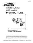
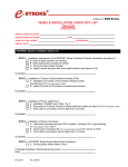
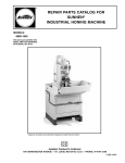
I-CH-103C
Installation, Setup
and Operation
INSTRUCTIONS
for
SUNNEN® HORIZONTAL HONE
Model CH-100
READ THE FOLLOWING INSTRUCTIONS THOROUGHLY AND CAREFULLY BEFORE UNPACKING,
INSPECTING, OR INSTALLING THE SUNNEN® HORIZONTAL HONE.
“SUNNEN AND THE SUNNEN LOGO ARE REGISTERED TRADEMARKS OF SUNNEN PRODUCTS COMPANY.”
SUNNEN ® PRODUCTS COMPANY • 7910 MANCHESTER ROAD • ST. LOUIS, MO 63143, U.S.A. • PHONE: 314-781-2100
GENERAL INFORMATION
The Sunnen® equipment has been designed and engineered for a wide variety of parts within the capacity and limitation of the equipment. With proper care
and maintenance this equipment will give years of service.
READ THE FOLLOWING INSTRUCTIONS CAREFULLY AND THOROUGHLY BEFORE UNPACKING, INSPECTING, OR INSTALLING THIS EQUIPMENT.
IMPORTANT: Read any supplemental instructions BEFORE installing this equipment. These supplemental instructions give you important information to
assist you with the planning and installation of your Sunnen equipment.
Sunnen Technical Service Department is available to provide telephone assistance for installation, programming, & troubleshooting of your Sunnen
equipment. All support is available during normal business hours, 8:00 AM to 4:30 PM Central Time.
Review all literature provided with your Sunnen equipment. This literature provides valuable information for proper installation, operation, and maintenance
of your equipment. Troubleshooting information can also be found within the Instructions. If you cannot find what you need, call for technical support.
Where applicable, programming information for your Sunnen equipment is also included. Most answers can be found in the literature packaged with your
equipment.
Help us help you. When ordering parts, requesting information, or technical assistance about your equipment, please have the following
information available:
• Have ALL MANUALS on hand. The Customer Services Representative or Technician will refer to it.
• Have Model Number and Serial Number printed on your equipment Specification Nameplate.
• Where Applicable: Have Drive model and all nameplate data. Motor type, brand, and all nameplate data.
For Troubleshooting, additional information may be required:
• Power distribution information (type - delta, wye, power factor correction; other major switching devices used, voltage fluctuations)
• Installation Wiring (separation of power & control wire; wire type/class used, distance between drive and motor, grounding).
• Use of any optional devices/equipment between the Drive & motor (output chokes, etc.).
For fast service on your orders call:
Sunnen Automotive Customer Service toll free at: 1-800-772-2878
Sunnen Industrial Customer Service toll free at: 1-800-325-3670
Customers outside the USA, contact your local authorized Sunnen Distributor.
Additional information available at: http://www.sunnen.com or e-mail: [email protected]
NOTE: Sunnen reserves the right to change or revise specifications and product design in connection with any feature of our products contained herein.
Such changes do not entitle the buyer to corresponding changes, improvements, additions, or replacements for equipment, supplies or accessories
previously sold. Information contained herein is considered to be accurate based on available information at the time of printing. Should any discrepancy of
information arise, Sunnen recommends that user verify the discrepancy with Sunnen before proceeding.
ESD PREVENTION REVIEW
Let's review the basics of a sound static control system and its effective implementation. First, in the three step plan:
1.
Always ground yourself when handling sensitive components or assemblies.
2.
Always use a conductive or shielded container during storage or transportation. These materials create a Faraday
cage which will isolate the contents from static charges.
3.
Open ESD safe containers only at a static safe work station.
At the static safe work station, follow these procedures before beginning any work:
A.
Put on your wrist strap or foot grounding devices.
B.
Check all grounding cords to make sure they are properly connected to ground, ensuring the effective dissipation of static charges.
C.
Make sure that your work surface is clean and clear of unnecessary materials, particularly common plastics.
D.
Anti-static bubble wrap has been included for use at the machine when an ESD safe workstation is not available.
You are now properly grounded and ready to begin work. Following these few simple rules and using a little common sense will go a long
way toward helping you and your company in the battle against the hazards of static electricity. When you are working with ESD sensitive devices, make sure you:
GROUND
ISOLATE
NEUTRALIZE
ii
SUNNEN® LIMITED PRODUCT WARRANTY
Sunnen® Products Company and its subsidiaries (SPC) warrant that all new SPC honing machines, gaging equipment, tooling, and related equipment will
be free of defects in material and/or workmanship for a period of one year from the date of original shipment from SPC.
Upon prompt notification of a defect during the one-year period, SPC will repair, replace, or refund the purchase price, with respect to parts that prove to be
defective (as defined above). Any equipment or tooling which is found to be defective from improper use will be returned at the customer's cost or repaired
(if possible) at customer's request. Customer shall be charged current rates for all such repair.
Prior to returning any SPC product, an authorization (RMA#) and shipping instructions must be obtained from the Customer Service Department or items
sent to SPC will be returned to the customer.
Warranty Limitations and Exclusions This Warranty does not apply to the following:
• Normal maintenance items subject to wear and tear: (belts, fuses, filters, etc).
• Damages resulting from but not limited to:
› Shipment to the customer (for items delivered to customer or customer's agent F.O.B., Shipping Point)
› Incorrect installation including improper lifting, dropping and/or placement
› Incorrect electric power (beyond +/- 10% of rated voltage) including intermittent or random voltage spikes or drops
› Incorrect air supply volume and/or pressure and/or contaminated air supply
› Electromagnetic or radio frequency interference from surrounding equipment (EMI, RFI)
› Storm, lightning, flood or fire damage
› Failure to perform regular maintenance as outlined in SPC manuals
› Improper machine setup or operation causing a crash to occur
› Misapplication of the equipment
› Use of non-SPC machines, tooling, abrasive, fixturing, coolant, repair parts, or filtration
› Incorrect software installation and/or misuse
› Non-authorized customer installed electronics and/or software
› Customer modifications to SPC software
THE LIMITED WARRANTY DESCRIBED HEREIN IS EXPRESSLY IN LIEU OF ALL ANY OTHER WARRANTIES. SPC MAKES NO REPRESENTATION OR WARRANTY OF ANY
OTHER KIND, EXPRESS OR IMPLIED, WHETHER AS TO MERCHANTABILITY, FITNESS FOR A PARTICULAR PURPOSE OR ANY OTHER MATTER. SPC IS NOT
RESPONSIBLE FOR THE IMPROPER USE OF ANY OF ITS PRODUCTS. SPC SHALL NOT BE LIABLE FOR DIRECT, INDIRECT, INCIDENTAL, OR CONSEQUENTIAL
DAMAGES INCLUDING BUT NOT LIMITED TO: LOSS OF USE, REVENUE, OR PROFIT. SPC ASSUMES NO LIABILITY FOR PURCHASED ITEMS PRODUCED BY OTHER
MANUFACTURERS WHO EXTEND SEPARATE WARRANTIES. REGARDLESS OF ANY RIGHTS AFFORDED BY LAW TO BUYER, SPC's LIABILITY, IF ANY, FOR ANY AND
ALL CLAIMS FOR LOSS OR DAMAGES WITH RESPECT TO THE PRODUCTS, AND BUYER'S SOLE AND EXCLUSIVE REMEDY THEREFORE, SHALL IN ALL EVENTS BE
LIMITED IN AMOUNT TO THE PURCHASE PRICE OF THAT PORTION OF THE PRODUCTS WITH RESPECT TO WHICH A VALID CLAIM IS MADE.
Shipping Damages
Except in the case of F.O.B., Buyer's destination shipments, SPC will not be liable for any settlement claims for obvious and/or concealed shipping damages.
The customer bears the responsibility to unpack all shipments immediately and inspect for damage. When obvious and/or concealed damage is found, the
customer must immediately notify the carrier's agent to make an inspection and file a claim. The customer should retain the shipping container and packing
material.
SUNNEN® SOFTWARE LICENSE AGREEMENT
This document is a Legal Agreement between you, as user and licensee (Licensee), and Sunnen® Products Company (SPC) with respect to preprogrammed
software (Software) provided by SPC for use on SPC Equipment. By using the Software, you, as Licensee, agree to become bound by the terms of this
Agreement.
In consideration of payment of the license fee (License Fee) which is part of the price evidenced by your receipt (Receipt), SPC grants to you as Licensee
a non-exclusive right, without right to sub-license, to use the particular copy of the SPC Software licensed hereunder only on the particular equipment sold with
the Software. SPC reserves all rights including rights not otherwise expressly granted, and retain title and ownership to the Software including all subsequent copies or updates in any media. The Software and all accompanying written materials are covered by copyrights owned by SPC. If supplied on
removable media (floppy disk), you, as Licensee, may copy the Software only for back up purposes; or you may request that SPC copy the Software for you
for the same purposes. All other copying of the Software or of the accompanying written materials is expressly forbidden and is in violation of the Agreement.
The Software and accompanying written materials (including the user's manual, if any) are provided in an "as is" condition without warranty of any kind
including the implied warranties of merchantability and fitness for a particular purpose, even if SPC has been advised of this purpose. SPC specifically does
not warrant that it will be liable as a result of the operation of the Software for any direct, indirect, consequential or accidental damages arising out of the
use of or inability to use such product even if SPC has been advised of the possibility of such use. It is recognized that some states do not allow the exclusion or limitation of liability for consequential or accidental damages and to the extent this is true, the above limitations may not apply.
Any alteration or reverse engineering of the software is expressly forbidden and is in violation of this agreement.
SPC reserves the right to update the software covered by this agreement at any time without prior notice and any such updates are covered by this
agreement.
iii
SAFETY INSTRUCTIONS
READ FIRST
This machine, like any equipment, may be dangerous if used improperly. Please
read all warnings and instructions before attempting to use this machine.
Always disconnect power at main enclosure before servicing machine.1
Always wear eye protection when operating this machine.
NEVER open or remove any machine cover or protective guard with power "ON."
Always disconnect power at main enclosure before servicing this equipment.1
DO NOT attempt any repair or maintenance procedure beyond those described in
this book. Contact your Sunnen® Field Service Engineer or Technical Services
Representative for repairs not covered in these instructions.
Due to the wide variety of machine configurations, all possibilities cannot be
described in these instructions. Instructions for safe use and maintenance of
optional equipment ordered through Sunnen, will be provided through separate
documentation and/or training provided by your Sunnen Field Service Engineer or
Technical Services Representative.
DO NOT attempt to defeat any safety device on this machine or on any of the
optional equipment.
If specially built automation components are added to this system, be sure that
safety is not compromised. If necessary, obtain special enlarged work area safety
system from Sunnen Products Co.
Indicates CE version ONLY.
1
DO NOT touch electrical components until main input power has been turned off and CHARGE
lamps are extinguished. WARNING: The capacitors are still charged and can be quite dangerous.
TABLE OF CONTENTS
Page
TABLE OF CONTENTS . . . . . . . . . . . . . . . . . . . . . . . . . . . . . . . . . . . . . . . . . . . . . . . . . . . . . . . . . . . . . . . . v
LIST OF APPENDIXES . . . . . . . . . . . . . . . . . . . . . . . . . . . . . . . . . . . . . . . . . . . . . . . . . . . . . . . . . . . . . . . . v
GENERAL INFORMATION & SPECIFICATIONS . . . . . . . . . . . . . . . . . . . . . . . . . . . . . . . . . . . . . . . . . vi
INTRODUCTION . . . . . . . . . . . . . . . . . . . . . . . . . . . . . . . . . . . . . . . . . . . . . . . . . . . . . . . . . . . . . . . . . . . . vii
FLOOR LAYOUT (Configuration) . . . . . . . . . . . . . . . . . . . . . . . . . . . . . . . . . . . . . . . . . . . . . . . . . . . . . . viii
INSTALLATION . . . . . . . . . . . . . . . . . . . . . . . . . . . . . . . . . . . . . . . . . . . . . . . . . . . . . . . . . . . . . . . . . . . . . . . 1
Purpose . . . . . . . . . . . . . . . . . . . . . . . . . . . . . . . . . . . . . . . . . . . . . . . . . . . . . . . . . . . . . . . . . . . . . . . . . . . . . .1
Tools & Materials . . . . . . . . . . . . . . . . . . . . . . . . . . . . . . . . . . . . . . . . . . . . . . . . . . . . . . . . . . . . . . . . . . . . . .1
Installation . . . . . . . . . . . . . . . . . . . . . . . . . . . . . . . . . . . . . . . . . . . . . . . . . . . . . . . . . . . . . . . . . . . . . . . . . . . .I
Electrical Connection . . . . . . . . . . . . . . . . . . . . . . . . . . . . . . . . . . . . . . . . . . . . . . . . . . . . . . . . . . . . . . . . . . .3
Filter Element . . . . . . . . . . . . . . . . . . . . . . . . . . . . . . . . . . . . . . . . . . . . . . . . . . . . . . . . . . . . . . . . . . . . . . . . .3
Tool Support . . . . . . . . . . . . . . . . . . . . . . . . . . . . . . . . . . . . . . . . . . . . . . . . . . . . . . . . . . . . . . . . . . . . . . . . . .3
PREPARING FOR OPERATION . . . . . . . . . . . . . . . . . . . . . . . . . . . . . . . . . . . . . . . . . . . . . . . . . . . . . . . . . .5
General . . . . . . . . . . . . . . . . . . . . . . . . . . . . . . . . . . . . . . . . . . . . . . . . . . . . . . . . . . . . . . . . . . . . . . . . . . . . . .5
Theory of Operation . . . . . . . . . . . . . . . . . . . . . . . . . . . . . . . . . . . . . . . . . . . . . . . . . . . . . . . . . . . . . . . . . . . .5
Major Components . . . . . . . . . . . . . . . . . . . . . . . . . . . . . . . . . . . . . . . . . . . . . . . . . . . . . . . . . . . . . . . . . . . . .5
Controls . . . . . . . . . . . . . . . . . . . . . . . . . . . . . . . . . . . . . . . . . . . . . . . . . . . . . . . . . . . . . . . . . . . . . . . . . . . . . .5
Hone Unit . . . . . . . . . . . . . . . . . . . . . . . . . . . . . . . . . . . . . . . . . . . . . . . . . . . . . . . . . . . . . . . . . . . . . . . . . . . .7
OPERATION . . . . . . . . . . . . . . . . . . . . . . . . . . . . . . . . . . . . . . . . . . . . . . . . . . . . . . . . . . . . . . . . . . . . . . . . . .9
General . . . . . . . . . . . . . . . . . . . . . . . . . . . . . . . . . . . . . . . . . . . . . . . . . . . . . . . . . . . . . . . . . . . . . . . . . . . . . .9
Safety Precautions . . . . . . . . . . . . . . . . . . . . . . . . . . . . . . . . . . . . . . . . . . . . . . . . . . . . . . . . . . . . . . . . . . . . . .9
Honing Hints . . . . . . . . . . . . . . . . . . . . . . . . . . . . . . . . . . . . . . . . . . . . . . . . . . . . . . . . . . . . . . . . . . . . . . . . . .7
Setup . . . . . . . . . . . . . . . . . . . . . . . . . . . . . . . . . . . . . . . . . . . . . . . . . . . . . . . . . . . . . . . . . . . . . . . . . . . . . . . .9
Operation . . . . . . . . . . . . . . . . . . . . . . . . . . . . . . . . . . . . . . . . . . . . . . . . . . . . . . . . . . . . . . . . . . . . . . . . . . . . .9
ROUTINE MAINTENANCE . . . . . . . . . . . . . . . . . . . . . . . . . . . . . . . . . . . . . . . . . . . . . . . . . . . . . . . . . . . .15
General . . . . . . . . . . . . . . . . . . . . . . . . . . . . . . . . . . . . . . . . . . . . . . . . . . . . . . . . . . . . . . . . . . . . . . . . . . . . .15
Cleaning . . . . . . . . . . . . . . . . . . . . . . . . . . . . . . . . . . . . . . . . . . . . . . . . . . . . . . . . . . . . . . . . . . . . . . . . . . . .15
Lubrication . . . . . . . . . . . . . . . . . . . . . . . . . . . . . . . . . . . . . . . . . . . . . . . . . . . . . . . . . . . . . . . . . . . . . . . . . .15
Coolant Level . . . . . . . . . . . . . . . . . . . . . . . . . . . . . . . . . . . . . . . . . . . . . . . . . . . . . . . . . . . . . . . . . . . . . . . .16
Coolant Reservoir . . . . . . . . . . . . . . . . . . . . . . . . . . . . . . . . . . . . . . . . . . . . . . . . . . . . . . . . . . . . . . . . . . . . .16
Filter Canister . . . . . . . . . . . . . . . . . . . . . . . . . . . . . . . . . . . . . . . . . . . . . . . . . . . . . . . . . . . . . . . . . . . . . . . .16
Filter Element . . . . . . . . . . . . . . . . . . . . . . . . . . . . . . . . . . . . . . . . . . . . . . . . . . . . . . . . . . . . . . . . . . . . . . . .17
Hone Unit . . . . . . . . . . . . . . . . . . . . . . . . . . . . . . . . . . . . . . . . . . . . . . . . . . . . . . . . . . . . . . . . . . . . . . . . . . .19
Cradle Drive Chain . . . . . . . . . . . . . . . . . . . . . . . . . . . . . . . . . . . . . . . . . . . . . . . . . . . . . . . . . . . . . . . . . . . .19
TROUBLESHOOTING . . . . . . . . . . . . . . . . . . . . . . . . . . . . . . . . . . . . . . . . . . . . . . . . . . . . . . . . . . . . . . . . .21
General . . . . . . . . . . . . . . . . . . . . . . . . . . . . . . . . . . . . . . . . . . . . . . . . . . . . . . . . . . . . . . . . . . . . . . . . . . . . .21
Operational Troubleshooting Index . . . . . . . . . . . . . . . . . . . . . . . . . . . . . . . . . . . . . . . . . . . . . . . . . . . . . . . .21
APPENDIXES
A Check List, Setup & Operation . . . . . . . . . . . . . . . . . . . . . . . . . . . . . . . . . . . . . . . . . . . . . . . . . . . . . . . . . 21
B Check List, Work Cycle Sequence . . . . . . . . . . . . . . . . . . . . . . . . . . . . . . . . . . . . . . . . . . . . . . . . . . . . . . . 23
“SUNNEN® IS A REGISTERED TRADEMARKS OF SUNNEN PRODUCTS COMPANY.”
© Copyright 2006 by Sunnen® Products Company • Printed in U.S.A.
v
GENERAL INFORMATION & SPECIFICATIONS
Sunnen Horizontal (Line) Hone - Model CH-100
Work Capacity*:
V-blocks, both 60 & 90; angle head blocks;
overhead & L-head in-line blocks; Up to
45 L x 28 W x 28 in. from head deck to main brg.
centerline (1140 x 710 x 710 mm)
Workpiece Weight*:
Diameter Range(ID)*:
(Main Bearing Bore)
Stroke Length*:
Motor:
Coolant Capacity
Minimum:
Maximum:
Coolant Requirements:
1.800 to 7.000 in. (46 - 178 mm)
Note: Special tooling is required above 5 in. (127 mm)
26 in. (660 mm) Max.
1.5 HP (2,0 kW)
35 gal. (132 liters)
55 gal. (207 liters)
Sunnen CK-50 Honing Oil
Note: Use MAN-845 when honing aluminum
Electrical Requirements: 115/230 V, 1 Ph, 60 Hz; 220 V, 1 Ph, 50 Hz
(See Motor Plate)
Shipping Weight: 1650 lbs. (750 kg)
Floor Weight: 1450 lbs. (660 kg)
Color:
Pearl Gray / Pewter Gray / Burgundy Trim
vi
INTRODUCTION
This Instruction Manual provides information required to install, operate, and maintain the Sunnen® CH-100
Horizontal Hone.
When ordering parts for, or requesting information about your unit, include the serial numbers of both your kit
and your machine.
READ THE FOLLOWING INSTRUCTIONS THOROUGHLY BEFORE UNPACKING, INSPECTING, OR
INSTALLING THE SUNNEN® CH-100 HORIZONTAL HONE.
MAXIMUM OVERALL DIMENSIONS OF ENGINE BLOCKS FOR
WHICH SUNNEN CH-100 HORIZONTAL (LINE) HONE IS DESIGNED.
28 in.
(711 mm)
MAIN BEARING
CENTERLINE
V-TYPE BLOCKS:
45 in. (1143) Long
28 in. (711) Wide
28 in. (711 mm) Top Surface to Main Bearing Centerline
28 in.
(711 mm)
IN-LINE BLOCKS:
45 in. (1143) Long
28 in. (711) Wide
28 in. (711 mm) Head Surface to Main Bearing Centerline
HEAD SURFACE
MAIN BEARING BORE Roundness Accuracy: .0005 in. (0,0125 mm)
Alignment Accuracy: .0005 in. (0,0125 mm)
28 in.
(711 mm)
MAIN BEARING
CENTERLINE
TOP
SURFACE
28 in.
(711 mm)
OPERATOR
Scale:
1/4 in. = 1 ft.
1 mm = 48 mm
OUTLINE LAYOUT
viii
FIGURE 1-A, Floor Plan - Sunnen® Tube Hone
ADJUSTABLE
MAX. TRAVEL
7 in. (178 mm)
LOWEST
CRADLE
POSITION
30 in. (760 mm)
APPROXIMATE TRAVEL
72 in. (1830 mm)
SIDE VIEW
42.5 in. (1080 mm)
MAX. TRAVEL
15 in. (380 mm)
ADJUSTABLE
Floor Loading:
Less than 90 lbs/sf (440 kg/sm).
Weight Installed:
Approximately 170 lbs. (770 kg) including coolant.
WORK AREA
98 in. (2490 mm)
MAX. STROKE LENGTH
26 in. (660 mm)
138 in. (3500 mm)
45 in. (1140 mm)
FRONT VIEW
53.875 in. (1368 mm)
TOP VIEW
DOOR OPENING
48 in. (1220 mm)
MAX. BLOCK LENGTH
18.125 in.
(460 mm)
DRIP TRAY
REMOVABLE
66 in. (1676 mm)
41.125 in. (1048 mm)
50 in. (1270 mm)
MIN. DOOR OPENING
24 in. (610 mm)
MAX. TRAVEL
SECTION 1
INSTALLATION
GENERAL
NOTE: When ordering parts for, or requesting
information about your Hone, include model and
serial number printed on machine nameplate.
Consult this section when unpacking, inspecting and
installing Sunnen® CH-100 Horizontal Hone.
Hereafter, referred to as the Hone (see Figure 1-1).
1. Remove bolts from around base of shipping carton.
TOOLS & MATERIALS
2. Remove staples and lift off top of carton.
The following list of suggested tools and materials
are needed for unpacking and installing your Hone.
Knife
Wire Cutter/Stripper
Hammer
Screwdriver (Std. Nose)
Crow Bar
Slip-Joint Pliers
Tin Snips
Open End Wrenches
Hew Wrenches
Cleaning Solvent
3. Cut down side of carton and remove.
CAUTION
DO NOT remove Leveling Bolts.
4. Remove four (4) Bolts securing Hone to skid,
using 1/2" Open End Wrench.
INSTALLATION
CAUTION
Use care when lifting and moving Hone.
Approximate weight of Hone is 1450 lbs (660 kg).
Read the following instructions carefully and
thoroughly before unpacking and inspecting your
Hone. All references to right and left in these
instructions are, unless otherwise noted, are as one
looks at Hone or assembly being described (refer to
Figure 1-1).
5. Lift Hone from skid, using a Forklift. Insert
forks under rear of Hone as shown (see Figure 1-2).
Forks MUST be long enough to support Hone on
both sides (approximately 48 in/1220 mm). Forks
should be position under Hone from rear as shown.
6. Move Hone to staging area.
7. Remove Crank Handle, which is strapped to
Cradle Assembly (see Figure 1-3).
8. Place Handle in slot in top of Hone and engage
Elevating Screw.
9. Loosen Cradle Lock Screw and raise Cradle by
turning Handle clockwise.
RIGHT
10. Remove components packaged in base of Hone.
LEFT
11. Remove any remaining packing material.
FRONT
12. Inspect Hone and components for dents, scratches,
or damage resulting from improper handling by
carrier. If damage is evident, immediately file a claim
with carrier.
FIGURE 1-1, Sunnen Horizontal Hone
CRANK
HANDLE
CRADLE
FIGURE 1-2, Shipping Crate
FIGURE 1-3, Cradle Assembly
1
13. Unpack boxes packaged with your Hone and
check all items against enclosed packing list. Notify
Sunnen Products Company of any missing or damaged items.
JAM
NUT
LEVELING
BOLT
CAUTION
Use care when lifting and moving Hone.
Approximate weight of Hone is 1450 lbs (750 kg).
14. Move Hone to desired.
LEVELING
BOLT
NOTE: Hone should be located on a leveled concrete
floor. Allow space around Hone to give operator
room to service the Hone (refer to Figure 1-A). There
should be an overhead track and chain fall located
over the Hone to aid in block installation. If no
overhead track is available, allow ample space for
use of a portable hoist-stand for heavy lifting.
PLATE
FIGURE 1-4, Leveling Bolts
14. Level Hone by adjusting Leveling Bolts in Base
(see Figure 1-4).
Level Hone both left to right and front to back,
using a machinist level. Tighten all Jam Nuts.
DRIP
TRAY
15. Attach Drip Tray by sliding over top channel on
right side of Hone (see Figure 1-5).
16. After unpacking and installing your Hone, clean
and lubricate (refer to Section 4).
FIGURE 1-5, Drip Tray
17. Fill Coolant Reservoir with 35 to 55 gallons
(132-207 liters) of Sunnen Coolant, by pouring
directly into reservoir.
ELECTRICAL
CONTROL
PANEL
NOTE: It is recommended that you use only Sunnen
full strength Sunnen CK-50 Honing Oil.
ELECTRICAL REQUIREMENTS
All wiring is to be performed by a competent, Licensed
Electrician in accordance with all local, state, and
federal codes and regulations; along with any special
information provided on machine nameplate or
electrical specification plate.
FIGURE 1-6, Electrical Enclosure
WARNING
All wiring and electrical equipment service should
be performed by authorized personnel ONLY.
MASTER
ON/OFF
SWITCH
CAUTION
Note model electrical supply cord requirement
printed on machine nameplate or electrical
specification plate. Do not attempt to connect
machine if supply voltage is not within following
acceptable limits as noted on nameplate or electrical
specification plate. If supply voltage is not within
these limits MACHINE WILL BE DAMAGED.
Verify supply voltage is same as voltage on Machine
Nameplate or Electrical Specifications Plate.
If supply voltage does not match voltage stated on
Electrical Specification Plate but is within acceptable
limits, electrical connection can proceed but Machine
Conversion below will be necessary.
POWER
CORD
GRN
WHT
for 115V/60Hz
BLK
(GND) PE
TERMINAL
DISCONNECT
BLOCK
for 220V/50Hz
& 230/60Hz
FIGURE 1-7, Electrical Connection
2
230V UNIT
115V UNIT
Outlet for 230 volt unit should look like the following.
Outlet for 115 volt unit should look like the following.
ADAPTER
GROUNDING
SCREW
PROPER
OUTLET
GROUNDING PIN
GROUNDING PIN
Electrical supply cord is equipped with a grounding type plug.
Make sure unit is connected to an outlet having the same
configuration as the plug. No adapter is available or should be
used with this unit. If the unit MUST be reconnected for use
on a different type of electrical circuit, the reconnection
should be made by a qualified electrician.
Electrical supply cord is equipped with a grounding pin.
A temporary adapter, may be used to connect this plug to a
2-pole receptacle, if a properly grounded outlet is not
available. Temporary adapter should ONLY be used until a
properly grounded outlet can be installed by a qualified
electrician. Green-colored rigid ear, lug, etc., extending from
adapter MUST be connected to a permanent ground, such as a
properly grounded outlet box.
Unit wiring should comply with all local, state, and federal
codes and ordinances.
Unit wiring should comply with all local, state, and federal
codes and ordinances.
FIGURE 1-8, Electrical
ELECTRICAL CONNECTION
unlock doors to Electrical Control Enclosure using
key supplied with machine. Door(s) to enclosure is
equipped with Key-Lock Safety Latches.
For models with Cords: The Hone is a 115/230V, 1Ph,
60Hz. or 220V, 1Ph, 50Hz. machine. Make electrical
connections as follows (see Figures 1-6 & 1-8):
WARNING
Residual Voltage exists for 2-3 minutes after
Master ON/OFF Switch is turned OFF. Before
working inside Enclosure, wait for all fans to stop
running to allow drives to discharge.
NOTE: In some cases, Hone may be direct wired to
power source. All wiring is to be performed by a
qualified person and in accordance with all local,
state, and federal codes and regulations.
1. Ensure that Oil Pump and Master Control
Switches are in their OFF positions.
2. Turn Master ON/OFF Switch to OFF position and
open Doors. (Doors WILL NOT open unless Master
ON/OFF Switch is in OFF position.)
2. Connect Electrical Supply Cord, on side of
Electrical Control Panel, to properly polarized and
grounded receptacle (refer to Figure 1-8).
WARNING
You must use hole provided. Drilling any new holes in
electrical enclosure may void machine warranty.
3. If not provided: Remove hole plug from entrance
hole in enclosure and install an approved oil tight fitting.
4. Insert Electrical Supply Cord through Oil Tight
Fitting and route to Electrical Disconnect Block.
Allow for approximately 600 mm of cable from
where it enters Enclosure; then cut off excess.
5. Strip 254 mm (10 in.) off cable's outer jacket.
6. Strip 6 mm (1/4 in.) of insulation off each wire.
7. If applicable: Connect Green Wire (GRN) to PE
Terminal on Electrical Disconnect Block.
8. Connect White Wire as noted in figure (refer to
Figure 1-7).
9. Connect other three wires to Disconnect Block
as noted in figure (refer to Figure 1-7).
10. Route and secure Cord inside of Enclosure.
11. Tighten Oil Tight Fitting.
For models without Cords: A pre-drilled hole with
an Oil Tight Fitting has been provided in Electrical
Enclosure for Electrical Supply Cord (not supplied).
Connect Cord as follows (see Figures 1-7 & 1-8).
NOTE: For Cord dimensions refer to General
Information & Specification at front of this manual.
CAUTION
Doors are equipped with lockable Safety Door
Latches. Doors should be closed and latched during
operation to prevent accidental interruption of
operation from doors being opened. Doors Latches
should be Locked-Out and Tagged during servicing
to prevent machine from being powered up.
1. If applicable: Loosen Safety Latches on door(s) to
enclosure, using a screwdriver. Or, on CE models,
3
12. Close and secure/lock Door(s) to Enclosure.
13. Route and connect Electrical Supply Cord to
power source. Plug Cord into a properly polarized
grounding-type wall receptacle (refer to Figure 1-8).
14. Turn ON Master ON/OFF Switch.
HEX NUT (2)
LOCKWASHER (2)
HONE SUPPORT
INSTALL TOOL SUPPORT
Attach optional Sunnen CH-600 Tool Support, using
holes provided on left end of Hone and hardware
provided (see Figure 1-9).
3/8” HEX HEAD
CAPSCREW (2)
FIGURE 1-9, Tool Support
VALVE BODY
ASSEMBLY
SPRING CLIPS
OIL SPOUT
ASSEMBLY
CRANK
HANDLE
HARDWOOD
BLOCK
DRIP TRAY
STOP PLATES
GAGE
BRACKET
OIL
PUMP
THREADED
ROD
OIL PUMP
INDICATOR
NUT
CRADLE
ASSEMBLY
CLAMPING
BAR
CARRIAGE
& TORQUE
ASSEMBLY
PAN
RISER
BLOCKS
DRILL
ASSEMBLY
CLAMP
PLATE
FIGURE 2-1, Major Components
COOLANT PUMP
SWITCH
START
(COOLANT
PUMP)
START
(COOLANT
PUMP)
STOP
(COOLANT
PUMP)
COOLANT
PUMP
INDICATOR
FIGURE 2-2, Controls
4
SECTION 2
PREPARING FOR OPERATION
GENERAL
Valve Body Assembly: Automatically shuts off
coolant when coolant spout assembly is raised.
Clamp Plate: Permits coolant spout assembly to be
raised or lowered.
Hardwood Blocks: Protects hone cabinet when
removing hone unit.
Toot Support, optional: Provides support when
loading or unloading hone unit into or out of Hone.
Hone Driver: Controls cutting pressure and stone
feed-up.
Drill Assembly: Supplies power to turn hone unit.
Lock Arm: Locks drill assembly in home position;
releases so drill assembly can be placed in stored
position.
Carriage & Torque Assembly: Supports drill
assembly and provides stroking capability.
Mandrel Wrench: Used to position wedge and lock
hone unit in hone driver.
Wrench Socket: Used to tighten or loosen clamping
nut on cradle.
Consult this section when preparing Machine for
operation.
MAJOR COMPONENTS
For locations and function of major components on
your Hone, see Figure 2-1.
Stop Plates: Set to stroke position and limits stroke
length.
Drip Tray: Catches oil runoff on left side of Hone
and returns it to Coolant Reservoir.
Cradle Assembly: Adjusts to accommodate engine
blocks of almost any size or configuration. Moves
up or down to permit alignment of main bearing
bores and drill assembly.
Riser Blocks: Adjustable for holding engine block.
Clamping Bar: Holds engine block down.
Threaded Rod: Used with clamping bar to hold
engine block down.
Clamping Nut: Secures clamping bar.
Gage Bracket: Holds optional Dial Bore Gage.
Drip Pan: Catches oil runoff on right side of Hone.
Crank Handle: Used to adjust height of cradle
assembly.
Coolant Spout Assembly: Directs coolant to
workpiece.
Spring Clips: Enables unneeded coolant outlets to
be sealed off.
CONTROLS
For locations and function of controls on your Hone,
see Figure 2-2 and Table 2-1.
SAFETY SYMBOLS
For a description of safety symbols used on this
machine refer to Table 2-2.
TABLE 2-2, Operator Controls (Buttons & Switches)
SYMBOL
DESCRIPTION
FUNCTION
START
(COOLANT
PUMP)
Black
Pushbutton
Switch
Turns power ON to Coolant Pump.
STOP
(COOLANT
PUMP)
Red
Pushbutton
Switch
Turns power OFF to Coolant Pump.
COOLANT
PUMP
INDICATOR
Indicator
Light
(Green)
(DRILL
ASSEMBLY)
Trigger
Switch
Turns power ON to Drill Motor when trigger is
depressed. Shuts OFF power to Drill when trigger
is released.
(VALVE BODY
ASSEMBLY)
Flow Control
Valve
Automatically turns ON coolant flow when coolant
spout assembly is lowered. Shuts OFF coolant
when assembly is raised.
Indicates when power is being
supplied to Coolant Pump.
5
TABLE 2-2, Safety Symbols
SYMBOL
DESCRIPTION
FUNCTION
Warning Label
Warns that an electrical hazard exists.
Warning Label
Warns that safety glasses should be worn at all times when operating
this machine.
Warning Strip
Warns that a physical hazard exists, and that proper precautions should
be taken.
Label
Designates this machine is “CE” compliance.
Warning
Label
Warns not to hold workpiece in hand without a torque
resisting fixture.
SELECT HONE UNIT
Generally, for every two inches of engine block
length, one stone is required in Hone Unit. Select
Hone Unit, stones and shoes according to Tables 2-3
and 2-4 or refer to Sunnen Engine Rebuilding Catalog.
If you find that you must use a quantity of stones
and shoes other than those shown in Tables, you
will have to use blank spacers in place of stones and
shoes because tension blocks can only be installed
to accommodate quantity of stones and shoes shown
in Tables. A spacer for stones consist of a stoneholder
with abrasive stone removed. A spacer for shoes
consist of worn or filed-down shoes. Whenever stones
and shoes need to be replaced, change all stones and
shoes at one time. There must always be a pair of shoes
opposite each stone. Do not mix stones and shoes
between sets. Once you use a set of stones and shoes
in a Hone Unit, do not use in a different Hone Unit.
IMPORTANT
If you intend to use these stones again, mark them so
they can be replaced in same order.
HONE UNIT
IMPORTANT
If you intend to use these shoes again, mark them so
they can be replaced in same order and store with
stones.
3. Remove stones by pulling each one up and
toward drive end of unit.
4. Install new stones.
5. Insert Tension Block into unit.
6. Lightly snug Set Screw.
7. Using a piece of wood, lightly tap Block to set
stone. Then tighten Screw.
NOTE: There should be no back or forward
movement of stones. If there movement, loosen
screw and repeat step 6.
8. Repeat steps 2 thru 7 for replacing shoes.
Assemble Hone Unit as follows (see Figure 2-3):
1. Select Hone Unit, stones and shoes.
2. Loosen Screw and remove Tension Block from
slot on stone side of unit.
TABLE 2-3, 10RY Series Hone Units
Number of
Stoneholders &
Shoes
BLOCK LENGTH
6
12 to 15 in (305 to 381 mm)
8
15 to 18 in (381 to 457 mm)
10
18 in (457 mm) or More
10RY
TABLE 2-4, 15RY Series Hone Units
Number of
Stoneholders &
Shoes
15RY
BLOCK LENGTH
11
22 to 26 in (559 to 660 mm)
13
26 to 30 in (660 to 762 mm)
15
30 in (762 mm) or More
FIGURE 2-3, Hone Unit
6
SECTION 3
SETUP & OPERATION
GENERAL
• If you ignore these three defects when rebuilding
an engine, a hard turning or binding crankshaft is
result. This binding robs engine of horsepower and
quickly wears inserts ... or seizes and spins new
inserts, which results in scored main bearing bore
housings, and often a broken crankshaft.
• In past correcting or even checking main bearing
bores for alignment and size has been time consuming
for even most highly skilled machinists. Often, main
bearing bore misalignment is detected when crankshaft and new inserts are installed ... necessitating
tearing down engine again, correcting problem,
reassembling, and maybe replacing inserts because
they were damaged during this assembly attempt.
• An engine with a crankshaft, which barely turns,
will have a short life at best. Good reputations and
sales are not built this way.
• With Sunnen CH Horizontal Hone Drive Unit, you
can line hone main bearing bores of average passenger
car block easily and quickly. This makes it practical
to line hone every block without wasting your time
checking to determine whether block needs to be
corrected or not. In addition, you'll be sure that
every block meets manufacturers' tolerances for
alignment, roundness and size.
• Line honing main bearing bores using revolutionary
Sunnen method is relatively easy. It provides ultimate
in accuracy for blue-print needs of high performance
engine builders, yet offers speed required of jobber
shops and volume rebuilders for lower operating
costs. Sunnen Hone Units are available to cover
diameter range from 1.8 to 5.0 in. (61-127 mm),
giving every shop capability to line hone truck
blocks as well as smallest passenger car blocks
quickly, easily, and profitably.
This section describes a step-by-step operating
procedure for your Hone.
SAFETY PRECAUTIONS
The following precautions should be followed to
ensure maximum safety of personnel while working
on or around Hone.
• Ensure area is clear of other personnel before
operating Hone.
• Keep loose tools and other foreign objects clear of
Hone.
• Wear proper Safety items such as, safety glasses
and other personal safety equipment as necessary or
required.
• DO NOT wear loose fitting clothes or jewelry
while working on or around Hone.
• Keep area around Hone free of paper, oil, water
and all other debris at all times.
• Turn OFF electrical power when performing
service not requiring power.
• When lifting part or tooling use proper lifting
procedures or equipment.
THEORY OF OPERATION
There are three primary reasons why main bearing
bores require line honing.
1. When an engine is run for thousands of miles,
stresses of heating and cooling of block cause block
warpage and distortion; which causes misalignment
of main bearing bore. Because warpage takes place
over a long period, original main bearing inserts
compensate for warpage through wear. However,
when installing new inserts in warped block this
misalignment, even though slight, is all that is
needed to cause crankshaft to bind and quickly wear
out new inserts.
HONING HINTS
Prior to installing engine block in Hone, ensure that
following steps have been completed, as required.
True Stones & Shoes: When using a hone unit with
new stones and shoes, true in hone unit on a scrap
block. Follow same the honing procedures as outlined
in below, except use honing oil intermittently. Use just
enough oil to keep stones from becoming clogged.
Grind Caps: Note to volume rebuilders. Main bearing
caps can be removed, ground, and reinstalled at another
work station before putting block into Hone to keep
from trying up Hone while caps are being ground. To
schedule your production this way and grind caps
before installing block in Hone, proceed as follows:
2. High loads generally cause main bearing caps to
become larger in vertical direction (called stretch),
and to pinch in at parting line. Again, as in reason 1,
Original main bearing inserts compensate for cap
stretch through excessive wear. Thus, installing new
inserts in a block with stretched caps will cause
crankshaft to bind and again prematurely wear out
new inserts.
3. When excessive heat is generated, bearing may
seize to crankshaft and spin with it, scoring main
bearing bore housing.
7
• Remove all Bearing Caps. Mark caps and engine
block to ensure caps are reinstalled in their original
locations. Remove all burrs from main bearing web
and cap parting surfaces with a fine file. Wipe surfaces clean.
• Grind Bearing Caps on Sunnen CRG-750 Cap &
Rod Grinder, CRG-2000 Cap Angle Grinder, or
Sunnen CG-2400 Cap Grinder.
RISER BLOCKS
(RISERS CAN BE INVERTED TO FIT
DIFFERENT SHAPED ENGINE BLOCKS)
SETUP & OPERATION
To hone main bearing bore, proceed as follows:
1. Turn OFF power to Hone.
2. Swing Oil Control Unit into position. Leave
Oiler in up position.
FIGURE 3-1, Position Riser Blocks
3. Raise Front Door Panels to clear latches and
slide Door down into Hone.
4. Install V-type engine block in cradle. - Position
Riser Blocks to accept V-type engine block (see
Figure 3-1). Blocks may be positioned to accept
either 60' or 90' engine block.
NUT
THREADED
CLAMP ROD
CAUTION
To protect Cam Bearing Bores, Pad Bores with shop
towels before inserting Clamp Bar.
• Remove End Caps from Cam Bearing Bores and
insert Clamp Bar into engine block.
• Load engine block on Cradle; engage Threaded
Clam p Rods with slots in Clamp Bar; then tighten
Nuts (see Figure 3-2).
FIGURE 3-2, V-Type Engine Block
RISER
BLOCKS
5. Install in-line engine block in cradle.
• Place Riser Blocks so flat side is up to accept
in-line engine block (see Figure 3-3).
• Load engine block on Cradle by aligning Clamp
Rods with center of two cylinders and lower block
into position on Cradle.
• Secure engine block by installing Clamping Straps
and Nuts (see Figure 3-4).
6. If Bearing Caps have not previously been
ground, proceed as follows:
• Remove all Bearing Caps. Mark Caps and Engine
Block to ensure caps are reinstalled in their original
locations.
• Remove all burrs from Main Bearing Web and
Cap parting surfaces with a fine file. Wipe surfaces
clean.
• Grind Bearing Caps on Sunnen CRG-750 Cap and
Rod Grinder or CG-2400 Cap Grinder.
FIGURE 3-3, Position Riser Blocks
THREADED
CLAMP RODS
JAM NUTS
7. Assemble Hone Unit. (Refer to section 2, or to
instructions packaged with Unit.)
CLAMPING
STRAPS
8. Fully retract shoes on Hone Unit, by inserting
Key in Slot in end of Unit and turning it
counterclockwise (see Figure 3-5). Remove Key.
FIGURE 3-4, In-Line Engine Block
8
9. Check centerline (see Figure 3-6) of main bearing bores, using a Depth Micrometer to check both
block bearing bores and bearing caps.
HONE
UNIT
IMPORTANT
Some blocks have their main bearing bores machined
off center; so that centerline of bores MUST be
checked and hone unit centered in bores before bores
can be resized.
KEY
• If block bearing bores are within .005 inch of half
overall bore diameter go to step 10.
• If block bearing bores are greater than or less than
half overall bore diameter by more than .005 inch
go to step 11.
FIGURE 3-5, Retract Shoes
WARNING
Wear gloves or use shop towels when loading or
unloading hone unit to prevent personal injury.
CENTERED
10. Center hone unit using Centering Pins Method
(see Figure 3-7):
• Lay hone unit in main bearing bore, so stones are
pointed up.
• Insert Centering Pins (provided with hone unit)
into Centering Holes in unit.
• Position hone unit so Pins rest on Center Web
(bore) in block, with an odd number of webs; or on
either of Center Webs in engine blocks with an even
number of webs. Hone unit can now be rocked
lengthwise, pivoting on Centering Pins.
• Insert key in slot in end of unit.
• While rocking unit on Centering Pins, expand shoes
by turning key clockwise until unit will not rock.
• Remove key and Center Pins.
• Remove hone unit from main bearing bores.
• Reinstall and torque bearing caps on block.
LOW
CENTERLINE
HIGH
CENTERLINE
FIGURE 3-6, Centerline
CENTERING
PINS
WARNING
Wear gloves or use shop towels when loading or
unloading hone unit to prevent personal injury.
11. Center hone unit using Dial Indicator Method
(see Figure 3-8):
• Reinstall and torque bearing caps on engine block.
• Using Tool Support, slide hone unit in main bearing
bore, so stones are pointed up.
• Mount Dial Indicator (not supplied) on engine
block with Indicator Tip on end of hone unit .
• Insert key in slot in end of hone unit.
• While slowly rotating unit by hand, alternately
expand stones and shoes until run-out is eliminated.
Unit should run concentric to within .005 inch Total
Indictor Reading (TIR).
FIGURE 3-7, Centering Pin Method
MAGNETIC
BASE
A
B
DIAL
INDICATOR
DIAL
INDICATOR
STONE
FEED-UP
KNOB
HONE
UNIT
ENGINE
BLOCK
NOTE: Expand Shoes by turning Key clockwise and
expand stones by turning Stone Feed-Up Knob
clockwise.
FIGURE 3-8, Dial Indicator Method
9
• Remove Key and Dial Indicator.
• Slide Hone Unit from main bearing bores.
12. Measure diameters of main bearing bores.
WARNING
Wear gloves or use shop towels when loading or
unloading hone unit to prevent personal injury.
13. Slide Hone Unit into main bearing bore, so
stones are pointing up (see Figure 3-9):
• Loosen Clamp Handle and roughly align Tool
Support with main bearing bore. Retighten Handle.
• Lay front end of hone unit on Roller, so shoes rest
on roller.
• Lift drive end of hone unit and slide on roller into
main bearing bore.
• Loosen Clamp Handle and lower roller, until it
rest on Clamp Bracket.
FIGURE 3-9, Insert Hone Unit
CRANK
HANDLE
WARNING
DO NOT operate Horizontal Hone with Tool
Support Roller still in contact with Hone Unit.
14. Adjust height of Cradle, for type and size of
block to be honed (see Figure 3-10):
• Loosen Cradle Clamp.
• Adjust Cradle height, using Crank Handle. Turn
handle clockwise to raise cradle and counterclockwise to lower cradle.
CRADLE
LOCK
SCREW
FIGURE 3-10, Cradle Height
NOTE: Centerline of main bearing bore should be in
approximate alignment with centerline of Quick
Coupler as illustrated.
PINS
HONE
DRIVER
• Tighten Cradle Clamp.
QUICK
RELEASE
LEVER
15. Connect Hone Driver to Quick Coupler (see
Figure 3-11). Align Cross Pins on Driver with Slot
in Coupler; push Driver in Slot and turn clockwise
to lock in place.
16. Set Overstroke as follows (see Figure 3-12):
• Loosen Stroke Stops.
QUICK
COUPLER
NOTE: On blocks with three Main Bearing Webs,
position Hone Unit as shown. Stones should always
remain in contact with webs.
PINS
HONE
DRIVER
FIGURE 3-11, Quick-Coupler
STROKE LENGTH
• On blocks with four or more Main Bearing Webs,
position Hone Unit as shown. Hone Unit should be
stroked past end webs as shown.
• Move Overarm to left to set overstroke at left end
of stroke. Move Left Stroke Stop against Drag
Control and tighten securely.
• Move Overarm to right to set overstroke at right
end of stroke. Move Right Stroke Stop against Drag
Control and tighten securely.
OVERSTROKE
(SET EQUAL
OVERSTROKE ON
OTHER END)
END OF STROKE, DON’T STROKE ANY
FURTHER TOWARD YOU
OVERSTROKE
(SET EQUAL
OVERSTROKE ON
OTHER END)
STONE MAY LEAVE
END OF WEB
17. Adjust Cutting Pressure, so stones will
automatically advance during honing operation, as
follows (see Figure 3-13):
FIGURE 3-12, Overstroke
10
20. Push machine's START Lever to turn on oil.
CHUCK
WRENCH
STONE
FEED-UP
KNOB
ZERO
“0”
21. Lower Oil Control into operating position,
which will automatically turns oil flow on, and
adjust Spring Clips to provide an even flow of oil to
Main Bearing Web. To adjust volume of oil flow,
use Oil Flow Valve on Hone's Oil Nozzle.
WITNESS
MARK
22. Stand behind Drive Motor, gripping Carriage and
Motor Handle. Depress button on Handle to turn
Drive Motor ON; then manually stroke bore with a
even back and forth motion to pre-set stroke stops.
CUTTING PRESSURE
CONTROL DIAL
FIGURE 3-13, Cutting Pressure
NOTE: If bearing bores are on minimum size and
caps are not ground, hone for 10 to 20 seconds. If
caps are ground about .002 in. (0,05 mm), hone
approximately 40 seconds.
23. Release button on Handle to STOP honing.
24. Turn Oil Flow OFF by pulling machine Lever
forward part way.
90° PROPER
ADJUSTMENT
QUICK
RELEASE
LEVER
25. Disconnect Honing Unit at Quick Coupler, lift
Quick Release Lever.
26. Slide Unit from bore:
• Raise Tool Support until Roller contacts Shoes on
Hone Unit. Then tighten Clamp Handle. (Rotate
Hone Unit as required so shoes rest on Roller.)
• Slide Hone Unit out of Main Bear Bore and rest
drive end of Hone Unit on Carriage (see Figure 3-15).
This allows hone unit to be removed without
disturbing Stone Feed-Up Knob setting.
FIGURE 3-14, Quick-Release Lever
27. Measure bores using Sunnen Dial Bore Gage.
28. Continue honing operation as required, until all
bores are to size. When all bores are to size:
29. Gage each bearing bore: - If any bores are
undersize, insert hone unit and hone to size. - If any
bores are oversize, remove oversize caps, regrind,
then reinstall caps and hone for two or three strokes.
FIGURE 3-15, Remove Unit
• Rotate Cutting Pressure Control Dial clockwise
with Chuck Wrench (supplied) until "0" lines up
with Witness Mark.
• Turn Stone Feed-Up Knob clockwise as far as
possible by hand. Then back off two (2) turns
counterclockwise.
30. When all main bearing bores are to size:
• Turn OFF machine.
• Raise Oil Control Bar.
• Disconnect Honing Unit at Quick Coupler, lift
Quick Release Lever and remove Unit from bore.
• Raise Front Door to clear latches and allow Doors
to slide down into Hone.
• Remove block from Hone and clean thoroughly.
18. Check Quick-Release Lever for proper
adjustment as illustrated (see Figure 3-14). Readjust
Stone Feed-Up Knob as required.
19. Raise Front Doors and latch into place.
11
TABLE 4-1, Lubrication
ITEM
LUBRICANT /
PROCEDURE
DESCRIPTION
INTERVALS
1
CARRIAGE SHAFT
LIGHT OIL: WIPE ON
WEEKLY
2
IDLER ARM (2)
LIGHT OIL: BRUSH ON
MONTHLY
3
DRIVE CHAIN
LIGHT OIL: BRUSH ON
MONTHLY
4
ELEVATING SCREWS (2)
#2 GREASE: BRUSH ON
MONTHLY
5
CARRIAGE BEARING
#1 GREASE: REPACK
YEARLY
1
4
1
4
FIGURE 4-1, Carriage Shaft
2
4
OIL IDLER ARM
(ONE IN EACH
REAR CORNER)
FIGURE 4-4, Elevating Screw
CARRIAGE
DRIVE
SHAFT
CARRIAGE
LOCKING
BEARING
COLLAR
FIGURE 4-2, Idler Arm
LOCKING
COLLAR
STROKE
STOP
LOCKING
SCREW
STROKE
STOP
CARRIAGE
3
5
3
FIGURE 4-3, Drive Chain
FIGURE 4-5,Carriage Bearing
12
SECTION 4
ROUTINE MAINTENANCE
GENERAL
Wash dirt from Cradle Elevating Screws, located on
both sides of the machine, by brushing with clean
honing oil; then lubricate with a SAE-30 viscosity
machine oil (see Figure 3-4).
The following procedures and suggested maintenance
periods are given as guides only and are not to be
construed as absolute or invariable. Local conditions
must always be considered. Each machine must be
maintained individually according to its particular
requirements.
Yearly - Repack Carriage Bearing with Mobilplex
EP #1 grease or its equivalent as follows (see
Figure 4-5):
• Loosen Locking Screws in both Stroke Stops.
• Remove Dog Point Screws from Locking Collars.
Pull Carriage Drive Shaft partially out of Hone.
• Remove Far Stroke Stop.
• Pull Shaft approximately halfway through
Carriage.
• Repack Carriage Bearing with Mobilplex EP #1
grease or its equivalent.
• Reassemble in reverse order.
WARNING
Turn OFF electrical power when performing
service on your machine, which does not require
power. Disconnect Machine from main power
supply before any work is performed inside of
Electrical Enclosure.
CLEANING
Clean exterior of Hone with warm water and a mild
detergent or mild industrial solvent. Rinse thoroughly
with clean hot water and wipe dry.
COOLANT LEVER
Hand lubricate various Hone components as follows
(see Table 4-1):
Monthly check level of Coolant in Coolant
Reservoir and add Coolant as required by pouring
coolant into reservoir. Replace Coolant using ONLY
Sunnen CK-50 Industrial Honing Oil.
NOTE: Intervals between lubrication will vary with
amount of use your Hone receives. Lubricate all
components at least once every six months.
COOLANT RESERVOIR
Weekly - Wipe the Carriage Shaft with a SAE-30
viscosity machine oil (see Figure 4-1).
1. Disconnect Coolant Supply Hose from Coolant
Spout Assembly.
Monthly:
Oil the Idler Arms, located in the top rear comers of
the machine, with a SEA-30 viscosity machine oil
(see Figure 4-2).
Brush Cradle Drive Chains, located on the sides and
rear of the machine, with a SAE-30 viscosity
machine oil (see Figure 4-3).
2. Direct Hose into waste container.
LUBRICATION
Periodically clean reservoir as follows (see Figure 4-6):
3. Lower Coolant Spout Assembly, which
automatically turns coolant flow on.
4. Turn ON Coolant Switch and pump coolant into
waste container.
5. As coolant level drops below pump intake, turn
OFF Coolant Switch.
6. Remove Non-Splash Screens and siphon or dip
out remaining coolant.
7. Remove Slug from reservoir.
NON-SPLASH
SCREEN
8. Wipe reservoir clean.
9. Fill the reservoir by pouring with 35 to 55
gallons (132-207 liters) of Sunnen CK-50 Honing
Oil directly into the reservoir.
COOLANT
RESERVOIR
10. Reconnect Coolant Supply Hose to Coolant
Spout Assembly.
FIGURE 4-6, Honing Oil Reservoir
13
HONE UNIT
To clean Hone Unit proceed as follows:
11. Reinstall Coupling and Stone Wedge Block and
tighten Screw.
1. Loosen Screw and remove stone Tension Block
from slot on stone side of unit (see Figure 4-7).
12. Reinstall Wedge, Retainer Block and stones in
stone side of unit.
13. Reinstall stone Tension Block.
IMPORTANT
If you intend to use these stones again, mark them so
they can be replaced in the same order.
14. Using a piece of wood, lightly tap Block to set
stone (see Figure 4-13). Then tighten Screw.
15. Check stone for movement. There should be no
back or forward movement of stones. If there is
movement, loosen screw and repeat step 14.
2. Remove stones by pulling each one up and
toward drive end of unit.
3. Remove stone Retainer Block, located on end of
hone opposite Tension Block (see Figure 4-8).
16. Reinstall Wedges, Retainer Blocks and shoes in
shoe side of unit.
4. Remove stone Wedge by pushing it away from
Wedge Retainers and lifting out of slot (see
Figure 4-9).
17. Reinstall shoe Tension Blocks.
18. Using a piece of wood, lightly tap Blocks to set
shoes. Then tighten Screw.
5. Loosen Screw and remove Stone Wedge Block
and Coupling from unit (see Figure 4-10).
19. Check shoes for movement. There should be no
back or forward movement of shoes. If there is
movement, loosen screw and repeat step 18.
6. Loosen Screw and remove shoe Tension Blocks
from slot on shoe side of unit (see Figure 4-11).
CRADLE DRIVE CHAIN
IMPORTANT
If you intend to use these shoes again, mark them so
they can be replaced in the same order.
Monthly inspect Cradle Drive Chain for proper
chain tension and for signs of wear or damage.
Replace or repair damage parts as required. Adjust
Chain Tension as follows (see Figure 4-14):
7. Remove shoes by pulling each one up and
toward drive end of unit.
1. Loosen Locking Nuts on Cam Sprockets, using
15/16" wrench.
8. Remove shoe Retainer Blocks, located on end of
hone opposite Tension Block (see Figure 4-12).
2. Adjust Cam Sprockets as required by turning
Cam Sprocket Studs, using 1/2" wrench. Deflection
at center of chain should not be more than 5/8 in.
(16 mm) as shown.
9. Remove shoe Wedges by pushing it away from
Wedge Retainers and lifting out of slot.
10. Clean hone unit and component with warm water
and a mild detergent or mild industrial solvent. Rinse
thoroughly with clean hot water and wipe dry.
3. Retighten Locking Nuts.
14
TENSION
BLOCK
SCREW
TENSION
BLOCK
SCREW
FIGURE 4-7, Tension BLock
FIGURE 4-11, Shoe Tension BLock
RETAINER
BLOCK
RETAINER
BLOCK
FIGURE 4-8, Retainer Block
FIGURE 4-12, Shoe Retainer Blocks
(PUSH AWAY)
TENSION
BLOCK
WEDGE
RETAINER
WEDGE
(LIFT OUT)
FIGURE 4-9, Wedge
FIGURE 4-13, Set Stoneholders
STONE
WEDGE
BLOCK
NUT
BOLT
COUPLING
FIGURE 4-10, Wedge Block & Coupling
ADJUSTING
CAM
IDLER ARM
ADJUSTING
SCREW
FIGURE 4-14, Cradle Drive Chain
15
NOTES
16
SECTION 5
TROUBLESHOOTING
GENERAL
OPERATIONAL TROUBLESHOOTING
This section contains Troubleshooting information
in table form, which should be used when problems
occur with machine. Table lists problems encountered,
possible causes, and solutions for problems along
with reference to section of manual where detailed
instructions may be found to correct problems.
For suggestions on correcting problems with bore
conditions or with honing operation; consult Table 5-1.
TABLE 5-1, Operational Troubleshooting Index
PROBLEM
PROBABLE CAUSE
SOLUTIONS
1. Stone Glazing
(Stone looks clean).
Stone not cutting
2. Stone Loading (Metal
particles on stone surface).
Hone unit whips
when honing short
blocks w/large dia.
bores
1. Improper stone length.
A. Check that Cutting Pressure on
Hone Driver is set properly.
B. Dress stones.
C. Use softer stones.
D. Check for bent Wedge.
E. Check coolant*.
F. Clean Hone Unit.
A. Check that Cutting Pressure on
Hone Driver is set properly.
B. Use coarser stones.
C. Check coolant*.
SEC.
3
2
2
4
3
A. Remove one stoneholder & one
pair of shoes from unit.
B. If whipping persists, continue to
remove stones and shoes until
problem is eliminated.
*NOTE: Many honing problems, such as poor tool life and rough finish, are caused by the wrong coolant, insufficient
coolant, dirty coolant, or contaminated coolant. Use ONLY clean, full-strength Sunnen Industrial Honing Oils or WaterBased Coolants. DO NOT dilute or "cut"the oil or coolant in your Hone with other oil or coolants. Keep solvents and
cleaning fluids away from your Hone. Sunnen CK-50 Honing Oil is recommended for most application; consult your local
Sunnen Field Service Engine for coolant to use in your particular application.
17
NOTES
18
APPENDIX A
CHECKLIST
SETUP & OPERATION SEQUENCE
SELECT HONE UNIT (Section 2)
1. Select stones and shoes; and assemble Hone Unit.
SETUP & OPERATION (Section 3)
2. Turn OFF power to Hone.
3. Swing Oil Control Unit into position. Leave Oiler in up position.
4. Raise Front Door Panels to clear latches and slide Door down into Hone.
5. Position Riser Blocks to accept engine block.
6. Install in-line engine block in cradle.
7. Fully retract shoes on Hone Unit.
9. Check centerline of main bearing bores:
• If block bearing bores are within .005 inch of half overall bore diameter go to step 10.
• If block bearing bores are greater than or less than half overall bore diameter by more
than .005 inch go to step 11.
10. Center hone unit using Centering Pins Method.
23. Release Trigger to STOP honing.
11. Center hone unit using Dial Indicator Method.
12. Measure diameters of main bearing bores.
13. Slide Hone Unit into main bearing bore, so stones are pointing up.
14. Adjust height of Cradle, for type and size of block to be honed.
15. Connect Hone Driver to Quick Coupler.
16. Set Overstroke.
17. Adjust Cutting Pressure, so stones will automatically advance during honing operation.
18. Check Quick-Release Lever for proper adjustment.
19. Raise Front Doors and latch into place.
20. Push machine's START Lever to turn on oil.
21. Lower Oil Control into operating position and adjust Spring Clips.
22. Stand behind Drive Motor, gripping Carriage and Motor Handle. Depress Trigger; then
manually stroke bore with a even back and forth motion to pre-set stroke stops.
24. Turn Oil Flow OFF.
25. Disconnect Honing Unit.
26. Slide Unit from bore:
27. Measure bores.
28. Continue honing operation as required.
29. Gage each bearing bore: - If any bores are undersize, insert hone unit and hone to size. If any bores are oversize, remove oversize caps, regrind, then reinstall caps and hone for two
or three strokes.
30. When all main bearing bores are to size:
• Turn OFF machine.
• Raise Oil Control Bar.
• Disconnect Honing Unit at Quick Coupler.
• Open Front Door.
• Remove block from Hone and clean thoroughly.
19
NOTES
20
NOTES
21
NOTES
22
Like any machinery, this equipment may
be dangerous if used improperly. Be sure
to read and follow instructions for
operation of equipment.
FRACTION / DECIMAL / MILLIMETER EQUIVALENTS CHART
INCH
FRACTION
DECIMAL
MILLIMETER
INCH
FRACTION
DECIMAL
MILLIMETER
INCH
FRACTION
DECIMAL
MILLIMETER
....
.003937
0,1000
9/32
.281250
7,1438
21/32
.656250
16,6688
....
.007874
0,2000
19/64
.296875
7,5406
....
.669291
17,0000
....
.011811
0,3000
5/16
.312500
7,9375
43/64
.671875
17,0656
1/64
.015625
0,3969
....
.314961
8,0000
11/16
.687500
17,4625
....
.015748
0,4000
21/64
.328125
8,3344
45/64
.703125
17,8594
....
.019685
0,5000
11/32
.343750
8,7313
....
.708661
18,0000
....
.023622
0,6000
....
.354331
9,0000
23/32
.718750
18,2563
....
.027559
0,7000
23/64
.359375
9,1281
47/64
.734375
18,6531
1/32
.031250
0,7938
3/8
.375000
9,5250
....
.748031
19,0000
....
.031496
0,8000
25/64
.390625
9,9219
3/4
.750000
19,0500
....
.035433
0,9000
....
.393701
10,0000
49/64
.765625
19,4469
....
.039370
1,0000
13/32
.406250
10,3188
25/32
.781250
19,8438
3/64
.046875
1,1906
27/64
.421875
10,7156
....
.787402
20,0000
1/16
.062500
1,5875
....
.433071
11,0000
51/64
.796875
20,2406
5/64
.078125
1,9844
7/16
.437500
11,1125
13/16
.812500
20,6375
....
.078740
2,0000
29/64
.453125
11,5094
....
.826772
21,0000
3/32
.093750
2,3813
15/32
.468750
11,9063
53/64
.828125
21,0344
7/64
.109375
2,7781
....
.472441
12,0000
27/32
.843750
21,4313
....
.118110
3,0000
31/64
.484375
12,3031
55/64
.859375
21,8281
1/8
.125000
3,1750
1/2
.500000
12,7000
....
.866142
22,0000
9/64
.140625
3,5719
....
.511811
13,0000
7/8
.875000
22,2250
5/32
.156250
3,9688
33/64
.515625
13,0969
57/64
.890625
22,6219
....
.157480
4,0000
17/32
.531250
13,4938
....
.905512
23,0000
11/64
.171875
4,3656
35/64
.546875
13,8906
29/32
.906250
23,0188
3/16
.187500
4,7625
....
.551181
14,0000
59/64
.921875
23,4156
....
.196850
5,0000
9/16
.562500
14,2875
15/16
.937500
23,8125
13/64
.203125
5,1594
37/64
.578125
14,6844
....
.944882
24,0000
7/32
.218750
5,5563
....
.590551
15,0000
61/64
.953125
24,2094
15/64
.234375
5,9531
19/32
.593750
15,0813
31/32
.968750
24,6063
....
.236220
6,0000
39/64
.609375
15,4781
....
.984252
25,0000
1/4
.250000
6,3500
5/8
.625000
15,8750
63/64
.984375
25,0031
17/64
.265625
6,7469
....
.629921
16,0000
1
1.000000
25,4000
....
.275591
7,0000
41/64
.640625
16,2719
1-1/16
1.062500
26,9880
FORMULAS:
MULTIPLY
INCHES (in)
FEET (ft)
x
x
BY
25.4
0.3048
=
=
TO GET
MILLIMETERS (mm)
METERS (m)
MULTIPLY
MILLIMETERS (mm)
METERS (m)
x
x
BY
0.03937
3.281
=
=
TO GET
INCHES (in)
FEET (ft)
“SUNNEN AND THE SUNNEN LOGO ARE REGISTERED TRADEMARKS OF SUNNEN PRODUCTS COMPANY.”
Sunnen® reserves the right to change or
revise specifications and product design
in connection with any feature of our
products contained herein. Such changes
do not entitle the buyer to corresponding
changes, improvements, additions, or
replacements for equipment, supplies or
accessories previously sold. Information
contained herein is considered to be
accurate based on available information
at the time of printing. Should any
discrepancy of information arise, Sunnen
recommends that user verify discrepancy
with Sunnen before proceeding.
PRINTED IN U.S.A.
0610
SUNNEN PRODUCTS LIMITED
No. 1 Centro, Maxted Road
Hemel Hempstead, Herts HP2 7EF ENGLAND
Phone: ++ 44 1442 39 39 39
Fax: ++ 44 1442 39 12 12
www.sunnen.co.uk
e-mail: [email protected]
SUNNEN AG
SUNNEN PRODUCTS COMPANY
7910 Manchester Road, St. Louis, MO 63143 U.S.A.
Phone: 314-781-2100
Fax: 314-781-2268
U.S.A. Toll-Free Sales and Service –
Automotive: 1-800-772-2878 • Industrial: 1-800-325-3670
International Division Fax: 314-781-6128
Fabrikstrasse 1
8586 Ennetaach-Erlen, Switzerland
Phone: ++ 41 71 649 33 33
Fax: ++ 41 71 649 34 34
www.sunnen.ch
e-mail: [email protected]
SHANGHAI SUNNEN MECHANICAL CO., LTD.
889 Kang Qiao East Road, PuDong
Shanghai 201319, P.R. China
Phone: 86 21 5 813 3322
Fax: 86 21 5 813 2299
www.sunnensh.com
e-mail: [email protected]
SUNNEN ITALIA S.R.L.
http://www.sunnen.com
e-mail: [email protected]
Viale Stelvio 12/15
20021 Ospiate di Bollate (MI) Italy
Phone: 39 02 383 417 1
Fax: 39 02 383 417 50
www.sunnenitalia.com
e-mail: [email protected]
©COPYRIGHT SUNNEN® PRODUCTS COMPANY 2006, ALL RIGHTS RESERVED