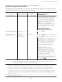
1
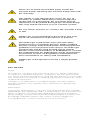
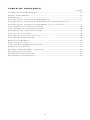
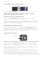
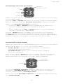
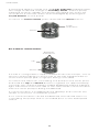
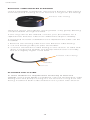
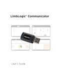
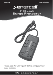
LimbLogic®
Patient
Instructions
LimbLogic features an electronically controlled
Vacuum Pump that uses air pressure and a sealing
sleeve to securely suspend your prosthesis.
The fob included with the system provides you
with wireless control and monitoring of the
vacuum level.
Please review these instructions thoroughly
and contact your prosthetist if you have any
questions.
1
There are no field-serviceable parts inside the
Vacuum Pump. Opening the Vacuum Pump will void
the warranty.
This pump is only designed to move air; use of
Vaseline® or similar lubricating creams inside the
socket will clog the pump. Do not allow foreign
substances to be pulled through the Vacuum Pump.
This may impair function of your vacuum system.
Do not allow acetone to contact the Vacuum Pump
or fob.
LimbLogic is not intended to be used as the only
means of attachment of prosthesis to patient.
All LimbLogic components have passed safety
testing for use as medical devices. Radio enabled
devices comply with United States and international
guidelines for low power transceivers. If LimbLogic
components will be used around safety critical
devices such as pacemakers or defibrillators, consult
the manufacturer for appropriate usage instructions.
Consult the section on Regulatory Information for
more information on safety and compliance.
LimbLogic is designed for use by a single patient
only.
FCC NOTICE
Note:
This device complies with part 15 of the FCC Rules. Operation
is subject to the following two conditions: (1) This device may
not cause harmful interference, and (2) this device must accept
any interference received, including interference that may cause
undesired operation.
Changes or modifications not approved by The Ohio Willow
Wood Company may void the user’s authority to operate this
equipment.
Remarque:
Le présent appareil est conforme aux CNR d’Industrie Canada
applicables aux appareils radio . L’exploitation est autorisée aux
deux conditions suivantes: (1) l’appareil ne doit pas produire
de brouillage, et (2) l’utilisateur de l’appareil doit accepter tout
brouillage radioélectrique subi, même si le brouillage est
susceptible d’en compromettre le fonctionnement.
2
TABLE OF CONTENTS
Page
Installing the Fob Battery.......................................................................... 4
Quick-Start Guide..........................................................................................5
Fob Guide.........................................................................................................5
Charging the Vacuum Pump Battery.................................................... 6
Charging the Vacuum Pump Battery Outside the U.S.....................7
Charging the Vacuum Pump Battery in a Vehicle.............................7
Turning On the Vacuum Pump..................................................................8
Turning Off the Vacuum Pump.................................................................8
Resetting the Vacuum Pump.....................................................................8
Turning On the Fob.......................................................................................8
Changing Vacuum Set Point..................................................................... 9
Changing Usage Mode................................................................................ 9
Bilateral Indicators.......................................................................................10
Detecting a Leak........................................................................................... 11
Vacuum Pump Battery Status.................................................................. 11
Exposure to Water........................................................................................ 11
Exhaust Tube Muffler Cleaning............................................................... 12
Flushing the System.................................................................................... 12
Troubleshooting Guide.............................................................................. 13
Regulatory Information............................................................................. 17
3
Overview
INSTALLING THE FOB BATTERY
The fob uses a commercially available CR2032 coin cell battery.
The battery that is shipped with the system must be installed prior
to using the fob.
The battery will normally have to be replaced every 3 months
depending upon how much the fob is used.
The fob case can be pried open using a small flat blade screwdriver, then snapped back together starting at the battery end
and working back toward the opposite end.
After the battery is replaced, the system does a quick
check by illuminating all the LED indicators. If all of the
LEDs do not illuminate, then either the battery or the
LEDs are not working, or the battery has been installed
upside-down.
4
Overview
QUICK-START GUIDE
1. Turn on the Vacuum Pump.
Press one time.
Pump will beep once.
Wait 10 seconds.
2. Turn on the fob.
Press and hold center button until the yellow
digits flash in a “chasing” pattern and then
display the current vacuum level.
The pump will operate until the preselected
vacuum level has been reached.
3. To enter Standby Mode:
Press for approximately 2 seconds.
The chasing pattern will be displayed,
then the white Standy Indicator will light.
To resume vacuum regulation:
Press for approximately 2 seconds.
The chasing pattern will be displayed
as the pump returns to Active Mode.
4. Turn off the Vacuum Pump.
Press one time.
Pump will beep twice.
FOB GUIDE
Vacuum Pump Battery Indicator
50-100%
30-50%
20-30%
< 20%
Bilateral Indicators
Current
Vacuum
Level
Standby
Indicator
(White)
Up
Enter
Leak
Indicator
(Red)
Down
5
Overview
CHARGING THE VACUUM PUMP BATTERY
The Vacuum Pump should be charged before it is used for the
first time, at the end of each day of use, and when the Battery
Indicator on the fob is red.
Vacuum Pump
Charger
To AC
outlet
AC Adapter
charging
port
charging plug
LLV-21011
2012
13.8 0V
Flashing:
Charged
PN-1988-H
ABN: 22582837497
solid:
Charging
Node LED
Adapter LED
(indicates that AC outlet is
providing power to Charger)
Node LED (indicates Charger function)
RED = fault
SOLID = charging
FLASHING = charged
1.
Insert the charging plug all the way into the charging port.
2.
Plug the Charger into a power outlet. The Adapter LED will
light. The battery indicator on the fob will flash alternately
between red and green. If the battery indicator does not
light, make sure you have inserted the charging plug all the
way into the port.
If the Node LED is red, reset the Charger by unplugging it
from the wall and plugging it back in.
While charging is in progress, the Node LED will be solid.
3.
When charging is complete, the Node LED will flash.
Disconnect the Charger from the Vacuum Pump and from
the power outlet.
When you are ready for the pump to begin regulating the
vacuum, either turn on the fob (refer to page 8) or press the
on/off button on the Vacuum Pump. The pump will operate
until the preselected vacuum level is reached.
Note: if the pump has just been unplugged from the Charger, it
will be in Standby Mode (refer to page 9). To resume vacuum
regulation, press the on/off button one time. To turn the pump
off, press the on/off button again.
Use ONLY a WillowWood Charger. Use of any other
charger may result in damage to the Vacuum Pump
or the charger or both.
With normal usage, the rechargeable battery should last for the
life of the product.
Do not use the Charger near water. The Charger is
not waterproof.
6
Overview
CHARGING THE VACUUM PUMP BATTERY OUTSIDE THE
UNITED STATES
If you have an international Charger, your Charger will come
with a collection of prong adapters that will allow you to use
your Charger in many countries.
Plugging a prong set into an outlet without the
Charger may expose you to dangerous voltages.
Always plug the prong set into the Charger before
plugging the Charger or the prong set into an outlet.
CHARGING THE VACUUM PUMP BATTERY IN A VEHICLE
To use a vehicle’s power to charge the Vacuum Pump, you must
purchase a Power Inverter rated at 75 Watts or less to convert
the vehicle’s 12V DC power to 120V AC. Examples of acceptable
Power Inverters include the Digital Concepts™ 75 Watt Portable
Power Inverter (available from general retailers) and the
Enercell™ 75 Watt Power Inverter (available from Radio Shack®;
item number 22-133).
1.
Plug the Power Inverter into the vehicle’s 12V DC socket.
2.
Connect the Charger to the Vacuum Pump.
3.
Plug the Charger’s AC adapter into the Power Inverter’s
three-pronged receptacle.
Do not operate the Charger above 41˚C (105˚F).
7
Overview
TURNING ON THE VACUUM PUMP
on/off button
Press the on/off button on the Vacuum Pump one time. The
Vacuum Pump will beep once.
Before turning on the fob as described below, wait 10
seconds for the pump to activate.
TURNING OFF THE VACUUM PUMP
Press the on/off button on the Vacuum Pump and hold for
1 second. The Vacuum Pump will beep twice.
Note: if the pump has just been unplugged from the Charger, it
will be in Standby Mode (refer to page 9). To resume vacuum
regulation, press the on/off button one time. To turn the pump
off, press the on/off button again.
RESETTING THE VACUUM PUMP
It is possible for a large static discharge to interrupt normal
operation. Should this occur, press the on/off button on the
Vacuum Pump and hold for at least 12 seconds until the unit
beeps. Resetting the pump may also be required when the fob
displays certain error codes (refer to page 16).
TURNING ON THE FOB
Current
vacuum level
Enter
Make sure the pump is on has been on for at least 10 seconds.
Press and hold the Enter (center) button for approximately
2 seconds until the yellow digits flash in a circular “chasing”
pattern. The chasing pattern indicates the fob is attempting to
communicate with the pump.
When the fob connects to the pump, the current vacuum level
will be displayed in the center. A connected fob will shut off
after one minute of non-use.
If the pump is off or fails to connect to the fob, the chasing
pattern will end after 6 seconds, and all fob LEDs will turn off.
For bilateral systems, if the fob cannot establish communications
with the first pump, the fob will attempt to connect to the
second pump, using the same steps as above. If communication
cannot be established with either pump, the fob will shut down.
8
Overview
CHANGING VACUUM SET POINT
Current
vacuum level
Up
Enter
Down
Make sure the fob is on and displaying the current vacuum level
in the yellow digits.
Press the Up or Down button for 1 second until the yellow digits
flash to indicate that the Vacuum Set Point is being changed.
Adjust the Vacuum Set Point as follows:
• Press the Up or Down button repeatedly to adjust the
Vacuum Set Point by one number at a time.
or
• Press and hold the Up or Down button until the desired
Vacuum Set Point is displayed.
Press the Enter button to apply the changes. The “chasing”
pattern will be displayed while the setting is being applied. If
the Enter button is not pressed, the settings will not be applied,
and the fob will shut off due to inactivity in 60 seconds.
CHANGING USAGE MODE
Make sure the fob is on and displaying the current vacuum level.
When the pump is on, it has two usage modes:
Active Mode: Vacuum Pump activates as needed to
maintain the vacuum level
Standby Mode: allows you to temporarily suspend
vacuum regulation
Press and hold the Enter button to toggle the vacuum pump
from one mode to the other. The “chasing” pattern will be
displayed while the change in mode is being applied.
Standby
Indicator
Enter
The white Standby indicator will illuminate when the Vacuum
Pump is in Standby Mode. The fob will continue to display
vacuum levels while in Standby Mode.
When the white Standby Indicator is not illuminated, the pump
is in Active Mode.
9
Overview
If the pump detects a leak, the red Leak Indicator will illuminate,
the usage mode will change to Standby Mode, and the pump
will beep 10 times rapidly. The pump will repeat this every 30
seconds for 6 minutes unless acknowledged by pressing the
on/off button on the pump.
To return to Active Mode, press and hold the Enter button.
Leak
Indicator
Enter
BILATERAL INDICATORS
Bilateral
Indicators
Up
Down
If a fob is configured to support bilateral Vacuum Pumps, one of
the two white indicators at the top of the fob will illuminate to
show which pump (left or right) is being controlled.
To switch the fob from controlling one pump to the other, press
and hold the Up and Down buttons together for approximately
1 second. The “chasing” pattern will be displayed, and the indicator
light will switch from one side to the other while communication
with the other pump is being established.
If communication is established, the displays and controls are
similar to those for a unilateral system.
If no communication can be established, the fob will return to
controlling the pump that it controlled prior to the attempted
switch.
10
Overview
DETECTING A LEAK
Leak
Indicator
If the Vacuum Pump detects a leak, the red Leak Indicator
will illuminate, and the system will enter Standby Mode.
At this time, the pump will make 10 short beeps. This will repeat
every 30 seconds for 6 minutes unless acknowledged by
pressing the on/off button on the pump.
If the Leak Indicator appears when you initially don your
prosthesis, restart the pump.
If the Leak Indicator appears frequently while you are
walking, contact your prosthetist.
To resume automatic vacuum regulation after a leak has been
detected, press the on/off button on the Vacuum Pump one
time or press the Enter button on the fob.
VACUUM PUMP BATTERY STATUS
Vacuum Pump
Battery Indicator
The Battery Indicator flashes alternatively between red and green
when the Vacuum Pump battery is charging.
The level of charge is indicated as follows:
• Solid green: Vacuum Pump battery is between 50% and
100% charged.
• Flashing green: Vacuum Pump battery is between 30% and
50% charged.
• Solid red: Vacuum Pump battery is between 20% and 30%
charged.
• Flashing red: Vacuum Pump battery is less than 20%
charged. The battery should be charged when possible. The
pump will shut down when the battery level reaches 0%.
• At 10% the pump will start to beep 3 times every 30
seconds. This will repeat for 6 minutes unless acknowledged
by pressing the on/off button on the pump.
EXPOSURE TO WATER
The Vacuum Pump is waterproof in fresh water up to a depth of
10 feet or 3 meters for up to 12 hours. The Vacuum Pump should
not be submersed in salt water or any other corrosive liquids. Be
sure to dry off the Vacuum Pump if it is exposed to rain or other
moisture.
The fob and Charger should not be exposed to water or other
liquids.
11
Overview
EXHAUST TUBE MUFFLER CLEANING
Using a flat blade screwdriver, remove the Exhaust Tube Fitting
from the pump housing. Do not lose the o-ring from the fitting.
Exhaust Tube Fitting
Clear the clog in the tube by running water or by gently blowing
compressed air through the tube.
If the clog cannot be cleared, contact your prosthetist for a
replacement Exhaust Tube from WillowWood (LLV-21080).
If the pump must be used before the replacement tube can be
installed:
1. Remove the existing tube from the Exhaust Tube Fitting.
2. Cut the existing tube just past the Muffler.
3. Connect the Exhaust Tube Fitting to the section of tube that
does not have the Muffler. The pump will function normally,
but at a slightly higher noise level.
Exhaust Tube Fitting
Muffler
Cut here
FLUSHING THE SYSTEM
In some situations it may become necessary to flush the
system. Using a flat blade screwdriver, remove the Exhaust Tube
Fitting from the pump housing. Do not lose the o-ring from the
fitting. Install the drain tube and flush the system with alcohol.
12
Overview
TROUBLESHOOTING GUIDE
If you are still experiencing a problem after consulting this
guide, contact your prosthetist.
Problem
Action
The pump does
not beep when
the on/off button
is pressed and
the Charger is
not connected to
the pump.
• The pump’s internal battery may not
be charged. Charge the pump with the
Charger for at least 30 minutes and try
again.
• The on/off button could be damaged.
Verify that the rubber boot is intact
and hasn’t been torn from impact.
Contact your prosthetist if the switch
needs to be replaced.
• The pump may have been exposed to
a large static charge. Press and hold
the on/off button on the pump until
you hear a beep (approximately 12
seconds).
Pressing the
pump button
does not start
the pump.
• The pump’s internal battery may not
be charged. Charge the pump with the
Charger for at least 30 minutes and try
again.
• The pump may have been exposed to
a large static charge. Press and hold
the on/off button on the pump until
you hear a beep (approximately 12
seconds).
• The pump may be partially stalled.
Refer to the “Pump Stall” error code
information on page 16.
Pump battery
does not
maintain charge
for a full day.
• Ensure that the system is properly
sealed.
• Ensure that the battery has been
charged for at least 4 hours.
• The pump may have been exposed to
a large static charge. Press and hold
the on/off button on the pump until
you hear a beep (approximately 12
seconds).
• Ensure that your socket does not leak
excessively.
The pump makes
a “zip zip zip”
sound as it
controls the
vacuum.
Contact your prosthetist.
Pressing the
center button of
the fob does not
cause the yellow
LEDs to light in a
“chasing”
pattern.
The battery is likely dead and must be
replaced per the instructions on page 4.
Vacuum Level
display on fob
does not respond
to changes in
vacuum level in
your socket.
Contact your prosthetist.
continued on next page
13
Overview
Problem
Action
The fob does not
communicate
with the pump.
The “chasing”
pattern of LEDs
ends after 6
seconds, and the
LEDs turn off.
• Wait one minute for the fob screen to
turn off. Make sure the pump is on by
pressing the on/off button and verify
that the pump beeps once. Listen for
about 30 seconds to make sure that the
pump doesn’t quickly beep twice and
turn off, which indicates a battery
problem. Press the fob center button
again.
• The fob may be too close or too far
from the pump. Place the fob about
2 feet away from the pump, and press
the fob center button again.
• The pump’s internal battery may not
be charged. Charge the pump with the
Charger for at least 30 minutes and try
again.
• The pump may have been exposed to a
large static charge. Press and hold the
on/off button on the pump until you
hear a beep (approximately 12
seconds).
• Do you have the correct fob-pump
combination? The fob and pump are
electronically matched during the production process. Ask your prosthetist
to contact WillowWood with the serial
number of the fob and serial number
of the pump to verify that the set is
matched.
The Adapter
LED on the
Charger does
not illuminate
when plugged
into the wall.
• The AC electricity to the wall outlet
may not be turned on. Try plugging the
Charger into a different non-switched
wall outlet or in another room.
• The configurable prong may not be
seated properly in the back of the
Charger’s AC Adapter. Unplug the
Charger from the AC outlet. Remove
the Charger’s prong using the sliding
latch on the back of the adapter. Verify
that the metal contacts are springy
and are not completely flat against the
adapter. Re-install the plug prongs.
• If the problem persists, contact your
prosthetist.
The Node LED
on the Charger
does not light
or blink when
the Charger is
plugged into
vacuum pump
and AC outlet.
Contact your prosthetist.
The Node LED
is red.
Reset the Charger by unplugging it from
the wall and plugging it back in.
continued on next page
14
Overview
Problem
Action
The pump runs
repeatedly.
Using a flat blade screwdriver, remove the
Exhaust Tube Fitting from the pump
housing. Do not lose the o-ring from the
fitting. Install the drain tube and flush the
system with alcohol.
The pump beeps
but does not run.
The Muffler on the Exhaust Tube may be
clogged. Clean the Muffler as described on
page 12.
15
Overview
Error Codes
If the vacuum pump’s controller detects an error from which it
cannot recover, the fob display will alternate between the letters
“Er” and a two-digit error code. Refer to the chart below for the
type of error indicated by each code and the corresponding
action.
Problem
Description
Cause
Action
01
Pump stall
Possibly
debris or
lubricant
stuck in
pump
Reset the pump
by pressing and
holding the pump’s
on/off button for
approximately 12
seconds until you
hear a beep, then
flush the system
with alcohol (refer
to Flushing the
System on page
12).
02
Temp out of
range
Pump temperature less
than -20˚ C
or greater
than 70˚ C
Allow pump
temperature to
return to operating
range, then reset
the pump by
pressing and
holding the pump’s
on/off button for
approximately 12
seconds until you
hear a beep.
03
Motion fail
Motion
sensor failure
Contact your
prosthetist.
04
ADC fail
Analog
Digital
Converter
failure
Contact your
prosthetist.
05
Memory
Memory
failure
Reset the pump
by pressing and
holding the pump’s
on/off button for
approximately 12
seconds until you
hear a beep.
If problem persists,
contact your
prosthetist.
06
Radio
BLE Radio
failure
Contact your
prosthetist.
07
Vacuum
Vacuum
Sensor failure
Contact your
prosthetist.
08
Battery
Battery
monitoring
circuit failure
Contact your
prosthetist.
16
Technical Information
REGULATORY INFORMATION
Return this product to the factory for proper dispoal.
LimbLogic Fob
This product contains a user replaceable lithium battery.
Replace only with user replaceable CR2032 batteries.
Discard of discharged batteries in accordance with local
regulations. Observe polarity markings on the battery
and the fob housing when replacing the battery.
This product complies with: EN 60601-1-2:2007,
IEC 60601-1-2 ED. 3.0, and IEC 60601-1:2005
+CORR.1(2006) + CORR. 2 (2007).
IEC 60601-1 Classifications:
Internally powered
Degree of protection against electrical shock –
Type BF Applied Part
In addition to the above compliances, this device
complies with EN55022:1998/A1:2000/A2:2003 Class
B ITE emissions requirements and all requirements
for Low Interference Potential Devices (LIPD) and
compliance with the requirements for a General User
Licence (GUL).
LimbLogic Vacuum Pump
This product contains a rechargeable Lithium Ion
Battery. Use ONLY a Willow Wood charger. Use of other
chargers may result in harm to the device, the user, or
both and void the warranty.
Blocking or plugging the exhaust port of the vacuum
control assembly will prevent proper operation of the
vacuum pump.
The LimbLogic Vacuum Pump is intended for use on a
single patient. Use of the system with multiple patients
could lead to cross contamination between patients.
The LimbLogic vacuum system has been designed
for and clinically tested as a suspension aid. It has not
been clinically tested for wound healing or other uses.
WillowWood does not currently support the use of the
LimbLogic for uses other than suspension.
Use only the bolts supplied by WillowWood. All testing
for the LimbLogic vacuum system has been tested with
the bolts included with the system. Use of other bolts
could result in mechanical failure.
This product complies with: EN 60601-1-2:2007, IEC
60601-1-2 ED. 3.0, IEC 60601-1:2005 +CORR.1(2006)
+ CORR. 2 (2007), CEI/IEC 60529:1989+A1:1999
rating IPX8 (3 meters for 8 hours in fresh water), and
ISO 10328:2005.
IEC 60601-1 Classifications:
Internally powered/Powered from Class II Power Supply
Degree of protection against electrical shock –
Type BF Applied Part
This product complies with the requirements of ISO 10328.
In addition to the above compliances, this device complies
with EN55022:1998/A1:2000/A2:2003 Class B ITE emissions
requirements and all requirements for Low Interference
Potential Devices (LIPD) and compliance with the requirements for a General User Licence (GUL).
17
Technical Information
LimbLogic Battery Charger
This product is designed to work with WillowWood
products specifically designed for its use. Use
WillowWood charger part number LLV-21011. Use with
other products may result in harm to the device, the
user, or both and void the warranty. Refer to product
manuals to verify compatibility with this charger before attempting to use this charger with the product.
Electrical Ratings:
Rated input: 100 – 240 Vac, 0.6 A, 47 – 63 Hz
Rated output: 13.8 Vdc, 2.6 A
This product complies with: EN 60601-1-2:2007,
IEC 60601-1-2 ED. 3.0, and IEC 60601-1:2005
+CORR.1(2006) + CORR. 2 (2007) and meets the
“ICNIRP GUIDELINES FOR LIMITING EXPOSURE TO
TIME-VARYING ELECTRIC AND MAGNETIC FIELDS
(1 HZ – 100 kHZ):2010”.
FCC AND IC COMPLIANCE INFORMATION
(FOR THE FOB AND THE VACUUM PUMP)
Note:
This equipment contains:
FCC ID XDULE40-S2
IC: 8456A-LE4S2)
Contient le module d’émission
IC: 8456A-LE4S2
FOR THE CHARGER
This equipment contains:
FCC ID U3V-LLV21011
This device complies with Part 15 of the FCC Rules. Operation is
subject to the following two conditions:
1. This device may not cause harmful interference, and
2. This device must accept any interference received, including
interference that may cause undesired operation.
Radio Frequency Interference Statement
This is a Class B product. In a domestic environment, this product may cause radio interference in which case the user may be
required to take adequate measures.
Note:
This equipment has been tested and found to comply with the
limits for a Class B digital device, pursuant to part 15 of the FCC
Rules. These limits are designed to provide reasonable protection against harmful interference in a residential installation.
This equipment generates, uses and can radiate radio frequency
energy and, if not installed and used in accordance with the instructions, may cause harmful interference to radio communications. However, there is no guarantee that interference will not
occur in a particular installation. If this equipment does cause
harmful interference to radio or television reception, which can
be determined by turning the equipment off and on, the user is
encouraged to try to correct the interference by one or more of
the following measures:
—Reorient or relocate the receiving antenna.
—Increase the separation between the equipment and receiver.
—Connect the equipment into an outlet on a circuit different
from that to which the receiver is connected.
—Consult the dealer or an experienced radio/ TV technician
for help.
18
Technical Information
This digital apparatus does not exceed the Class B limits for radio
noise emissions from digital apparatus set out in the Radio Interference Regulations of the Canadian Department of Communications.
REMARQUE:
Cet équipement a été testé et déclaré conforme aux les règles de
ICES-001. Ces limites ont pour objectif de fournir une protection
raisonnable contre les interférences nuisibles dans une installation
résidentielle. Cet équipement génère, utilise et rayonne de l’énergie
de fréquence radio et peut nuire aux communications radio
s’il n’est pas installé et utilisé en accord avec le mode d’emploi.
Cependant, il n’est pas garanti que des interférences surviennent dans une installation particulière. Si l’équipement cause
des interférences nuisibles à la réception radio ou télévision, qui
peuvent être localisées en allumant ou en éteignant l’équipement,
l’utilisateur est encouragé à corriger les interférences en employant une ou plusieurs des mesures suivantes:
—Réorienter ou déplacer l’antenne de réception.
—Séparer davantage l’équipement et le récepteur.
—Connecter l’équipement à une prise de courant située sur un
circuit différent de celui du récepteur.
—Demandez assistance à un revendeur ou un technicien expérimenté dans le domaine radio/TV.
ELECTROMAGNETIC COMPATIBILITY
Medical electrical equipment needs special precautions regarding
electromagnetic compatibility (EMC) and needs to be installed and
put into service according to the EMC information provided in this
user manual. Portable and mobile radio frequency (RF) communications equipment can affect medical electrical equipment.
Guidance and Manufacturer’s Declaration Electromagnetic Emissions
LimbLogic is intended for use in the electromagnetic environments
specified below. The customer or the user of the LimbLogic should
assure it is used in such an environment.
Emissions test
Compliance
Electromagnetic
environment - guidance
RF emissions
CISPR 11
Group 2
LimbLogic must emit
electromagnetic energy in
order to perform its intended function. Nearby
electronic equipment may
be affected.
RF emissions
CISPR 11
Class B
Harmonic emissions
IEC 61000-3-2
Class A
Voltage fluctuations/
flicker emissions
IEC 61000-3-3
Complies
LimbLogic is suitable
for use in all establishments, including domestic
establishments and those
directly connected to the
public low-voltage power
supply network that supplies buildings used for
domestic purposes.
Emissions from this device comply with the recommendations
of the ICNIRP’s “Guidelines for Limiting Exposure to Time-Varying Electric and Magnetic Fields (1 Hz - 100 kHz). Health Physics
99(6):818-836; 2010.
19
Technical Information
Guidance and Manufacturer’s Declaration Electromagnetic Immunity
LimbLogic is intended for use in the electromagnetic environments
specified below. The customer or the user of the LimbLogic should
assure it is used in such an environment.
Immunity
test
IEC 60601
test level
Compliance
level
Electromagnetic
environment guidance
Electrostatic
discharge
(ESD)
IEC 61000-4-2
± 6 kV
contact
± 6 kV
contact
± 8 kV air
± 8 kV Air
Floors should be
wood, concrete, or
ceramic tile. If floors
are covered with
synthetic material,
the relative humidity
should be at least
30%.
Electrical fast
transient/
burst
IEC 61000-4-4
± 2 kV for
power
supply lines
± 2 kV on
power
supply lines
± 1 kV on
input/
output lines
± 1 kV on
Input/
output lines
Surge
IEC 61000-4-5
± 1 kV
differential
mode
± 1 kV
differential
mode
± 2 kV
common
mode
± 2 kV
common
mode
< 5% UT
< 5 % UT
(>95 % dip
in UT) for
0,5 cycle
(>95 % dip
in UT) for
0,5 cycle
40% UT
40% UT
Voltage dips,
short interruptions and voltage variations
on power
supply input
lines
IEC 61000-4-11
Power
frequency
(60% dip in (60% dip
UT) for
in UT) for
5 cycles
5 cycles
70% UT
70% UT
(30% dip
in UT) for
25 cycles
(30% dip
in UT for
25 cycles
< 5% UT
< 5% UT
(>95 % dip
in UT) for
5 sec
(>95 % dip
in UT) for
5 sec
3 A/m
3 A/m
(50/60 Hz)
magnetic field
IEC 61000-4-8
Mains power quality
should be that of a
typical commercial
or hospital
environment.
Mains power quality
should be that of a
typical commercial
or hospital
environment.
Mains power quality
should be that of a
typical commercial
or hospital
environment. If
the user of the
LimbLogic requires
continued
operation during
mains interruptions,
it is recommended
that the LimbLogic
be powered from
an uninterruptible
power supply or a
battery.
Power frequency
magnetic fields
should be at levels
characteristic of
a typical location
in a typical commercial or hospital
environment.
NOTE UT is the a.c. mains voltage prior to application of the test level.
20
Technical Information
Guidance and Manufacturer's Declaration Electromagnetic Immunity
LimbLogic is intended for use in the electromagnetic environments
specified below. The customer or the user of the LimbLogic should
assure it is used in such an environment.
Immunity
test
IEC 60601 Compliance Electromagnetic
environment test level
Level
guidance
Portable and mobile RF
communications equipment should be used
no closer to any part of
the LimbLogic, including
cables, than the recommended separation
distance calculated from
the equation applicable
to the frequency of the
transmitter.
Recommended
separation distance
Conducted RF 3 Vms
IEC 61000-4-6 150 kHz to
80 MHz
3V
3 V/m
Radiated RF
IEC 61000-4-3 80 MHz to
2.5 GHz
3 V/m
80 MHz to 800 MHz
800 MHz to 2.5 GHz
where P is the maximum
output power rating of the
transmitter in watts (W)
according to the transmitter manufacturer and
d is the recommended
separation distance in
meters (m).
Field strengths from
fixed RF transmitters, as
determined by an electromagnetic site survey,a
should be less than the
compliance level in each
frequency range.b
Interference may occur in
the vicinity of equipment
marked with the following
symbol:
NOTE 1 At 80 MHz and 800 MHz, the higher frequency range applies.
NOTE 2 These guidelines may not apply in all situations. Electromagnetic propagation is affected by absorption and reflection
from structures, objects and people.
a Field strengths from fixed transmitters, such as base stations for
radio (cellular/cordless) telephones and land mobile radios, amateur
radio, AM and FM radio broadcast and TV broadcast cannot be
predicted theoretically with accuracy. To assess the electromagnetic
environment due to fixed RF transmitters, an electromagnetic site
survey should be considered. If the measured field strength in the
location in which the LimbLogic is used exceeds the applicable RF
compliance level above, the LimbLogic should be observed to verify
normal operation. If abnormal performance is observed, additional
measures may be necessary, such as reorienting or relocating the
LimbLogic.
b Over the frequency range 150 kHz to 80 MHz, field strengths should
be less than 3 V/m.
21
Technical Information
Recommended separation distances between portable and
mobile RF communications equipment and the LimbLogic
LimbLogic is intended for use in an electromagnetic environment
in which radiated RF disturbances are controlled. The customer
or the user of LimbLogic can help prevent electromagnetic
interference by maintaining a minimum distance between portable
and mobile RF communications equipment (transmitters) and
the LimbLogic as recommended below, according to the maximum
output power of the communications equipment.
Separation distance according
to frequency of transmitter m
Rated maximum
output power
of transmitter W
150 kHz to
80 MHz
80 MHz to
800 MHz
800 MHz to
2.5 GHz
0.01
0.12
0.12
0.23
0.1
0.38
0.38
0.73
1
1.2
1.2
2.3
10
3.8
3.8
7.3
100
12
12
23
For transmitters rated at a maximum output power not listed
above, the recommended separation distance d in meters
(m) can be estimated using the equation applicable to the
frequency of the transmitter, where P is the maximum output
power rating of the transmitter in watts (W) according to the
transmitter manufacturer.
NOTE 1 At 80 MHz and 800 MHz, the separation distance
for the higher frequency range applies.
NOTE 2 These guidelines may not apply in all situations.
Electromagnetic propagation is affected by
absorption and reflection from structures, objects
and people.
22
Technical Information
USER PROFILE
Prosthetist user
LimbLogic is intended to be used for assembly of prosthetic
devices by a certified prosthetist or prosthetic technician.
Patient user
LimbLogic is intended for use by patients meeting the following
conditions.
– Age: Any. Determined by clinician’s evaluation of patient
competence and health.
– Weight: (Body weight plus any loads normally or routinely
carried cannot exceed these weight limits.)
<350 lb (160 kg) for U.S. Activity K Level 2 or 3
<300 lb (136 kg) for U.S. Activity K Level 4
– Health: Activity Level K2-K4
– Nationality: Any
– Mentally competent to operate system as judged by
prosthetist.
PERFORMANCE CHARACTERISTICS
Capabilities:
– 2 year warranted service life
– Vacuum setting up to 68 kPa. For ease of use, this range has
been divided into twenty even steps between 1 and 20.
– Indoor & Outdoor usage
– The LimbLogic Controller (pump) is waterproof in fresh water
to a depth of 3 meters (10 feet) for up to 12 hours at a time.
– Operating temperature range:
0 °C to +50 °C
– Transportation and storage temperature range: -20 °C to +50 °C
– Humidity range:
10 % to 90 % RH, non condensing
– Transportation and storage humidity range:
0 % to 100 % RH, non condensing
– Altitude range:
0 to 5500 feet
– Transportation and storage altitude range:
-500 to 20,000 feet
Restrictions:
– LimbLogic must not be used in salt water or any other corrosive
environment.
– At temperatures below freezing, condensation will form and
freeze in the pump preventing further operation until warmed.
– The hand-held fob, communicator, and charger should not be
exposed to water.
– Frequency of use: Daily for 16 hours / day or as needed.
PHYSICAL MEASUREMENTS
Module
Dimensions (mm)
Fob with Battery
38L x 31W x 8H
17
Pump
36H x 74DIA
231
Charger Wall
Transformer
86L x 56W x 37H
261
23
Weight (gms)
The Ohio Willow Wood Company
15441 Scioto Darby Road
Mt. Sterling, OH 43143
phone 740.869.3377 / 800.848.4930
fax 740.869.4374 www.willowwoodco.com
Ohio Willow Wood Company B.V
Keizersgracht 62/64
1015 CS Amsterdam
The Netherlands
PN-2014-N 1 MAY 2013
Covered by one or more Patents: US 8,242,879;
24
8,016,892; 7,947,085; 7,914,586
Other Patents Pending