1
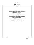
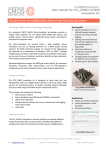
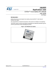
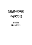
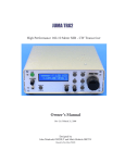
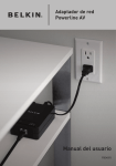
UM1806 User manual EFL700A39 evaluation board kits and design-in board user guide Introduction This note describes the operation and the instruction for using the two boards developed for training and supporting the design of the solid state thin film battery EnFilm™ EFL700A39. The evaluation kit (order number: EFL700EVALKIT) allows to discover the operation of the EFL700A39 and to monitor the voltage and the dynamic charge / discharge current in real use-case condition. The power management board (order number: EFL700PMB) is rather a design-in board including all the necessary power management circuit around the EFL700A39 and can be directly connected and used in the application for a fast evaluation. Figure 1. EFL700EVALKIT August 2015 Figure 2. EFL700PMB DocID026737 Rev 2 1/16 www.st.com EFL700 power management board (EFL700PMB) UM1806 1 EFL700 power management board (EFL700PMB) 1.1 Pictures of the power management board (PMB) Figure 3. EFL700PMB board top side 1.2 Figure 4. EFL700PMB board bottom side Block diagram of the power management board (PMB) Figure 5. EFL700PMB synoptic $GGH[WHUQDO MXPSHUVZKHQ30% ERDUGLVXVHGZLWKRXWWKH/%ERDUG , 7R 3KRWRYROWDLF SDQHO 9PLQ $ 7R86%SRUWIRU ()/$IDVW FKDUJLQJ ,¶ , ,¶ 6: 39LQSXW 86% SRZHUVXSSO\ LQSXW 3RZHU PDQDJHPHQW DQG GHHSGLVFKDUJH SURWHFWLRQ ()/$ 32:(50$1$*(0(17%2$5' 2/16 287 DocID026737 Rev 2 %XIIHU FDS 7RUDGLRV\VWHP RUZKLFKHYHU PLFURFRQWUROHU V\VWHP UM1806 EFL700 evaluation kit (EFL700EVALKIT) 2 EFL700 evaluation kit (EFL700EVALKIT) 2.1 Picture of the complete evaluation kit with the PMB connected to the load board (LB) Figure 6. EFL700EVALKIT boards connected DocID026737 Rev 2 3/16 16 EFL700 evaluation kit (EFL700EVALKIT) 2.2 UM1806 Block diagram of the complete evaluation kit with the PMB connected to the load board (LB) Figure 7. EFL700EVALKIT synoptic /2$'%2$5' 3% 3% 9 9ROWPHWHU $PPHWHU 7R9SRZHU VXSSO\ '&SRZHU VXSSO\ LQSXW 3% 3% &XUUHQW VHQVLWLYLW\ 25 7R86%SRUW 7R3KRWRYROWDLF SDQHO 9PLQ$ 7R86%SRUWIRU ()/$IDVW FKDUJLQJ 86%SRZHU VXSSO\LQSXW 3XOVHG ORDG FRQWURO /RDG , ,¶ , ,¶ 287 , ,¶ , ,¶ 287 6: 39LQSXW 86% SRZHUVXSSO\ LQSXW 3RZHU PDQDJHPHQW DQG GHHSGLVFKDUJH SURWHFWLRQ ()/$ 32:(50$1$*(0(17%2$5' 4/16 6: DocID026737 Rev 2 %XIIHU FDS 7RUDGLRV\VWHP RUZKLFKHYHU PLFURFRQWUROHU V\VWHP UM1806 3 General description and features General description and features The EFL700A39 EnFilm ™ battery brings many benefits compared to conventional battery: • Low thickness • Low self-discharge • Extremely long calendar and cycle life time • High safety with no risk of burning or explosion EFL700PMB and EFL700EVALKIT kits were developed to help designers to evaluate the charge and discharge performances of the EFL700A39 with a proper setup of power management. The EFL700PMB includes one PCB: The power management board (PMB), same size as the EFL700A39 battery mounted on the top side. The EFL700EVALKIT includes two PCB: The power management board (PMB) and the additional load board (LB). The power management board (PMB): • Manages the charge and the voltage regulation of the EFL700A39 • Protects battery against deep discharge • Supports the recharge through an external energy harvesting • Includes buffer capacitors to sustain high pulsed discharge current. Buffer capacitors can be disconnected with the switch SW1 The PMB can be used in association with USB port, photovoltaic panel or any kind of harvester with its own power management. The PMB can be connected to any kind of load with its own power management circuit. Whatever the harvester and load system are, the PMB allows a safe and efficient use of the EFL700A39 micro-battery. The load board (LB): • • Includes an analog ammeter and a digital voltmeter allowing the user to monitor: – The current delivered by the source by pressing PB1. – The current going through the EFL700A39 battery by pressing PB2. – The battery voltage Includes a pulsed load emulator with the possibility to adjust the pulsed load cyclic ratio. Its features are: – Enable / disable function by toggling the switch SW3. – Default pulsed load current set to 5 mA during a pulse time of 100 ms every 10 s. – Tunable pulse duration from 1 ms up to 100 ms through RA1 rheostat. – Tunable pulse repetition time from 1 s up to 10 s through RA2 rheostat. The LB can be powered via 2 mm banana connectors or a micro-USB plug. DocID026737 Rev 2 5/16 16 EFL700EVALKIT in details 4 UM1806 EFL700EVALKIT in details Figure 8. Description of the PMB and LB boards /%ERDUG $QDORJ$PPHWHU 'LJLWDO9ROWPHWHU &RQQHFW9H[WHUQDOSRZHU VXSSO\WRWKHVH PPEDQDQDSOXJV 3%SXVKEXWWRQWRPRQLWRU WKH39VXSSO\FXUUHQW 56URWDU\VZLWFKWRVHOHFW WKHDPPHWHUVHQVLWLYLW\ &RQQHFW86%FDEOHWRWKLV PLFUR86%SOXJLI9H[WHUQDO SRZHUVXSSO\LVQRWDYDLODEOH 3%SXVKEXWWRQWRPRQLWRU WKH()/$FXUUHQW 5$DQG5$UKHRVWDWVWR DGMXVWSXOVHGORDGFXUUHQW HPXODWRUVZLWFKLQJWLPH 6:VZLWFKWRDFWLYDWH SXOVHGORDGFXUUHQWHPXODWLRQ &RQQHFWD39SDQHORU DQ\RWKHU(+V\VWHPKHUH 39DQG39 SLQV &RQQHFWWKHV\VWHP/2$' KHUH287DQG287SLQV &RQQHFWDQ86%FDEOHWRWKLV PLFUR86%SOXJIRUD ()/$IDVWFKDUJLQJ 7KH67(Q)LOP()/$ VROLGVWDWHWKLQILOPEDWWHU\ 30%ERDUG 6/16 DocID026737 Rev 2 UM1806 5 Using the complete evaluation kit Using the complete evaluation kit The use of the EFL700EVALKIT discovery kit is recommended to get familiar with the PMB board operation and thus with the EFL700A39 electrical management characteristics. The complete discovery kit gives the possibility to monitor the EFL700A39 charging and discharging currents as if the EFL700A39 battery was used in a real case application with high pulse current load. It also helps to monitor the charging current delivered by an external charger like an energy harvesting device or an USB port. First connect +5 V power supply on LB board via 2 mm banana plugs or USB connector. Toggle the SW3 switch to the left position in order to switch “OFF” the pulsed load emulator operation. Then, connect an external PV panel or any other energy harvesting device having an output voltage above 5 V to the left side connector of the PMB board as shown in Figure 8 (PV+ and PV- pins). In order to monitor the current delivered by the PV through the analog ammeter, press the PB1 push button. The ammeter sensitivity can be adjusted by selecting the correct position of the RS rotary switch (depending on the PV current capability): – Position 1: “10” marking on the ammeter means 10 mA current is flowing. – Position 2: “10” marking on the ammeter means 1 mA current is flowing. – Position 3: “10” marking on the ammeter means 100 μA current is flowing. Pressing the PB2 push button will show through the ammeter the current that goes in or out of the EFL700A39 micro-battery. When turning “ON” both SW1 switches on the PMB board, the user connects 12 SMD buffer capacitors mounted on the PMB board to the output node. Buffer capacitors work in parallel with the EFL700A39 micro-battery and are dedicated for high current pulse applications. As shown in the Figure 9, SW1 is a two-way switch. Turning "ON" the way #1 connects 4 of the 12 buffer capacitors. Turning "ON" the way #2 connects 8 of the 12 buffer capacitors. Each of the 12 buffer capacitor is a 220 µF 1206 HiCap MLCC capacitor resulting actually in a typical 800 µF capacitance value under 4 V bias when all buffer cap are connected. The digital voltmeter indicates the charging voltage of either both EFL700A39 and buffer capacitor when SW1 switch is “ON” or EFL700A39 alone when SW1 switch is “OFF”. This digital voltmeter shall indicate +4.2 V when the EFL700A39 is fully charged. By turning “ON” the SW3 switch (right position), a current burst operation mode is emulated (default settings: 5 mA / 100 ms every 10 s). In order to see the behavior of the PMB board and particularly the EFL700A39 and buffer cap behavior press PB1 or PB2 (never press both at the same time). This will show how the charger and PMB work together. If the charge source does not provide enough current, the PMB board will supply burst current until the EFL700A39 voltage gets down to its security range. Indeed, when the battery voltage falls below 3.2 V the power management IC embedded on the PMB board will disconnect the EFL700A39 in order to prevent it from deep discharge. The adjustment of the pulsed load duty cycle can be performed with RA1 and RA2 rheostats. RA1 controls the pulse duration whereas RA2 controls the pulse repetition time. A probe scope can be connected between TP3 and TP4 test points to tune the switching time of the pulse load. If for any reason there is a need to fast charge the EFL700A39 and buffer capacitors then users can connect the PMB board micro USB plug to an external USB port. DocID026737 Rev 2 7/16 16 Using the PMB board separately 6 UM1806 Using the PMB board separately The PMB board can be used separately for your own application. It can be used to supply a real IoT (Internet of Things) application case with a micro-controller and radio circuit. For this it will be necessary to jump strap the I1 to I1’ pins and I2 to I2’ pins as shown below in Figure 9. Figure 9. Description of the PMB board ,I30%ERDUGLVXVHGVHSDUDWHO\ WKHQ-XPS6WUDS ,WR,¶DQG,WR,¶ &RQQHFWD39SDQHORU DQ\RWKHU(+V\VWHPKHUH 39DQG39 SLQV &RQQHFWWKHV\VWHP/2$' KHUH287DQG287SLQV 6:VZLWFKWRFRQQHFWEXIIHU FDSDFLWRUVRQ287QRGH :D\ 21FRQQHFWV [) :D\ 21 FRQQHFWV [) %RWK 21 FRQQHFWV [) &RQQHFWDQ86%FDEOHWRWKLV PLFUR86%SOXJIRUD ()/$IDVWFKDUJLQJ The PMB board characteristics are the following at 25°C: 8/16 • 4.2 V output voltage limitation during the charge of the battery • Deep discharge battery protection when output voltage gets down to 3.2 V • USB fast recharge DocID026737 Rev 2 UM1806 Electrical schematics 7 Electrical schematics 7.1 Power management board Figure 10. PMB electrical schematic 7.2 Load board Figure 11. LB electrical schematic DocID026737 Rev 2 9/16 16 Bill of materials 8 UM1806 Bill of materials Table 1. BOM of the power management board (PMB) Reference Designation BT EnFilm™ - rechargeable solid state lithium thin film battery C1 Ceramic capacitor C2-C13 Ceramic buffer capacitors Supplier Ref. parts Value STMicroelectronics EFL700A39 700µA.h / 3.9 V AVX 06033D105KAT2A 1µF MURATA GRM31CR60J227M 220µF TE Connectivity 1981584-1 CN1 Connector Micro-USB CN2 Connector board-to-board MULTICOMP 2212S-08SG-85 D1 Diode MULTICOMP 1N4148W D2 Diode MULTICOMP 1N4148W 8 way / 2.54 mm pitch OUT1, OUT2 Connector Winslow W35532TRC 2 way / 2.54 mm pitch PVP, PVM Connector Winslow W35532TRC 2 way / 2.54 mm pitch R1 Resistor PANASONIC ERJP06F51R1V 51.1 ohms / 0.5W R2 Resistor PANASONIC ERJ6GEY0R00V 0 ohms R3A Resistor PANASONIC ERJ3GEY0R00V 0 ohms R3B optional / not populated SW1 DIP Switch MULTICOMP MCDHN-02F-T-V 2 way / 1.27 mm pitch LINEAR TECHNOLOGY LTC4071EMS8E U1 PCB Shunt battery charger system with low battery disconnect PMB board AXIANE Table 2. BOM of the load board (LB) Reference Designation Supplier Ref. parts Value BP1 SWITCH PUSH BUTTON APEM 18545CD BP2 SWITCH PUSH BUTTON APEM 18545CD C3 Ceramic Capacitor AVX 06035C103JAT2A 10nF C4 Ceramic Capacitor KEMET C0603C475K9PACTU 4.7µF C5 Ceramic capacitor MURATA GRM31CR60J227M 220µF C6 Ceramic capacitor MURATA GRM31CR60J227M 220µF CDU2 Ceramic Capacitor KEMET C0603C104K4RACTU 100nF TE Connectivity 1981584-1 WIMA 105-0752-001 CN2 Micro-USB SMD connector CN3 2mm Standard tip plug 10/16 DocID026737 Rev 2 Red UM1806 Bill of materials Table 2. BOM of the load board (LB) (continued) Reference Designation CN4 2mm Standard tip plug CN5 Board-to-Board Connector Supplier Ref. parts Value WIMA 105-0753-001 Black MOLEX 22.05.2081 8 way / 2.54 mm pitch NXP BAS70-07 WURTH 150060RS75000 MONACOR 29.045 DIODES INC. DMG6968U7 D3 Schottky diodes DL1 LED GV Ammeter PM-2 / +-50UA Q2 N-Channel MOSFET R1 Resistor BOURNS CR0603FX1501ELF 1,5K ohms R2 Resistor BOURNS CR0603J000ELF 0 ohms R3 Resistor PANASONIC ERJ3EKF3003V 300K ohms R4 Resistor PANASONIC ERA6ARW104V 100K ohms R5 Resistor PANASONIC ERJU06F8200V 820 ohms R6 optional / not populated R7 Resistor PANASONIC ERA6AEB105V 1M ohms R8 Resistor PANASONIC ERA6AEB103V 10K ohms R9 Resistor PANASONIC ERJ6RQF2R0V 2 ohms R10 Resistor PANASONIC ERJ6ENF20R0V 20 ohms R11 Resistor VISHAY CRCW0805220RFKEA 220 ohms R12 Resistor PANASONIC ERJP03F3000V 300 ohms RA1 Trimmer 50KOHM, 10%, 12TURN BOURNS 3224X-1-503E 0-50K ohms RA2 Trimmer 5MOHM, 10%, 25TURN BOURNS 3299P-1-505LF 0-5M ohms RS1 Rotary DIP Switch C&K RTE03-10N-04 SW3 SPDT On-On Switch APEM TL36W0050 U2 Precision Timer STMicroelectronics NE555D U3 Digital voltmeter LASCAR DPM 1AS-BL LB board AXIANE PCB DocID026737 Rev 2 Red 11/16 16 Use case with PV energy harvester 9 UM1806 Use case with PV energy harvester Step 1: Control of the efficiency of the PV energy harvester The load is disconnected. Pressing PB1 permits the user to monitor the current delivered by the PV energy harvester. Figure 12. Step1 schema 39 Figure 13. Step1 picture 3RZHU PDQDJHPHQW V ©2))ª %XIIHU FDS ()/$ 12/16 5ORDG DocID026737 Rev 2 UM1806 Use case with PV energy harvester Step 2: Connection of the load for 100 ms PB2 monitors the current in the EFL700A39. The load is mainly supplied with buffer cap energy at the same time the EFL700A39 also participates. Voltage drops consequently from some tens of mV. Figure 14. Step2 schema 39 Figure 15. Step2 picture 3RZHU PDQDJHPHQW V ©2))ª %XIIHU FDS 5ORDG ()/$ Step 3: At the very beginning of disconnection of the load PB2 monitors the current in the EFL700A39. The EFL700A39 is recharging the buffer cap, so current is still negative but reduces as the super-cap gets charged. Figure 16. Step3 schema 39 Figure 17. Step3 picture 3RZHU PDQDJHPHQW V ©2))ª %XIIHU FDS 5ORDG ()/$ DocID026737 Rev 2 13/16 16 Use case with PV energy harvester UM1806 Step 4: Load disconnected after a while PB2 monitors the current in the EFL700A39. Once the buffer cap is charged, the EFL700A39 is getting charged at its turn by the PV harvesting system so the current is positive now until the voltage threshold of 4.2 V is reached. Figure 18. Step4 schema 39 Figure 19. Step4 picture 3RZHU PDQDJHPHQW V ©2))ª %XIIHU FDS 5ORDG ()/$ 14/16 DocID026737 Rev 2 UM1806 10 Revision history Revision history Table 3. Document revision history Date Revision 19-Jan-2015 1 Initial release. 2 Updated Figure 1, Figure 2, Figure 3, Figure 4, Figure 6, Figure 8, Figure 9, Figure 10, Figure 11. Updated Section 8: Bill of materials and minor text changes to improve readability. 20-Aug-2015 Changes DocID026737 Rev 2 15/16 16 UM1806 IMPORTANT NOTICE – PLEASE READ CAREFULLY STMicroelectronics NV and its subsidiaries (“ST”) reserve the right to make changes, corrections, enhancements, modifications, and improvements to ST products and/or to this document at any time without notice. Purchasers should obtain the latest relevant information on ST products before placing orders. ST products are sold pursuant to ST’s terms and conditions of sale in place at the time of order acknowledgement. Purchasers are solely responsible for the choice, selection, and use of ST products and ST assumes no liability for application assistance or the design of Purchasers’ products. No license, express or implied, to any intellectual property right is granted by ST herein. Resale of ST products with provisions different from the information set forth herein shall void any warranty granted by ST for such product. ST and the ST logo are trademarks of ST. All other product or service names are the property of their respective owners. Information in this document supersedes and replaces information previously supplied in any prior versions of this document. © 2015 STMicroelectronics – All rights reserved 16/16 DocID026737 Rev 2